EP2886425A1 - Structure frontale d'un véhicule - Google Patents
Structure frontale d'un véhicule Download PDFInfo
- Publication number
- EP2886425A1 EP2886425A1 EP13197917.1A EP13197917A EP2886425A1 EP 2886425 A1 EP2886425 A1 EP 2886425A1 EP 13197917 A EP13197917 A EP 13197917A EP 2886425 A1 EP2886425 A1 EP 2886425A1
- Authority
- EP
- European Patent Office
- Prior art keywords
- phase
- side members
- during
- deceleration
- front structure
- Prior art date
- Legal status (The legal status is an assumption and is not a legal conclusion. Google has not performed a legal analysis and makes no representation as to the accuracy of the status listed.)
- Granted
Links
- 230000004044 response Effects 0.000 claims abstract description 23
- 230000004888 barrier function Effects 0.000 claims abstract description 12
- 238000005452 bending Methods 0.000 claims description 28
- 230000008859 change Effects 0.000 claims description 9
- 239000000725 suspension Substances 0.000 claims description 3
- 239000000463 material Substances 0.000 description 11
- 230000000694 effects Effects 0.000 description 6
- 230000000750 progressive effect Effects 0.000 description 6
- 238000000034 method Methods 0.000 description 5
- 230000006835 compression Effects 0.000 description 4
- 238000007906 compression Methods 0.000 description 4
- 230000002250 progressing effect Effects 0.000 description 4
- 229910000831 Steel Inorganic materials 0.000 description 3
- 208000027418 Wounds and injury Diseases 0.000 description 3
- 230000009286 beneficial effect Effects 0.000 description 3
- 230000006378 damage Effects 0.000 description 3
- 230000007423 decrease Effects 0.000 description 3
- 238000010586 diagram Methods 0.000 description 3
- 208000014674 injury Diseases 0.000 description 3
- 230000008569 process Effects 0.000 description 3
- 239000010959 steel Substances 0.000 description 3
- XAGFODPZIPBFFR-UHFFFAOYSA-N aluminium Chemical compound [Al] XAGFODPZIPBFFR-UHFFFAOYSA-N 0.000 description 2
- 229910052782 aluminium Inorganic materials 0.000 description 2
- 239000004411 aluminium Substances 0.000 description 2
- 238000006073 displacement reaction Methods 0.000 description 2
- 238000010521 absorption reaction Methods 0.000 description 1
- 230000000295 complement effect Effects 0.000 description 1
- 230000001419 dependent effect Effects 0.000 description 1
- 239000003292 glue Substances 0.000 description 1
- 238000012986 modification Methods 0.000 description 1
- 230000004048 modification Effects 0.000 description 1
- 230000001737 promoting effect Effects 0.000 description 1
- 238000007493 shaping process Methods 0.000 description 1
- 238000003466 welding Methods 0.000 description 1
Images


Classifications
-
- B—PERFORMING OPERATIONS; TRANSPORTING
- B60—VEHICLES IN GENERAL
- B60R—VEHICLES, VEHICLE FITTINGS, OR VEHICLE PARTS, NOT OTHERWISE PROVIDED FOR
- B60R19/00—Wheel guards; Radiator guards, e.g. grilles; Obstruction removers; Fittings damping bouncing force in collisions
- B60R19/02—Bumpers, i.e. impact receiving or absorbing members for protecting vehicles or fending off blows from other vehicles or objects
- B60R19/24—Arrangements for mounting bumpers on vehicles
- B60R19/26—Arrangements for mounting bumpers on vehicles comprising yieldable mounting means
- B60R19/34—Arrangements for mounting bumpers on vehicles comprising yieldable mounting means destroyed upon impact, e.g. one-shot type
-
- B—PERFORMING OPERATIONS; TRANSPORTING
- B62—LAND VEHICLES FOR TRAVELLING OTHERWISE THAN ON RAILS
- B62D—MOTOR VEHICLES; TRAILERS
- B62D21/00—Understructures, i.e. chassis frame on which a vehicle body may be mounted
- B62D21/15—Understructures, i.e. chassis frame on which a vehicle body may be mounted having impact absorbing means, e.g. a frame designed to permanently or temporarily change shape or dimension upon impact with another body
- B62D21/152—Front or rear frames
-
- B—PERFORMING OPERATIONS; TRANSPORTING
- B62—LAND VEHICLES FOR TRAVELLING OTHERWISE THAN ON RAILS
- B62D—MOTOR VEHICLES; TRAILERS
- B62D25/00—Superstructure or monocoque structure sub-units; Parts or details thereof not otherwise provided for
- B62D25/08—Front or rear portions
- B62D25/082—Engine compartments
-
- B—PERFORMING OPERATIONS; TRANSPORTING
- B60—VEHICLES IN GENERAL
- B60G—VEHICLE SUSPENSION ARRANGEMENTS
- B60G2206/00—Indexing codes related to the manufacturing of suspensions: constructional features, the materials used, procedures or tools
- B60G2206/01—Constructional features of suspension elements, e.g. arms, dampers, springs
- B60G2206/016—Constructional features of suspension elements, e.g. arms, dampers, springs allowing controlled deformation during collision
Definitions
- the present disclosure relates to a front structure of a vehicle according to the preamble of claim 1.
- the collision impact is, at least partly, absorbed by a front structure of the vehicle. It is therefore desirable, that the front structure is adapted in such a way that a vehicle occupant is subjected to no, or as little, risk of injury as possible.
- NCAP New Car Assessment Program
- Document JP 2000-16327 A discloses a front structure, which is able to absorb, at least partly, a collision impact in case of a frontal collision.
- the front structure is provided with a sub frame and a front side member to be connected to the sub frame through a mount bracket.
- the front side member comprises a forward part located forward of the mount bracket, and a rear part located in the rear.
- the forward part of the front side member is formed to be compressed and deformed, when a specified first axial load is applied from a forward part, and the rear part of the front side member is formed so as not to be deformed when the first axial load is applied from the forward part, and so as to be bent and deformed when a specified second axial load is applied from a forward part.
- the object of the present disclosure is to overcome or ameliorate at least one of the disadvantages of the prior art, or to provide a useful alternative.
- a front structure of a vehicle comprising
- the front structure is adapted to give an impact response curve with deceleration versus time, when subjected to a full frontal barrier impact at 35 mph according to USNCAP.
- the impact response curve comprises in sequence:
- the front exterior and the bumper are located at a front end of the front portion of the vehicle.
- the front exterior may be a soft nose, which is a term commonly used for a front plastic cover of the vehicle.
- the crash boxes are located inside the bumper, i.e. behind the bumper as seen in the longitudinal direction of the vehicle. Each crash box has a lower axial strength than the side member it is attached to, such that the crash box starts to deform before the side member to which it is attached starts to deform, when subjected to the forces of a frontal collision.
- the front structure comprises one or more stiff elements, e.g. the engine.
- the stiff elements are stiffer, i.e. less compressible and/or less deformable, than the front exterior, bumper, crash boxes and side members.
- the shape of the stiff element remains more or less unaffected during the frontal collision, although the position of it changes relative to the rest of the front portion, as the stiff element is displaced rearwards, i.e. towards the passenger compartment.
- the deceleration during the third phase of the collision is lower than during the second phase of the collision, i.e. the third phase forms a "valley" in the impact response curve, between the two peak levels of the second phase and the fourth phase.
- This is beneficial, since then the vehicle occupant is subjected to less deceleration.
- the deceleration response curve provided by the front structure according to the invention helps to mitigate the consequences of the collision for the vehicle occupant.
- the deceleration drop after the initial build up, i.e. at the beginning of the third phase is timed to reduce deceleration effects experienced by the vehicle occupant when interacting with interior protection systems of the vehicle later on during the collision process.
- the first phase of the collision may last from 0 to 20 ms, ms being an abbreviation of milliseconds, preferably from 5 to 15 ms, more preferably from 8 to 12 ms, as counted from when the collision starts, i.e. the vehicle has its first contact with the object it collides with. It is desirable to keep the first phase as short as possible.
- the second phase of the collision may last from 0 to 20 ms, as counted from the beginning of the second phase, which follows after the first phase, preferably from 5 to 15 ms, more preferably from 8 to 13 ms.
- the third phase of the collision may last from 0 to 50 ms, as counted from the beginning of the third phase, which follows after the second phase, preferably from 10 to 40 ms, more preferably from 15 to 30 ms.
- the fourth phase of the collision may last from 0 to 40 ms, as counted from the beginning of the fourth phase, which follows after the third phase, preferably from 10 to 30 ms, most preferably from 15 to 25 ms.
- the front structure is adapted to achieve at least 10%, preferably at least 15%, more preferably at least 20% of the velocity change during the first and second phases, when subjected to the full frontal barrier impact at 35 mph according to USNCAP.
- the deceleration during the second phase is about as high as the deceleration during the fourth phase.
- the deceleration during the second phase may be as high as possible, preferably without exceeding 30 g, wherein g corresponds to 9.81 m/s 2 .
- the deceleration during the fourth phase may be as low as possible, preferably below 30 g. Thereby a considerable amount of the velocity change may be achieved during the second phase, i.e. before the vehicle occupant begins to experience deceleration effects when interacting with interior protection systems of the vehicle.
- the deceleration during the third phase may be less than 80%, less than 70% and most preferably less than 60% of the deceleration during the second phase. Thereby, the desired two-peak-level curve, having a valley there between, may be obtained.
- the front exterior and/or bumper, the side members and the crash boxes may be arranged, dimensioned and/or shaped in relation to each other, such that in case of the full frontal barrier impact at 35 mph according to USNCAP,
- the crash boxes may be arranged, dimensioned and/or shaped, such that the crash boxes are compressed substantially after the front exterior has been compressed and/or the bumper has deformed. Thereby, the crash boxes do not start to compress until the front exterior has been fully or practically fully compressed and/or the bumper has deformed, or the crash boxes start to compress at the end of the compression of the front exterior or at the end of the deformation of the bumper. If there is both compression of the front exterior and deformation of the bumper, these two events may at least partly overlap time-wise, which overlap then occurs during the first phase.
- the side members may be arranged, dimensioned and/or shaped, such that the side members bend substantially after the crash boxes have been compressed. This corresponds to a transfer from the second to the third phase of the collision process.
- the side members may be arranged to at least partly bend laterally in relation to a longitudinal centre-line of the vehicle, preferably more laterally than downwards, more preferably substantially laterally.
- the mass of the side member may be moved laterally outwards in relation to the longitudinal centre-line of the vehicle. Since the side member bends laterally, it can help to displace other components, such as a spring tower, laterally outwards. Further, depending on the structure of the front structure, there may be more space to bend substantially laterally instead of substantially vertically.
- the attachment of the spring tower to the side member will start to detach, preferably in a progressive way, such that the spring tower starts to detach at one end of the attachment to the side member, preferably at the rear end, and the detachment then gradually proceeds along the attachment to the side member. Thereby, the side members are free to bend further, which detaches the spring towers further.
- the spring towers may be connected by a rally bar extending from one spring tower to the other.
- the rally bar may be released from one or both of the spring towers, as they are displaced laterally outwards during the third phase.
- the rally bar is configured such that it easily releases during the lateral outwards displacement of the spring towers, or its attachment may be configured to easily release the rally bar.
- any other bar or connection between two objects of the vehicle in the transverse direction of the vehicle may be configured to be released during the lateral outwards displacement of one or both of the two objects. This may occur during the third phase, more preferably during a first part of the third phase.
- the side members may comprise at least one bend zone, preferably an uneven number of bend zones, most preferably three bend zones. If using three bend zones, the side member can be pre-determined to bend like a V, thereby e.g. helping to displace other components, such as the spring tower, laterally outwards.
- the side members may further comprise a support at their respective rear ends.
- the support may be arranged to help promoting lateral bending of the side members, while it at the same time the support may be adapted to prevent vertical bending, e.g. by being stiff in that direction.
- the support may e.g. be triangular or Y-shaped. An example of a support is disclosed in patent document US 6705670 B2 .
- the front structure may, as an option, comprise a subframe, located vertically below the side members, the subframe being arranged, dimensioned and/or shaped to bend simultaneously with the side members.
- the subframe may be adapted to substantially bend in a vertical direction in case of a frontal collision, preferably bending downwards. The subframe thus bends during the third phase.
- the front structure may, if it comprises a subframe, also comprise a pair of lower load-path crash boxes arranged at a front end of the subframe.
- the lower load-path crash boxes may be adapted to be compressed substantially simultaneously with the crash boxes located at the front ends of the side members, i.e. during the second phase of the collision.
- the subframe and the lower load-path crash boxes may in that case form a lower load path, which is helpful to distribute load in case of a frontal collision.
- the subframe may be arranged to be detachable from one or both of the side members, e.g. by means of a pyrotechnic detachment device, during bending of the side members or when the side members have bent.
- the subframe may receive a signal to detach at the beginning of the third phase, while the actual detachment occurs later during the third phase.
- the front structure may, as an option, comprise an engine mount, which is adapted to fasten the engine to one of the side members.
- the engine mount is adapted to rupture when the side members bend, i.e. during the third phase.
- the engine mount is adapted to rupture when the side members start to bend, i.e. at the beginning of the third phase. Thereby, the engine mount is prevented from restricting the bending of the side member.
- the front structure may comprise a spring tower, or preferably a pair of spring towers, attached to the side member by an attachment means, the spring tower being adapted to support a suspension of the vehicle.
- the attachment means may be arranged such that the spring tower is adapted to detach from the side member during bending of the side member, i.e. during the third phase, preferably during an early part of the third phase.
- the spring tower may be arranged to detach progressively, i.e. the detachment develops gradually over a period of time.
- the detachment may develop continuously or step-wise, e.g. dependent on type and configuration of attachment means.
- the attachment means may be a breakable attachment means, which is arranged to break at a predetermined breaking force. Further, the size of the predetermined breaking force may vary along the attachment of the spring tower to the side member, e.g. to provide a preferred starting point for the detachment of the spring tower from the side member.
- the spring tower may be arranged to move laterally outwards and/or longitudinally rearwards in relation to the rest of the vehicle during bending of the side member.
- the spring tower which may be more rigid than e.g. the side member and the outer side member, is moved at least partly out of the way, such that a vehicle occupant is subjected to no or as little risk of injury as possible.
- the spring tower being more rigid means that it is less prone to deformation and/or compression than associated components, e.g. the side member. This may be due to the shape, choice of material and/or thickness of material.
- the side member may be predesigned for bending, e.g. in the bend zones as described above.
- the progressive detachment may, in principle, start anywhere along the attachment between the spring tower and the side member. However, it may be preferable to arrange the attachment means, such that the progressive detachment starts at either the rearward-facing side of the spring tower or the forward-facing side of the spring tower, since the detachment will then only progress in one direction, forwards respectively rearwards.
- the attachment means may be arranged to provide the progressive detachment of the spring tower from the side member starting at a rearward-facing side of the spring tower and progressing in a forward direction of the vehicle. This may help to displace the spring tower laterally outwards and/or longitudinally rearwards in relation to the rest of the vehicle during bending of the side member.
- the attachment means may be arranged to provide the progressive detachment of the spring tower from the side member starting at a forward-facing side of the spring tower and progressing in a rearward direction of the vehicle.
- the front structure arrangement may be arranged such that the bending of the side member cooperates with the detachment of the spring tower, such that increased bending of the side member allows further progressing of the detachment of the spring tower, thereby allowing the spring tower to move further laterally outwards, while the further progressing of the detachment of the spring tower allows the side member to increase bending and so on. More bending thus allows further detachment and vice versa.
- the spring tower may be more rigid than the side member, such that the side member starts to bend before the spring tower starts to deform, when the front structure arrangement is subjected to the substantially longitudinal force.
- the side member may be predesigned for bending, e.g. in the bend zones as described above.
- the attachment means may comprise discrete attachment members, such as rivets, screws, bolts or spot-welds. Welding may be suitable when the materials of the spring tower and the side member are of the same type, e.g. steel. When two different material types are used, e.g. a spring tower of aluminium and a side member of steel, discrete attachment members adapted to combine different materials may be used, such as rivets, screws and/or bolts. These discrete attachment members may also be suitable when the materials of the spring tower and the side member are of the same type.
- the strength of the attachment means may be variable along the attachment between the spring tower and the side member. Thereby, e.g. a suitable starting point for the detachment may be selected.
- the strength may be varied along the attachment means e.g. by varying the number and distribution of discrete attachment members per area unit and/or by varying the strength of the discrete attachment members.
- the discrete attachment members may be located wherever it is suitable along the attachment means. They may be evenly or unevenly distributed over the attachment means.
- the degree of attachment may be controlled by altering the number of discrete attachment members, the individual attachment area of each discrete attachment member and/or a strength of an individual attachment member, e.g. by varying its size.
- the strength of the attachment means is further preferably selected such that the attachment means is deigned to detach at a lower force than a force needed to break the side member, outer side member or an optional cross member of the vehicle, such as the rally bar.
- the attachment means may comprise a continuous attachment member, such as a glue string or a continuous weld.
- the front structure may further comprise a lower tie bar being adapted to fasten the engine to the subframe, the lower tie bar being adapted to rupture, when the side members and/or the subframe bend/bends.
- a left lower tie bar and a right lower tie bar for fastening of the engine. The tie bars then rupture during the fourth phase.
- the front structure may further be arranged, shaped and/or dimensioned such that, during the fourth phase, the at least one stiff component is adapted to stack up against the body back-up structure, a deceleration achieved by the at least one stiff component stacking up against the body back-up structure being greater than a deceleration achieved by the side members bending. This will help to obtain the desired two-peak-level curve.
- a vehicle comprising the above-described front structure.
- a method for absorbing collision energy in case of a frontal collision by means of a front structure as described above may be a full frontal barrier impact at 35 mph according to USNCAP.
- the method there is a course of events during the collision, comprising one or more of the events described above, resulting in a desired impact response curve, as described above.
- FIG. 1 schematically illustrates a front structure 10 of a vehicle 11 according to the invention.
- the front structure 10 comprises a front exterior 12 and a bumper 14 at a front end 16 of the front structure 10.
- the front exterior 12 may be a soft nose, which is a term commonly used for a front plastic cover of the vehicle.
- the front structure 10 further comprises a pair of side members 18, 20 arranged in a longitudinal direction L of the vehicle at a respective left-side portion 22 and a right-hand portion 24 of a front portion 26 of the vehicle.
- the front structure 10 also comprises a pair of crash boxes 28, 30 arranged at a respective front end 32, 34 of each of the side members 18, 20, which crash boxes 28, 30 have a lower axial strength than the side members 18, 20, i.e. in the longitudinal direction L.
- the front structure 10 comprises at least one stiff component, such as an engine 36, see dashed contour, and a body back-up structure 38, located at a rear end 39 of the front portion 26.
- the side members 18, 20 are preferably attached to the body back-up structure 38 by means of a support 40, 41, which form part of the respective side members 18, 20.
- the support 40, 41 may be triangular or Y-shaped.
- the front structure 10 further comprises a subframe 42 located vertically below the side members 18, 20.
- a subframe 42 located vertically below the side members 18, 20.
- the subframe 42 and the lower load-path crash boxes 44, 46 form a lower load path for forces in case of a frontal collision.
- the engine 36 is attached to the side members 18, 20 by means of at least one engine mount 48, 50.
- the engine 36 is further attached to the subframe 42 by means of a lower left tie bar 52 and a lower right tie bar 54.
- the illustrated front structure 10 further comprises a pair of spring towers 56, 58 located between each of the side members 18, 20 and a respective outer side member 60, 62 at the left-side portion 22 and the right-hand portion 24 of the front portion 26 of the vehicle.
- the spring towers 56, 58 are adapted to support a suspension of the vehicle.
- the spring towers 56, 58 are attached to the side members 18, 20 by a respective attachment means 57, 59, which may e.g. comprise a plurality of discrete attachment members, such as rivets. Rivets are suitable when the material types of the spring tower and the side member are different, e.g. the spring tower 56, 58 being of aluminium and the side member 18, 20 of steel.
- the outer side members 60, 62 are located vertically above, i.e. as seen in z direction, and laterally outwards of the side members 18, 20, i.e. as seen in a transverse direction T.
- the outer side member 60, 62 is also known as a shot-gun or an amazon bar.
- the two spring towers 56, 58 may be connected by a rally bar.
- One, or both of the rally bars 64, 66 may be dispensed with.
- Figure 2 is a schematic side view of the front structure 10.
- the subframe 42 is located vertically below the side members 18, 20.
- the lower load-path crash boxes 44, 46 are located vertically below the crash boxes 28, 30, in this case straight below.
- the outer side members 60, 62 are located vertically above the side members 18, 20 and do not extend as far forwards as the side members 18, 20 in the longitudinal direction L.
- Figure 3a is a diagram showing impact response pulse with deceleration, y-axis, versus time, x-axis, when subjected to a full frontal barrier impact at 35 mph according to USNCAP.
- the time is counted in milliseconds, abbreviated ms, from the beginning of the collision.
- the deceleration is counted in g, wherein g corresponds to 9.81 m/s 2 .
- the area below the curves corresponds to a velocity change.
- the smooth line represents a simulated response pulse 102, while the curve comprising straight lines illustrates a target pulse 104.
- the target pulse 104 comprises in sequence
- the deceleration during the fourth phase is about as high as the deceleration during the second phase.
- the deceleration during the second phase of the target pulse 104 is about 100% of the deceleration during the fourth phase, i.e. the peak levels are at similar levels, while for the simulated response pulse 102 the deceleration is about 90%.
- the deceleration during the second phase is preferably as high as possible, preferably without exceeding 30 g, g corresponding to 9.81 m/s 2 .
- the deceleration during the fourth phase may be as low as possible, preferably below 30 g.
- the deceleration during the third phase is lower than during the second phase, i.e. the third phase forms a "valley" in both the simulated response pulse 102 and the target pulse 104, between the peak levels of the second phase and the fourth phase.
- This is beneficial, since then the vehicle occupant is subjected to less deceleration.
- the beginning of the occupant deceleration response curve 106 ramps up in a slow way. The deeper the "valley" is, the less velocity change is achieved during the third phase and the slower is the increase of the occupant deceleration response curve 106. This helps to mitigate the consequences of the collision for the vehicle occupant.
- the deceleration drop after the initial build up, i.e. at the beginning of the third phase is timed to reduce deceleration effects experienced by the vehicle occupant when interacting with interior protection systems of the vehicle later on during the collision process.
- Figure 3b shows the corresponding curves with deceleration, given in g, as a function of stopping distance, given in millimetres, abbreviated mm, i.e. how much the vehicle is compressed. Similar as for Figure 3a , there is a simulated response pulse 108, a target pulse 110, and an occupant response curve 112. The phases of the response curves, which are shown in Figure 3a , are indicated in Figure 3b , as well. The fifth phase overlaps partially with the fourth phase in Figure 3b , since there is a certain spring-back effect.
- the graphs of Figures 3a and b are representative of a certain vehicle model.
- Another vehicle model may have another shape of the graphs although the phases, which are described above, will be similar.
- the duration of one or more of the phases may differ from that of Figures 3a and 3b and/or the level of deceleration may differ.
- Figure 4 schematically illustrates what is happening during the first phase of the collision.
- the front exterior 12 is compressed and the bumper 14 deforms, thereby absorbing collision energy.
- the front exterior 12 starts being compressed before the bumper 14 starts to deform.
- the bumper 14 is deformed at the same time.
- the bumper 14 continues to deform until, in the illustrated example, about 13 ms as counted from the beginning of the collision, corresponding to 180 mm stopping distance, also as counted from the beginning of the collision. See the curves of Figures 3a and 3b . This is the end of the first phase.
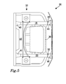
- the crash boxes 28, 30 and the lower load-path crash boxes 44, 46 are compressed simultaneously. See Figure 5 .
- the lower load-path crash boxes 44, 46 are hidden by the crash boxes 28, 30, since they are straight below.
- the crash boxes 28, 30 have a lower axial strength than the side members 18, 20.
- the crash boxes 28, 30 are thus fully or substantially fully compressed before the side members 18, 20 start to deform.
- the lower load-path crash boxes 44, 46 have a lower axial strength than the subframe 42.
- the lower load-path crash boxes 44, 46 are thus also fully or substantially fully compressed before the subframe 42 starts to deform.
- the lower load-path crash boxes 44, 46 have the same extension as the crash boxes 28, 30 in the longitudinal direction L, such that they are fully or substantially fully compressed at the same moment in time, in this case at about 23 ms, as counted from the beginning of the collision, or 315 mm stopping distance, also as counted from the beginning of the collision. See the curves of Figures 3a and 3b .
- the side members 18, 20 When the crash boxes 28, 30 are compressed, the side members 18, 20 start to deform. See Figure 6 illustrating an early part of the third phase. The deceleration is less during the third phase than during the second phase.
- the side members 18, 20 are arranged, shaped and/or dimensioned to bend substantially laterally.
- the supports 40, 41 of the side members 18, 20 are used to assist obtaining the preferred bending.
- the side members 18, 20 may be provided with predetermined bend zones 68, 70, 72 which are arranged to promote the desired substantially lateral bending. It has been found to be beneficial to use an odd number of bend zones, and in particular three bend zones 68, 70, 72 as in the illustrated embodiment.
- the side member 18, 20 will bend like a V, thereby helping to displace the relatively stiff spring tower 56, 58, which is more rigid and hence less deformable than the side member 18, 20, laterally outwards in relation to the longitudinal centre-line of the vehicle.
- the support 40, 41 Due to its shape, material and/or material thickness, the support 40, 41 is stiffer than the rest of the side member 18, 20 and thus deforms to a much lesser extent.
- the support 40, 41 helps to make the side members 18, 20 bend mainly laterally and not to the same degree, or not at all, in a vertical direction z.
- the subframe 42 starts to bend substantially in the vertical direction z, preferably substantially downwards.
- the vehicle may be provided with a steering gear, which in that case preferably is attached to the subframe 42 in such a way that that the subframe 42 pulls the steering gear downwards during bending of the subframe 42.
- the engine mount 48, 50 will start to rupture and/or attachment of the spring towers 56, 58 to the side member 18, 20 will start to detach.
- the attachment means 57, 59 attaching the spring towers 56, 58 to the side members 18, 20 are preferably arranged to detach in a progressive way, such that the spring tower 56, 58 starts to detach at a rear end of the attachment means 57, 59 and the detachment then gradually proceeds along the attachment means 57, 59 in a forward direction. Thereby, the side members 18, 20 are free to bend further, which will rupture the engine mount 48, 50 more and/or detach the spring towers 56, 58 further. Thereby, the side members 18, 20 are free to bend further and so on.
- the force needed to progressively detach the spring tower 56, 58 from the side member 18, 20 may be determined by e.g. selecting the number and distribution of the discrete attachment members, e.g. the rivets, per area unit and/or by varying the strength of the discrete attachment members. First, the rearmost rivet breaks, then the second rearmost rivet and so on. The detachment is in this case step-wise, with each step corresponding to breaking a rivet. The detachment may further be controlled by the location of the predetermined bend zones 68, 70, 72 in relation to the attachment means 57, 59.
- the discrete attachment members may be appropriate to locate the discrete attachment members, such that the predetermined bend zones 68, 70, 72 are free from discrete attachment members since otherwise a discrete attachment member could locally influence the bending properties. Purely as an example, it would be difficult to bend the side member 18, 20 along a vertical line going through a rivet.
- the rupture of the engine mount 48, 50, the detachment of the attachment of the spring towers 56, 58, the bending of the side members 18, 20 and/or the bending of the subframe 42 starts at the same time, or at least substantially the same time, i.e. within a few milliseconds of each other.
- the spring towers 56, 58 may be connected by a rally bar 64, 66 extending from one spring tower 56 to the other 58. In that case, the rally bar 64, 66 is released from the spring towers 56 and 58, as they are displaced laterally outwards during the third phase.
- cross member it is preferred that it is released from its attachment during the early part of the third phase, when the side members 18, 20 bend, such that the side members 18, 20 thereafter are free to bend.
- one or both of the lower left tie bar 52 and the lower right tie bar 54 may be adapted to rupture during the third phase, preferably during the early part, and e.g. when the rally bar 64,66 releases. Thereafter, the engine 36 is free to move.
- the subframe 42 may be arranged to be detachable from the side members 18, 20, e.g. by means of a pyrotechnic detachment device. In that case, the subframe 42 may still be attached to the side members 18, 20 during the third phase, or at least during a part of the third phase of the collision.
- Figure 7 illustrates a later part of the third phase of the collision.
- the side members 18, 20 are bent further laterally to a V-shape. Thereby, the attachment of the spring towers 56 and 58 to the side members 18, 20 are broken and the spring towers 56 and 58 have been displaced laterally outwards and rearwards in the vehicle, at least partly being pushed by the bending side member 18, 20.
- the third phase continues in the illustrated example until about 47 ms, as counted from the beginning of the collision, or 560 mm stopping distance, also as counted from the beginning of the collision. See the curves of Figures 3a and 3b .
- the stiff components of the engine compartment such as the engine 36, stack up with the body back-up structure 38. See Figure 8 .
- the fourth phase continues in the illustrated example until about 68 ms, as counted from the beginning of the collision, or 630 mm stopping distance. See the curves of Figures 3a and 3b .
- the desired course of events during the collision is obtained by arranging, dimensioning and/or shaping the above-mentioned components in relation to each other.
- the components may be located geometrically behind or beside each other.
- the components may be made of materials having different strength properties or material thickness.
- the components may have a certain shape, such as the support at the rear end of the side member. Hence, it may be achieved that the components deform in the desired order, as described above for the first to fourth phases.
Landscapes
- Engineering & Computer Science (AREA)
- Mechanical Engineering (AREA)
- Chemical & Material Sciences (AREA)
- Combustion & Propulsion (AREA)
- Transportation (AREA)
- Body Structure For Vehicles (AREA)
Priority Applications (4)
| Application Number | Priority Date | Filing Date | Title |
|---|---|---|---|
| EP19197453.4A EP3620354B1 (fr) | 2013-12-18 | 2013-12-18 | Structure frontale d'un véhicule |
| EP13197917.1A EP2886425B1 (fr) | 2013-12-18 | 2013-12-18 | Structure frontale d'un véhicule |
| CN201410756700.3A CN104724175B (zh) | 2013-12-18 | 2014-12-10 | 车辆的前部结构 |
| US14/566,765 US9428129B2 (en) | 2013-12-18 | 2014-12-11 | Front structure of a vehicle |
Applications Claiming Priority (1)
| Application Number | Priority Date | Filing Date | Title |
|---|---|---|---|
| EP13197917.1A EP2886425B1 (fr) | 2013-12-18 | 2013-12-18 | Structure frontale d'un véhicule |
Related Child Applications (1)
| Application Number | Title | Priority Date | Filing Date |
|---|---|---|---|
| EP19197453.4A Division EP3620354B1 (fr) | 2013-12-18 | 2013-12-18 | Structure frontale d'un véhicule |
Publications (2)
| Publication Number | Publication Date |
|---|---|
| EP2886425A1 true EP2886425A1 (fr) | 2015-06-24 |
| EP2886425B1 EP2886425B1 (fr) | 2019-09-25 |
Family
ID=49884961
Family Applications (2)
| Application Number | Title | Priority Date | Filing Date |
|---|---|---|---|
| EP13197917.1A Active EP2886425B1 (fr) | 2013-12-18 | 2013-12-18 | Structure frontale d'un véhicule |
| EP19197453.4A Active EP3620354B1 (fr) | 2013-12-18 | 2013-12-18 | Structure frontale d'un véhicule |
Family Applications After (1)
| Application Number | Title | Priority Date | Filing Date |
|---|---|---|---|
| EP19197453.4A Active EP3620354B1 (fr) | 2013-12-18 | 2013-12-18 | Structure frontale d'un véhicule |
Country Status (3)
| Country | Link |
|---|---|
| US (1) | US9428129B2 (fr) |
| EP (2) | EP2886425B1 (fr) |
| CN (1) | CN104724175B (fr) |
Families Citing this family (16)
| Publication number | Priority date | Publication date | Assignee | Title |
|---|---|---|---|---|
| JP2015168364A (ja) * | 2014-03-07 | 2015-09-28 | トヨタ自動車株式会社 | 車体の前部構造体 |
| KR101703596B1 (ko) * | 2015-07-24 | 2017-02-07 | 현대자동차 주식회사 | 전방 차체 구조 |
| WO2017098293A1 (fr) * | 2015-12-09 | 2017-06-15 | Arcelormittal | Structure de carrosserie avant de véhicule et son procédé de fabrication |
| EP3300956B1 (fr) | 2016-09-30 | 2020-01-01 | Ningbo Geely Automobile Research & Development Co., Ltd. | Système de gestion des plantages |
| FR3063709B1 (fr) * | 2017-03-07 | 2019-06-07 | Renault S.A.S | Structure de caisse de vehicule automobile. |
| JP6923876B2 (ja) * | 2017-03-28 | 2021-08-25 | 株式会社ワイテック | 自動車の前部車体構造 |
| US10494028B2 (en) | 2017-06-21 | 2019-12-03 | Ford Global Technologies, Llc | Vehicle frame structure |
| US11021126B1 (en) * | 2017-06-30 | 2021-06-01 | Apple Inc. | Windshield area intrusion control |
| DE102017007309B4 (de) * | 2017-08-02 | 2019-07-11 | Audi Ag | Stoßfängeranordnung mit einem Querträger und zwei Crashboxen |
| EP3444138A1 (fr) * | 2017-08-17 | 2019-02-20 | Volvo Car Corporation | Véhicule |
| EP3480036A1 (fr) * | 2017-11-07 | 2019-05-08 | Volvo Car Corporation | Système de suspension de roues d'un véhicule |
| EP3971065B1 (fr) * | 2018-05-15 | 2023-12-06 | Volvo Car Corporation | Véhicule électrique |
| US10822039B2 (en) * | 2019-02-18 | 2020-11-03 | GM Global Technology Operations LLC | Body rocker, battery cross-bar, and body cross-bar configuration for load distribution between vehicle body and under-vehicle battery |
| FR3122147B1 (fr) * | 2021-04-22 | 2023-03-10 | Psa Automobiles Sa | Vehicule automobile equipe d’un dispositif d’impact entre la motorisation et le berceau avant |
| US11623692B2 (en) | 2021-07-09 | 2023-04-11 | Volvo Car Corporation | Deformable rear crossmembers with special extrusion section design for bending down in crash loadcases |
| EP4253104A1 (fr) | 2022-04-01 | 2023-10-04 | Hopper Mobility GmbH | Dispositif de suspension de roue |
Citations (11)
| Publication number | Priority date | Publication date | Assignee | Title |
|---|---|---|---|---|
| JPH0391282U (fr) * | 1989-12-28 | 1991-09-18 | ||
| JP2000016327A (ja) | 1998-07-01 | 2000-01-18 | Toyota Motor Corp | 自動車の車体の前部構造 |
| US6113178A (en) * | 1998-08-31 | 2000-09-05 | Trw Vehicle Safety Systems Inc. | Vehicle energy absorption apparatus |
| JP2002002528A (ja) * | 2000-06-15 | 2002-01-09 | Mitsubishi Motors Corp | 車体構造 |
| US6705670B2 (en) | 2000-06-13 | 2004-03-16 | Volvo Car Corporation | Axially loaded arrangement for a motor vehicle frame |
| JP2004148960A (ja) * | 2002-10-30 | 2004-05-27 | Mazda Motor Corp | サスペンションクロスメンバの取付構造 |
| JP2007216901A (ja) * | 2006-02-20 | 2007-08-30 | Toyota Motor Corp | 車体前部構造 |
| JP2008222185A (ja) * | 2007-03-16 | 2008-09-25 | Mazda Motor Corp | 車体前部構造 |
| US20110198832A1 (en) * | 2010-02-15 | 2011-08-18 | Mazda Motor Corporation | Lower structure of automotive vehicle |
| US20110316295A1 (en) * | 2010-06-28 | 2011-12-29 | Mazda Motor Corporation | Lower vehicle-body structure of vehicle |
| EP2423078A1 (fr) * | 2010-08-25 | 2012-02-29 | Nissan Motor Co., Ltd. | Carrosserie de véhicule |
Family Cites Families (12)
| Publication number | Priority date | Publication date | Assignee | Title |
|---|---|---|---|---|
| JP2005324654A (ja) * | 2004-05-13 | 2005-11-24 | Nissan Motor Co Ltd | 車体前部構造 |
| JP4779471B2 (ja) * | 2004-10-27 | 2011-09-28 | 日産自動車株式会社 | 車両の前部構造 |
| JP5077541B2 (ja) * | 2007-08-29 | 2012-11-21 | スズキ株式会社 | 車体前部構造 |
| US7635157B2 (en) * | 2007-09-11 | 2009-12-22 | GM Global Technology Operation, INC | Vehicle hood assembly with rippled cushion support |
| MY155636A (en) * | 2007-12-04 | 2015-11-13 | Honda Motor Co Ltd | Vehicle front body structure |
| JP5357953B2 (ja) * | 2011-04-01 | 2013-12-04 | 本田技研工業株式会社 | 車体前部構造 |
| KR101210024B1 (ko) * | 2011-06-08 | 2012-12-07 | 현대자동차주식회사 | 차체의 전방 연결구조 |
| CN102390434B (zh) * | 2011-10-19 | 2013-08-21 | 湖南大学 | 汽车前纵梁结构 |
| CN103796905A (zh) * | 2011-10-25 | 2014-05-14 | 丰田自动车株式会社 | 骨架构件 |
| US8967701B2 (en) * | 2013-03-01 | 2015-03-03 | Ford Global Technologies, Llc | Integrated shotgun rail deflector |
| ITTO20130474A1 (it) * | 2013-06-07 | 2014-12-08 | Fiat Group Automobiles Spa | Autoveicolo provvisto di un sistema di sgancio per staccare una traversa nel vano motore in caso d'urto frontale |
| EP2886423B1 (fr) * | 2013-12-18 | 2017-05-17 | Volvo Car Corporation | Agencement de structure avant d'un véhicule |
-
2013
- 2013-12-18 EP EP13197917.1A patent/EP2886425B1/fr active Active
- 2013-12-18 EP EP19197453.4A patent/EP3620354B1/fr active Active
-
2014
- 2014-12-10 CN CN201410756700.3A patent/CN104724175B/zh active Active
- 2014-12-11 US US14/566,765 patent/US9428129B2/en active Active
Patent Citations (11)
| Publication number | Priority date | Publication date | Assignee | Title |
|---|---|---|---|---|
| JPH0391282U (fr) * | 1989-12-28 | 1991-09-18 | ||
| JP2000016327A (ja) | 1998-07-01 | 2000-01-18 | Toyota Motor Corp | 自動車の車体の前部構造 |
| US6113178A (en) * | 1998-08-31 | 2000-09-05 | Trw Vehicle Safety Systems Inc. | Vehicle energy absorption apparatus |
| US6705670B2 (en) | 2000-06-13 | 2004-03-16 | Volvo Car Corporation | Axially loaded arrangement for a motor vehicle frame |
| JP2002002528A (ja) * | 2000-06-15 | 2002-01-09 | Mitsubishi Motors Corp | 車体構造 |
| JP2004148960A (ja) * | 2002-10-30 | 2004-05-27 | Mazda Motor Corp | サスペンションクロスメンバの取付構造 |
| JP2007216901A (ja) * | 2006-02-20 | 2007-08-30 | Toyota Motor Corp | 車体前部構造 |
| JP2008222185A (ja) * | 2007-03-16 | 2008-09-25 | Mazda Motor Corp | 車体前部構造 |
| US20110198832A1 (en) * | 2010-02-15 | 2011-08-18 | Mazda Motor Corporation | Lower structure of automotive vehicle |
| US20110316295A1 (en) * | 2010-06-28 | 2011-12-29 | Mazda Motor Corporation | Lower vehicle-body structure of vehicle |
| EP2423078A1 (fr) * | 2010-08-25 | 2012-02-29 | Nissan Motor Co., Ltd. | Carrosserie de véhicule |
Also Published As
| Publication number | Publication date |
|---|---|
| US20150165994A1 (en) | 2015-06-18 |
| EP2886425B1 (fr) | 2019-09-25 |
| CN104724175B (zh) | 2018-08-14 |
| EP3620354B1 (fr) | 2021-06-02 |
| US9428129B2 (en) | 2016-08-30 |
| CN104724175A (zh) | 2015-06-24 |
| EP3620354A1 (fr) | 2020-03-11 |
Similar Documents
| Publication | Publication Date | Title |
|---|---|---|
| EP3620354B1 (fr) | Structure frontale d'un véhicule | |
| EP2886423B1 (fr) | Agencement de structure avant d'un véhicule | |
| CN105980242B (zh) | 车身前部构造 | |
| EP2476603B1 (fr) | Composants pour structure de collisions de véhicules à moteur | |
| CN104781133B (zh) | 针对轻微重叠的碰撞设计的机动车车身 | |
| EP2105372B1 (fr) | Structure de cadre pour véhicule automobile, véhicule automobile fourni avec celle-ci et procédé pour fournir une structure de cadre | |
| US7913790B2 (en) | Structure of instrument panel area of vehicle | |
| CN100434325C (zh) | 用于提高碰撞中安全性的底盘辅助车架设备 | |
| CN105905057B (zh) | 车辆用保险杠增强构造 | |
| EP3611080B1 (fr) | Structure inférieure d'un véhicule | |
| CN107531203A (zh) | 绞盘安装装置 | |
| JP5945762B2 (ja) | 車両前部構造 | |
| US9365240B2 (en) | Frontal collision impact absorbing device for vehicle | |
| JP5417463B2 (ja) | 自動車の車体前部構造 | |
| US7798526B2 (en) | Steering column assembly | |
| CN109094654A (zh) | 车辆车架结构 | |
| CN103608240A (zh) | 冲击吸收式转向装置 | |
| EP1857331B1 (fr) | Dispositif de sécurité | |
| US8926002B2 (en) | Motor vehicle body | |
| EP3194250B1 (fr) | Camion à cabine avancée | |
| CN113039096A (zh) | 汽车用吸能结构单元及其吸能件和加强件 | |
| CN107635859B (zh) | 用于保留副车架的后区段的副车架方法和结构 | |
| JP2013151255A (ja) | 車両の後部構造 | |
| CN104210553A (zh) | 车辆前部部分结构 | |
| WO2008120232A2 (fr) | Structure de support de colonne de direction améliorée |
Legal Events
| Date | Code | Title | Description |
|---|---|---|---|
| PUAI | Public reference made under article 153(3) epc to a published international application that has entered the european phase |
Free format text: ORIGINAL CODE: 0009012 |
|
| 17P | Request for examination filed |
Effective date: 20131218 |
|
| AK | Designated contracting states |
Kind code of ref document: A1 Designated state(s): AL AT BE BG CH CY CZ DE DK EE ES FI FR GB GR HR HU IE IS IT LI LT LU LV MC MK MT NL NO PL PT RO RS SE SI SK SM TR |
|
| AX | Request for extension of the european patent |
Extension state: BA ME |
|
| R17P | Request for examination filed (corrected) |
Effective date: 20160104 |
|
| RBV | Designated contracting states (corrected) |
Designated state(s): AL AT BE BG CH CY CZ DE DK EE ES FI FR GB GR HR HU IE IS IT LI LT LU LV MC MK MT NL NO PL PT RO RS SE SI SK SM TR |
|
| STAA | Information on the status of an ep patent application or granted ep patent |
Free format text: STATUS: EXAMINATION IS IN PROGRESS |
|
| 17Q | First examination report despatched |
Effective date: 20171201 |
|
| GRAP | Despatch of communication of intention to grant a patent |
Free format text: ORIGINAL CODE: EPIDOSNIGR1 |
|
| STAA | Information on the status of an ep patent application or granted ep patent |
Free format text: STATUS: GRANT OF PATENT IS INTENDED |
|
| INTG | Intention to grant announced |
Effective date: 20190417 |
|
| GRAS | Grant fee paid |
Free format text: ORIGINAL CODE: EPIDOSNIGR3 |
|
| GRAA | (expected) grant |
Free format text: ORIGINAL CODE: 0009210 |
|
| STAA | Information on the status of an ep patent application or granted ep patent |
Free format text: STATUS: THE PATENT HAS BEEN GRANTED |
|
| AK | Designated contracting states |
Kind code of ref document: B1 Designated state(s): AL AT BE BG CH CY CZ DE DK EE ES FI FR GB GR HR HU IE IS IT LI LT LU LV MC MK MT NL NO PL PT RO RS SE SI SK SM TR |
|
| REG | Reference to a national code |
Ref country code: GB Ref legal event code: FG4D |
|
| REG | Reference to a national code |
Ref country code: CH Ref legal event code: EP |
|
| REG | Reference to a national code |
Ref country code: DE Ref legal event code: R096 Ref document number: 602013060912 Country of ref document: DE |
|
| REG | Reference to a national code |
Ref country code: AT Ref legal event code: REF Ref document number: 1183562 Country of ref document: AT Kind code of ref document: T Effective date: 20191015 |
|
| REG | Reference to a national code |
Ref country code: IE Ref legal event code: FG4D |
|
| REG | Reference to a national code |
Ref country code: NL Ref legal event code: MP Effective date: 20190925 |
|
| PG25 | Lapsed in a contracting state [announced via postgrant information from national office to epo] |
Ref country code: FI Free format text: LAPSE BECAUSE OF FAILURE TO SUBMIT A TRANSLATION OF THE DESCRIPTION OR TO PAY THE FEE WITHIN THE PRESCRIBED TIME-LIMIT Effective date: 20190925 Ref country code: LT Free format text: LAPSE BECAUSE OF FAILURE TO SUBMIT A TRANSLATION OF THE DESCRIPTION OR TO PAY THE FEE WITHIN THE PRESCRIBED TIME-LIMIT Effective date: 20190925 Ref country code: SE Free format text: LAPSE BECAUSE OF FAILURE TO SUBMIT A TRANSLATION OF THE DESCRIPTION OR TO PAY THE FEE WITHIN THE PRESCRIBED TIME-LIMIT Effective date: 20190925 Ref country code: HR Free format text: LAPSE BECAUSE OF FAILURE TO SUBMIT A TRANSLATION OF THE DESCRIPTION OR TO PAY THE FEE WITHIN THE PRESCRIBED TIME-LIMIT Effective date: 20190925 Ref country code: BG Free format text: LAPSE BECAUSE OF FAILURE TO SUBMIT A TRANSLATION OF THE DESCRIPTION OR TO PAY THE FEE WITHIN THE PRESCRIBED TIME-LIMIT Effective date: 20191225 Ref country code: NO Free format text: LAPSE BECAUSE OF FAILURE TO SUBMIT A TRANSLATION OF THE DESCRIPTION OR TO PAY THE FEE WITHIN THE PRESCRIBED TIME-LIMIT Effective date: 20191225 |
|
| REG | Reference to a national code |
Ref country code: LT Ref legal event code: MG4D |
|
| PG25 | Lapsed in a contracting state [announced via postgrant information from national office to epo] |
Ref country code: LV Free format text: LAPSE BECAUSE OF FAILURE TO SUBMIT A TRANSLATION OF THE DESCRIPTION OR TO PAY THE FEE WITHIN THE PRESCRIBED TIME-LIMIT Effective date: 20190925 Ref country code: RS Free format text: LAPSE BECAUSE OF FAILURE TO SUBMIT A TRANSLATION OF THE DESCRIPTION OR TO PAY THE FEE WITHIN THE PRESCRIBED TIME-LIMIT Effective date: 20190925 Ref country code: GR Free format text: LAPSE BECAUSE OF FAILURE TO SUBMIT A TRANSLATION OF THE DESCRIPTION OR TO PAY THE FEE WITHIN THE PRESCRIBED TIME-LIMIT Effective date: 20191226 |
|
| REG | Reference to a national code |
Ref country code: AT Ref legal event code: MK05 Ref document number: 1183562 Country of ref document: AT Kind code of ref document: T Effective date: 20190925 |
|
| PG25 | Lapsed in a contracting state [announced via postgrant information from national office to epo] |
Ref country code: AT Free format text: LAPSE BECAUSE OF FAILURE TO SUBMIT A TRANSLATION OF THE DESCRIPTION OR TO PAY THE FEE WITHIN THE PRESCRIBED TIME-LIMIT Effective date: 20190925 Ref country code: PL Free format text: LAPSE BECAUSE OF FAILURE TO SUBMIT A TRANSLATION OF THE DESCRIPTION OR TO PAY THE FEE WITHIN THE PRESCRIBED TIME-LIMIT Effective date: 20190925 Ref country code: EE Free format text: LAPSE BECAUSE OF FAILURE TO SUBMIT A TRANSLATION OF THE DESCRIPTION OR TO PAY THE FEE WITHIN THE PRESCRIBED TIME-LIMIT Effective date: 20190925 Ref country code: ES Free format text: LAPSE BECAUSE OF FAILURE TO SUBMIT A TRANSLATION OF THE DESCRIPTION OR TO PAY THE FEE WITHIN THE PRESCRIBED TIME-LIMIT Effective date: 20190925 Ref country code: RO Free format text: LAPSE BECAUSE OF FAILURE TO SUBMIT A TRANSLATION OF THE DESCRIPTION OR TO PAY THE FEE WITHIN THE PRESCRIBED TIME-LIMIT Effective date: 20190925 Ref country code: NL Free format text: LAPSE BECAUSE OF FAILURE TO SUBMIT A TRANSLATION OF THE DESCRIPTION OR TO PAY THE FEE WITHIN THE PRESCRIBED TIME-LIMIT Effective date: 20190925 Ref country code: PT Free format text: LAPSE BECAUSE OF FAILURE TO SUBMIT A TRANSLATION OF THE DESCRIPTION OR TO PAY THE FEE WITHIN THE PRESCRIBED TIME-LIMIT Effective date: 20200127 Ref country code: AL Free format text: LAPSE BECAUSE OF FAILURE TO SUBMIT A TRANSLATION OF THE DESCRIPTION OR TO PAY THE FEE WITHIN THE PRESCRIBED TIME-LIMIT Effective date: 20190925 |
|
| PG25 | Lapsed in a contracting state [announced via postgrant information from national office to epo] |
Ref country code: SM Free format text: LAPSE BECAUSE OF FAILURE TO SUBMIT A TRANSLATION OF THE DESCRIPTION OR TO PAY THE FEE WITHIN THE PRESCRIBED TIME-LIMIT Effective date: 20190925 Ref country code: SK Free format text: LAPSE BECAUSE OF FAILURE TO SUBMIT A TRANSLATION OF THE DESCRIPTION OR TO PAY THE FEE WITHIN THE PRESCRIBED TIME-LIMIT Effective date: 20190925 Ref country code: IS Free format text: LAPSE BECAUSE OF FAILURE TO SUBMIT A TRANSLATION OF THE DESCRIPTION OR TO PAY THE FEE WITHIN THE PRESCRIBED TIME-LIMIT Effective date: 20200224 Ref country code: CZ Free format text: LAPSE BECAUSE OF FAILURE TO SUBMIT A TRANSLATION OF THE DESCRIPTION OR TO PAY THE FEE WITHIN THE PRESCRIBED TIME-LIMIT Effective date: 20190925 |
|
| REG | Reference to a national code |
Ref country code: DE Ref legal event code: R097 Ref document number: 602013060912 Country of ref document: DE |
|
| PG2D | Information on lapse in contracting state deleted |
Ref country code: IS |
|
| PG25 | Lapsed in a contracting state [announced via postgrant information from national office to epo] |
Ref country code: DK Free format text: LAPSE BECAUSE OF FAILURE TO SUBMIT A TRANSLATION OF THE DESCRIPTION OR TO PAY THE FEE WITHIN THE PRESCRIBED TIME-LIMIT Effective date: 20190925 Ref country code: IS Free format text: LAPSE BECAUSE OF FAILURE TO SUBMIT A TRANSLATION OF THE DESCRIPTION OR TO PAY THE FEE WITHIN THE PRESCRIBED TIME-LIMIT Effective date: 20200126 |
|
| PLBE | No opposition filed within time limit |
Free format text: ORIGINAL CODE: 0009261 |
|
| REG | Reference to a national code |
Ref country code: CH Ref legal event code: PL |
|
| STAA | Information on the status of an ep patent application or granted ep patent |
Free format text: STATUS: NO OPPOSITION FILED WITHIN TIME LIMIT |
|
| REG | Reference to a national code |
Ref country code: BE Ref legal event code: MM Effective date: 20191231 |
|
| PG25 | Lapsed in a contracting state [announced via postgrant information from national office to epo] |
Ref country code: MC Free format text: LAPSE BECAUSE OF FAILURE TO SUBMIT A TRANSLATION OF THE DESCRIPTION OR TO PAY THE FEE WITHIN THE PRESCRIBED TIME-LIMIT Effective date: 20190925 |
|
| 26N | No opposition filed |
Effective date: 20200626 |
|
| GBPC | Gb: european patent ceased through non-payment of renewal fee |
Effective date: 20191225 |
|
| PG25 | Lapsed in a contracting state [announced via postgrant information from national office to epo] |
Ref country code: IE Free format text: LAPSE BECAUSE OF NON-PAYMENT OF DUE FEES Effective date: 20191218 Ref country code: LU Free format text: LAPSE BECAUSE OF NON-PAYMENT OF DUE FEES Effective date: 20191218 Ref country code: GB Free format text: LAPSE BECAUSE OF NON-PAYMENT OF DUE FEES Effective date: 20191225 |
|
| PG25 | Lapsed in a contracting state [announced via postgrant information from national office to epo] |
Ref country code: LI Free format text: LAPSE BECAUSE OF NON-PAYMENT OF DUE FEES Effective date: 20191231 Ref country code: SI Free format text: LAPSE BECAUSE OF FAILURE TO SUBMIT A TRANSLATION OF THE DESCRIPTION OR TO PAY THE FEE WITHIN THE PRESCRIBED TIME-LIMIT Effective date: 20190925 Ref country code: BE Free format text: LAPSE BECAUSE OF NON-PAYMENT OF DUE FEES Effective date: 20191231 Ref country code: CH Free format text: LAPSE BECAUSE OF NON-PAYMENT OF DUE FEES Effective date: 20191231 |
|
| PG25 | Lapsed in a contracting state [announced via postgrant information from national office to epo] |
Ref country code: CY Free format text: LAPSE BECAUSE OF FAILURE TO SUBMIT A TRANSLATION OF THE DESCRIPTION OR TO PAY THE FEE WITHIN THE PRESCRIBED TIME-LIMIT Effective date: 20190925 |
|
| PG25 | Lapsed in a contracting state [announced via postgrant information from national office to epo] |
Ref country code: HU Free format text: LAPSE BECAUSE OF FAILURE TO SUBMIT A TRANSLATION OF THE DESCRIPTION OR TO PAY THE FEE WITHIN THE PRESCRIBED TIME-LIMIT; INVALID AB INITIO Effective date: 20131218 Ref country code: MT Free format text: LAPSE BECAUSE OF FAILURE TO SUBMIT A TRANSLATION OF THE DESCRIPTION OR TO PAY THE FEE WITHIN THE PRESCRIBED TIME-LIMIT Effective date: 20190925 |
|
| PG25 | Lapsed in a contracting state [announced via postgrant information from national office to epo] |
Ref country code: TR Free format text: LAPSE BECAUSE OF FAILURE TO SUBMIT A TRANSLATION OF THE DESCRIPTION OR TO PAY THE FEE WITHIN THE PRESCRIBED TIME-LIMIT Effective date: 20190925 |
|
| PG25 | Lapsed in a contracting state [announced via postgrant information from national office to epo] |
Ref country code: MK Free format text: LAPSE BECAUSE OF FAILURE TO SUBMIT A TRANSLATION OF THE DESCRIPTION OR TO PAY THE FEE WITHIN THE PRESCRIBED TIME-LIMIT Effective date: 20190925 |
|
| PGFP | Annual fee paid to national office [announced via postgrant information from national office to epo] |
Ref country code: IT Payment date: 20221122 Year of fee payment: 10 |
|
| P01 | Opt-out of the competence of the unified patent court (upc) registered |
Effective date: 20231212 |
|
| PGFP | Annual fee paid to national office [announced via postgrant information from national office to epo] |
Ref country code: FR Payment date: 20231122 Year of fee payment: 11 Ref country code: DE Payment date: 20231121 Year of fee payment: 11 |