EP2884028A2 - Fahrzeugschlüsselvorrichtung - Google Patents
Fahrzeugschlüsselvorrichtung Download PDFInfo
- Publication number
- EP2884028A2 EP2884028A2 EP14195406.5A EP14195406A EP2884028A2 EP 2884028 A2 EP2884028 A2 EP 2884028A2 EP 14195406 A EP14195406 A EP 14195406A EP 2884028 A2 EP2884028 A2 EP 2884028A2
- Authority
- EP
- European Patent Office
- Prior art keywords
- key
- blade
- insertion slot
- cover
- blade insertion
- Prior art date
- Legal status (The legal status is an assumption and is not a legal conclusion. Google has not performed a legal analysis and makes no representation as to the accuracy of the status listed.)
- Granted
Links
- 238000003780 insertion Methods 0.000 claims abstract description 120
- 230000037431 insertion Effects 0.000 claims abstract description 120
- 238000000034 method Methods 0.000 description 14
- 230000005489 elastic deformation Effects 0.000 description 6
- 229920003002 synthetic resin Polymers 0.000 description 6
- 239000000057 synthetic resin Substances 0.000 description 6
- 238000004891 communication Methods 0.000 description 5
- 239000002184 metal Substances 0.000 description 4
- 230000000694 effects Effects 0.000 description 2
- 239000000463 material Substances 0.000 description 2
- 230000000717 retained effect Effects 0.000 description 2
- 238000005516 engineering process Methods 0.000 description 1
- 238000001746 injection moulding Methods 0.000 description 1
- 230000002093 peripheral effect Effects 0.000 description 1
- 238000003825 pressing Methods 0.000 description 1
Images




Classifications
-
- E—FIXED CONSTRUCTIONS
- E05—LOCKS; KEYS; WINDOW OR DOOR FITTINGS; SAFES
- E05B—LOCKS; ACCESSORIES THEREFOR; HANDCUFFS
- E05B19/00—Keys; Accessories therefor
- E05B19/04—Construction of the bow or head of the key; Attaching the bow to the shank
-
- G—PHYSICS
- G07—CHECKING-DEVICES
- G07C—TIME OR ATTENDANCE REGISTERS; REGISTERING OR INDICATING THE WORKING OF MACHINES; GENERATING RANDOM NUMBERS; VOTING OR LOTTERY APPARATUS; ARRANGEMENTS, SYSTEMS OR APPARATUS FOR CHECKING NOT PROVIDED FOR ELSEWHERE
- G07C9/00—Individual registration on entry or exit
- G07C9/00174—Electronically operated locks; Circuits therefor; Nonmechanical keys therefor, e.g. passive or active electrical keys or other data carriers without mechanical keys
- G07C9/00944—Details of construction or manufacture
-
- G—PHYSICS
- G07—CHECKING-DEVICES
- G07C—TIME OR ATTENDANCE REGISTERS; REGISTERING OR INDICATING THE WORKING OF MACHINES; GENERATING RANDOM NUMBERS; VOTING OR LOTTERY APPARATUS; ARRANGEMENTS, SYSTEMS OR APPARATUS FOR CHECKING NOT PROVIDED FOR ELSEWHERE
- G07C9/00—Individual registration on entry or exit
- G07C9/00174—Electronically operated locks; Circuits therefor; Nonmechanical keys therefor, e.g. passive or active electrical keys or other data carriers without mechanical keys
- G07C9/00944—Details of construction or manufacture
- G07C2009/00952—Electronic keys comprising a mechanical key within their housing, e.g. extractable or retractable emergency key
-
- G—PHYSICS
- G07—CHECKING-DEVICES
- G07C—TIME OR ATTENDANCE REGISTERS; REGISTERING OR INDICATING THE WORKING OF MACHINES; GENERATING RANDOM NUMBERS; VOTING OR LOTTERY APPARATUS; ARRANGEMENTS, SYSTEMS OR APPARATUS FOR CHECKING NOT PROVIDED FOR ELSEWHERE
- G07C9/00—Individual registration on entry or exit
- G07C9/00174—Electronically operated locks; Circuits therefor; Nonmechanical keys therefor, e.g. passive or active electrical keys or other data carriers without mechanical keys
- G07C2009/00968—Electronically operated locks; Circuits therefor; Nonmechanical keys therefor, e.g. passive or active electrical keys or other data carriers without mechanical keys shape of the data carrier
- G07C2009/00984—Electronically operated locks; Circuits therefor; Nonmechanical keys therefor, e.g. passive or active electrical keys or other data carriers without mechanical keys shape of the data carrier fob
-
- G—PHYSICS
- G07—CHECKING-DEVICES
- G07C—TIME OR ATTENDANCE REGISTERS; REGISTERING OR INDICATING THE WORKING OF MACHINES; GENERATING RANDOM NUMBERS; VOTING OR LOTTERY APPARATUS; ARRANGEMENTS, SYSTEMS OR APPARATUS FOR CHECKING NOT PROVIDED FOR ELSEWHERE
- G07C9/00—Individual registration on entry or exit
- G07C9/00174—Electronically operated locks; Circuits therefor; Nonmechanical keys therefor, e.g. passive or active electrical keys or other data carriers without mechanical keys
- G07C2009/00968—Electronically operated locks; Circuits therefor; Nonmechanical keys therefor, e.g. passive or active electrical keys or other data carriers without mechanical keys shape of the data carrier
- G07C2009/00992—Electronically operated locks; Circuits therefor; Nonmechanical keys therefor, e.g. passive or active electrical keys or other data carriers without mechanical keys shape of the data carrier mechanical key
Definitions
- the present invention relates to a vehicle key device and in particular to a vehicle key device that includes a less number of components and that is easy to assemble.
- a vehicle key device including a key head portion housing an electronic circuit for radio communication and a battery for power supply, and a key blade functioning as an emergency mechanical key has been widespread as a handheld device included in a keyless entry system or the like.
- a keyless entry system allows a user of a vehicle to perform vehicle operations, such as locking or unlocking of the doors of the vehicle, without using a mechanical key but over the radio communication between an onboard device provided in the vehicle and a handheld device carried by the user.
- Figs. 12A to 12C illustrate a configuration of an unlocking key 200 according to Japanese Unexamined Patent Application Publication No. 2007-297775 .
- Fig. 12A is a plan view of the unlocking key 200.
- Fig. 12B is a sectional view taken along line XIIB-XIIB illustrated in Fig. 12A.
- Fig. 12C is another sectional view taken along line XIIC-XIIC illustrated in Fig. 12A with a screw 205 fastened.
- the unlocking key 200 includes a key head portion 202 having a blade insertion hole 201, a key blade 204 one end of which is inserted into the blade insertion hole 201 and is fastened there, and the screw 205 with which the key blade 204 is fastened to the key head portion 202.
- the key blade 204 has a rectangular sectional shape.
- the one end of the key blade 204 has an inserted head portion 204a.
- a screw hole 203 is provided in the center of the inserted head portion 204a.
- One of wide surfaces of the inserted head portion 204a has sloping surfaces 207a at the right and left edges thereof.
- the key head portion 202 includes a first cover 208 and a second cover 209 that are stacked one on top of the other.
- the key head portion 202 houses an electronic circuit, a battery, and so forth (all not illustrated).
- the first cover 208 and the second cover 209 are separably connected to each other.
- the blade insertion hole 201 is provide in a sidewall 210 of the first cover 208 and has a rectangular sectional shape whose long side is slightly longer than the width of the key blade 204.
- the first cover 208 has two projection insertion holes 208a and one screw insertion hole 208b in a surface thereof that adjoins the second cover 209.
- the second cover 209 has two lines of interference projections 206 on a surface thereof that adjoins the first cover 208.
- the interference projections 206 each have a sectional shape that is insertable into a corresponding ones of the projection insertion holes 208a.
- One of edges of each of the interference projections 206 that is on a side from which the key blade 204 is inserted and that faces a corresponding one of the sloping surfaces 207a is chamfered and provides a sloping surface 207b.
- the second cover 209 has a screw insertion hole 209b that communicates with the screw insertion hole 208b provided in the first cover 208.
- the screw insertion hole 209b includes, at an end thereof on the upper side in Fig. 12B , a receiving recess 209d that receives the head of the screw 205.
- the unlocking key 200 is assembled by inserting the inserted head portion 204a of the key blade 204 into the blade insertion hole 201 of the key head portion 202 and then fastening the key head portion 202 and the key blade 204 to each other with the screw 205.
- the sloping surfaces 207a of the key blade 204 and the sloping surfaces 207b of the key head portion 202 are pressed against each other, whereby the key blade 204 is prevented from wobbling.
- Such a vehicle key device is desired to include a less number of components and to be easy to assemble from viewpoints of cost reduction and so forth.
- a component such as the screw 205, for fastening the key blade 204 to the key head portion 202 is necessary, which increases the number of components.
- a screwing work or the like is necessary in the process of assembling the unlocking key 200, which makes the process of assembling the unlocking key 200 complicated.
- the present invention provides a vehicle key device including a less number of components and that is easy to assemble.
- an aspect of the present invention provides a vehicle key device including a key head portion and a key blade fastened to the key head portion.
- the key head portion includes a first cover having a blade insertion slot into which the key blade is inserted, and a second cover fitted to the first cover.
- the key blade includes an inserted portion inserted into the blade insertion slot and having a through hole.
- the blade insertion slot includes inner walls including an upper wall, a lower wall, a left wall, a right wall, and a rear wall; and an upper end portion providing the upper wall.
- the upper end portion includes an elastic part provided between a pair of notches.
- the elastic part includes a first projection that snap-engages with the through hole of the key blade when the key blade is inserted into the blade insertion slot.
- the second cover is fitted to the first cover in such a manner as to press the upper end portion of the blade insertion slot.
- the first projection provided on the elastic part of the blade insertion slot snap-engages with the through hole provided in the inserted portion of the key blade.
- the key blade is prevented from moving. Accordingly, the key blade is prevented from coming off the blade insertion slot.
- the second cover presses the upper end portion of the blade insertion slot from the upper side, the elastic part of the blade insertion slot is prevented from undergoing upward elastic deformation. Accordingly, the snap engagement between the first projection and the through hole is stabilized. Consequently, in the vehicle key device configured as described above, the key blade is fastened to the key head portion without screwing the key blade and the key head portion together. Since no screws for screwing are necessary, the number of components is reduced. Moreover, since screwing is unnecessary, the assembling method is simplified.
- the upper wall, the lower wall, the left wall, and the right wall of the blade insertion slot may each have a plurality of second projections that support the inserted portion of the key blade.
- the rear wall may have a contact surface with which the inserted portion of the key blade comes into contact.
- the upper wall, the lower wall, the left wall, and the right wall of the blade insertion slot each have the plurality of second projections. Since the tops of such projections are easily deformable, the dimensional variations in the key head portion and in the key blade are absorbed by the deformation of the tops of the second projections, whereby the tops of the second projections are in close contact with the inserted portion of the key blade. Since the tops of the second projections are closely in contact with and thus support the inserted portion of the key blade, the key blade is prevented from moving in the vertical and horizontal directions. Moreover, the rear wall of the blade insertion slot provides a contact surface that comes into contact with the inserted portion of the key blade.
- the key blade Since the contact surface of the blade insertion slot comes into contact with the inserted portion of the key blade, the key blade is prevented from moving in the direction of insertion of the key blade. Consequently, in the vehicle key device configured as described above, the key blade is prevented from wobbling in the assembling process.
- the lower wall may have a third projection that engages with the through hole of the key blade.
- the lower wall of the blade insertion slot has the third projection that engages with the through hole of the key blade. Since the first projection and the third projection of the blade insertion slot engage with the through hole of the key blade, the force of preventing the key blade from moving is increased. Consequently, the key blade is more effectively prevented from coming off the blade insertion slot than in a case where only the first projection of the blade insertion slot engages with the through hole of the key blade.
- a vehicle key device including a less number of components and that is easy to assemble is provided.
- the X1 side corresponds to the left side
- the X2 side corresponds to the right side
- the Y1 side corresponds to the front side
- the Y2 side corresponds to the rear side
- the Z1 side corresponds to the upper side
- the Z2 side corresponds to the lower side.
- FIG. 1 is a perspective view illustrating the configuration of the vehicle key device 1 according to the first embodiment of the present invention.
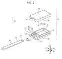
- Fig. 2 is an exploded perspective view illustrating the configuration of the vehicle key device 1 according to the first embodiment of the present invention.
- Figs. 3A and 3B illustrate a configuration of a first cover 20 illustrated in Fig. 2 .
- Fig. 3A is a top view.
- Fig. 3B is a sectional view taken along line IIIB-IIIB illustrated in Fig. 3A .
- Figs. 4A and 4B illustrate a configuration of a blade insertion slot 30 illustrated in Fig. 2 .
- Fig. 1 is a perspective view illustrating the configuration of the vehicle key device 1 according to the first embodiment of the present invention.
- Fig. 2 is an exploded perspective view illustrating the configuration of the vehicle key device 1 according to the first embodiment of the present invention.
- Figs. 3A and 3B illustrate a configuration of a first cover 20 illustrated in Fig. 2
- FIG. 4A is a sectional view taken along line IVA-IVA illustrated in Fig. 3A and illustrates a configuration around the blade insertion slot 30.
- Fig. 4B is a sectional view taken along line IVB-IVB illustrated in Fig. 3A and illustrates the configuration around the blade insertion slot 30.
- Figs. 5A and 5B illustrate a configuration of a second cover 40 illustrated in Fig. 2 .
- Fig. 5A is a bottom view.
- Fig. 5B is a sectional view taken along line VB-VB illustrated in Fig. 5A .
- Figs. 6A and 6B illustrate a configuration of a key blade 50 illustrated in Fig. 2 .
- Fig. 6A is a top view.
- Fig. 6B is a sectional view taken along line VIB-VIB illustrated in Fig. 6A .
- the vehicle key device 1 is used as a handheld device included in a keyless entry system.
- the keyless entry system allows a user of a vehicle to perform vehicle operations, such as locking or unlocking of the doors of the vehicle, without using a mechanical key but over the radio communication between an onboard device provided in the vehicle and a handheld device carried by the user.
- the vehicle key device 1 includes a key head portion 10 and the key blade 50 fastened to the key head portion 10.
- the key head portion 10 is made of a synthetic resin and has a substantially rectangular-parallelepiped external shape.
- the key head portion 10 includes the first cover 20, the blade insertion slot 30 provided in the first cover 20, and the second cover 40 fitted to the first cover 20.
- the key head portion 10 houses an electronic circuit for radio communication and a battery for power supply (both not illustrated).
- the key blade 50 is a plate-like member made of metal and is used as an emergency mechanical key.
- the key blade 50 includes an inserted portion 51 inserted into the blade insertion slot 30 of the key head portion 10.
- the first cover 20 includes a first fitting portion 21 fitted to the second cover 40 and a housing portion 22 housing the electronic circuit and the battery.
- the first cover 20 has, on the front side thereof, the blade insertion slot 30 into which the key blade 50 is inserted.
- the first fitting portion 21 extends along the right, left, and rear outer walls of the housing portion 22 and along the right and left outer walls of the blade insertion slot 30.
- the blade insertion slot 30 has five inner walls 31 including an upper wall 31a, a lower wall 31b, a left wall 31c, a right wall 31d, and a rear wall 31e; and an upper end portion 32 providing the upper wall 31a.
- a space in the blade insertion slot 30 that is defined by the upper wall 31a, the lower wall 31b, the left wall 31c, the right wall 31d, and the rear wall 31e has a substantially rectangular-parallelepiped shape. The key blade 50 is inserted into the space.
- the upper end portion 32 of the blade insertion slot 30 is a plate-like portion having upper and lower plate surfaces.
- the lower surface of the upper end portion 32 provides the upper wall 31a.
- the upper end portion 32 has a pair of notches 33 each extending from the rear side toward the front side.
- the pair of notches 33 are provided in a left-side part and in a right-side part, respectively, of the upper end portion 32.
- a part of the upper end portion 32 that is between the pair of notches 33 corresponds to an elastic part 34 extending from the front side toward the rear side.
- the elastic part 34 is made of a synthetic resin, as with the blade insertion slot 30.
- a rear portion of the elastic part 34 is elastically deformable in such a manner as to bend in the vertical direction.
- the rear portion of the elastic part 34 has a first projection 35 projecting downward.
- the first projection 35 is a substantially truncated-conical member having a lower surface and an outer peripheral surface, with a lower front part thereof being cut off obliquely. Hence, the front side of the first projection 35 has a gentle slope, whereas the rear side of the first projection 35 has a steep slope.
- the upper wall 31a, the lower wall 31b, the left wall 31c, and the right wall 31d of the blade insertion slot 30 each have a plurality of second projections 36 projecting inward therefrom.
- the second projections 36 each have a substantially semicircular sectional shape and extend from the front side toward the rear side.
- the second projections 36 are made of a synthetic resin, as with the blade insertion slot 30.
- the tops of the respective second projections 36 in the direction of projection (hereinafter simply referred to as the tops of the second projections 36) are easily deformable when a strong force is applied thereto.
- the rear wall 31e of the blade insertion slot 30 provides a flat surface spreading in a direction orthogonal to the anteroposterior direction.
- the rear wall 31e of the blade insertion slot 30 serves as a contact surface with which the inserted portion 51 of the key blade 50 comes into contact when the key blade 50 is inserted into the blade insertion slot 30.
- the second cover 40 includes a second fitting portion 41 fitted to the first fitting portion 21 of the first cover 20, and a supporting portion 42 provided at a position corresponding to the upper end portion 32 of the blade insertion slot 30.
- the second fitting portion 41 extends as the inner wall of the second cover 40 and in conformity with the first fitting portion 21.
- the supporting portion 42 is a flat portion with which the upper end portion 32 of the blade insertion slot 30 comes into contact. When the second cover 40 is attached to the first cover 20, the supporting portion 42 presses the upper end portion 32 of the blade insertion slot 30 from the upper side, thereby suppressing excessive upward elastic deformation of the elastic part 34 of the blade insertion slot 30.
- the first cover 20 and the second cover 40 configured as described above are each formed by injection molding or the like.
- the first fitting portion 21 of the first cover 20 and the second fitting portion 41 of the second cover 40 are fitted to each other by a known method, for example, press fitting, snap fitting, or the like. Therefore, detailed description of the fitting method is omitted.
- the key blade 50 is a long, narrow, plate-like member having upper and lower plate surfaces and extending in the anteroposterior direction.
- a front portion of the key blade 50 is processed as a mechanical key.
- a rear portion of the key blade 50 corresponds to the inserted portion 51 that is inserted into the blade insertion slot 30 of the key head portion 10.
- the inserted portion 51 has an upper surface 51a, a lower surface 51b, a left side surface 51c, a right side surface 51d, and an end surface 51e.
- a part of the inserted portion 51 that is surrounded by the upper surface 51a, the lower surface 51b, the left side surface 51c, the right side surface 51d, and the end surface 51e has a substantially rectangular-parallelepiped shape.
- the outside dimensions of the inserted portion 51 are set to slightly smaller values than the outside dimensions of the space of the blade insertion slot 30 that is defined by the upper wall 31a, the lower wall 31b, the left wall 31c, the right wall 31d, and the rear wall 31e.
- the outside dimensions of the inserted portion 51 are set such that, when the key blade 50 is inserted into the blade insertion slot 30, the upper surface 51a, the lower surface 51b, the left side surface 51c, and the right side surface 51d of the inserted portion 51 come into close contact with the tops of the plurality of second projections 36 provided on the upper wall 31a, the lower wall 31b, the left wall 31c, and the right wall 31d of the blade insertion slot 30.
- the end surface 51e of the inserted portion 51 provides a flat surface spreading in the direction orthogonal to the anteroposterior direction.
- the key blade 50 configured as described above is formed by performing a processing operation, such as cutting, on a plate-like member made of metal.
- the inserted portion 51 also has a cylindrical through hole 52 extending therethrough from the upper surface 51a to the lower surface 51b.
- the through hole 52 is provided at a position corresponding to the first projection 35 provided on the elastic part 34 of the blade insertion slot 30.
- Figs. 7A to 7C illustrate the method of assembling the vehicle key device 1 according to the first embodiment of the present invention.
- Fig. 7A illustrates the key blade 50 and the blade insertion slot 30 in a state where the vehicle key device 1 is yet to be assembled.
- Fig. 7B illustrates a state where the key blade 50 have been inserted into the blade insertion slot 30.
- Fig. 7C illustrates the key blade 50, the blade insertion slot 30, and the supporting portion 42 with the second cover 40 having been attached to the first cover 20.
- Fig. 7A illustrates the key blade 50 and the blade insertion slot 30 in a state where the vehicle key device 1 is yet to be assembled.
- Fig. 7B illustrates a state where the key blade 50 have been inserted into the blade insertion slot 30.
- Fig. 7C illustrates the key blade 50, the blade insertion slot 30, and the supporting portion 42 with the second cover 40 having been attached to the first cover 20.
- Fig. 7A illustrates the key blade 50 and the blade
- FIG. 8 illustrates a state where the assembling of the vehicle key device 1 according to the first embodiment of the present invention has been complete.
- Figs. 7A to 7C and Fig. 8 are each a sectional view taken along line VII-VII or VIII-VIII illustrated in Fig. 3A .
- the second projections 36 are omitted.
- the inserted portion 51 of the key blade 50 is inserted into the blade insertion slot 30 provided in the first cover 20.
- the key blade 50 is pushed into the blade insertion slot 30 from the front side toward the rear side.
- the elastic part 34 of the blade insertion slot 30 has the first projection 35. With upward elastic deformation of the elastic part 34, the first projection 35 moves upward. Then, with the upward movement of the first projection 35, the key blade 50 is allowed to be inserted into the blade insertion slot 30.
- the gentle slope on the front side of the first projection 35 facilitates the insertion of the key blade 50 into the blade insertion slot 30.
- the tops of the second projections 36 of the blade insertion slot 30 come into close contact with the inserted portion 51 of the key blade 50.
- the second projections 36 whose tops are in close contact with the inserted portion 51 of the key blade 50 support the inserted portion 51 of the key blade 50 and prevent the key blade 50 from moving in the vertical and horizontal directions.
- the second cover 40 is attached to the first cover 20 from the upper side.
- the supporting portion 42 of the second cover 40 presses the upper end portion 32 of the blade insertion slot 30 from the upper side.
- the elastic part 34 of the blade insertion slot 30 is prevented from undergoing excessive upward elastic deformation.
- the snap engagement between the first projection 35 and the through hole 52 is stabilized, and the key blade 50 is fastened to the key head portion 10.
- the first fitting portion 21 of the first cover 20 and the second fitting portion 41 of the second cover 40 are fitted to each other. With the fitting between the first fitting portion 21 of the first cover 20 and the second fitting portion 41 of the second cover 40, the second cover 40 is retained by the first cover 20. In this manner, the vehicle key device 1 is assembled.
- the first projection 35 provided on the elastic part 34 of the blade insertion slot 30 snap-engages with the through hole 52 provided in the inserted portion 51 of the key blade 50.
- the key blade 50 is prevented from moving toward the front side. Accordingly, the key blade 50 is prevented from coming off the blade insertion slot 30.
- the supporting portion 42 of the second cover 40 presses the upper end portion 32 of the blade insertion slot 30 from the upper side, the elastic part 34 of the blade insertion slot 30 is prevented from undergoing excessive upward elastic deformation. Accordingly, the snap engagement between the first projection 35 and the through hole 52 is stabilized.
- the key blade 50 is fastened to the key head portion 10 without screwing the key blade 50 and the key head portion 10 together. Since no screws for screwing are necessary, the number of components is reduced. Moreover, since screwing is unnecessary, the assembling method is simplified.
- the vehicle key device 1 In the vehicle key device 1 according to the first embodiment that is configured as described above, it is desirable to provide a gap between the upper wall 31a, the lower wall 31b, the left wall 31c, and the right wall 31d of the blade insertion slot 30 and the upper surface 51a, the lower surface 51b, the left side surface 51c, and the right side surface 51d of the key blade 50, considering variations in the dimensions of the key head portion 10 and variations in the dimensions of the key blade 50.
- a gap is provided between the blade insertion slot 30 and the key blade 50, the key blade 50 tends to wobble in the assembling process unless any measures for supporting the key blade 50 are taken.
- the upper wall 31a, the lower wall 31b, the left wall 31c, and the right wall 31d of the blade insertion slot 30 each have the plurality of second projections 36. Since the tops of the second projections 36 are easily deformable, the dimensional variations in the key head portion 10 and in the key blade 50 are absorbed by the deformation of the tops of the second projections 36, whereby the tops of the second projections 36 are in close contact with the inserted portion 51 of the key blade 50. Since the tops of the second projections 36 are closely in contact with and thus support the inserted portion 51 of the key blade 50, the key blade 50 is prevented from moving in the vertical and horizontal directions.
- the rear wall 31e of the blade insertion slot 30 provides a contact surface that comes into contact with the end surface 51e of the inserted portion 51 of the key blade 50. Since the rear wall 31e of the blade insertion slot 30 comes into contact with the end surface 51e of the key blade 50, the key blade 50 is prevented from moving toward the rear side. Consequently, in the vehicle key device 1, the key blade 50 is prevented from wobbling in the assembling process.
- FIG. 9 is an exploded perspective view illustrating the configuration of the vehicle key device 101 according to the second embodiment of the present invention.
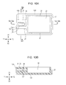
- Figs. 10A and 10B illustrate a configuration of a first cover 120 illustrated in Fig. 9 .
- Fig. 10A is a top view.
- Fig. 10B is a sectional view taken along line XB-XB illustrated in Fig. 10A .
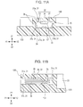
- Figs. 11A and 11B illustrate a configuration of a blade insertion slot 130 illustrated in Figs. 10A and 10B .
- Fig. 9 is an exploded perspective view illustrating the configuration of the vehicle key device 101 according to the second embodiment of the present invention.
- Figs. 10A and 10B illustrate a configuration of a first cover 120 illustrated in Fig. 9 .
- Fig. 10A is a top view.
- Fig. 10B is a sectional view taken along line XB-XB illustrated in Fig. 10A .
- Figs. 11A and 11B
- FIG. 11A is a sectional view taken along line XIA-XIA illustrated in Fig. 10A and illustrates a configuration around the blade insertion slot 130.
- Fig. 11B is a sectional view taken along line XIB-XIB illustrated in Fig. 10A and illustrates a configuration around the blade insertion slot 130.
- the vehicle key device 101 includes the key head portion 10 and the key blade 50 that is fastened to the key head portion 10.
- the key head portion 10 includes the first cover 120 and the second cover 40.
- the first cover 120 has the blade insertion slot 130.
- the first cover 120, the blade insertion slot 130, and the second cover 40 are made of a synthetic resin.
- the key blade 50 is made of metal.
- the blade insertion slot 130 includes five inner walls 31 including the upper wall 31a, the lower wall 31b, the left wall 31c, the right wall 31d, and the rear wall 31e; and the upper end portion 32 providing the upper wall 31a.
- the upper end portion 32 of the blade insertion slot 130 includes the pair of notches 33 and the elastic part 34.
- the elastic part 34 has the first projection 35 provided on the rear portion thereof.
- the upper wall 31a, the lower wall 31b, the left wall 31c, and the right wall 31d of the blade insertion slot 130 each have the plurality of second projections 36.
- the lower wall 31b of the blade insertion slot 130 has a substantially hemispherical third projection 131.
- the third projection 131 is made of a synthetic resin, as with the blade insertion slot 130.
- the lower wall 31b of the blade insertion slot 130 has the third projection 131, and not only the first projection 35 of the blade insertion slot 130 but also the third projection 131 of the blade insertion slot 130 engage with the through hole 52 of the key blade 50. Since the first projection 35 and the third projection 131 of the blade insertion slot 130 engage with the through hole 52 of the key blade 50, the force of preventing the key blade 50 from moving toward the front side is increased. Consequently, the key blade 50 is more effectively prevented from coming off the blade insertion slot 30 than in a case where only the first projection 35 of the blade insertion slot 130 engages with the through hole 52 of the key blade 50.
- the vehicle key device 1 (or the vehicle key device 101) may be used for any other purposes instead of the keyless entry system.
- the key head portion 10 may house any devices other than the electronic circuit for radio communication and the battery for power supply.
- the key head portion 10 may have any other external shape instead of that described above. Moreover, the key head portion 10 may be provided with any other devices in addition to those described above. For example, an operation switch for instructing the locking/unlocking of the doors of the vehicle may be provided on the surface of the key head portion 10.
- the first cover 20 (or the first cover 120), the blade insertion slot 30 (or the blade insertion slot 130), and the second cover 40 may each be made of any other material instead of a synthetic resin.
- the key blade 50 may be made of any other material instead of metal.
- the supporting portion 42 of the second cover 40 may have any other shape instead of that described above.
- the supporting portion 42 may be a projection projecting downward in such a manner as to press a predetermined part of the upper end portion 32 of the blade insertion slot 30.
- the first projection 35, the second projections 36, and the third projection 131 may have any other shapes instead of those described above.
- the first projection 35 may be a substantially hemispherical projection or a substantially truncated-conical projection
- the second projections 36 may each be replaced with a plurality of substantially hemispherical or substantially truncated-conical projections that are arranged in the anteroposterior direction
- the third projection 131 may be a substantially truncated-conical projection.
- only a portion of the rear wall 31e may serve as the contact surface with which the end surface 51e of the key blade 50 comes into contact.
Landscapes
- Engineering & Computer Science (AREA)
- Manufacturing & Machinery (AREA)
- Physics & Mathematics (AREA)
- General Physics & Mathematics (AREA)
- Lock And Its Accessories (AREA)
Applications Claiming Priority (1)
| Application Number | Priority Date | Filing Date | Title |
|---|---|---|---|
| JP2013254985A JP6032816B2 (ja) | 2013-12-10 | 2013-12-10 | 車両用キー装置 |
Publications (3)
| Publication Number | Publication Date |
|---|---|
| EP2884028A2 true EP2884028A2 (de) | 2015-06-17 |
| EP2884028A3 EP2884028A3 (de) | 2016-04-13 |
| EP2884028B1 EP2884028B1 (de) | 2017-10-18 |
Family
ID=52023193
Family Applications (1)
| Application Number | Title | Priority Date | Filing Date |
|---|---|---|---|
| EP14195406.5A Not-in-force EP2884028B1 (de) | 2013-12-10 | 2014-11-28 | Fahrzeugschlüsselvorrichtung |
Country Status (3)
| Country | Link |
|---|---|
| EP (1) | EP2884028B1 (de) |
| JP (1) | JP6032816B2 (de) |
| CN (1) | CN104695767B (de) |
Cited By (1)
| Publication number | Priority date | Publication date | Assignee | Title |
|---|---|---|---|---|
| EP3957810A1 (de) * | 2020-08-21 | 2022-02-23 | Alps Alpine Co., Ltd. | Tragbare vorrichtung |
Families Citing this family (2)
| Publication number | Priority date | Publication date | Assignee | Title |
|---|---|---|---|---|
| CN105781247A (zh) * | 2016-05-25 | 2016-07-20 | 上海万超汽车天窗有限公司 | 一种汽车点火用钥匙及其加工方法 |
| DE102017002122A1 (de) * | 2017-03-08 | 2018-09-13 | Huf Hülsbeck & Fürst Gmbh & Co. Kg | Kraftfahrzeugschlüssel |
Citations (1)
| Publication number | Priority date | Publication date | Assignee | Title |
|---|---|---|---|---|
| JP2007297775A (ja) | 2006-04-27 | 2007-11-15 | Alpha Corp | 解錠キー |
Family Cites Families (10)
| Publication number | Priority date | Publication date | Assignee | Title |
|---|---|---|---|---|
| US3729965A (en) * | 1971-04-29 | 1973-05-01 | K Gartner | Multiple part key for conventional locks |
| FR2244362A5 (de) * | 1973-09-17 | 1975-04-11 | Crasnianski France Sa | |
| DE3521417A1 (de) * | 1985-06-14 | 1986-05-28 | Waldemar 8701 Theilheim Müller | Schluesselbart-widerhakenkeil mit schablonenvorlage fuer griffbefestigung, besonders fuer kfz-zuendschluessel-signal-gehaeuse als gurtanlege-erinnerung |
| JPS6334862U (de) * | 1986-08-26 | 1988-03-05 | ||
| JP3138441B2 (ja) * | 1997-05-28 | 2001-02-26 | 有限会社信濃の國や | キー装着用のカバー |
| FR2777539B1 (fr) * | 1998-04-20 | 2000-06-23 | 3 D Dev | Dispositif presentant un boitier et une tige rigide, notamment une clef de vehicule automobile logeant une telecommande |
| FR2798417B1 (fr) * | 1999-09-09 | 2001-11-23 | Siemens Automotive Sa | Dispositif de telecommande pour le verrouillage/ deverrouillage des ouvrants d'un vehicule automobile |
| FR2838151A1 (fr) * | 2002-04-05 | 2003-10-10 | Valeo Securite Habitacle | Cle comportant des pattes de verrouillage longitudinal de la tige a l'interieur de la tete |
| CN101063384A (zh) * | 2006-04-29 | 2007-10-31 | 光阳工业股份有限公司 | 可拆卸的钥匙 |
| CN201100013Y (zh) * | 2007-08-27 | 2008-08-13 | 梁文顺 | 一种组合钥匙 |
-
2013
- 2013-12-10 JP JP2013254985A patent/JP6032816B2/ja active Active
-
2014
- 2014-11-28 EP EP14195406.5A patent/EP2884028B1/de not_active Not-in-force
- 2014-12-03 CN CN201410724546.1A patent/CN104695767B/zh active Active
Patent Citations (1)
| Publication number | Priority date | Publication date | Assignee | Title |
|---|---|---|---|---|
| JP2007297775A (ja) | 2006-04-27 | 2007-11-15 | Alpha Corp | 解錠キー |
Cited By (3)
| Publication number | Priority date | Publication date | Assignee | Title |
|---|---|---|---|---|
| EP3957810A1 (de) * | 2020-08-21 | 2022-02-23 | Alps Alpine Co., Ltd. | Tragbare vorrichtung |
| JP2022035844A (ja) * | 2020-08-21 | 2022-03-04 | アルプスアルパイン株式会社 | 携帯機 |
| JP7473421B2 (ja) | 2020-08-21 | 2024-04-23 | アルプスアルパイン株式会社 | 携帯機 |
Also Published As
| Publication number | Publication date |
|---|---|
| JP6032816B2 (ja) | 2016-11-30 |
| EP2884028A3 (de) | 2016-04-13 |
| CN104695767B (zh) | 2017-07-07 |
| CN104695767A (zh) | 2015-06-10 |
| JP2015113592A (ja) | 2015-06-22 |
| EP2884028B1 (de) | 2017-10-18 |
Similar Documents
| Publication | Publication Date | Title |
|---|---|---|
| US9293276B2 (en) | Electronic component assembly structure and electrical junction box | |
| EP1043685B1 (de) | IC Kartenrahmenbausatz und dazugehörige IC Karte | |
| EP2956275B1 (de) | Formkörper für eine elektrische vorrichtung und elektrische vorrichtung | |
| JP6602214B2 (ja) | プッシュスイッチ | |
| US20150027868A1 (en) | Button, button arrangement and electronic device employing same | |
| JP4330496B2 (ja) | 携帯端末機 | |
| EP2884028B1 (de) | Fahrzeugschlüsselvorrichtung | |
| KR101412485B1 (ko) | 압접형 커넥터 | |
| US20090242264A1 (en) | Two piece shielding device | |
| US10784619B2 (en) | Spring type connector | |
| KR102131989B1 (ko) | 카드용 커넥터 | |
| US10595421B2 (en) | Portable operation device | |
| US20130029200A1 (en) | Electronic device with detachable battery | |
| CN111370246B (zh) | 壳体组件及电子设备 | |
| US6566597B2 (en) | Shield assembly for computer enclosure and pressing machine for making it | |
| KR102276460B1 (ko) | 트레이 | |
| US20080120998A1 (en) | Laundry Device | |
| JP2011097262A (ja) | 遠隔操作携帯機 | |
| US7964811B2 (en) | Moisture-proof push-button switch module | |
| JP2015195091A (ja) | 電子機器及び電子機器のボタン構造 | |
| JP2013021158A (ja) | カバーの接続構造およびカバーの接続方法 | |
| EP3242312A1 (de) | Elektromagnetisches relais | |
| KR100639342B1 (ko) | 휴대폰의 유에스비 무선송수신 모듈 고정장치 | |
| JP2024168134A (ja) | 通信装置 | |
| JP2004342333A (ja) | 電子機器の電池カバーの取付け構造 |
Legal Events
| Date | Code | Title | Description |
|---|---|---|---|
| PUAI | Public reference made under article 153(3) epc to a published international application that has entered the european phase |
Free format text: ORIGINAL CODE: 0009012 |
|
| 17P | Request for examination filed |
Effective date: 20141128 |
|
| AK | Designated contracting states |
Kind code of ref document: A2 Designated state(s): AL AT BE BG CH CY CZ DE DK EE ES FI FR GB GR HR HU IE IS IT LI LT LU LV MC MK MT NL NO PL PT RO RS SE SI SK SM TR |
|
| AX | Request for extension of the european patent |
Extension state: BA ME |
|
| PUAL | Search report despatched |
Free format text: ORIGINAL CODE: 0009013 |
|
| AK | Designated contracting states |
Kind code of ref document: A3 Designated state(s): AL AT BE BG CH CY CZ DE DK EE ES FI FR GB GR HR HU IE IS IT LI LT LU LV MC MK MT NL NO PL PT RO RS SE SI SK SM TR |
|
| AX | Request for extension of the european patent |
Extension state: BA ME |
|
| RIC1 | Information provided on ipc code assigned before grant |
Ipc: E05B 19/04 20060101AFI20160308BHEP Ipc: E05B 19/10 20060101ALI20160308BHEP |
|
| R17P | Request for examination filed (corrected) |
Effective date: 20161011 |
|
| RBV | Designated contracting states (corrected) |
Designated state(s): AL AT BE BG CH CY CZ DE DK EE ES FI FR GB GR HR HU IE IS IT LI LT LU LV MC MK MT NL NO PL PT RO RS SE SI SK SM TR |
|
| GRAP | Despatch of communication of intention to grant a patent |
Free format text: ORIGINAL CODE: EPIDOSNIGR1 |
|
| INTG | Intention to grant announced |
Effective date: 20170606 |
|
| GRAS | Grant fee paid |
Free format text: ORIGINAL CODE: EPIDOSNIGR3 |
|
| GRAA | (expected) grant |
Free format text: ORIGINAL CODE: 0009210 |
|
| AK | Designated contracting states |
Kind code of ref document: B1 Designated state(s): AL AT BE BG CH CY CZ DE DK EE ES FI FR GB GR HR HU IE IS IT LI LT LU LV MC MK MT NL NO PL PT RO RS SE SI SK SM TR |
|
| REG | Reference to a national code |
Ref country code: GB Ref legal event code: FG4D |
|
| REG | Reference to a national code |
Ref country code: CH Ref legal event code: EP |
|
| REG | Reference to a national code |
Ref country code: AT Ref legal event code: REF Ref document number: 938094 Country of ref document: AT Kind code of ref document: T Effective date: 20171115 Ref country code: IE Ref legal event code: FG4D |
|
| REG | Reference to a national code |
Ref country code: DE Ref legal event code: R096 Ref document number: 602014015904 Country of ref document: DE |
|
| REG | Reference to a national code |
Ref country code: NL Ref legal event code: MP Effective date: 20171018 |
|
| REG | Reference to a national code |
Ref country code: LT Ref legal event code: MG4D |
|
| REG | Reference to a national code |
Ref country code: AT Ref legal event code: MK05 Ref document number: 938094 Country of ref document: AT Kind code of ref document: T Effective date: 20171018 |
|
| PG25 | Lapsed in a contracting state [announced via postgrant information from national office to epo] |
Ref country code: NL Free format text: LAPSE BECAUSE OF FAILURE TO SUBMIT A TRANSLATION OF THE DESCRIPTION OR TO PAY THE FEE WITHIN THE PRESCRIBED TIME-LIMIT Effective date: 20171018 |
|
| PG25 | Lapsed in a contracting state [announced via postgrant information from national office to epo] |
Ref country code: SE Free format text: LAPSE BECAUSE OF FAILURE TO SUBMIT A TRANSLATION OF THE DESCRIPTION OR TO PAY THE FEE WITHIN THE PRESCRIBED TIME-LIMIT Effective date: 20171018 Ref country code: FI Free format text: LAPSE BECAUSE OF FAILURE TO SUBMIT A TRANSLATION OF THE DESCRIPTION OR TO PAY THE FEE WITHIN THE PRESCRIBED TIME-LIMIT Effective date: 20171018 Ref country code: NO Free format text: LAPSE BECAUSE OF FAILURE TO SUBMIT A TRANSLATION OF THE DESCRIPTION OR TO PAY THE FEE WITHIN THE PRESCRIBED TIME-LIMIT Effective date: 20180118 Ref country code: ES Free format text: LAPSE BECAUSE OF FAILURE TO SUBMIT A TRANSLATION OF THE DESCRIPTION OR TO PAY THE FEE WITHIN THE PRESCRIBED TIME-LIMIT Effective date: 20171018 Ref country code: LT Free format text: LAPSE BECAUSE OF FAILURE TO SUBMIT A TRANSLATION OF THE DESCRIPTION OR TO PAY THE FEE WITHIN THE PRESCRIBED TIME-LIMIT Effective date: 20171018 |
|
| PG25 | Lapsed in a contracting state [announced via postgrant information from national office to epo] |
Ref country code: GR Free format text: LAPSE BECAUSE OF FAILURE TO SUBMIT A TRANSLATION OF THE DESCRIPTION OR TO PAY THE FEE WITHIN THE PRESCRIBED TIME-LIMIT Effective date: 20180119 Ref country code: LV Free format text: LAPSE BECAUSE OF FAILURE TO SUBMIT A TRANSLATION OF THE DESCRIPTION OR TO PAY THE FEE WITHIN THE PRESCRIBED TIME-LIMIT Effective date: 20171018 Ref country code: HR Free format text: LAPSE BECAUSE OF FAILURE TO SUBMIT A TRANSLATION OF THE DESCRIPTION OR TO PAY THE FEE WITHIN THE PRESCRIBED TIME-LIMIT Effective date: 20171018 Ref country code: RS Free format text: LAPSE BECAUSE OF FAILURE TO SUBMIT A TRANSLATION OF THE DESCRIPTION OR TO PAY THE FEE WITHIN THE PRESCRIBED TIME-LIMIT Effective date: 20171018 Ref country code: BG Free format text: LAPSE BECAUSE OF FAILURE TO SUBMIT A TRANSLATION OF THE DESCRIPTION OR TO PAY THE FEE WITHIN THE PRESCRIBED TIME-LIMIT Effective date: 20180118 Ref country code: AT Free format text: LAPSE BECAUSE OF FAILURE TO SUBMIT A TRANSLATION OF THE DESCRIPTION OR TO PAY THE FEE WITHIN THE PRESCRIBED TIME-LIMIT Effective date: 20171018 Ref country code: IS Free format text: LAPSE BECAUSE OF FAILURE TO SUBMIT A TRANSLATION OF THE DESCRIPTION OR TO PAY THE FEE WITHIN THE PRESCRIBED TIME-LIMIT Effective date: 20180218 |
|
| REG | Reference to a national code |
Ref country code: DE Ref legal event code: R097 Ref document number: 602014015904 Country of ref document: DE |
|
| PG25 | Lapsed in a contracting state [announced via postgrant information from national office to epo] |
Ref country code: DK Free format text: LAPSE BECAUSE OF FAILURE TO SUBMIT A TRANSLATION OF THE DESCRIPTION OR TO PAY THE FEE WITHIN THE PRESCRIBED TIME-LIMIT Effective date: 20171018 Ref country code: CZ Free format text: LAPSE BECAUSE OF FAILURE TO SUBMIT A TRANSLATION OF THE DESCRIPTION OR TO PAY THE FEE WITHIN THE PRESCRIBED TIME-LIMIT Effective date: 20171018 Ref country code: EE Free format text: LAPSE BECAUSE OF FAILURE TO SUBMIT A TRANSLATION OF THE DESCRIPTION OR TO PAY THE FEE WITHIN THE PRESCRIBED TIME-LIMIT Effective date: 20171018 Ref country code: SK Free format text: LAPSE BECAUSE OF FAILURE TO SUBMIT A TRANSLATION OF THE DESCRIPTION OR TO PAY THE FEE WITHIN THE PRESCRIBED TIME-LIMIT Effective date: 20171018 Ref country code: LI Free format text: LAPSE BECAUSE OF NON-PAYMENT OF DUE FEES Effective date: 20171130 Ref country code: CH Free format text: LAPSE BECAUSE OF NON-PAYMENT OF DUE FEES Effective date: 20171130 Ref country code: MC Free format text: LAPSE BECAUSE OF FAILURE TO SUBMIT A TRANSLATION OF THE DESCRIPTION OR TO PAY THE FEE WITHIN THE PRESCRIBED TIME-LIMIT Effective date: 20171018 |
|
| PLBE | No opposition filed within time limit |
Free format text: ORIGINAL CODE: 0009261 |
|
| STAA | Information on the status of an ep patent application or granted ep patent |
Free format text: STATUS: NO OPPOSITION FILED WITHIN TIME LIMIT |
|
| PG25 | Lapsed in a contracting state [announced via postgrant information from national office to epo] |
Ref country code: RO Free format text: LAPSE BECAUSE OF FAILURE TO SUBMIT A TRANSLATION OF THE DESCRIPTION OR TO PAY THE FEE WITHIN THE PRESCRIBED TIME-LIMIT Effective date: 20171018 Ref country code: IT Free format text: LAPSE BECAUSE OF FAILURE TO SUBMIT A TRANSLATION OF THE DESCRIPTION OR TO PAY THE FEE WITHIN THE PRESCRIBED TIME-LIMIT Effective date: 20171018 Ref country code: SM Free format text: LAPSE BECAUSE OF FAILURE TO SUBMIT A TRANSLATION OF THE DESCRIPTION OR TO PAY THE FEE WITHIN THE PRESCRIBED TIME-LIMIT Effective date: 20171018 Ref country code: PL Free format text: LAPSE BECAUSE OF FAILURE TO SUBMIT A TRANSLATION OF THE DESCRIPTION OR TO PAY THE FEE WITHIN THE PRESCRIBED TIME-LIMIT Effective date: 20171018 Ref country code: LU Free format text: LAPSE BECAUSE OF NON-PAYMENT OF DUE FEES Effective date: 20171128 |
|
| REG | Reference to a national code |
Ref country code: FR Ref legal event code: ST Effective date: 20180731 Ref country code: BE Ref legal event code: MM Effective date: 20171130 |
|
| REG | Reference to a national code |
Ref country code: IE Ref legal event code: MM4A |
|
| 26N | No opposition filed |
Effective date: 20180719 |
|
| PG25 | Lapsed in a contracting state [announced via postgrant information from national office to epo] |
Ref country code: MT Free format text: LAPSE BECAUSE OF NON-PAYMENT OF DUE FEES Effective date: 20171128 |
|
| PG25 | Lapsed in a contracting state [announced via postgrant information from national office to epo] |
Ref country code: IE Free format text: LAPSE BECAUSE OF NON-PAYMENT OF DUE FEES Effective date: 20171128 Ref country code: FR Free format text: LAPSE BECAUSE OF NON-PAYMENT OF DUE FEES Effective date: 20171218 |
|
| PG25 | Lapsed in a contracting state [announced via postgrant information from national office to epo] |
Ref country code: SI Free format text: LAPSE BECAUSE OF FAILURE TO SUBMIT A TRANSLATION OF THE DESCRIPTION OR TO PAY THE FEE WITHIN THE PRESCRIBED TIME-LIMIT Effective date: 20171018 Ref country code: BE Free format text: LAPSE BECAUSE OF NON-PAYMENT OF DUE FEES Effective date: 20171130 |
|
| REG | Reference to a national code |
Ref country code: DE Ref legal event code: R082 Ref document number: 602014015904 Country of ref document: DE Representative=s name: SCHMITT-NILSON SCHRAUD WAIBEL WOHLFROM PATENTA, DE Ref country code: DE Ref legal event code: R081 Ref document number: 602014015904 Country of ref document: DE Owner name: ALPS ALPINE CO., LTD., JP Free format text: FORMER OWNER: ALPS ELECTRIC CO., LTD, TOKYO, JP |
|
| PG25 | Lapsed in a contracting state [announced via postgrant information from national office to epo] |
Ref country code: HU Free format text: LAPSE BECAUSE OF FAILURE TO SUBMIT A TRANSLATION OF THE DESCRIPTION OR TO PAY THE FEE WITHIN THE PRESCRIBED TIME-LIMIT; INVALID AB INITIO Effective date: 20141128 |
|
| GBPC | Gb: european patent ceased through non-payment of renewal fee |
Effective date: 20181128 |
|
| PG25 | Lapsed in a contracting state [announced via postgrant information from national office to epo] |
Ref country code: CY Free format text: LAPSE BECAUSE OF FAILURE TO SUBMIT A TRANSLATION OF THE DESCRIPTION OR TO PAY THE FEE WITHIN THE PRESCRIBED TIME-LIMIT Effective date: 20171018 |
|
| PG25 | Lapsed in a contracting state [announced via postgrant information from national office to epo] |
Ref country code: MK Free format text: LAPSE BECAUSE OF FAILURE TO SUBMIT A TRANSLATION OF THE DESCRIPTION OR TO PAY THE FEE WITHIN THE PRESCRIBED TIME-LIMIT Effective date: 20171018 |
|
| PG25 | Lapsed in a contracting state [announced via postgrant information from national office to epo] |
Ref country code: GB Free format text: LAPSE BECAUSE OF NON-PAYMENT OF DUE FEES Effective date: 20181128 |
|
| PGFP | Annual fee paid to national office [announced via postgrant information from national office to epo] |
Ref country code: DE Payment date: 20191121 Year of fee payment: 6 |
|
| PG25 | Lapsed in a contracting state [announced via postgrant information from national office to epo] |
Ref country code: TR Free format text: LAPSE BECAUSE OF FAILURE TO SUBMIT A TRANSLATION OF THE DESCRIPTION OR TO PAY THE FEE WITHIN THE PRESCRIBED TIME-LIMIT Effective date: 20171018 |
|
| PG25 | Lapsed in a contracting state [announced via postgrant information from national office to epo] |
Ref country code: PT Free format text: LAPSE BECAUSE OF FAILURE TO SUBMIT A TRANSLATION OF THE DESCRIPTION OR TO PAY THE FEE WITHIN THE PRESCRIBED TIME-LIMIT Effective date: 20171018 |
|
| PG25 | Lapsed in a contracting state [announced via postgrant information from national office to epo] |
Ref country code: AL Free format text: LAPSE BECAUSE OF FAILURE TO SUBMIT A TRANSLATION OF THE DESCRIPTION OR TO PAY THE FEE WITHIN THE PRESCRIBED TIME-LIMIT Effective date: 20171018 |
|
| REG | Reference to a national code |
Ref country code: DE Ref legal event code: R119 Ref document number: 602014015904 Country of ref document: DE |
|
| PG25 | Lapsed in a contracting state [announced via postgrant information from national office to epo] |
Ref country code: DE Free format text: LAPSE BECAUSE OF NON-PAYMENT OF DUE FEES Effective date: 20210601 |