EP2883779A1 - Anzeigedeckel - Google Patents
Anzeigedeckel Download PDFInfo
- Publication number
- EP2883779A1 EP2883779A1 EP13837699.1A EP13837699A EP2883779A1 EP 2883779 A1 EP2883779 A1 EP 2883779A1 EP 13837699 A EP13837699 A EP 13837699A EP 2883779 A1 EP2883779 A1 EP 2883779A1
- Authority
- EP
- European Patent Office
- Prior art keywords
- heating element
- cover body
- cover
- display
- transparent heating
- Prior art date
- Legal status (The legal status is an assumption and is not a legal conclusion. Google has not performed a legal analysis and makes no representation as to the accuracy of the status listed.)
- Withdrawn
Links
Images




Classifications
-
- B—PERFORMING OPERATIONS; TRANSPORTING
- B61—RAILWAYS
- B61L—GUIDING RAILWAY TRAFFIC; ENSURING THE SAFETY OF RAILWAY TRAFFIC
- B61L5/00—Local operating mechanisms for points or track-mounted scotch-blocks; Visible or audible signals; Local operating mechanisms for visible or audible signals
- B61L5/12—Visible signals
- B61L5/18—Light signals; Mechanisms associated therewith, e.g. blinders
- B61L5/1809—Daylight signals
- B61L5/1881—Wiring diagrams for power supply, control or testing
-
- B—PERFORMING OPERATIONS; TRANSPORTING
- B61—RAILWAYS
- B61L—GUIDING RAILWAY TRAFFIC; ENSURING THE SAFETY OF RAILWAY TRAFFIC
- B61L5/00—Local operating mechanisms for points or track-mounted scotch-blocks; Visible or audible signals; Local operating mechanisms for visible or audible signals
- B61L5/12—Visible signals
- B61L5/18—Light signals; Mechanisms associated therewith, e.g. blinders
Definitions
- the present invention relates to a display cover.
- a display in which a display unit is disposed on the front surface of a body portion as described in, for example, PTL 1 is known.
- the display is provided with an awning which protrudes forward from the body portion to cover the display unit from above.
- the awning is provided with a heater for melting snow.
- snow accumulation on the awning is not suppressed and snow lumps may be formed on the awning.
- snow lumps grow and cover the display unit from the front, and thus it is also difficult to secure the visibility of the display unit.
- increasing the heating value of the heater may be considered. However, in this case, a large amount of energy is consumed.
- the present invention has been made taking the foregoing circumstances into consideration, and an object thereof is to provide a display cover capable of more reliably securing the visibility of a display unit while suppressing energy consumption.
- a display cover which is attached to a display including a body portion and a display unit disposed on a front surface of the body portion, the display cover including: a cylindrical cover body which is disposed on the front surface of the body portion, is formed to surround the display unit in a front view in which the display cover is viewed from the front, and has an open front end; and a transparent heating element which is configured to block the front end and to form a cover inner space with the display and the cover body.
- the display unit of the display is visible through the transparent heating element from the front.
- the display unit is covered with the cover body and the transparent heating element, snow accumulation on the display unit can be suppressed.
- snow accumulation on the transparent heating element can also be suppressed.
- the air in the inner space of the cover body is also heated by the transparent heating element. Therefore, the transparent heating element can also heat the cover body via the air in the inner space of the cover body, and thus snow accumulation on the cover body can also be suppressed.
- the air heated in the inner space of the cover body rises in the inner space of the cover body and heats an upper wall section in the cover body, and thus snow accumulation on the upper wall section can be effectively suppressed.
- snow accumulation on the cover body can be suppressed, snow lumps on the cover body can be prevented from growing and covering the display unit.
- the visibility of the display unit can be reliably secured. Furthermore, by heating the transparent heating element, both of snow accumulation on the transparent heating element and snow accumulation on the cover body can be suppressed, and thus energy consumption can also be suppressed.
- the transparent heating element may include a substrate portion fitted to the front end of the cover body, and a film portion which is laminated on the substrate portion and has at least a portion forming a heating region.
- the transparent heating element is provided with the substrate portion and the film portion and the heating region of the film portion is provided over a wide range of the substrate portion, the transparent heating element can be easily heated in a wide range without unevenness. Therefore, snow accumulation on the transparent heating element can be reliably suppressed.
- the transparent heating element can be easily heated in a wide range without unevenness. Therefore, compared to, for example, a configuration in which a heating wire as a heat source is disposed in a substrate portion, the substrate portion can be prevented from locally having a high temperature. Accordingly, restrictions on heat resistance conditions required of the material forming the substrate portion can be relaxed and thus various materials can be employed as the material forming the substrate portion.
- the display cover according to the aspect of the present invention may further include an end portion heating element which heats a front end surface formed at a front end edge of the cover body.
- the end portion heating element which heats the front end surface of the cover body is provided, even when snow lumps on the cover body grow in a direction toward the transparent heating element, the growth of snow lumps on the front end surface of the cover body can be easily prevented by the end portion heating element. Accordingly, snow lumps on the cover body can be reliably prevented from growing and covering the display unit, and thus the visibility of the display unit can be more reliably secured.
- the end portion heating element heats the front end surface of the cover body over the entire periphery of the front end surface
- the end portion heating element heats the front end surface of the cover body and thus the outer peripheral edge portion of the layer of snow can be melted over the entire periphery. Accordingly, the layer of snow can be removed from the display cover and thus the visibility of the display unit can be more reliably secured.
- the front end of the cover body may be open obliquely downward in a forward direction, and the transparent heating element may extend to be gradually directed toward a rear side moving downward from above.
- the front end opening of the cover body is open obliquely downward in the forward direction and the transparent heating element extends rearward moving downward from above. Therefore, even when snow accumulation on the transparent heating element occurs, the snow moves downward along the front surface of the transparent heating element or falls from the transparent heating element, for example, under its own weight, and thus the visibility of the display unit can be more reliably secured.
- the transparent heating element gradually extends rearward downward from above, for example, compared to a case where the transparent heating element straightly extends downward from above, the upper wall section of the cover body can be reliably heated by the air in the inner space of the cover body heated by the transparent heating element, and thus snow accumulation on the upper wall section can further be effectively suppressed.
- the cover body may further include a front flange portion which is provided in the front end and protrudes inward in a radial direction of the cover body in the front view
- the transparent heating element may be formed in a plate shape and has an outer peripheral edge portion, the outer peripheral edge portion being fixed to the front flange portion by a sealing material
- a cutout portion having a cutout surface may be formed at a position close to the front flange portion on a front side of the outer peripheral edge portion of the transparent heating element
- the sealing material may be disposed to be buried in the cutout portion between the cutout surface and the front flange portion.
- the cutout portion in which the front flange portion is disposed is formed in the outer peripheral edge portion of the transparent heating element, while holding the transparent heating element by supporting the cutout surface with the front flange portion from the front, the front end surface of the cover body can be prevented from significantly protruding from the front surface of the transparent heating element. Accordingly, a large stepped portion can be prevented from being formed between the front surface of the transparent heating element and the front end surface of the cover body, and snow accumulation on the display cover can be effectively suppressed.
- the sealing material is disposed to be buried between the cutout surface of the cutout portion and the front flange portion, the sealing material can be prevented from being swollen forward from the front end surface of the cover body while the cutout surface and the front flange portion are firmly fixed to each other by the sealing material. Accordingly, a large stepped portion can be prevented from being formed between the sealing material and the front end surface of the cover body, and thus snow accumulation on the display cover can be more effectively suppressed.
- the display cover according to the aspect of the present invention may further include an upper wall heating element disposed in an upper wall section of the cover body.
- the upper wall heating element disposed in the upper wall section of the cover body is provided, by heating the upper wall heating element, snow accumulation on the upper wall section of the cover body can be reliably suppressed.
- the heating of the transparent heating element can also suppress snow accumulation on the upper wall section, snow accumulation on the upper wall section can be reliably suppressed while also suppressing energy consumed by the upper wall heating element.
- the upper wall heating element disposed in the upper wall section of the cover body is provided, even when snow lumps on the upper wall section of the cover body grow downward, the body portions of the snow lumps positioned on the upper wall section can be melted by the upper wall heating element, and grown portions of the snow lumps growing from the body portions can be caused to fall from the cover body. Therefore, the visibility of the display unit can be more reliably secured.
- the visibility of the display unit can be reliably secured while suppressing energy consumption.
- a display device 10 includes a signal device (display) 20 and a signal device cover (display cover) 30.
- the signal device 20 is used as, for example, a railway traffic signal.
- the signal device 20 displays information whose contents are changed.
- the signal device 20 includes a body portion 21 and a display unit 22 disposed on the front surface of the body portion 21.
- the body portion 21 is elongated in the vertical direction, and the size of the body portion 21 in the vertical direction is greater than any of the size of the body portion 21 in the forward and rearward directions and the size of the body portion 21 in the left and right directions.
- the front end portion of the body portion 21 is provided with a collar portion 21a which extends over the entire periphery of the body portion 21 and protrudes outward from the front end portion.
- the display unit 22 includes signal lights 22a which can be lit on and off. A plurality of the signal lights 22a are arranged in the vertical direction. The colors of light emitted by the signal lights 22a vary with the signal lights 22a.
- the display unit 22 is visible through a transparent heating element 32, which will be described later, of the signal device cover 30 from the front.
- upper side indicates the upper side in the vertical direction
- lower side indicates the lower side in the vertical direction
- front side indicates a side where the signal lights are visible
- rear side indicates the side opposite to the side where the signal lights are visible.
- left and right directions indicate the lateral direction of the display device 10 when the display device 10 is viewed from the side where the signal lights are visible.
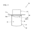
- the signal device cover 30 is attached to the signal device 20. As shown in FIGS. 1 to 7 , the signal device cover 30 includes a cover body 31, the transparent heating element 32, an end portion heating element 33, and an upper wall heating element 34.
- the cover body 31 is disposed on the front surface of the body portion 21 of the signal device 20 and is formed in a cylindrical shape to surround the display unit 22 in a front view in which the signal device cover 30 is viewed from the front, and the front end thereof is open.
- the cover body 31 surrounds the display unit 22 so that all of the plurality of signal lights 22a are disposed on the inside of the cover body 31 in the front view.
- the cover body 31 protrudes forward from the body portion 21 of the signal device 20.
- the rear end opening portion of the cover body 31 is blocked by the body portion 21.
- fixed pieces 35 are provided to protrude toward the inside of the cover body.
- the fixed pieces 35 are disposed at positions that avoid the signal lights 22a (positions that do not overlap the signal lights 22a) in the front view.
- screw holes which are open rearward are formed in the fixed pieces 35. Bolts (not shown) which are inserted into the collar portion 21a from the rear side are screwed to the screw holes. Accordingly, the signal device cover 30 is detachably attached to the signal device 20.
- An upper wall section 36 of the cover body 31 extends to be gradually directed toward the lower side moving toward the outside from the center portion of the left and right directions.
- the upper wall section 36 is curved to be convex upward in the front view.
- the rear end portion of the upper wall section 36 is depressed downward from the section that is positioned closer to the front side than the rear end portion of the upper wall section 36, and on the rear end portion of the upper wall section 36, a depressed portion 36a which is open upward is provided.
- the depressed portion 36a has a rectangular shape in a side view in which the signal device cover 30 is viewed from the side (the left and right directions).
- the side of a bottom wall section 37 of the cover body 31 in the left and right directions is the same as the size of the upper wall section 36 in the left and right directions.
- the bottom wall section 37 straightly extends in the left and right directions in the front view.
- the front end portion of the bottom wall section 37 protrudes downward from a base wall portion 37a which is positioned closer to the rear side than the front end portion in the bottom wall section 37.
- the front end portion of the bottom wall section 37 includes an end wall portion 37b positioned closer to the lower side than the base wall portion 37a and a connection wall portion 37c which connects the end wall portion 37b to the base wall portion 37a.
- the base wall portion 37a and the end wall portion 37b are parallel to each other.
- a front flange portion 38 and a rear flange portion 39 which protrude inward in the radial direction of the cover body 31 are provided.
- the front flange portion 38 is formed at the front end edge of the cover body 31 in an annular shape. A surface of the front flange portion 38 which is directed toward the front side forms a front end surface 31a of the cover body 31.
- the rear flange portion 39 is positioned closer to the rear side than the front flange portion 38.
- the protruding amount of the rear flange portion 39 is larger than the protruding amount of the front flange portion 38.
- the rear flange portion 39 is parallel to the front flange portion 38.
- the rear flange portion 39 is provided to have an inverted-U shape in the front view.
- the rear flange portion 39 is disposed at the upper wall section 36 and a pair of side wall sections 40 of the cover body 31.
- the lower end of the rear flange portion 39 is connected to the connection wall portion 37c of the bottom wall section 37 of the cover body 31.
- annular groove 41 is provided in the front end portion of the cover body 31 in the front end portion of the cover body 31 in the front end portion of the cover body 31.
- the annular groove 41 is formed on the inner peripheral surface of the front end portion of the cover body 31.
- the annular groove 41 is formed over the entire periphery of the cover body 31.
- the annular groove 41 is formed between the front flange portion 38, and the rear flange portion 39 or the connection wall portion 37c.
- a front end opening 31b which is an open front end of the cover body 31 is open obliquely downward on the front side.
- the front end surface 31a of the cover body 31 extends to be gradually directed toward the rear side moving downward from above in the side view.
- the upper wall heating element 34 which heats the upper wall is disposed in the upper wall section 36 of the cover body 31.
- the upper wall heating element 34 is disposed in a plate shape along the inner peripheral portion of the upper wall section 36 of the cover body 31.
- the upper wall heating element 34 is curved to be convex upward in the front view.
- the upper wall heating element 34 is disposed closer to the front side than the depressed portion 36a in the upper wall section 36.
- the upper wall heating element 34 is supported against the upper wall section 36 by a support member provided in the inner peripheral surface of the cover body 31.
- a configuration in which a heating wire is embedded in a heat transfer substrate may be employed.
- the material of the heating wire for example, a nichrome wire (registered trademark) may be employed.
- the end portion heating element 33 heats the front end surface 31a (the front flange portion 38) formed in the cover body 31 in an annular shape.
- the end portion heating element 33 heats the front end surface 31a (the front flange portion 38) of the cover body 31 over the entire periphery thereof.
- the end portion heating element 33 is formed over the entire periphery of the cover body 31.
- the end portion heating element 33 is disposed on the rear side of the front flange portion 38 of the cover body 31 and is fitted in the annular groove 41.
- a heating wire or the like coated with a tubular insulating member may be employed.
- the transparent heating element 32 blocks the front end opening 31b of the cover body 31.
- the transparent heating element 32 extends to be gradually directed toward the rear side moving downward from above.
- the transparent heating element 32 extends in a straight line shape in the side view and is inclined with respect to the collar portion 21a of the signal device 20.
- the transparent heating element 32 is disposed so as not to protrude forward from the front end opening 31b of the cover body 31.
- the lower end portion of the transparent heating element 32 is disposed closer to the lower side than the base wall portion 37a of the bottom wall section 37 of the cover body 31.
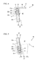
- the transparent heating element 32 is formed in a plate shape and the outer peripheral edge portion thereof is fixed to the front flange portion 38, the rear flange portion 39, and the connection wall portion 37c by a sealing material S.
- the outer peripheral edge portion of the transparent heating element 32 is supported by the front flange portion 38 of the cover body 31 from the front and is supported by the rear flange portion 39 and the connection wall portion 37c from the rear.
- the outer peripheral edge portion of the transparent heating element 32 is connected to the cover body 31 over the entire periphery of the cover body 31 by the sealing material S.
- the transparent heating element 32, the signal device 20, and the cover body 31 form a cover inner space 42.
- a cutout portion 32b is formed at a position close to the front flange portion 38 on the front side of the outer peripheral edge portion of the transparent heating element 32.
- the cutout portion 32b is formed over the entire periphery of the outer peripheral edge portion.
- a cutout surface 32c of the cutout portion 32b is formed by connecting a first surface which faces the front side and a second surface which faces the outside in the radial direction via an angular portion.
- the inner peripheral edge portion of the front flange portion 38 is disposed.
- the sealing material S is disposed to be buried between the cutout surface 32c and the upper wall heating element 38 in the cutout portion 32b.
- the sealing material S is not swollen forward from the front end surface 31 a of the cover body 31.
- the sealing material S is disposed to be buried between the outer peripheral edge portion of the rear surface of the transparent heating element 32 and the rear flange portion 39.
- a front surface 32a of the transparent heating element 32 and the front end surface 31a of the cover body 31 are positioned to be on substantially the same plane.
- the front surface 32a of the transparent heating element 32 is positioned slightly rearward from the front end surface 31a of the cover body 31.
- the transparent heating element 32 includes a substrate portion 43 fitted in the front end opening 31b of the cover body 31, and a film portion 44 laminated on one surface of the substrate portion 43.
- the substrate portion 43 may be formed of, for example, a resin material. Examples of the resin material include a polycarbonate resin.
- a coating layer (not shown) which protects the substrate portion 43 and a primer layer (not shown) which increases the adhesion between the coating layer and the substrate portion 43 may also be formed.
- the film portion 44 is formed on the rear surface of the substrate portion 43 over the entire surface of the rear surface thereof.
- the film portion 44 has a laminated structure.
- the film portion 44 is formed by laminating a buffer layer, a conductive film, and a protection layer (not shown) on the rear surface of the substrate portion 43 in this order.
- the conductive film is supplied with power and generates heat.
- the conductive film may be formed of, for example, indium tin oxide (ITO).
- ITO indium tin oxide
- the buffer layer is disposed between the substrate portion 43 and the conductive film.
- the buffer layer absorbs differences of thermal expansion and contraction between the substrate portion 43 and the conductive film.
- the buffer layer may be formed of, for example, titanium oxide (TiO 2 ), niobium pentoxide (Nb 2 O 5 ), or a material including the two.
- the protection layer is formed on the rear surface of the conductive film and protects the conductive film.
- the protection layer may be formed of, for example, an acrylic silicone resin, an acrylic urethane resin, or a material including the two.
- a pair of electrodes 45 which supply power to the conductive film are disposed at an interval in the left and right directions. Both of the electrodes 45 are provided between the conductive film and the protection film. Both of the electrodes 45 are disposed on the conductive film and are covered by the protection layer to be protected. In addition, in the film portion 44, a section (region) positioned between the two electrodes 45 forms a heating region 44a.
- the heating region 44a is disposed at a position (on the front side of the display unit 22) that overlaps the display unit 22 of the signal device 20 in the film portion 44 in the front view.
- the heating region 44a is disposed to cover the entirety of the display unit 22 (in the shown example, all of the signal lights 22a).
- the lower end of the heating region 44a is positioned closer to the lower side than the display unit 22 and is positioned closer to the lower side than the base wall portion 37a of the bottom wall section 37 of the cover body 31.
- the upper end of the heating region 44a is positioned closer to the upper side than the display unit 22 and is positioned closer to the upper side than the lower end of the upper wall heating element 34.
- the heating region 44a is disposed closer to the inside than the outer peripheral edge portion of the transparent heating element 32.
- the transparent heating element 32 has a sufficiently high light beam transmittance to secure visibility. That is, the transparent heating element 32 has transparency at a degree such that the display unit 22 is visible through the transparent heating element 32 when the signal device cover 30 is viewed from the front.
- a heating resin substrate described in Japanese Unexamined Patent Application, First Publication No. 2008-41343 may be employed.
- the heating temperatures of the transparent heating element 32, the end portion heating element 33, and the upper wall heating element 34 can be adjusted.
- the transparent heating element 32, the end portion heating element 33, and the upper wall heating element 34 are supplied with power from a power source (not shown) and generate heat.
- the power source is controlled by a power source controller (not shown).
- the power source controller may be provided with, for example, a thermostat and may control power supply depending on the outside air temperature, the temperature of the cover inner space 42, and the like.
- the signal device 20 may be supplied with power from the power source or may be supplied with power from a different power source from the power source.
- the display unit 22 is covered with the cover body 31 and the transparent heating element 32, snow accumulation on the display unit 22 can be suppressed.
- the transparent heating element 32 can also heat the cover body 31 via the air in the cover inner space 42, and thus snow accumulation on the cover body 31 can also be suppressed.
- the air heated in the cover inner space 42 rises in the cover inner space 42 and heats the upper wall section 36 in the cover body 31, and thus snow accumulation on the upper wall section 36 can be effectively suppressed.
- snow accumulation on the cover body 31 can be suppressed, snow lumps on the cover body 31 can be prevented from growing and covering the display unit 22.
- the visibility of the display unit 22 can be more reliably secured. Furthermore, by heating the transparent heating element 32, both of snow accumulation on the transparent heating element 32 and snow accumulation on the cover body 31 can be suppressed, and thus energy consumption can also be suppressed.
- the transparent heating element 32 is provided with the substrate portion 43 and the film portion 44 and the heating region 44a of the film portion 44 is provided over a wide range of the substrate portion 43, the transparent heating element 32 can be heated in a wide range without unevenness, and thus snow accumulation on the transparent heating element 32 can be reliably suppressed.
- the transparent heating element 32 can be heated in a wide range without unevenness, compared to, for example, a configuration in which a heating wire as a heat source is disposed in a substrate portion, the substrate portion 43 can be prevented from locally having a high temperature. Accordingly, restrictions on heat resistance conditions required of the material forming the substrate portion 43 can be relaxed and thus various materials can be employed as the material forming the substrate portion 43.
- the upper wall heating element 34 disposed in the upper wall section 36 of the cover body 31 is provided, by heating the upper wall heating element 34, snow accumulation on the upper wall section 36 of the cover body 31 can be reliably suppressed.
- the heating of the transparent heating element 32 can also suppress snow accumulation on the upper wall section 36, snow accumulation on the upper wall section 36 can be reliably suppressed while suppressing energy consumed by the upper wall heating element 34.
- the upper wall heating element 34 disposed in the upper wall section 36 of the cover body 31 is provided, even when snow lumps on the upper wall section 36 of the cover body 31 grow downward, the body portions of the snow lumps positioned on the upper wall section 36 can be melted by the upper wall heating element 34. Therefore, the snow lumps formed to protrude from the wall section 36 can be caused to fall from the cover body 31, and thus the visibility of the display unit 22 can be more reliably secured.
- the end portion heating element 33 which heats the front end surface 31a of the cover body 31 is provided, even when snow lumps on the cover body 31 are formed to protrude toward the transparent heating element 32, formation of snow lumps on the front end surface 31a of the cover body 31 can be easily prevented by the end portion heating element 33. Accordingly, snow lumps on the cover body 31 can be prevented from growing and covering the display unit 22, and thus the visibility of the display unit 22 can be more reliably secured.
- the end portion heating element 33 heats the front end surface 31a of the cover body 31 and thus the outer peripheral edge portion of the layer of snow can be melted over the entire periphery. Accordingly, the layer of snow can be removed from the signal device cover 30 and thus the visibility of the display unit 22 can be more reliably secured.
- the front end opening 31b of the cover body 31 is open obliquely downward in the forward direction and the transparent heating element 32 extends rearward moving downward from above, even when snow accumulation on the transparent heating element 32 occurs, the snow moves downward along the front surface 32a of the transparent heating element 32 or falls from the transparent heating element 32, for example, under its own weight, and thus the visibility of the display unit 22 can be more reliably secured.
- the lower end portion of the transparent heating element 32 is positioned closer to the lower side than the base wall portion 37a, even when snow that moves downward along the front surface 32a of the transparent heating element 32 does not fall from the lower end portion of the transparent heating element 32, an effect of the snow that remains on the lower end portion on the visibility of the display unit 22 can be suppressed, and thus the visibility can further be secured.
- the transparent heating element 32 extends rearward moving downward from above, for example, compared to a case where the transparent heating element 32 straightly extends downward from above, the upper wall section 36 of the cover body 31 can be reliably heated by the air in the cover inner space 42 heated by the transparent heating element 32, and thus snow accumulation on the upper wall section 36 can further be effectively suppressed.
- the cutout portion 32b is formed in the outer peripheral edge portion of the transparent heating element 32, while holding the transparent heating element 32 by supporting the cutout surface 32c with the front flange portion 38 from the front, the front end surface 31a of the cover body 31 can be prevented from largely protruding from the front surface 32a of the transparent heating element 32. Accordingly, a large stepped portion can be prevented from being formed in the vicinity of the boundary between the front surface 32a of the transparent heating element 32 and the front end surface 31a of the cover body 31, and snow accumulation on the signal device cover 30 can be effectively suppressed.
- the sealing material S is disposed to be buried between the cutout surface 32c of the cutout portion 32b and the front flange portion 38, the sealing material S can be prevented from being swollen forward from the front end surface 31a of the cover body 31 while the cutout surface 32c and the front flange portion 38 are firmly fixed to each other by the sealing material S. Accordingly, a large stepped portion can be prevented from being formed in the vicinity of the boundary between the sealing material S and the front end surface 31a of the cover body 31, and thus snow accumulation on the signal device cover 30 can be more effectively suppressed.
- the transparent heating element 32 is disposed in the front end opening 31b of the cover body 31 (the front surface 32a of the transparent heating element 32 and the front end surface 31a of the cover body 31 are positioned on substantially the same plane), for example, the transparent heating element can effectively suppress snow accumulation on the signal device cover 30.
- the upper wall heating element 34 may not be provided.
- the heating region 44a of the film portion 44 is not limited to the above-described embodiment, and at least a portion of the film portion may be formed as the heating region. Otherwise, for example, the heating region may be provided over the entire surface of the film portion.
- the film portion 44 is formed on the rear surface of the substrate portion 43.
- the film portion 44 is not limited thereto and may be formed on, for example, the front surface of the substrate portion.
- the transparent heating element may also employ a configuration in which the film portion is interposed between a pair of the substrate portions.
- the transparent heating element 32 is provided with the substrate portion 43 and the film portion 44 formed on the substrate portion 43 but is not limited thereto.
- the transparent heating element may have a configuration in which a heating wire in a lattice pattern is interposed between a pair of transparent substrates.
- the cutout portion 32b is formed in the outer peripheral edge portion of the transparent heating element 32.
- the cutout portion 32b may not be provided.
- the front end opening 31b of the cover body 31 is open obliquely downward in the forward direction but is not limited thereto.
- the front end opening of the cover body may also be open in a direction parallel to the forward and rearward directions.
- the annular groove 41 is formed between the front flange portion 38, and the rear flange portion 39 or the connection wall portion 37c, but is not limited thereto.
- the annular groove may be formed by allowing the inner peripheral surface of the cover body to be depressed.
- the end portion heating element 33 heats the front end surface 31a of the cover body 31 over the entire periphery of the front end surface 31a but is not limited thereto.
- the end portion heating element may restrictively heat only a portion of the front end surface of the cover body.
- the end portion heating element 33 may not be provided.
- the transparent heating element 32 is disposed in the front end opening 31b of the cover body 31, but is not limited thereto.
- the transparent heating element may be positioned closer to the front side than the cover body and the transparent heating element may be fixed to the front end surface of the cover body.
- the cover body 31 surrounds all of the plurality of signal lights 22a in the front view but is not limited thereto.
- the cover body may individually surround the plurality of signal lights in the front view.
- the plurality of signal lights 22a may be arranged in the vertical direction.
- the plurality of signal lights 22a are not limited thereto and may be arranged in the left and right directions.
- the signal device cover 30 is attached to the signal device 20 by screwing the bolts to the screw holes of the fixed pieces 35 but is not limited thereto.
- bolts are provided to protrude rearward from the fixed pieces, the bolts are inserted into insertion holes formed in the display, and nuts are fastened to the protruding end portions of the bolts, thereby attaching the signal device cover to the signal device.
- they may be appropriately attached to each other by other methods.
- the display according to the present invention employs the signal device 20 but is not limited thereto.
- a traffic information board displaying congestion information or accident information on a road for vehicles may be employed.
- a configuration that displays information whose contents are fixed, such as an indicator on a road for vehicles may also be employed.
Landscapes
- Engineering & Computer Science (AREA)
- Mechanical Engineering (AREA)
- Traffic Control Systems (AREA)
- Road Signs Or Road Markings (AREA)
- Instrument Panels (AREA)
- Cookers (AREA)
- Details Of Measuring Devices (AREA)
Applications Claiming Priority (2)
| Application Number | Priority Date | Filing Date | Title |
|---|---|---|---|
| JP2012203399A JP5946092B2 (ja) | 2012-09-14 | 2012-09-14 | 表示機用カバー |
| PCT/JP2013/075057 WO2014042276A1 (ja) | 2012-09-14 | 2013-09-17 | 表示機用カバー |
Publications (2)
| Publication Number | Publication Date |
|---|---|
| EP2883779A1 true EP2883779A1 (de) | 2015-06-17 |
| EP2883779A4 EP2883779A4 (de) | 2016-04-13 |
Family
ID=50278378
Family Applications (1)
| Application Number | Title | Priority Date | Filing Date |
|---|---|---|---|
| EP13837699.1A Withdrawn EP2883779A4 (de) | 2012-09-14 | 2013-09-17 | Anzeigedeckel |
Country Status (4)
| Country | Link |
|---|---|
| EP (1) | EP2883779A4 (de) |
| JP (1) | JP5946092B2 (de) |
| EA (1) | EA029837B1 (de) |
| WO (1) | WO2014042276A1 (de) |
Cited By (2)
| Publication number | Priority date | Publication date | Assignee | Title |
|---|---|---|---|---|
| CN108513677A (zh) * | 2015-12-28 | 2018-09-07 | 菲格垃株式会社 | 信号灯装置 |
| US10946952B2 (en) | 2017-03-17 | 2021-03-16 | Safran Landing Systems Uk Ltd | Aircraft landing gear assembly |
Families Citing this family (6)
| Publication number | Priority date | Publication date | Assignee | Title |
|---|---|---|---|---|
| JP6280424B2 (ja) * | 2014-04-16 | 2018-02-14 | 信号電材株式会社 | 交通信号灯器用カバー及び交通信号灯器 |
| KR101527591B1 (ko) * | 2014-12-15 | 2015-06-16 | 충청정보통신(주) | Cds 센서를 구비한 엘이디 교통신호등 제설 장치 |
| JP6550804B2 (ja) * | 2015-03-12 | 2019-07-31 | 大日本印刷株式会社 | 表示体用カバー、表示体用ヒータ、信号機 |
| JP6675750B2 (ja) * | 2015-07-17 | 2020-04-01 | 学校法人関東学院 | 交通信号灯器用電熱回路付き透光カバー |
| JP6134401B1 (ja) * | 2016-01-27 | 2017-05-24 | 常盤電業株式会社 | 着雪防止装置、信号機着雪防止構造 |
| JP2019212316A (ja) * | 2019-07-03 | 2019-12-12 | 大日本印刷株式会社 | 表示体用カバー、表示体用ヒータ、信号機 |
Family Cites Families (8)
| Publication number | Priority date | Publication date | Assignee | Title |
|---|---|---|---|---|
| JPH09245291A (ja) | 1996-03-12 | 1997-09-19 | Sekisui Jushi Co Ltd | 交通信号機 |
| US6045240A (en) * | 1996-06-27 | 2000-04-04 | Relume Corporation | LED lamp assembly with means to conduct heat away from the LEDS |
| GB2390669B (en) * | 1999-11-26 | 2004-03-10 | Dorman Traffic Products Ltd | Signal apparatus |
| JP2005011217A (ja) * | 2003-06-20 | 2005-01-13 | Asahi Denshi Kogyo Kk | 氷雪融解機能を備える信号機 |
| JP2005092559A (ja) * | 2003-09-18 | 2005-04-07 | Japan Science & Technology Agency | 交通信号機の雪害防止装置及びその雪害防止方法並びに雪害防止用カバー |
| JP5086579B2 (ja) * | 2006-08-03 | 2012-11-28 | ジオマテック株式会社 | 防曇、融雪窓用発熱性樹脂基板 |
| JP2009145952A (ja) * | 2007-12-11 | 2009-07-02 | Es Energy Kaihatsu Kenkyusho:Kk | 発光体カバー、信号機、ヘッドライト |
| JP5059145B2 (ja) * | 2010-02-15 | 2012-10-24 | 株式会社ニーズプロダクト | 信号灯の着雪防止装置 |
-
2012
- 2012-09-14 JP JP2012203399A patent/JP5946092B2/ja active Active
-
2013
- 2013-09-17 WO PCT/JP2013/075057 patent/WO2014042276A1/ja not_active Ceased
- 2013-09-17 EA EA201500231A patent/EA029837B1/ru not_active IP Right Cessation
- 2013-09-17 EP EP13837699.1A patent/EP2883779A4/de not_active Withdrawn
Cited By (2)
| Publication number | Priority date | Publication date | Assignee | Title |
|---|---|---|---|---|
| CN108513677A (zh) * | 2015-12-28 | 2018-09-07 | 菲格垃株式会社 | 信号灯装置 |
| US10946952B2 (en) | 2017-03-17 | 2021-03-16 | Safran Landing Systems Uk Ltd | Aircraft landing gear assembly |
Also Published As
| Publication number | Publication date |
|---|---|
| EA201500231A1 (ru) | 2015-07-30 |
| WO2014042276A1 (ja) | 2014-03-20 |
| JP5946092B2 (ja) | 2016-07-05 |
| EP2883779A4 (de) | 2016-04-13 |
| EA029837B1 (ru) | 2018-05-31 |
| JP2014059644A (ja) | 2014-04-03 |
Similar Documents
| Publication | Publication Date | Title |
|---|---|---|
| JP5946092B2 (ja) | 表示機用カバー | |
| JP2017537837A (ja) | 車両用センサーシステムの二重平面ヒーター | |
| ES2706016T5 (en) | Disc assembly with electrically heated light scattering aperture | |
| ES2642059T3 (es) | Panel transparente con revestimniento calefactor | |
| US10166926B2 (en) | Automatically dimmable rear-view mirror arrangement for motor vehicles and method for producing a mirror assembly for a rear-view mirror arrangement | |
| US5351339A (en) | Double lens electric shield | |
| US10694587B2 (en) | Electrically heatable composite pane having a capacitive switching region | |
| ES2913350T3 (es) | Luna lateral laminada calefactable | |
| CA2993479C (en) | Heatable laminated vehicle window with improved heat distribution | |
| KR20140025220A (ko) | 커브드 액정표시패널 및 이를 갖는 커브드 표시장치 | |
| US20160014882A1 (en) | Tiled displays | |
| USD638373S1 (en) | Display module | |
| ES2760528T3 (es) | Cristal transparente con revestimiento calefactor | |
| EP2745288B1 (de) | Fenster mit integrierter anzeigebeschilderung | |
| US20160009226A1 (en) | Rear-view mirror assembly for motor vehicles | |
| JP5383785B2 (ja) | 交通信号灯器 | |
| CN105074544A (zh) | 显示镜组件 | |
| US20170265253A1 (en) | Transparent pane having an electrical heating layer, method for the production thereof, and use thereof | |
| US20130201548A1 (en) | Electronic ink display device | |
| CN111146586A (zh) | 用于车辆的天线罩 | |
| JP2013030391A (ja) | 信号灯用の面状ヒータ及びそれを用いた氷雪付着防止方法 | |
| JP6675750B2 (ja) | 交通信号灯器用電熱回路付き透光カバー | |
| JP7461121B2 (ja) | スクリーンヒーターシステム | |
| US20230139661A1 (en) | Aircraft headlight, aircraft comprising an aircraft headlight, and method of heating a light transmissive cover of an aircraft headlight | |
| KR102250379B1 (ko) | 표시 장치 |
Legal Events
| Date | Code | Title | Description |
|---|---|---|---|
| PUAI | Public reference made under article 153(3) epc to a published international application that has entered the european phase |
Free format text: ORIGINAL CODE: 0009012 |
|
| 17P | Request for examination filed |
Effective date: 20150312 |
|
| AK | Designated contracting states |
Kind code of ref document: A1 Designated state(s): AL AT BE BG CH CY CZ DE DK EE ES FI FR GB GR HR HU IE IS IT LI LT LU LV MC MK MT NL NO PL PT RO RS SE SI SK SM TR |
|
| AX | Request for extension of the european patent |
Extension state: BA ME |
|
| DAX | Request for extension of the european patent (deleted) | ||
| RA4 | Supplementary search report drawn up and despatched (corrected) |
Effective date: 20160315 |
|
| RIC1 | Information provided on ipc code assigned before grant |
Ipc: G08G 1/095 20060101ALI20160309BHEP Ipc: B61L 5/18 20060101ALI20160309BHEP Ipc: B61L 5/12 20060101AFI20160309BHEP |
|
| GRAP | Despatch of communication of intention to grant a patent |
Free format text: ORIGINAL CODE: EPIDOSNIGR1 |
|
| INTG | Intention to grant announced |
Effective date: 20190108 |
|
| RIN1 | Information on inventor provided before grant (corrected) |
Inventor name: NAKAMURA, YUYA Inventor name: IIZUKA, KAZUAKI Inventor name: UMEBAYASHI, MOTONARI Inventor name: KANOU, HIROYUKI Inventor name: KAMAKA, TOMONORI Inventor name: HATTORI, TETSUYA Inventor name: IGARASHI, TSUTOMU Inventor name: SATO, SHIGEO Inventor name: HOSOYA, HIDEO |
|
| STAA | Information on the status of an ep patent application or granted ep patent |
Free format text: STATUS: THE APPLICATION IS DEEMED TO BE WITHDRAWN |
|
| 18D | Application deemed to be withdrawn |
Effective date: 20190521 |