EP2883023B1 - Two-core optical fibers for distributed fiber sensors and systems - Google Patents
Two-core optical fibers for distributed fiber sensors and systems Download PDFInfo
- Publication number
- EP2883023B1 EP2883023B1 EP13745994.7A EP13745994A EP2883023B1 EP 2883023 B1 EP2883023 B1 EP 2883023B1 EP 13745994 A EP13745994 A EP 13745994A EP 2883023 B1 EP2883023 B1 EP 2883023B1
- Authority
- EP
- European Patent Office
- Prior art keywords
- cores
- core
- brillouin
- sensor system
- fiber
- Prior art date
- Legal status (The legal status is an assumption and is not a legal conclusion. Google has not performed a legal analysis and makes no representation as to the accuracy of the status listed.)
- Active
Links
- 239000000835 fiber Substances 0.000 title claims description 114
- 239000013307 optical fiber Substances 0.000 title claims description 25
- YBMRDBCBODYGJE-UHFFFAOYSA-N germanium dioxide Chemical compound O=[Ge]=O YBMRDBCBODYGJE-UHFFFAOYSA-N 0.000 claims description 18
- 238000005253 cladding Methods 0.000 claims description 12
- 238000012360 testing method Methods 0.000 claims description 12
- 239000000523 sample Substances 0.000 claims description 7
- 239000000203 mixture Substances 0.000 claims description 3
- 230000003287 optical effect Effects 0.000 description 26
- 238000005259 measurement Methods 0.000 description 14
- 238000013459 approach Methods 0.000 description 10
- 239000002019 doping agent Substances 0.000 description 7
- 230000000694 effects Effects 0.000 description 7
- 238000013461 design Methods 0.000 description 4
- 238000000034 method Methods 0.000 description 4
- 230000007423 decrease Effects 0.000 description 2
- 230000001419 dependent effect Effects 0.000 description 2
- 239000000463 material Substances 0.000 description 2
- 238000012544 monitoring process Methods 0.000 description 2
- 238000000253 optical time-domain reflectometry Methods 0.000 description 2
- 238000012545 processing Methods 0.000 description 2
- 235000012239 silicon dioxide Nutrition 0.000 description 2
- 238000001228 spectrum Methods 0.000 description 2
- VYPSYNLAJGMNEJ-UHFFFAOYSA-N Silicium dioxide Chemical compound O=[Si]=O VYPSYNLAJGMNEJ-UHFFFAOYSA-N 0.000 description 1
- 238000005452 bending Methods 0.000 description 1
- 238000009529 body temperature measurement Methods 0.000 description 1
- 239000006185 dispersion Substances 0.000 description 1
- 238000005553 drilling Methods 0.000 description 1
- 238000005516 engineering process Methods 0.000 description 1
- 238000011156 evaluation Methods 0.000 description 1
- 238000001914 filtration Methods 0.000 description 1
- 238000009434 installation Methods 0.000 description 1
- 239000011159 matrix material Substances 0.000 description 1
- 238000012986 modification Methods 0.000 description 1
- 230000004048 modification Effects 0.000 description 1
- 230000035945 sensitivity Effects 0.000 description 1
- 230000002269 spontaneous effect Effects 0.000 description 1
Images

Classifications
-
- G—PHYSICS
- G02—OPTICS
- G02B—OPTICAL ELEMENTS, SYSTEMS OR APPARATUS
- G02B6/00—Light guides; Structural details of arrangements comprising light guides and other optical elements, e.g. couplings
- G02B6/02—Optical fibres with cladding with or without a coating
- G02B6/02042—Multicore optical fibres
-
- G—PHYSICS
- G01—MEASURING; TESTING
- G01D—MEASURING NOT SPECIALLY ADAPTED FOR A SPECIFIC VARIABLE; ARRANGEMENTS FOR MEASURING TWO OR MORE VARIABLES NOT COVERED IN A SINGLE OTHER SUBCLASS; TARIFF METERING APPARATUS; MEASURING OR TESTING NOT OTHERWISE PROVIDED FOR
- G01D5/00—Mechanical means for transferring the output of a sensing member; Means for converting the output of a sensing member to another variable where the form or nature of the sensing member does not constrain the means for converting; Transducers not specially adapted for a specific variable
- G01D5/26—Mechanical means for transferring the output of a sensing member; Means for converting the output of a sensing member to another variable where the form or nature of the sensing member does not constrain the means for converting; Transducers not specially adapted for a specific variable characterised by optical transfer means, i.e. using infrared, visible, or ultraviolet light
- G01D5/268—Mechanical means for transferring the output of a sensing member; Means for converting the output of a sensing member to another variable where the form or nature of the sensing member does not constrain the means for converting; Transducers not specially adapted for a specific variable characterised by optical transfer means, i.e. using infrared, visible, or ultraviolet light using optical fibres
-
- G—PHYSICS
- G01—MEASURING; TESTING
- G01D—MEASURING NOT SPECIALLY ADAPTED FOR A SPECIFIC VARIABLE; ARRANGEMENTS FOR MEASURING TWO OR MORE VARIABLES NOT COVERED IN A SINGLE OTHER SUBCLASS; TARIFF METERING APPARATUS; MEASURING OR TESTING NOT OTHERWISE PROVIDED FOR
- G01D5/00—Mechanical means for transferring the output of a sensing member; Means for converting the output of a sensing member to another variable where the form or nature of the sensing member does not constrain the means for converting; Transducers not specially adapted for a specific variable
- G01D5/26—Mechanical means for transferring the output of a sensing member; Means for converting the output of a sensing member to another variable where the form or nature of the sensing member does not constrain the means for converting; Transducers not specially adapted for a specific variable characterised by optical transfer means, i.e. using infrared, visible, or ultraviolet light
- G01D5/32—Mechanical means for transferring the output of a sensing member; Means for converting the output of a sensing member to another variable where the form or nature of the sensing member does not constrain the means for converting; Transducers not specially adapted for a specific variable characterised by optical transfer means, i.e. using infrared, visible, or ultraviolet light with attenuation or whole or partial obturation of beams of light
- G01D5/34—Mechanical means for transferring the output of a sensing member; Means for converting the output of a sensing member to another variable where the form or nature of the sensing member does not constrain the means for converting; Transducers not specially adapted for a specific variable characterised by optical transfer means, i.e. using infrared, visible, or ultraviolet light with attenuation or whole or partial obturation of beams of light the beams of light being detected by photocells
- G01D5/353—Mechanical means for transferring the output of a sensing member; Means for converting the output of a sensing member to another variable where the form or nature of the sensing member does not constrain the means for converting; Transducers not specially adapted for a specific variable characterised by optical transfer means, i.e. using infrared, visible, or ultraviolet light with attenuation or whole or partial obturation of beams of light the beams of light being detected by photocells influencing the transmission properties of an optical fibre
- G01D5/35303—Mechanical means for transferring the output of a sensing member; Means for converting the output of a sensing member to another variable where the form or nature of the sensing member does not constrain the means for converting; Transducers not specially adapted for a specific variable characterised by optical transfer means, i.e. using infrared, visible, or ultraviolet light with attenuation or whole or partial obturation of beams of light the beams of light being detected by photocells influencing the transmission properties of an optical fibre using a reference fibre, e.g. interferometric devices
-
- G—PHYSICS
- G01—MEASURING; TESTING
- G01D—MEASURING NOT SPECIALLY ADAPTED FOR A SPECIFIC VARIABLE; ARRANGEMENTS FOR MEASURING TWO OR MORE VARIABLES NOT COVERED IN A SINGLE OTHER SUBCLASS; TARIFF METERING APPARATUS; MEASURING OR TESTING NOT OTHERWISE PROVIDED FOR
- G01D5/00—Mechanical means for transferring the output of a sensing member; Means for converting the output of a sensing member to another variable where the form or nature of the sensing member does not constrain the means for converting; Transducers not specially adapted for a specific variable
- G01D5/26—Mechanical means for transferring the output of a sensing member; Means for converting the output of a sensing member to another variable where the form or nature of the sensing member does not constrain the means for converting; Transducers not specially adapted for a specific variable characterised by optical transfer means, i.e. using infrared, visible, or ultraviolet light
- G01D5/32—Mechanical means for transferring the output of a sensing member; Means for converting the output of a sensing member to another variable where the form or nature of the sensing member does not constrain the means for converting; Transducers not specially adapted for a specific variable characterised by optical transfer means, i.e. using infrared, visible, or ultraviolet light with attenuation or whole or partial obturation of beams of light
- G01D5/34—Mechanical means for transferring the output of a sensing member; Means for converting the output of a sensing member to another variable where the form or nature of the sensing member does not constrain the means for converting; Transducers not specially adapted for a specific variable characterised by optical transfer means, i.e. using infrared, visible, or ultraviolet light with attenuation or whole or partial obturation of beams of light the beams of light being detected by photocells
- G01D5/353—Mechanical means for transferring the output of a sensing member; Means for converting the output of a sensing member to another variable where the form or nature of the sensing member does not constrain the means for converting; Transducers not specially adapted for a specific variable characterised by optical transfer means, i.e. using infrared, visible, or ultraviolet light with attenuation or whole or partial obturation of beams of light the beams of light being detected by photocells influencing the transmission properties of an optical fibre
- G01D5/35338—Mechanical means for transferring the output of a sensing member; Means for converting the output of a sensing member to another variable where the form or nature of the sensing member does not constrain the means for converting; Transducers not specially adapted for a specific variable characterised by optical transfer means, i.e. using infrared, visible, or ultraviolet light with attenuation or whole or partial obturation of beams of light the beams of light being detected by photocells influencing the transmission properties of an optical fibre using other arrangements than interferometer arrangements
- G01D5/35354—Sensor working in reflection
- G01D5/35358—Sensor working in reflection using backscattering to detect the measured quantity
- G01D5/35364—Sensor working in reflection using backscattering to detect the measured quantity using inelastic backscattering to detect the measured quantity, e.g. using Brillouin or Raman backscattering
-
- G—PHYSICS
- G01—MEASURING; TESTING
- G01D—MEASURING NOT SPECIALLY ADAPTED FOR A SPECIFIC VARIABLE; ARRANGEMENTS FOR MEASURING TWO OR MORE VARIABLES NOT COVERED IN A SINGLE OTHER SUBCLASS; TARIFF METERING APPARATUS; MEASURING OR TESTING NOT OTHERWISE PROVIDED FOR
- G01D5/00—Mechanical means for transferring the output of a sensing member; Means for converting the output of a sensing member to another variable where the form or nature of the sensing member does not constrain the means for converting; Transducers not specially adapted for a specific variable
- G01D5/26—Mechanical means for transferring the output of a sensing member; Means for converting the output of a sensing member to another variable where the form or nature of the sensing member does not constrain the means for converting; Transducers not specially adapted for a specific variable characterised by optical transfer means, i.e. using infrared, visible, or ultraviolet light
- G01D5/32—Mechanical means for transferring the output of a sensing member; Means for converting the output of a sensing member to another variable where the form or nature of the sensing member does not constrain the means for converting; Transducers not specially adapted for a specific variable characterised by optical transfer means, i.e. using infrared, visible, or ultraviolet light with attenuation or whole or partial obturation of beams of light
- G01D5/34—Mechanical means for transferring the output of a sensing member; Means for converting the output of a sensing member to another variable where the form or nature of the sensing member does not constrain the means for converting; Transducers not specially adapted for a specific variable characterised by optical transfer means, i.e. using infrared, visible, or ultraviolet light with attenuation or whole or partial obturation of beams of light the beams of light being detected by photocells
- G01D5/353—Mechanical means for transferring the output of a sensing member; Means for converting the output of a sensing member to another variable where the form or nature of the sensing member does not constrain the means for converting; Transducers not specially adapted for a specific variable characterised by optical transfer means, i.e. using infrared, visible, or ultraviolet light with attenuation or whole or partial obturation of beams of light the beams of light being detected by photocells influencing the transmission properties of an optical fibre
- G01D5/35383—Mechanical means for transferring the output of a sensing member; Means for converting the output of a sensing member to another variable where the form or nature of the sensing member does not constrain the means for converting; Transducers not specially adapted for a specific variable characterised by optical transfer means, i.e. using infrared, visible, or ultraviolet light with attenuation or whole or partial obturation of beams of light the beams of light being detected by photocells influencing the transmission properties of an optical fibre using multiple sensor devices using multiplexing techniques
-
- G—PHYSICS
- G01—MEASURING; TESTING
- G01J—MEASUREMENT OF INTENSITY, VELOCITY, SPECTRAL CONTENT, POLARISATION, PHASE OR PULSE CHARACTERISTICS OF INFRARED, VISIBLE OR ULTRAVIOLET LIGHT; COLORIMETRY; RADIATION PYROMETRY
- G01J5/00—Radiation pyrometry, e.g. infrared or optical thermometry
- G01J5/02—Constructional details
- G01J5/08—Optical arrangements
- G01J5/0818—Waveguides
- G01J5/0821—Optical fibres
-
- G—PHYSICS
- G01—MEASURING; TESTING
- G01K—MEASURING TEMPERATURE; MEASURING QUANTITY OF HEAT; THERMALLY-SENSITIVE ELEMENTS NOT OTHERWISE PROVIDED FOR
- G01K11/00—Measuring temperature based upon physical or chemical changes not covered by groups G01K3/00, G01K5/00, G01K7/00 or G01K9/00
- G01K11/32—Measuring temperature based upon physical or chemical changes not covered by groups G01K3/00, G01K5/00, G01K7/00 or G01K9/00 using changes in transmittance, scattering or luminescence in optical fibres
- G01K11/3206—Measuring temperature based upon physical or chemical changes not covered by groups G01K3/00, G01K5/00, G01K7/00 or G01K9/00 using changes in transmittance, scattering or luminescence in optical fibres at discrete locations in the fibre, e.g. using Bragg scattering
-
- G—PHYSICS
- G01—MEASURING; TESTING
- G01L—MEASURING FORCE, STRESS, TORQUE, WORK, MECHANICAL POWER, MECHANICAL EFFICIENCY, OR FLUID PRESSURE
- G01L1/00—Measuring force or stress, in general
- G01L1/24—Measuring force or stress, in general by measuring variations of optical properties of material when it is stressed, e.g. by photoelastic stress analysis using infrared, visible light, ultraviolet
- G01L1/242—Measuring force or stress, in general by measuring variations of optical properties of material when it is stressed, e.g. by photoelastic stress analysis using infrared, visible light, ultraviolet the material being an optical fibre
-
- G—PHYSICS
- G01—MEASURING; TESTING
- G01N—INVESTIGATING OR ANALYSING MATERIALS BY DETERMINING THEIR CHEMICAL OR PHYSICAL PROPERTIES
- G01N21/00—Investigating or analysing materials by the use of optical means, i.e. using sub-millimetre waves, infrared, visible or ultraviolet light
- G01N21/62—Systems in which the material investigated is excited whereby it emits light or causes a change in wavelength of the incident light
- G01N21/63—Systems in which the material investigated is excited whereby it emits light or causes a change in wavelength of the incident light optically excited
- G01N21/636—Systems in which the material investigated is excited whereby it emits light or causes a change in wavelength of the incident light optically excited using an arrangement of pump beam and probe beam; using the measurement of optical non-linear properties
-
- G—PHYSICS
- G01—MEASURING; TESTING
- G01K—MEASURING TEMPERATURE; MEASURING QUANTITY OF HEAT; THERMALLY-SENSITIVE ELEMENTS NOT OTHERWISE PROVIDED FOR
- G01K11/00—Measuring temperature based upon physical or chemical changes not covered by groups G01K3/00, G01K5/00, G01K7/00 or G01K9/00
- G01K11/32—Measuring temperature based upon physical or chemical changes not covered by groups G01K3/00, G01K5/00, G01K7/00 or G01K9/00 using changes in transmittance, scattering or luminescence in optical fibres
- G01K11/322—Measuring temperature based upon physical or chemical changes not covered by groups G01K3/00, G01K5/00, G01K7/00 or G01K9/00 using changes in transmittance, scattering or luminescence in optical fibres using Brillouin scattering
-
- G—PHYSICS
- G01—MEASURING; TESTING
- G01N—INVESTIGATING OR ANALYSING MATERIALS BY DETERMINING THEIR CHEMICAL OR PHYSICAL PROPERTIES
- G01N21/00—Investigating or analysing materials by the use of optical means, i.e. using sub-millimetre waves, infrared, visible or ultraviolet light
- G01N21/62—Systems in which the material investigated is excited whereby it emits light or causes a change in wavelength of the incident light
- G01N21/63—Systems in which the material investigated is excited whereby it emits light or causes a change in wavelength of the incident light optically excited
- G01N21/636—Systems in which the material investigated is excited whereby it emits light or causes a change in wavelength of the incident light optically excited using an arrangement of pump beam and probe beam; using the measurement of optical non-linear properties
- G01N2021/638—Brillouin effect, e.g. stimulated Brillouin effect
-
- G—PHYSICS
- G01—MEASURING; TESTING
- G01N—INVESTIGATING OR ANALYSING MATERIALS BY DETERMINING THEIR CHEMICAL OR PHYSICAL PROPERTIES
- G01N2201/00—Features of devices classified in G01N21/00
- G01N2201/08—Optical fibres; light guides
- G01N2201/088—Using a sensor fibre
-
- G—PHYSICS
- G02—OPTICS
- G02B—OPTICAL ELEMENTS, SYSTEMS OR APPARATUS
- G02B6/00—Light guides; Structural details of arrangements comprising light guides and other optical elements, e.g. couplings
- G02B6/02—Optical fibres with cladding with or without a coating
- G02B6/028—Optical fibres with cladding with or without a coating with core or cladding having graded refractive index
- G02B6/0281—Graded index region forming part of the central core segment, e.g. alpha profile, triangular, trapezoidal core
-
- G—PHYSICS
- G02—OPTICS
- G02B—OPTICAL ELEMENTS, SYSTEMS OR APPARATUS
- G02B6/00—Light guides; Structural details of arrangements comprising light guides and other optical elements, e.g. couplings
- G02B6/02—Optical fibres with cladding with or without a coating
- G02B6/036—Optical fibres with cladding with or without a coating core or cladding comprising multiple layers
- G02B6/03616—Optical fibres characterised both by the number of different refractive index layers around the central core segment, i.e. around the innermost high index core layer, and their relative refractive index difference
- G02B6/03638—Optical fibres characterised both by the number of different refractive index layers around the central core segment, i.e. around the innermost high index core layer, and their relative refractive index difference having 3 layers only
- G02B6/0365—Optical fibres characterised both by the number of different refractive index layers around the central core segment, i.e. around the innermost high index core layer, and their relative refractive index difference having 3 layers only arranged - - +
Definitions
- the disclosure generally relates to sensing systems and methods, and in particular relates to distributed Brillouin sensing systems and methods that use a two-core optical fiber.
- Brillouin fiber sensors are rapidly being adopted for many applications, including but not limited to, structure health monitoring (SHM), geotechnical engineering, power lines, oil and gas pipe lines, and oil drilling.
- SHM structure health monitoring
- Brillouin-based sensor technology operates in two regimes: (a) stimulated Brillouin scattering (i.e., Brillouin optical time domain analysis, or BOTDA); and (b) spontaneous Brillouin scattering (i.e., Brillouin optical time domain reflectometry, or BOTDR). Both BOTDA and BOTDR regimes utilize the linear dependence of the Brillouin frequency shift on temperature and/or strain of the tested component(s).
- BFS Brillouin frequency shift
- One approach used to address this problem is the use of two fibers placed adjacent to each other, in which one fiber is isolated from any strain effects.
- the isolated fiber can be used to monitor the temperature, while the other fiber will measure the effect of both strain and temperature.
- this approach is subject to at least two types of measurement errors. First, the isolated fiber is not totally strain free, which results in measurement errors associated with temperature. Second, the different length of the two fibers from the input to the sensing location results in measurements at two different locations, leading to additional measurement errors.
- a one-fiber based method has also been attempted to address BFS-related measurement errors.
- a fiber with multiple Brillouin peaks is used as the sensing fiber.
- the different dependencies of the BFS peaks are used by this approach to discriminate between temperature and strain.
- this method which depends on an evaluation of multiple BFS peaks of the fiber, leads to poor spatial resolution, limited sensing accuracy, and short sensing distance. There is therefore a need for a Brillouin fiber sensor system capable of both improved spatial resolution and accurate, simultaneous measurements of temperature and strain.
- the fiber sensor includes an optical fiber with a first core, a second core, and a cladding surrounding the cores.
- Each core is configured to produce a Brillouin frequency shift of at least 30 Mhz relative to the other core.
- a distributed fiber sensor system includes an optical fiber having a first and a second core. Each core is configured to produce a Brillouin frequency shift of greater than 30 Mhz relative to the other core.
- the system further includes at least one pump laser configured to launch test light into the optical fiber.
- the system additionally includes a receiver element configured to receive a Brillouin scattered component of test light from each core and evaluate the Brillouin frequency shift of each core based at least in part on the received test light.
- a two-core optical fiber-based approach has been developed to remedy the foregoing problems and BFS-related measurement errors.
- each core can be configured with very different Brillouin properties. These modifications can produce Brillouin frequency shift differences of at least 30 Mhz between the cores.
- it is possible to make simultaneous temperature and strain measurements by measuring the BFSs of the two fiber cores. The net result is an approach that allows for the simultaneous measurement of strain and temperature with high spatial resolution and sensing accuracy.
- the refractive index profile is the relationship between the relative refractive index percent ( ⁇ %) and the optical fiber radius r (as measured from the centerline of the optical fiber) over a selected segment of the fiber.
- the BFS, v B is temperature and strain dependent as a result of the thermal expansion and deformation experienced by the fiber.
- the BFS, v B changes with temperature and strain.
- a two-core optical fiber 10 is used as a sensing fiber in a Brillouin effect-based distributed fiber sensor.
- Each fiber core 20, 30 within the fiber 10 is configured in a single mode at the operation wavelength of the Brillouin sensor. Further, each core 20, 30 possesses a single BFS peak.
- K ⁇ c 1 and K T c 1 are the strain and temperature coefficients of the fiber core 1 (e.g., core 20), respectively
- K ⁇ c 2 and K T c 2 are the strain and temperature coefficients of the fiber core 2 (e.g., core 30), respectively.
- a two-core fiber (e.g., fiber 10) can be designed to let K ⁇ c 1 K T c 2 ⁇ K ⁇ c 2 K T c 1 .
- a solution therefore exists for the matrix Equation (4) with such a fiber. With this fiber, it is therefore possible to obtain simultaneous measurements of strain and temperature by monitoring the BFSs of the two fiber cores (e.g., cores 20, 30).
- Fiber 10 contains two cores, core 20 and 30, and a cladding 36 surrounding the cores 20 and 30.
- Core 20 has a radius 24; and core 30 has a radius 34.
- the two cores 20 and 30 are separated by a distance 16 within optical fiber 10.
- Cores 20 and 30 may also be surrounded by a low refractive index ring 28 and 38 with a radius 28a and 38a, respectively.
- cores 20 and 30 are designed with varying refractive profiles such that the Brillouin frequency shift of each core is different than the Brillouin frequency shift of the other.
- the absolute value of the difference between the Brillouin frequency shifts of the two cores 20 and 30 is at least 30 Mhz. More preferably, this difference is at least 80 Mhz. Even more preferably, the difference equals or exceeds 100 Mhz.
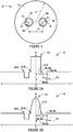
- Figures 2A and 2B depict the relative refractive index percent, ⁇ , vs. radius, r, for a core 20, 30 within the two-core optical fiber 10.
- Cores 20 and 30 can have a simple step index profile (see Figure 2A ) or a graded index profile (see Figure 2B ).
- the low refractive index ring 28,38 can also be placed in the cladding 36 of fiber 10 to increase light confinement in either or both of cores 20 and 30.
- the maximum refractive index of the core 20,30 is greater than the maximum refractive index of the cladding 36.
- the relative refractive index of the core to the cladding, ⁇ 1 is greater than 0.2%. More preferably, the relative refractive index, ⁇ 1 , is greater than 0.3%, for example, between 0.3% to 2%.
- the core radius 24 and 34 are selected in the range of 3 to 10 ⁇ m. This ensures that core 20 and 30 are in a single mode at an operating wavelength, for example 1550 nm.
- the low refractive index ring 28, 38 has a relative refractive index, ⁇ 2 , in the range of -0.7% to -0.1%, and a width 28 w , 38 w in the range of 1 to 6 ⁇ m.
- This low index "trench" can be offset by a distance 28d, 38d from the outer diameter of core 20 and/or 30.
- the offset 28 d , 38 d is between 0 to 5 ⁇ m.
- the distance 16 between the two cores 20 and 30 is greater than 25 ⁇ m to minimize the crosstalk between them. More preferably, distance 16 is greater than 30 ⁇ m. Even more preferably, distance 16 exceeds 40 ⁇ m.
- the diameter of fiber 10 may be 1000 ⁇ m or less (i.e., radius 14 is 500 ⁇ m or less). Preferably, the diameter of fiber 10 is 200 ⁇ m or less (i.e., radius 14 is 100 ⁇ m or less). More preferably, the diameter of fiber 10 is 150 ⁇ m or less. For example, the diameter of fiber 10 maybe set at 125 ⁇ m.
- the crosstalk may be -20 dB/km or less.
- the crosstalk is less than -30 dB/km. More preferably, the amount of crosstalk is less than -35 dB/km. Even more preferably, the crosstalk is less than -40 dB/km.
- a two-core fiber 10 can be designed by calculating the optical and acoustic properties of the two cores 20 and 30.
- f o (r) is the optical field distribution
- n o (r) describes the refractive index as a function of the radial position
- k o is the optical wave number, which is linked to the optical wavelength ⁇ by 2 ⁇ / ⁇ .
- f a (r) is the acoustic field distribution
- n a (r) describes the refractive index as a function of radial position
- k a is the acoustic wave number.
- n oeff and n aeff are the effective optical refractive index and effective longitudinal acoustic refractive index, respectively.
- V clad is the longitudinal acoustic velocity in the cladding
- V L ( r ) describes the longitudinal acoustic velocity as a function of radial position r .
- n aeff V clad / V eff
- the (optical) refractive index profile, n o ( r ) is often described by the optical delta profile (optical refractive index delta profile), ⁇ o .
- the delta (relative refractive index) for the acoustic refractive index, ⁇ a it is possible to define the delta (relative refractive index) for the acoustic refractive index, ⁇ a , such that each optical refractive index profile, n o ( r ), is also associated with a corresponding acoustic delta profile, n a ( r ) , that describes the acoustic behavior of the longitudinal acoustic field.
- the GeO 2 dopant contributes to an increase in the refractive index from that of pure silica, and the F dopant contributes to a decrease in the refractive index from that of the pure silica.
- Equations (11) and (12) demonstrate that the Ge dopant increases both the optical and acoustic refractive index in the cores 20 and 30 of fiber 10.
- cores 20 and 30 may be doped with 1 to 10 mol% GeO 2 to produce this effect.
- the F dopant decreases the optical index, while increasing the acoustic index.
- Example 1 has two cores, each with a step index (see, e.g., Figure 2A ), and a core spacing of 50 ⁇ m.
- the two cores (cores 1 and 2) are doped with 3.41 and 4.6 mol% GeO 2 , respectively. Both cores are single mode at 1550 nm.
- the mode-field diameters (MFDs) for cores 1 and 2 are 10.3 and 9.2 ⁇ m, respectively.
- the difference in Brillouin frequency shift for these cores is 72.5 Mhz.
- core 1 is the same as core 1 from Example 1.
- the core 2 in Example 2 has a higher GeO 2 doping level of 5.5 mol%.
- the difference in Brillouin frequency shift between these cores is 111.8 Mhz, larger than that estimated in Example 1. Because of larger core delta differences (i.e., differences in relative refractive index) between the cores in Example 2, the cores can be placed closer together.
- the two-core fibers simulated in Examples 3 and 4 have graded index profiles (see, e.g., Figure 2B ). With a graded index design, the MFD is larger for the same core delta levels. However, the Brillouin frequency shift is also smaller for these two-core fiber designs.
- the two-core fiber outlined in Example 5 in Table One possesses cores with step index profiles comparable to the cores in the fiber exhibited by Example 1.
- the two-core fiber of Example 5 also has a low index ring 28, 38 in the cladding encapsulating the cores. This low index ring improves the light confinement, thereby reducing the bending loss. Further, it allows the cores to be placed closer together in the fiber. In Example 5, the core spacing is reduced to 40 ⁇ m.
- the difference in Brillouin frequency shift between the cores is at least 30 Mhz.
- System 100a includes a two-core fiber 110 having two cores, 120 and 130, and a laser 116 (e.g., a pump light laser).
- Laser 116 launches pump light into beam splitter 114, thus splitting the incident light into two beams.
- the two split beams are then directed through a mirror 112 (e.g., a one-way mirror) into one end of fiber 110 and, more specifically, into cores 120 and 130.
- a mirror 112 e.g., a one-way mirror
- Brillouin scattering light from within cores 120 and 130 impinges on the mirror 112 in the reverse direction from the incident light and is then detected by photodetector element 118 (or a pair of photodetector elements 118, associated with cores 120 and 130).
- the photodetector element 118 conducts signal processing on the Brillouin scattered beam, and analyzes it to determine the Brillouin frequency shift associated with cores 120 and 130.
- Figure 3B depicts a BOTDR fiber sensor system 100b, which operates in a fashion similar to the system 100a depicted in Figure 3A .
- pump light from laser 116 is launched through a mirror 112 (e.g., a one-way mirror) into core 120 from one end of the fiber 110.
- Cores 120 and 130 are coupled together at the other end of fiber 110 by virtue of another mirror, mirror 112a.
- Mirror 112a alternatively, may be replaced by other types of known external loop devices.
- the light from laser 116 travels through core 120, and then loops through core 130.
- Brillouin scattering light from within both cores 120 and 130 travels back through core 120, impinges on mirror 112, and is then detected by photodetector element 118. Note that light traveling through core 130 does not impinge on mirror 112. The photodetector element 118 then conducts signal processing on the Brillouin scattered beam, and analyzes it to determine the Brillouin frequency shift associated with cores 120 and 130.
- a BOTDA fiber sensor system 200a is depicted schematically in Figure 4A .
- probe light from laser 116a is launched into both fiber cores 120 and 130 from one end of fiber 110 through a mirror 112 (e.g., a one-way mirror).
- pump light from laser 116b is launched into both fiber cores 120 and 130 from the other end of fiber 110.
- the light from lasers 116a and 116b is split into two beams corresponding to cores 120 and 130 with the beam splitter elements 114. These split beams are then directed into cores 120 and 130 from both ends of fiber 110.
- the transmitted light within cores 120 and 130 is then reflected against mirror 112 and photodetector element 118 (or a pair of photodetector elements 118 corresponding to cores 120 and 130) is used to detect the beams.
- Photodetector element 118 then analyzes the data to determine the Brillouin frequency shift associated with cores 120 and 130.
- Probe light from lasers 116a and 116b is launched through a mirror 112 (e.g., a one-way mirror) into both fiber cores 120 and 130, respectively, from one end of fiber 110. More specifically, probe light transmitted through the core 120 from laser 116a emanates from the other end of fiber 110 and is reflected back through core 130 by virtue of mirror element 112a. Similarly, pump light transmitted through the core 130 from laser 116b emanates from the other end of fiber 110 and is reflected back through core 120.
- a mirror 112 e.g., a one-way mirror
- Transmitted light within cores 120 and 130 travels back through core 120, is then reflected against mirror 112 and, as with configurations 100a, 100b and 200a, photodetector element 118 is used to detect the reflected beam. Again, note that light traveling through core 130 does not impinge on mirror 112. Photodetector element 118 then analyzes the data to determine the Brillouin frequency shift associated with cores 120 and 130.
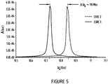
- a two-core fiber 10 has been manufactured with two cores, each with a measured radius of 4.65 ⁇ m and a fiber diameter of 125 ⁇ m. Both cores have a step-shaped refractive index profile (see, e.g., Figure 2A ), and a measured core spacing of 55.5 ⁇ m.
- the two cores 1 and 2 are doped with 5.0 and 3.4 mol% GeO 2 , respectively.
- the MFDs calculated for these cores are 9.3 and 10.4 ⁇ m, respectively. Brillouin frequency shift values of 10.73 and 10.85 Ghz were measured for cores 1 and 2, respectively.
- Figure 5 depicts a Brillouin spectrum for each core of the fiber 10 (as outlined in Table Two), demonstrating the origin of these frequency shift values. Accordingly, the measured change in BFS, ⁇ v B , for this two-core fiber is 118 Mhz (see also Figure 5 ). Furthermore, the 118 Mhz measured change in BFS, ⁇ v B , is comparable to the 111.8 and 111.9 Mhz calculated values for the similarly-structured Example 2 and Example 5 fibers, respectively.
- the two-core fiber approach can thus be used to improve the accuracy of simultaneous strain and temperature measurements in both BOTDA and BOTDR regimes.
- the two-core fiber approach is expected to reduce the installation cost of distributed Brillouin fiber sensors.
Landscapes
- Physics & Mathematics (AREA)
- General Physics & Mathematics (AREA)
- Optics & Photonics (AREA)
- Health & Medical Sciences (AREA)
- Analytical Chemistry (AREA)
- Nuclear Medicine, Radiotherapy & Molecular Imaging (AREA)
- Life Sciences & Earth Sciences (AREA)
- Chemical & Material Sciences (AREA)
- Nonlinear Science (AREA)
- Biochemistry (AREA)
- General Health & Medical Sciences (AREA)
- Immunology (AREA)
- Pathology (AREA)
- Spectroscopy & Molecular Physics (AREA)
- Optical Transform (AREA)
- Testing Or Calibration Of Command Recording Devices (AREA)
Applications Claiming Priority (3)
| Application Number | Priority Date | Filing Date | Title |
|---|---|---|---|
| US201261681402P | 2012-08-09 | 2012-08-09 | |
| US13/658,991 US9574911B2 (en) | 2012-08-09 | 2012-10-24 | Two-core optical fibers for distributed fiber sensors and systems |
| PCT/US2013/053228 WO2014025614A1 (en) | 2012-08-09 | 2013-08-01 | Two-core optical fibers for distributed fiber sensors and systems |
Publications (2)
| Publication Number | Publication Date |
|---|---|
| EP2883023A1 EP2883023A1 (en) | 2015-06-17 |
| EP2883023B1 true EP2883023B1 (en) | 2019-10-02 |
Family
ID=50065476
Family Applications (1)
| Application Number | Title | Priority Date | Filing Date |
|---|---|---|---|
| EP13745994.7A Active EP2883023B1 (en) | 2012-08-09 | 2013-08-01 | Two-core optical fibers for distributed fiber sensors and systems |
Country Status (5)
| Country | Link |
|---|---|
| US (2) | US9574911B2 (enExample) |
| EP (1) | EP2883023B1 (enExample) |
| JP (2) | JP2015531861A (enExample) |
| CA (1) | CA2920157C (enExample) |
| WO (1) | WO2014025614A1 (enExample) |
Families Citing this family (31)
| Publication number | Priority date | Publication date | Assignee | Title |
|---|---|---|---|---|
| US9651435B2 (en) * | 2013-03-19 | 2017-05-16 | Halliburton Energy Services, Inc. | Distributed strain and temperature sensing system |
| US9470841B2 (en) * | 2013-12-06 | 2016-10-18 | Cornning Incorporated | Multicore optical fiber with multimode cores |
| CA2851047C (en) | 2014-05-06 | 2022-10-18 | Oz Optics Ltd. | Method and system for simultaneous measurement of strain and temperature utilizing dual core fiber |
| JP2016020865A (ja) * | 2014-07-15 | 2016-02-04 | 古河電気工業株式会社 | 光ファイバを用いた応力分布測定方法および応力分布測定装置 |
| US9599460B2 (en) | 2014-10-16 | 2017-03-21 | Nec Corporation | Hybrid Raman and Brillouin scattering in few-mode fibers |
| US9784567B2 (en) | 2014-10-16 | 2017-10-10 | Nec Corporation | Distributed brillouin sensing using correlation |
| US10422631B2 (en) | 2014-11-11 | 2019-09-24 | Luna Innovations Incorporated | Optical fiber and method and apparatus for accurate fiber optic sensing under multiple stimuli |
| JP6346852B2 (ja) * | 2014-11-27 | 2018-06-20 | 日本電信電話株式会社 | 光ファイバの曲げ形状測定装置及びその曲げ形状測定方法 |
| JP6283602B2 (ja) * | 2014-11-27 | 2018-02-21 | 日本電信電話株式会社 | 光ファイバの曲げ形状測定装置及びその曲げ形状測定方法 |
| JP6346851B2 (ja) * | 2014-11-27 | 2018-06-20 | 日本電信電話株式会社 | 光ファイバの曲げ形状測定装置及びその曲げ形状測定方法 |
| CN107003473B (zh) | 2014-12-15 | 2020-09-11 | 直观外科手术操作公司 | 用于应变和温度分离的多芯光纤中的不同的纤芯 |
| FR3047076A1 (fr) * | 2016-01-26 | 2017-07-28 | Commissariat Energie Atomique | Dispositif distribue de detection d'une substance |
| CN105741475B (zh) * | 2016-05-11 | 2023-08-01 | 广州天赋人财光电科技有限公司 | 冗余分布式光纤线型感温火灾探测方法及系统 |
| CN106482792A (zh) * | 2016-11-21 | 2017-03-08 | 深圳市道桥维修中心桥梁检测站 | 基于布里渊分布式光纤传感技术的桥梁健康监测系统 |
| JP6360929B1 (ja) | 2017-02-15 | 2018-07-18 | 株式会社フジクラ | 光ファイバセンサ |
| CN110068556A (zh) * | 2018-01-23 | 2019-07-30 | 桂林电子科技大学 | 用于光谱测量的光纤微流芯片 |
| CN110112636B (zh) * | 2018-02-01 | 2020-10-16 | 桂林电子科技大学 | 基于双芯光纤产生两倍布里渊频率微波信号的装置 |
| CN110113104B (zh) * | 2018-02-01 | 2021-07-02 | 桂林电子科技大学 | 一种基于单模双芯光纤产生可调微波信号的装置 |
| EP3627112A1 (en) | 2018-09-20 | 2020-03-25 | Koninklijke Philips N.V. | Optical fiber sensor |
| CN109000157B (zh) * | 2018-10-01 | 2024-03-29 | 江苏亨通光纤科技有限公司 | 一种管道在线监测装置和监测方法 |
| WO2021040687A1 (en) * | 2019-08-26 | 2021-03-04 | Corning Incorporated | Multicore fiber crosstalk sensor with matched effective index |
| CN110987226A (zh) * | 2019-11-26 | 2020-04-10 | 国网河南省电力公司检修公司 | 基于分布式光纤传感的干式电抗器过热故障预警系统 |
| JP2023518941A (ja) | 2020-03-18 | 2023-05-09 | コーニング インコーポレイテッド | マイクロベンドが改善された直径の減少した光ファイバ |
| NL2025271B1 (en) * | 2020-03-18 | 2021-10-20 | Corning Inc | Reduced diameter optical fiber with improved microbending |
| WO2021188290A1 (en) * | 2020-03-19 | 2021-09-23 | Corning Incorporated | Multicore fiber with exterior cladding region |
| CN111487000B (zh) * | 2020-04-21 | 2021-10-15 | 东北大学 | 一种基于微纳多芯特种光纤的矢量应力计 |
| CN111510205B (zh) * | 2020-04-21 | 2022-07-12 | 北京邮电大学 | 一种基于深度学习的光缆故障定位方法、装置及设备 |
| JP7722383B2 (ja) * | 2020-09-24 | 2025-08-13 | 住友電気工業株式会社 | マルチコア光ファイバ及び光伝送システム |
| CN113819931B (zh) * | 2021-09-28 | 2023-06-16 | 北京卫星环境工程研究所 | 一种botdr和botda融合使用的布里渊频移的提取方法 |
| CN114061826B (zh) * | 2021-11-17 | 2024-07-26 | 海南赛沐科技有限公司 | 一种全海深海水压力分布监测方法和装置 |
| WO2023172459A1 (en) * | 2022-03-07 | 2023-09-14 | Ofs Fitel, Llc | Systems, methods and assemblies for single input shape sensing |
Citations (1)
| Publication number | Priority date | Publication date | Assignee | Title |
|---|---|---|---|---|
| US20080084914A1 (en) * | 2005-09-29 | 2008-04-10 | Yoshinori Yamamoto | Sensor and Disturbance Measurement Method Using the Same |
Family Cites Families (26)
| Publication number | Priority date | Publication date | Assignee | Title |
|---|---|---|---|---|
| US3231205A (en) * | 1963-08-01 | 1966-01-25 | Iowa Mfg Company | Crushing rolls |
| US5696863A (en) | 1982-08-06 | 1997-12-09 | Kleinerman; Marcos Y. | Distributed fiber optic temperature sensors and systems |
| JPH0658444B2 (ja) * | 1985-12-03 | 1994-08-03 | 日本電信電話株式会社 | フアイバ形光波長フイルタ |
| US4822126A (en) * | 1987-05-21 | 1989-04-18 | Amphenol Corporation | Wavelength independent coupler and method of manufacture thereof |
| JP2840682B2 (ja) * | 1989-10-03 | 1998-12-24 | 日本電信電話株式会社 | 光導波路の歪または温度の測定方法および装置 |
| JPH03220504A (ja) * | 1990-01-26 | 1991-09-27 | Sumitomo Electric Ind Ltd | 光ファイバ応力付与型センサ |
| JPH03231205A (ja) * | 1990-02-07 | 1991-10-15 | Sumitomo Electric Ind Ltd | 応力付与型センサ用光ファイバ |
| JPH04134402A (ja) * | 1990-09-27 | 1992-05-08 | Fujikura Ltd | デュアルコアファイバ |
| US5144690A (en) * | 1990-12-03 | 1992-09-01 | Corning Incorporated | Optical fiber sensor with localized sensing regions |
| JPH0658712A (ja) * | 1992-08-11 | 1994-03-04 | Fujikura Ltd | 光ファイバセンサ |
| GB9713018D0 (en) | 1997-06-20 | 1997-08-27 | Secr Defence | Optical fibre bend sensor |
| US6611648B2 (en) | 2001-05-09 | 2003-08-26 | Corning Incorporated | Optical fibers having cores with different propagation constants, and methods of manufacturing same |
| GB0524838D0 (en) | 2005-12-06 | 2006-01-11 | Sensornet Ltd | Sensing system using optical fiber suited to high temperatures |
| JP4865423B2 (ja) * | 2006-07-03 | 2012-02-01 | 日本電信電話株式会社 | 光ファイバセンサおよびそれを用いた歪み測定方法 |
| US7599047B2 (en) * | 2006-10-20 | 2009-10-06 | Oz Optics Ltd. | Method and system for simultaneous measurement of strain and temperature |
| JP4759493B2 (ja) * | 2006-11-08 | 2011-08-31 | 日本電信電話株式会社 | 光設備検出方法および光設備検出システム |
| JP5000443B2 (ja) * | 2007-09-26 | 2012-08-15 | 日本電信電話株式会社 | 光ファイバの後方ブリルアン散乱光測定方法及び装置 |
| JP5222514B2 (ja) * | 2007-09-26 | 2013-06-26 | 日本電信電話株式会社 | 光ファイバ測定方法、光ファイバ測定システムおよび光ファイバ測定装置 |
| JP2009098020A (ja) * | 2007-10-17 | 2009-05-07 | Fujikura Ltd | 分布型光ファイバ温度センサ |
| US8123400B2 (en) * | 2008-04-16 | 2012-02-28 | Ofs Fitel, Llc | Multi-core fiber grating sensor |
| CA2629446C (en) | 2008-04-18 | 2015-09-08 | Oz Optics Ltd. | Method and system for simultaneous measurement of strain and temperature |
| EP2110651B1 (en) | 2008-04-18 | 2017-06-07 | OZ Optics Ltd. | Method and system for simultaneous measurement of strain and temperature |
| JP5065187B2 (ja) * | 2008-07-08 | 2012-10-31 | 古河電気工業株式会社 | 光ファイバセンサ |
| EP2388629A4 (en) | 2009-01-19 | 2014-09-03 | Sumitomo Electric Industries | MULTI-CORE FIBER |
| US8488130B2 (en) * | 2009-11-13 | 2013-07-16 | Intuitive Surgical Operations, Inc. | Method and system to sense relative partial-pose information using a shape sensor |
| US8614795B2 (en) * | 2011-07-21 | 2013-12-24 | Baker Hughes Incorporated | System and method of distributed fiber optic sensing including integrated reference path |
-
2012
- 2012-10-24 US US13/658,991 patent/US9574911B2/en not_active Expired - Fee Related
-
2013
- 2013-08-01 WO PCT/US2013/053228 patent/WO2014025614A1/en not_active Ceased
- 2013-08-01 EP EP13745994.7A patent/EP2883023B1/en active Active
- 2013-08-01 JP JP2015526585A patent/JP2015531861A/ja active Pending
- 2013-08-01 CA CA2920157A patent/CA2920157C/en not_active Expired - Fee Related
-
2016
- 2016-12-12 US US15/375,497 patent/US10591666B2/en not_active Expired - Fee Related
-
2019
- 2019-04-26 JP JP2019085147A patent/JP2019144266A/ja not_active Ceased
Patent Citations (1)
| Publication number | Priority date | Publication date | Assignee | Title |
|---|---|---|---|---|
| US20080084914A1 (en) * | 2005-09-29 | 2008-04-10 | Yoshinori Yamamoto | Sensor and Disturbance Measurement Method Using the Same |
Also Published As
| Publication number | Publication date |
|---|---|
| WO2014025614A1 (en) | 2014-02-13 |
| CA2920157C (en) | 2020-08-18 |
| CA2920157A1 (en) | 2014-02-13 |
| EP2883023A1 (en) | 2015-06-17 |
| US10591666B2 (en) | 2020-03-17 |
| JP2019144266A (ja) | 2019-08-29 |
| US20170089834A1 (en) | 2017-03-30 |
| JP2015531861A (ja) | 2015-11-05 |
| US20140042306A1 (en) | 2014-02-13 |
| US9574911B2 (en) | 2017-02-21 |
Similar Documents
| Publication | Publication Date | Title |
|---|---|---|
| EP2883023B1 (en) | Two-core optical fibers for distributed fiber sensors and systems | |
| US8744782B2 (en) | System and method for simultaneously determining strain and temperature characteristics of an object | |
| US11243122B2 (en) | Methods and systems using optical fiber interferometry | |
| EP2702353B1 (en) | Distributed brillouin sensing systems and methods using few-mode sensing optical fiber | |
| EP2817593B1 (en) | Sensing systems and few-mode optical fiber for use in such systems | |
| EP2457062B1 (en) | Distributed optical fibre sensing | |
| EP2110652B1 (en) | Multi-core fiber grating sensor | |
| CN105865752B (zh) | 采用分布式偏振串扰分析仪全面评判保偏光纤特性的方法和装置 | |
| EP3488191B1 (en) | Brillouin-based distributed bend fiber sensor and method for using same | |
| EP2977738B1 (en) | Systems and methods for distributed pressure sensing | |
| US10724922B1 (en) | Complete characterization of polarization-maintaining fibers using distributed polarization analysis | |
| Dong et al. | Simultaneous temperature and strain sensing based on M-shaped single mode fiber | |
| Bogachkov | Temperature dependences of Mandelstam-Brillouin backscatter spectrum in optical fibers of various types | |
| CN105865655B (zh) | 一种基于光纤声光模互作用的温度和应变同时测量方法 | |
| Delepine-Lesoille et al. | Validation of TW-COTDR method for 25km distributed optical fiber sensing | |
| EP2805139B1 (en) | Temperature and strain sensing optical fiber and temperature and strain sensor | |
| Li et al. | Dual core optical fiber for distributed Brillouin fiber sensors | |
| Kaur et al. | Experiment on a highly sensitive fiber Bragg grating optical sensor to monitor strain and corrosion in civil structures | |
| US20120175512A1 (en) | Rayleigh scatter-based large diameter waveguide sensor system | |
| Li et al. | Novel optical fibers for distributed sensor applications | |
| US9546886B2 (en) | Distributed environmental fiber optic sensor and system | |
| Lebang et al. | Detection of displacement using glass optical fiber sensor with various configuration | |
| Wosniok et al. | Simultaneous measurement of temperature and strain distribution using Brillouin scattering in dispersion-shifted fibers | |
| Lebang et al. | Indonesian Physical Review | |
| Wosniok | Brillouin gain spectrum characteristics for temperature compensation in fiber optic distributed strain sensor |
Legal Events
| Date | Code | Title | Description |
|---|---|---|---|
| PUAI | Public reference made under article 153(3) epc to a published international application that has entered the european phase |
Free format text: ORIGINAL CODE: 0009012 |
|
| 17P | Request for examination filed |
Effective date: 20150226 |
|
| AK | Designated contracting states |
Kind code of ref document: A1 Designated state(s): AL AT BE BG CH CY CZ DE DK EE ES FI FR GB GR HR HU IE IS IT LI LT LU LV MC MK MT NL NO PL PT RO RS SE SI SK SM TR |
|
| AX | Request for extension of the european patent |
Extension state: BA ME |
|
| DAX | Request for extension of the european patent (deleted) | ||
| STAA | Information on the status of an ep patent application or granted ep patent |
Free format text: STATUS: EXAMINATION IS IN PROGRESS |
|
| 17Q | First examination report despatched |
Effective date: 20180213 |
|
| GRAP | Despatch of communication of intention to grant a patent |
Free format text: ORIGINAL CODE: EPIDOSNIGR1 |
|
| STAA | Information on the status of an ep patent application or granted ep patent |
Free format text: STATUS: GRANT OF PATENT IS INTENDED |
|
| INTG | Intention to grant announced |
Effective date: 20190416 |
|
| GRAS | Grant fee paid |
Free format text: ORIGINAL CODE: EPIDOSNIGR3 |
|
| GRAA | (expected) grant |
Free format text: ORIGINAL CODE: 0009210 |
|
| STAA | Information on the status of an ep patent application or granted ep patent |
Free format text: STATUS: THE PATENT HAS BEEN GRANTED |
|
| AK | Designated contracting states |
Kind code of ref document: B1 Designated state(s): AL AT BE BG CH CY CZ DE DK EE ES FI FR GB GR HR HU IE IS IT LI LT LU LV MC MK MT NL NO PL PT RO RS SE SI SK SM TR |
|
| REG | Reference to a national code |
Ref country code: GB Ref legal event code: FG4D |
|
| REG | Reference to a national code |
Ref country code: CH Ref legal event code: EP Ref country code: AT Ref legal event code: REF Ref document number: 1186704 Country of ref document: AT Kind code of ref document: T Effective date: 20191015 |
|
| REG | Reference to a national code |
Ref country code: DE Ref legal event code: R096 Ref document number: 602013061228 Country of ref document: DE |
|
| REG | Reference to a national code |
Ref country code: IE Ref legal event code: FG4D |
|
| REG | Reference to a national code |
Ref country code: NL Ref legal event code: MP Effective date: 20191002 |
|
| REG | Reference to a national code |
Ref country code: LT Ref legal event code: MG4D |
|
| REG | Reference to a national code |
Ref country code: AT Ref legal event code: MK05 Ref document number: 1186704 Country of ref document: AT Kind code of ref document: T Effective date: 20191002 |
|
| PG25 | Lapsed in a contracting state [announced via postgrant information from national office to epo] |
Ref country code: GR Free format text: LAPSE BECAUSE OF FAILURE TO SUBMIT A TRANSLATION OF THE DESCRIPTION OR TO PAY THE FEE WITHIN THE PRESCRIBED TIME-LIMIT Effective date: 20200103 Ref country code: ES Free format text: LAPSE BECAUSE OF FAILURE TO SUBMIT A TRANSLATION OF THE DESCRIPTION OR TO PAY THE FEE WITHIN THE PRESCRIBED TIME-LIMIT Effective date: 20191002 Ref country code: LT Free format text: LAPSE BECAUSE OF FAILURE TO SUBMIT A TRANSLATION OF THE DESCRIPTION OR TO PAY THE FEE WITHIN THE PRESCRIBED TIME-LIMIT Effective date: 20191002 Ref country code: NL Free format text: LAPSE BECAUSE OF FAILURE TO SUBMIT A TRANSLATION OF THE DESCRIPTION OR TO PAY THE FEE WITHIN THE PRESCRIBED TIME-LIMIT Effective date: 20191002 Ref country code: AT Free format text: LAPSE BECAUSE OF FAILURE TO SUBMIT A TRANSLATION OF THE DESCRIPTION OR TO PAY THE FEE WITHIN THE PRESCRIBED TIME-LIMIT Effective date: 20191002 Ref country code: SE Free format text: LAPSE BECAUSE OF FAILURE TO SUBMIT A TRANSLATION OF THE DESCRIPTION OR TO PAY THE FEE WITHIN THE PRESCRIBED TIME-LIMIT Effective date: 20191002 Ref country code: LV Free format text: LAPSE BECAUSE OF FAILURE TO SUBMIT A TRANSLATION OF THE DESCRIPTION OR TO PAY THE FEE WITHIN THE PRESCRIBED TIME-LIMIT Effective date: 20191002 Ref country code: PL Free format text: LAPSE BECAUSE OF FAILURE TO SUBMIT A TRANSLATION OF THE DESCRIPTION OR TO PAY THE FEE WITHIN THE PRESCRIBED TIME-LIMIT Effective date: 20191002 Ref country code: NO Free format text: LAPSE BECAUSE OF FAILURE TO SUBMIT A TRANSLATION OF THE DESCRIPTION OR TO PAY THE FEE WITHIN THE PRESCRIBED TIME-LIMIT Effective date: 20200102 Ref country code: FI Free format text: LAPSE BECAUSE OF FAILURE TO SUBMIT A TRANSLATION OF THE DESCRIPTION OR TO PAY THE FEE WITHIN THE PRESCRIBED TIME-LIMIT Effective date: 20191002 Ref country code: PT Free format text: LAPSE BECAUSE OF FAILURE TO SUBMIT A TRANSLATION OF THE DESCRIPTION OR TO PAY THE FEE WITHIN THE PRESCRIBED TIME-LIMIT Effective date: 20200203 Ref country code: BG Free format text: LAPSE BECAUSE OF FAILURE TO SUBMIT A TRANSLATION OF THE DESCRIPTION OR TO PAY THE FEE WITHIN THE PRESCRIBED TIME-LIMIT Effective date: 20200102 |
|
| PG25 | Lapsed in a contracting state [announced via postgrant information from national office to epo] |
Ref country code: CZ Free format text: LAPSE BECAUSE OF FAILURE TO SUBMIT A TRANSLATION OF THE DESCRIPTION OR TO PAY THE FEE WITHIN THE PRESCRIBED TIME-LIMIT Effective date: 20191002 Ref country code: RS Free format text: LAPSE BECAUSE OF FAILURE TO SUBMIT A TRANSLATION OF THE DESCRIPTION OR TO PAY THE FEE WITHIN THE PRESCRIBED TIME-LIMIT Effective date: 20191002 Ref country code: HR Free format text: LAPSE BECAUSE OF FAILURE TO SUBMIT A TRANSLATION OF THE DESCRIPTION OR TO PAY THE FEE WITHIN THE PRESCRIBED TIME-LIMIT Effective date: 20191002 Ref country code: IS Free format text: LAPSE BECAUSE OF FAILURE TO SUBMIT A TRANSLATION OF THE DESCRIPTION OR TO PAY THE FEE WITHIN THE PRESCRIBED TIME-LIMIT Effective date: 20200224 |
|
| PG25 | Lapsed in a contracting state [announced via postgrant information from national office to epo] |
Ref country code: AL Free format text: LAPSE BECAUSE OF FAILURE TO SUBMIT A TRANSLATION OF THE DESCRIPTION OR TO PAY THE FEE WITHIN THE PRESCRIBED TIME-LIMIT Effective date: 20191002 |
|
| REG | Reference to a national code |
Ref country code: DE Ref legal event code: R097 Ref document number: 602013061228 Country of ref document: DE |
|
| PG2D | Information on lapse in contracting state deleted |
Ref country code: IS |
|
| PG25 | Lapsed in a contracting state [announced via postgrant information from national office to epo] |
Ref country code: EE Free format text: LAPSE BECAUSE OF FAILURE TO SUBMIT A TRANSLATION OF THE DESCRIPTION OR TO PAY THE FEE WITHIN THE PRESCRIBED TIME-LIMIT Effective date: 20191002 Ref country code: DK Free format text: LAPSE BECAUSE OF FAILURE TO SUBMIT A TRANSLATION OF THE DESCRIPTION OR TO PAY THE FEE WITHIN THE PRESCRIBED TIME-LIMIT Effective date: 20191002 Ref country code: RO Free format text: LAPSE BECAUSE OF FAILURE TO SUBMIT A TRANSLATION OF THE DESCRIPTION OR TO PAY THE FEE WITHIN THE PRESCRIBED TIME-LIMIT Effective date: 20191002 Ref country code: IS Free format text: LAPSE BECAUSE OF FAILURE TO SUBMIT A TRANSLATION OF THE DESCRIPTION OR TO PAY THE FEE WITHIN THE PRESCRIBED TIME-LIMIT Effective date: 20200202 |
|
| PLBE | No opposition filed within time limit |
Free format text: ORIGINAL CODE: 0009261 |
|
| STAA | Information on the status of an ep patent application or granted ep patent |
Free format text: STATUS: NO OPPOSITION FILED WITHIN TIME LIMIT |
|
| PG25 | Lapsed in a contracting state [announced via postgrant information from national office to epo] |
Ref country code: SK Free format text: LAPSE BECAUSE OF FAILURE TO SUBMIT A TRANSLATION OF THE DESCRIPTION OR TO PAY THE FEE WITHIN THE PRESCRIBED TIME-LIMIT Effective date: 20191002 Ref country code: IT Free format text: LAPSE BECAUSE OF FAILURE TO SUBMIT A TRANSLATION OF THE DESCRIPTION OR TO PAY THE FEE WITHIN THE PRESCRIBED TIME-LIMIT Effective date: 20191002 Ref country code: SM Free format text: LAPSE BECAUSE OF FAILURE TO SUBMIT A TRANSLATION OF THE DESCRIPTION OR TO PAY THE FEE WITHIN THE PRESCRIBED TIME-LIMIT Effective date: 20191002 |
|
| 26N | No opposition filed |
Effective date: 20200703 |
|
| PGFP | Annual fee paid to national office [announced via postgrant information from national office to epo] |
Ref country code: GB Payment date: 20200729 Year of fee payment: 8 |
|
| PG25 | Lapsed in a contracting state [announced via postgrant information from national office to epo] |
Ref country code: SI Free format text: LAPSE BECAUSE OF FAILURE TO SUBMIT A TRANSLATION OF THE DESCRIPTION OR TO PAY THE FEE WITHIN THE PRESCRIBED TIME-LIMIT Effective date: 20191002 |
|
| REG | Reference to a national code |
Ref country code: DE Ref legal event code: R119 Ref document number: 602013061228 Country of ref document: DE |
|
| PG25 | Lapsed in a contracting state [announced via postgrant information from national office to epo] |
Ref country code: MC Free format text: LAPSE BECAUSE OF FAILURE TO SUBMIT A TRANSLATION OF THE DESCRIPTION OR TO PAY THE FEE WITHIN THE PRESCRIBED TIME-LIMIT Effective date: 20191002 |
|
| REG | Reference to a national code |
Ref country code: CH Ref legal event code: PL |
|
| PG25 | Lapsed in a contracting state [announced via postgrant information from national office to epo] |
Ref country code: LU Free format text: LAPSE BECAUSE OF NON-PAYMENT OF DUE FEES Effective date: 20200801 Ref country code: LI Free format text: LAPSE BECAUSE OF NON-PAYMENT OF DUE FEES Effective date: 20200831 Ref country code: CH Free format text: LAPSE BECAUSE OF NON-PAYMENT OF DUE FEES Effective date: 20200831 |
|
| REG | Reference to a national code |
Ref country code: BE Ref legal event code: MM Effective date: 20200831 |
|
| PG25 | Lapsed in a contracting state [announced via postgrant information from national office to epo] |
Ref country code: FR Free format text: LAPSE BECAUSE OF NON-PAYMENT OF DUE FEES Effective date: 20200831 Ref country code: DE Free format text: LAPSE BECAUSE OF NON-PAYMENT OF DUE FEES Effective date: 20210302 |
|
| PG25 | Lapsed in a contracting state [announced via postgrant information from national office to epo] |
Ref country code: BE Free format text: LAPSE BECAUSE OF NON-PAYMENT OF DUE FEES Effective date: 20200831 Ref country code: IE Free format text: LAPSE BECAUSE OF NON-PAYMENT OF DUE FEES Effective date: 20200801 |
|
| GBPC | Gb: european patent ceased through non-payment of renewal fee |
Effective date: 20210801 |
|
| PG25 | Lapsed in a contracting state [announced via postgrant information from national office to epo] |
Ref country code: TR Free format text: LAPSE BECAUSE OF FAILURE TO SUBMIT A TRANSLATION OF THE DESCRIPTION OR TO PAY THE FEE WITHIN THE PRESCRIBED TIME-LIMIT Effective date: 20191002 Ref country code: MT Free format text: LAPSE BECAUSE OF FAILURE TO SUBMIT A TRANSLATION OF THE DESCRIPTION OR TO PAY THE FEE WITHIN THE PRESCRIBED TIME-LIMIT Effective date: 20191002 Ref country code: CY Free format text: LAPSE BECAUSE OF FAILURE TO SUBMIT A TRANSLATION OF THE DESCRIPTION OR TO PAY THE FEE WITHIN THE PRESCRIBED TIME-LIMIT Effective date: 20191002 |
|
| PG25 | Lapsed in a contracting state [announced via postgrant information from national office to epo] |
Ref country code: MK Free format text: LAPSE BECAUSE OF FAILURE TO SUBMIT A TRANSLATION OF THE DESCRIPTION OR TO PAY THE FEE WITHIN THE PRESCRIBED TIME-LIMIT Effective date: 20191002 |
|
| PG25 | Lapsed in a contracting state [announced via postgrant information from national office to epo] |
Ref country code: GB Free format text: LAPSE BECAUSE OF NON-PAYMENT OF DUE FEES Effective date: 20210801 |