EP2882172A1 - Mobiltelefonhalteeinrichtung - Google Patents
Mobiltelefonhalteeinrichtung Download PDFInfo
- Publication number
- EP2882172A1 EP2882172A1 EP14190574.5A EP14190574A EP2882172A1 EP 2882172 A1 EP2882172 A1 EP 2882172A1 EP 14190574 A EP14190574 A EP 14190574A EP 2882172 A1 EP2882172 A1 EP 2882172A1
- Authority
- EP
- European Patent Office
- Prior art keywords
- rod
- mobile telephone
- holding device
- hollow body
- clamping
- Prior art date
- Legal status (The legal status is an assumption and is not a legal conclusion. Google has not performed a legal analysis and makes no representation as to the accuracy of the status listed.)
- Granted
Links
- 238000003780 insertion Methods 0.000 claims description 6
- 230000037431 insertion Effects 0.000 claims description 6
- 230000001360 synchronised effect Effects 0.000 claims 4
- 230000005489 elastic deformation Effects 0.000 claims 1
- 238000006073 displacement reaction Methods 0.000 description 2
- 240000001439 Opuntia Species 0.000 description 1
- 235000004727 Opuntia ficus indica Nutrition 0.000 description 1
- 230000004308 accommodation Effects 0.000 description 1
- 230000001419 dependent effect Effects 0.000 description 1
- 238000011161 development Methods 0.000 description 1
- 230000018109 developmental process Effects 0.000 description 1
- 239000012780 transparent material Substances 0.000 description 1
Images



Classifications
-
- H—ELECTRICITY
- H04—ELECTRIC COMMUNICATION TECHNIQUE
- H04M—TELEPHONIC COMMUNICATION
- H04M1/00—Substation equipment, e.g. for use by subscribers
- H04M1/02—Constructional features of telephone sets
- H04M1/04—Supports for telephone transmitters or receivers
-
- H—ELECTRICITY
- H04—ELECTRIC COMMUNICATION TECHNIQUE
- H04B—TRANSMISSION
- H04B1/00—Details of transmission systems, not covered by a single one of groups H04B3/00 - H04B13/00; Details of transmission systems not characterised by the medium used for transmission
- H04B1/38—Transceivers, i.e. devices in which transmitter and receiver form a structural unit and in which at least one part is used for functions of transmitting and receiving
- H04B1/3827—Portable transceivers
- H04B1/3877—Arrangements for enabling portable transceivers to be used in a fixed position, e.g. cradles or boosters
Definitions
- the invention relates to a mobile telephone holding device according to the preamble of claim 1.
- a mobile telephone holding device which comprises a hollow body with a receiving space and a bottom and a clamping device, wherein a mobile phone can be placed on the floor and wherein the hollow body comprises at least two opposite walls and on an opposite side of the bottom comprises an opening.
- a disadvantage of such a mobile phone holder device is that it can only be used for mobile phones of a certain design, so that the mobile phone holder device has to be exchanged for the use of another type of mobile phone in the design at least partially.
- a further object of the invention is to cover the display of a mobile phone received in the holder by the holder as little as possible or to obtain the readability of the display of the mobile phone as far as possible.
- the inventive mobile phone holder comprises further comprising a rod, wherein the rod extends from the first wall to the second wall of the hollow body, wherein the rod is mounted or formed such that it from a release position, in which the rod and the bottom at a first distance from each other, in a clamping position, in which the rod and the bottom have a second distance from each other, and vice versa, wherein the first distance is greater than the second distance.
- the mobile phone holder is thus suitable for any trained in the range of these dimensions mobile phone.
- the display Due to the design of the component of the mobile phone holder device, which rests on a display of the smartphone designed as a smartphone, in the form of a bar, the display is only minimally obscured. In this case, it is also provided in particular to form the rod from a transparent or transparent material, such that the display of the mobile phone is also readable in an area which is covered by the rod when the mobile phone is clamped in the mobile phone holder.
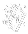
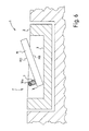
- FIG. 1 a first embodiment of a mobile phone holding device 1 with guide means 8a formed by pivotable arms 9a shown in a sectional partial view.
- the second pivotable arm or the second guide means of a clamping device 4 is not shown, but with respect to a mirror plane SE mirror-symmetrical to the first pivotable arm 9a and the first guide means 9a formed.
- a hollow body 2 comprises a receiving space AR bounded by opposite side walls 2a, 2b, in which a cuboid mobile telephone can be inserted in such a way that it can be placed on a bottom 3 of the mobile telephone holding device 1 with its back surface opposite a display.
- the mobile phone holder device 1 further comprises a rod 7, which is held between the arms 9a of the clamping device 4 and in the FIG.
- the arms 9a In a release position F, the rod 7 to the bottom 3 at a distance D1.
- the distance D1 allows an oblique insertion of the mobile phone in the receiving space.
- the arms 9a can be given away around a rotation axis d9 in the direction of arrow w such that the bar 7 lays on the display, not shown, of the mobile telephone and presses it against the floor 3.
- the mobile phone is secured against displacement between the rod 7 and the bottom 3, wherein the guide means 8a engage in a clamping position K, in which the rod 7 presses the mobile phone on the ground 3.
- This locking of the clamping device 4 can be solved by an unlocking device E, of which only one key is shown again, so that the arms 9a in a reverse direction w 'lift again and the rod 7 is lifted from the display of the mobile phone and back in the in the FIG. 1 shown release position F returns.
- the clamping position K is in the FIG. 1 by a dashed representation of a portion of the rod 7 as a rod 7 ' indicated schematically.
- the rod 7 extends parallel to a transverse axis Q2 of the bottom 3.
- the mobile phone is by a the bottom 3 opposite opening 6 in the receiving space AR and pushed out.
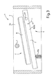
- FIG. 3 the mobile phone holder device 1 in the release position F shows, in which a mobile phone M is inserted into the position shown, without a rod 7, which is disposed between opposite walls 2a of the hollow body 2, the insertion or removal of the mobile phone M obstructed.
- the bottom 3 of the mobile telephone holder 1 is pivotally mounted on arms 9b about an axis of rotation d9, wherein the arms 9b, the guide means 8b of a clamping device 4.
- pressure means 10b act on the bottom 3 in a rotational direction w, wherein the bottom 3 in the release position F by not shown Locking means is held.
- the bottom 3 moves with the lying on it mobile phone M in the direction of rotation w and reaches a in the FIG. 4 shown clamping position K.
- this clamping position K presses the bottom 3, the mobile phone M against the rod 7 so that it is securely held in the mobile phone holder 1.
- the mobile phone holder device 1 can by pressing on a display MD of the mobile phone M back into the in the FIG. 3 shown release position F to be moved, the bottom 3 is held in the release position again with appropriate pressure exerted by the locking means, so that the mobile phone M can be removed.
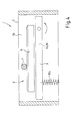
- FIG. 5 An Indian FIG. 5 shown rod 7 is guided in the walls 2a of the hollow body 2 in tracks B1 and is characterized as elastic Body trained pressure means 10 a pressed into a clamping position K.
- FIGS. 6 and 7 is shown as a mobile phone M is inserted into a receiving space AR of the mobile phone holder device 1 and in this case the pressure means 10a is deformed to escape from the clamping position K when inserted into a release position F (see FIG. 6 ) and then push the rod back into the clamping position K, when the mobile phone with its opposite side of the display MD MD rests flat on the floor 3.
- FIG. 8 a fifth variant of the mobile phone holder device 1 is shown, in which a rod 7 is designed as an elastic rod and elastically deformed during insertion of a mobile phone.
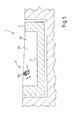
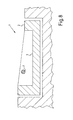
- FIG. 9 a sixth variant of the mobile phone holder device 1 is shown in which a rod 7 is designed as an elastic rod and elastically deformed during insertion of a mobile phone.
- a trough 12 is formed, through which the insertion of the mobile phone between the rod 7 and the bottom 3 is facilitated.
- the mobile phone holder 1 is received in a console KON of a vehicle.
Landscapes
- Engineering & Computer Science (AREA)
- Signal Processing (AREA)
- Computer Networks & Wireless Communication (AREA)
- Telephone Set Structure (AREA)
Abstract
Description
- Die Erfindung betrifft eine Mobiltelefonhaltevorrichtung gemäß dem Oberbegriff des Anspruchs 1.
- Aus der
EP 2 125 434 B1 ist eine Mobiltelefonhaltevorrichtung bekannt, welche als Hohlkörper ein Oberteil mit einem Aufnahmeraum sowie einen Boden und eine Klemmeinrichtung umfasst, wobei ein Mobiltelefon auf dem Boden ablegbar ist und wobei der Hohlkörper wenigstens zwei gegenüberliegende Wände umfasst und an einer dem Boden gegenüberliegenden Seite eine Öffnung umfasst. Nachteilig an einer derartige Mobiltelefonhaltevorrichtung ist, dass diese nur für Mobiltelefone einer bestimmten Bauform verwendbar, so dass die Mobiltelefonhaltevorrichtung zur Nutzung eines in der Bauform anderen Mobiltelefons wenigstens teilweise ausgetauscht werden muss. - Es ist Aufgabe der Erfindung, eine Mobiltelefonhaltevorrichtung vorzuschlagen, welche zur verschiebesicheren Halterung unterschiedlichster Mobiltelefone insbesondere in einem Fahrzeug geeignet ist. Weiterhin ist es Aufgabe der Erfindung das Display eines in der Halterung aufgenommenen Mobiltelefons durch die Halterung möglichst wenig zu überdecken bzw. die Ablesbarkeit des Displays des Mobiltelefons weitestgehend zu erhalten.
- Diese Aufgabe wird ausgehend von den Merkmalen des Oberbegriffs des Anspruchs 1 durch die kennzeichnenden Merkmale des Anspruchs 1 gelöst. In den Unteransprüchen sind vorteilhafte und zweckmäßige Weiterbildungen angegeben.
- Die erfindungsgemäße Mobiltelefonhaltevorrichtung umfasst weiterhin einen Stab umfasst, wobei sich der Stab von der ersten Wand zu der zweiten Wand des Hohlkörpers erstreckt, wobei der Stab derart gelagert oder ausgebildet ist, dass dieser aus einer Freigabestellung, in welcher der Stab und der Boden einen ersten Abstand zueinander aufweisen, in eine Klemmstellung, in welcher der Stab und der Boden einen zweiten Abstand zueinander aufweisen, und umgekehrt verlagerbar ist, wobei der erste Abstand größer als der zweite Abstand ist. Durch eine derartige Anordnung von Stab und Boden in Bezug auf einen zwischen dem Stab und dem Boden ausgebildeten Aufnahmeraum für Mobiltelefone ist es möglich, Mobiltelefone unterschiedlicher Abmessungen in der Freigabestellung in den Aufnahmeraum zu schieben und in der Klemmstellung klemmend zwischen dem Stab und dem Boden zu fixieren. Bei einer an die typischen Mobiltelefonabmessungen angepassten Ausführung des Hohlkörpers, der Freigabestellung des Stabs bzw. des Bodens und der Klemmstellung des Stabs bzw. des Bodens ist die Mobiltelefonhaltevorrichtung somit für jedes im Bereich dieser Abmessungen ausgebildete Mobiltelefon geeignet.
- Durch die Ausbildung des Bauteils der Mobiltelefonhaltervorrichtung, welches auf einem Display des als Smartphone ausgebildeten Mobiltelefons aufliegt, in Form eines Stabes wird das Display nur minimal verdeckt. Hierbei ist es insbesondere auch vorgesehen, den Stab aus einem durchsichtigen oder transparenten Material auszubilden, derart, dass das Display des Mobiltelefons auch in einem Bereich ablesbar ist, welcher durch den Stab verdeckt ist, wenn das Mobiltelefon in der Mobiltelefonhaltevorrichtung geklemmt ist.
- Weitere Einzelheiten der Erfindung werden in der Zeichnung anhand von schematisch dargestellten Ausführungsbeispielen beschreiben.
- Hierbei zeigt:
- Figur 1:
- eine erste Ausführungsvariante einer Mobiltelefonhaltevorrichtung mit durch schwenkbare Arme gebildeten Führungsmitteln in einer geschnittenen Teilansicht;
- Figur 2:
- eine zweite Ausführungsvariante einer Mobiltelefonhaltevorrichtung mit linear durch verfahrbare Arme gebildeten Führungsmitteln;
- Figur 3:
- eine dritte Ausführungsvariante einer Mobiltelefonhaltevorrichtung mit durch schenkbare Arme gebildeten Führungsmitteln in teilweise geschnittener Seitenansicht in einer Freigabestellung;
- Figur 4:
- die dritte Ausführungsvariante in einer Klemmstellung;
- Figur 5:
- eine vierte Ausführungsvariante einer Mobiltelefonhaltevorrichtung mit durch elastische Lager gebildeten Führungsmitteln in teilweise geschnittener Seitenansicht in einer Freigabestellung;
- Figur 6:
- die vierte Ausführungsvariante einer Mobiltelefonhaltevorrichtung bei unvollständig eingelegtem Mobiltelefon;
- Figur 7:
- die vierte Ausführungsvariante einer Mobiltelefonhaltevorrichtung bei vollständig eingelegtem Mobiltelefon;
- Figur 8:
- eine fünfte Ausführungsvariante einer Mobiltelefonhaltevorrichtung mit durch eine elastisch verformbare Stange gebildeten Führungsmitteln in teilweise geschnittener Seitenansicht und
- Figur 9:
- eine sechste Ausführungsvariante einer Mobiltelefonhaltevorrichtung mit einer Mulde und mit durch eine elastisch verformbare Stange gebildeten Führungsmitteln in teilweise geschnittener Seitenansicht.
- In der
Figur 1 eine erste Ausführungsvariante einer Mobiltelefonhaltevorrichtung 1 mit durch schwenkbare Arme 9a gebildeten Führungsmitteln 8a in einer geschnittenen Teilansicht dargestellt. Hierbei ist der zweite schwenkbare Arm bzw. das zweite Führungsmittel einer Klemmeinrichtung 4 nicht dargestellt, aber bezogen auf eine Spiegelebene SE spiegelsymmetrisch zu dem ersten schwenkbaren Arm 9a bzw. dem ersten Führungsmittel 9a ausgebildet. Ein Hohlkörper 2 umfasst einen durch gegenüberliegenden Seitenwände 2a, 2b begrenzten Aufnahmeraum AR, in welchen ein quaderförmiges Mobiltelefon derart einlegbar ist, dass dieses mit seiner einem Display gegenüber liegenden Rückenfläche auf einem Boden 3 der Mobiltelefonhaltevorrichtung 1 ablegbar ist. Die Mobiltelefonhaltevorrichtung 1 umfasst weiterhin einen Stab 7, welcher zwischen den Armen 9a der Klemmeinrichtung 4 gehalten ist und in derFigur 1 von den Armen 9a in einer Freigabestellung F gehalten ist. In dieser Freigabestellung F weist der Stab 7 zu dem Boden 3 einen Abstand D1 auf. Der Abstand D1 ermöglicht ein schräges Einschieben des Mobiltelefons in den Aufnahmeraum. Sobald das Mobiltelefon mit seiner Rückenfläche vollflächig auf dem Boden aufliegt, können die Arme 9a um eine Drehachse d9 in Pfeilrichtung w derart verschenkt werden, dass sich der Stab 7 auf das nicht dargestellte Display des Mobiltelefons legt und dieses gegen den Boden 3 drückt. Hierdurch wird das Mobiltelefon verschiebesicher zwischen dem Stab 7 und dem Boden 3 gehalten, wobei die Führungsmittel 8a in einer Klemmstellung K, in welcher der Stab 7 das Mobiltelefon auf den Boden 3 drückt einrasten. Diese Arretierung der Klemmeinrichtung 4 kann durch eine Entriegelungseinrichtung E, von welcher nur eine Taste dargestellt ist, wieder gelöst werden, so dass sich die Arme 9a in eine Gegendrehrichtung w' wieder anheben und der Stab 7 von dem Display des Mobiltelefons abgehoben wird und wieder in die in derFigur 1 gezeigte Freigabestellung F zurückkehrt. Die Klemmstellung K ist in derFigur 1 durch eine gestrichelte Darstellung eines Abschnitts des Stabs 7 als Stab 7' schematisch angedeutet. Der Stab 7 verläuft parallel zu einer Querachse Q2 des Bodens 3. Das Mobiltelefon ist durch eine dem Boden 3 gegenüberliegende Öffnung 6 in den Aufnahmeraum AR ein- und ausschiebbar. - In der in der
Figur 2 gezeigten zweiten Ausführungsvariante ist ein Stab 7 von den Armen 9a, 9b der Führungsmittel 8a, 8b in vertikaler Richtung linear zwischen einer Freigabestellung und einer nicht dargestellten Klemmstellung verfahrbar. - In den
Figuren 3 und4 ist eine dritte Ausführungsvariante einer Mobiltelefonhaltevorrichtung 1 in geschnittenen Seitenansichten gezeigt, wobei dieFigur 3 die Mobiltelefonhaltevorrichtung 1 in der Freigabestellung F zeigt, in welcher ein Mobiltelefon M in die dargestellte Position einschiebbar ist, ohne dass ein Stab 7, welcher zwischen gegenüberliegenden Wänden 2a des Hohlkörpers 2 angeordnet ist, das Einschieben oder Herausnehmen des Mobiltelefons M behindert. Der Boden 3 der Mobiltelefonhaltevorrichtung 1 ist an Armen 9b schwenkbar um eine Drehachse d9 gelagert, wobei die Arme 9b die Führungsmittel 8b einer Klemmeinrichtung 4. Druckmittel 10b beaufschlagen den Boden 3 in eine Drehrichtung w, wobei der Boden 3 in der Freigabestellung F durch nicht dargestellte Rastmittel gehalten wird. Nach einem Lösen der Rastmittel bewegt sich der Boden 3 mit dem auf ihm liegenden Mobiltelefon M in die Drehrichtung w und erreicht eine in derFigur 4 gezeigte Klemmstellung K. In dieser Klemmstellung K drückt der Boden 3 das Mobiltelefon M gegen den Stab 7, so dass dieses in der Mobiltelefonhaltevorrichtung 1 sicher gehalten ist. Die Mobiltelefonhaltevorrichtung 1 kann durch eine Druckausübung auf ein Display MD des Mobiltelefons M wieder in die in derFigur 3 gezeigte Freigabestellung F bewegt werden, wobei der Boden 3 bei entsprechender Druckausübung durch die Rastmittel wieder in der Freigabestellung gehalten wird, so dass das Mobiltelefon M entnommen werden kann. - Ein in der
Figur 5 gezeigter Stab 7 ist in den Wänden 2a des Hohlkörpers 2 in Bahnen B1 geführt und wird von als elastische Körper ausgebildeten Druckmitteln 10a in eine Klemmstellung K gedrückt. In denFiguren 6 und7 ist gezeigt wie ein Mobiltelefon M in einen Aufnahmeraum AR der Mobiltelefonhaltevorrichtung 1 eingeschoben wird und hierbei das Druckmittel 10a verformt wird um aus der Klemmstellung K beim Einschieben in eine Freigabestellung F auszuweichen (sieheFigur 6 ) und dann den Stab wieder in die Klemmstellung K zu drücken, wenn dass Mobiltelefon mit seinem dem Display MD gegenüberliegenden Rücken MR auf dem Boden 3 flächig aufliegt. - In der
Figur 8 ist eine fünfte Variante der Mobiltelefonhaltevorrichtung 1 gezeigt, bei welcher ein Stab 7 als elastischer Stab ausgeführt ist und sich beim Einschieben eines Mobiltelefons elastisch verformt. - In der
Figur 9 ist eine sechste Variante der Mobiltelefonhaltevorrichtung 1 gezeigt, bei welcher ein Stab 7 als elastischer Stab ausgeführt ist und sich beim Einschieben eines Mobiltelefons elastisch verformt. In einem Boden 3 ist eine Mulde 12 ausgebildet, durch welche das Einschieben des Mobiltelefons zwischen den Stab 7 und den Boden 3 erleichtert ist. Wie in denFiguren 3 bis 8 ist die Mobiltelefonhaltevorrichtung 1 in eine Konsole KON eines Fahrzeugs aufgenommen. -
- 1
- Mobiltelefonhaltevorrichtung
- 2
- Hohlkörper
- 2a, 2b
- Wand von 2
- 3
- Boden
- 3a
- erste Seitenfläche von 3
- 3b
- zweiten Seitenfläche von 3
- 4
- Klemmeinrichtung
- 5
- gegenüberliegenden Seite von 3
- 6
- Öffnung in 2
- 7
- Stab
- 7a, 7b
- erstes, zweites Ende von 7
- 8a, 8b
- Führungsmittel
- 9a
- erster Arm
- 9b
- zweiter Arm
- 10a, 10b
- Druckmittel
- 11a, 11b
- Rastmittel
- 12
- Mulde
- 13
- Achse
- 14
- Hülse
- AR
- Aufnahmeraum
- B1, B2
- Bahn
- d9
- Drehachse von 9a, 9b
- D1
- ersten Abstand zwischen 3 und 7
- D2
- zweiten Abstand zwischen 3 und 7
- E
- Entriegelungseinrichtung
- F
- Freigabestellung von 1
- K
- Klemmstellung von 1
- KON
- Konsole eines Fahrzeugs
- M
- Mobiltelefon
- MD
- Display von M
- MR
- Rücken von M
- Q2
- Querachse von 3
- S1
- erste Stellung von 9a/9b
- S2
- zweite Stellung von 9a/9b
- SE
- Spiegelebene
- w
- Drehrichtung
Claims (15)
- Mobiltelefonhaltevorrichtung (1) umfassend einen Hohlkörper (2), einen Boden (3) und eine Klemmeinrichtung (4),- wobei auf dem Boden (3) ein Mobiltelefon (M) ablegbar ist,- wobei der Hohlkörper (2) wenigstens zwei gegenüberliegende Wände (2a, 2b) umfasst und an einer dem Boden (3) gegenüberliegenden Seite (5) eine Öffnung (6) umfasst,
dadurch gekennzeichnet, dass- die Mobiltelefonhaltevorrichtung (1) einen Stab (7) umfasst,- wobei sich der Stab (7) von der ersten Wand (2a) zu der zweiten Wand (2b) des Hohlkörpers (2) erstreckt,- wobei der Stab (7) derart gelagert oder ausgebildet ist, dass dieser aus einer Freigabestellung (F), in welcher der Stab (7) und der Boden (3) einen ersten Abstand (D1) zueinander aufweisen, in eine Klemmstellung (K), in welcher der Stab (7) und der Boden (3) einen zweiten Abstand (D2) zueinander aufweisen, und umgekehrt verlagerbar ist, wobei der erste Abstand (D1) größer als der zweite Abstand (D2) ist. - Mobiltelefonhaltevorrichtung nach Anspruch 1, dadurch gekennzeichnet,- dass die Klemmeinrichtung (4) zwei Führungsmittel (8a, 8b) umfasst,- wobei die Führungsmittel (8a, 8b) seitlich des Bodens (3) und seitlich der Öffnung (6) angeordnet sind,- wobei der Stab (7) oder der Boden (3) von den Führungsmitteln (8a, 8b) geführt ist.
- Mobiltelefonhaltevorrichtung nach Anspruch 2, dadurch gekennzeichnet, dass die Führungsmittel (8a, 8b) einen ersten Arm (9a) und einen zweiten Arm (9b) umfassen, wobei- entweder der erste Arm (9a) mit einem ersten Ende (7a) des Stabes (7) verbunden ist und der zweite Arm (9b) mit einem zweiten Ende (7b) des Stabes (7) verbunden ist- oder der erste Arm (9a) mit einer ersten Seitenfläche (3a) des Bodens (3) und der zweite Arm (9b) mit einer zweiten Seitenfläche (3b) des Bodens (3) verbunden ist.
- Mobiltelefonhaltevorrichtung nach Anspruch 3, dadurch gekennzeichnet, dass- entweder der Stab (7) durch eine synchrone und lineare Bewegung der Arme (9a, 9b) zwischen der Freigabestellung (F) und der Klemmstellung (K) linear geführt ist- oder dass der Stab (7) durch eine synchrone Schwenkbewegung der Arme (9a, 9b) zwischen der Freigabestellung (F) und der Klemmstellung (K) auf einer bogenförmigen Bahn geführt ist,- wobei der Boden (3) ortsfest angeordnet ist und sich der Stab (7) relativ zu dem Boden (3) bewegt und wobei der Hohlkörper (2) insbesondere ortsfest angeordnet ist und der Boden (3) insbesondere ein Bestandteil des Hohlkörpers (2) ist.
- Mobiltelefonhaltevorrichtung nach Anspruch 3, dadurch gekennzeichnet, dass- entweder der Boden (3) durch eine synchrone und lineare Bewegung der Arme (9a, 9b) zwischen der Freigabestellung (F) und der Klemmstellung (K) linear geführt ist- oder dass der Boden (3) durch eine synchrone Schwenkbewegung der Arme (9a, 9b) zwischen der Freigabestellung (F) und der Klemmstellung (K) auf einer bogenförmigen Bahn geführt ist,- wobei der Stab (7) ortsfest angeordnet ist und sich der Boden (3) relativ zu dem Stab (7) bewegt und wobei der Hohlkörper (2) insbesondere ortsfest angeordnet ist und der Stab (7) insbesondere ein Bestandteil des Hohlkörpers (2) ist.
- Mobiltelefonhaltevorrichtung nach wenigstens einem der Ansprüche 2 bis 5, dadurch gekennzeichnet, dass die Klemmeinrichtung (4) neben den Führungsmitteln (8a, 8b) auch Druckmittel (10a, 10b) umfasst, wobei die Druckmittel (10a, 10b) derart ausgebildet sind, dass die Arme (9a, 9b) durch eine Federkraft der Druckmittel (10a, 10b) in eine erste Stellung (S1) gedrückt werden, in welcher der Stab (7) oder der Boden (3) in der Freigabestellung (F) steht, und die Druckmittel (10a, 10b) insbesondere Rastmittel (11a, 11b) umfassen, welche derart ausgebildet sind, dass die Arme (9a, 9b) in einer zweiten Stellung (S2), in welcher der Stab (7) oder der Boden (3) in der Klemmstellung (K) steht, gegen die Federkraft der Druckmittel (10a, 10b) arretierbar sind, wobei die Arretierung der zweiten Stellung (S2) durch eine Betätigung einer Entriegelungseinichtung (E) lösbar ist, so dass sich die Arme (9a, 9b) nach dem Lösen motorgetrieben (Motor = Feder oder ...) in ihre erste Stellung (S1) bewegen.
- Mobiltelefonhaltevorrichtung nach wenigstens einem der Ansprüche 2 bis 5, dadurch gekennzeichnet, dass die Klemmeinrichtung (K) neben den Führungsmitteln (8a, 8b) auch Druckmittel (10a, 10b) umfasst, wobei die Druckmittel (10a, 10b) derart ausgebildet sind, dass die Arme (9a, 9b) durch eine Federkraft der Druckmittel (10a, 10b) in eine zweite Stellung (S2) gedrückt werden, in welcher der Stab (7) oder der Boden (3) in der Klemmstellung (K) steht, und die Druckmittel (10a, 10b) insbesondere Rastmittel (11a, 11b) umfassen, welche derart ausgebildet sind, dass die Arme (9a, 9b) in einer ersten Stellung (S1), in welcher der Stab (7) oder der Boden (3) in der Klemmstellung (K) steht, gegen die Federkraft der Druckmittel (10a, 10b), in welcher der Stab (7) oder der Boden (3) in der Freigabestellung (F) steht, arretierbar sind, wobei die Arretierung der ersten Stellung (S1) durch eine Betätigung einer Entriegelungseinrichtung (E) lösbar ist, so dass sich die Arme (9a, 9b) nach dem Lösen motorgetrieben (Motor = Feder oder ...) in ihre zweite Stellung (S2) bewegen.
- Mobiltelefonhaltevorrichtung nach wenigstens einem der Ansprüche 2, dadurch gekennzeichnet, dass der Stab (7) und/oder der Boden (3) zwischen der Freigabestellung (F) und der Klemmstellung (K) in Führungsmitteln (8a, 8b) geführt ist, wobei die Führungsmittel (8a, 8b) Bahnen (B1, B2) umfassen, wobei die Bahnen (B1, B2) insbesondere zu wenigstens 80% ihrer Länge insbesondere einen linearen oder insbesondere einen bogenförmigen Verlauf aufweisen.
- Mobiltelefonhaltevorrichtung nach einem der vorhergehenden Ansprüche, dadurch gekennzeichnet, dass die Klemmeinrichtung (K) neben den Führungsmitteln (8a, 8b) auch Druckmittel (10a, 10b) umfasst und dass der Stab (7) und/oder der Boden (3) durch eine Federkraft der Druckmittel (10a, 10b) derart beaufschlagt sind, dass dieser bzw. diese entweder in die Klemmstellung (K) oder in die Freigabestellung (F) gedrückt werden.
- Mobiltelefonhaltevorrichtung nach einem der vorhergehenden Ansprüche, dadurch gekennzeichnet, dass der erste Arm (9a) durch die erste Wand (2a) des Hohlkörpers (2) und dass der zweite Arm (9b) durch die zweite Wand (2b) des Hohlkörpers (2) gebildet ist.
- Mobiltelefonhaltevorrichtung nach Anspruch 1, dadurch gekennzeichnet,- dass der Stab (7) und/oder der Boden (3) an den Wänden (2a, 2b) des Hohlkörpers (2) durch die Druckmittel derart elastisch gelagert ist, dass der Stab (7) und/oder der Boden (3) unter Krafteinwirkung aus der Klemmstellung (K) durch eine Verschiebung in die Freigabestellung (F) bewegbar ist, in welcher das Mobiltelefon (M) einschiebbar ist und/oder- dass der Stab (7) und/oder der Boden (3) an den Wänden (2a, 2b) des Hohlkörpers (2) gelagert ist und selbst derart elastisch ausgebildet ist, dass der Stab (7) und/oder der Boden (3) unter Krafteinwirkung aus der Klemmstellung (K) durch eine elastische Verformung in die Freigabestellung (F) bewegbar ist, in welcher das Mobiltelefon (M) einschiebbar ist.
- Mobiltelefonhaltevorrichtung nach einem der vorhergehenden Ansprüche, dadurch gekennzeichnet, dass der Boden (3) eine Mulde (12) umfasst, wobei die Mulde (12) gegenüber dem Stab (7) angeordnet ist und wobei die Mulde (12) derart ausgebildet ist, dass das Mobiltelefon (M) bei in der Spannstellung (S) stehendem Stab (7) mit Spiel zwischen den Stab (7) und den Boden (3) einführbar ist.
- Mobiltelefonhaltevorrichtung nach einem der vorhergehenden Ansprüche, dadurch gekennzeichnet, dass der Stab (7) und/oder der Boden (3) beim Einführen und/oder beim Herausziehen des Mobiltelefons (M) aus dem Mobiltelefonhaltevorrichtung (1) durch das Mobiltelefon (M) in die Freigabestellung (F) bewegbar ist.
- Mobiltelefonhaltevorrichtung nach einem der vorhergehenden Ansprüche, dadurch gekennzeichnet, dass der Stab (7) eine Achse (13) und eine Hülse (14) umfasst, wobei die Hülse (14) insbesondere um die Achse (13) drehbar ist und/oder wobei die Hülse (14) insbesondere elastisch verformbar ist.
- Mobiltelefonhaltevorrichtung nach einem der vorhergehenden Ansprüche, dadurch gekennzeichnet, dass der Stab (7) parallel zu einer Querachse (Q2) des Bodens (3) ausgerichtet ist.
Applications Claiming Priority (1)
| Application Number | Priority Date | Filing Date | Title |
|---|---|---|---|
| DE102013018134.8A DE102013018134A1 (de) | 2013-12-04 | 2013-12-04 | Mobiltelefonhaltevorrichtung |
Publications (2)
| Publication Number | Publication Date |
|---|---|
| EP2882172A1 true EP2882172A1 (de) | 2015-06-10 |
| EP2882172B1 EP2882172B1 (de) | 2017-02-22 |
Family
ID=51893818
Family Applications (1)
| Application Number | Title | Priority Date | Filing Date |
|---|---|---|---|
| EP14190574.5A Not-in-force EP2882172B1 (de) | 2013-12-04 | 2014-10-28 | Mobiltelefonhalteeinrichtung |
Country Status (2)
| Country | Link |
|---|---|
| EP (1) | EP2882172B1 (de) |
| DE (1) | DE102013018134A1 (de) |
Cited By (1)
| Publication number | Priority date | Publication date | Assignee | Title |
|---|---|---|---|---|
| WO2026056934A1 (zh) * | 2024-09-10 | 2026-03-19 | 深圳市乐其创新股份有限公司 | 手机拓展组件及摄影辅助装置 |
Citations (4)
| Publication number | Priority date | Publication date | Assignee | Title |
|---|---|---|---|---|
| WO2001074190A1 (en) * | 2000-03-03 | 2001-10-11 | Youngmo Byun | A portable telephone case floating on the water |
| EP1241648A1 (de) * | 2001-03-15 | 2002-09-18 | Chih-Fu Huang | Mobiles Sicherheitssystem und automatischer Rufnummerngeber, der das System verwendet |
| EP2125434B1 (de) | 2007-01-29 | 2010-08-04 | Peiker acustic GmbH & Co. KG | Anordnung zur Einbindung eines portablen elektronischen Geräts |
| US20130313252A1 (en) * | 2012-05-27 | 2013-11-28 | Mike Chan | Protective shell |
-
2013
- 2013-12-04 DE DE102013018134.8A patent/DE102013018134A1/de not_active Withdrawn
-
2014
- 2014-10-28 EP EP14190574.5A patent/EP2882172B1/de not_active Not-in-force
Patent Citations (4)
| Publication number | Priority date | Publication date | Assignee | Title |
|---|---|---|---|---|
| WO2001074190A1 (en) * | 2000-03-03 | 2001-10-11 | Youngmo Byun | A portable telephone case floating on the water |
| EP1241648A1 (de) * | 2001-03-15 | 2002-09-18 | Chih-Fu Huang | Mobiles Sicherheitssystem und automatischer Rufnummerngeber, der das System verwendet |
| EP2125434B1 (de) | 2007-01-29 | 2010-08-04 | Peiker acustic GmbH & Co. KG | Anordnung zur Einbindung eines portablen elektronischen Geräts |
| US20130313252A1 (en) * | 2012-05-27 | 2013-11-28 | Mike Chan | Protective shell |
Cited By (1)
| Publication number | Priority date | Publication date | Assignee | Title |
|---|---|---|---|---|
| WO2026056934A1 (zh) * | 2024-09-10 | 2026-03-19 | 深圳市乐其创新股份有限公司 | 手机拓展组件及摄影辅助装置 |
Also Published As
| Publication number | Publication date |
|---|---|
| DE102013018134A1 (de) | 2015-06-11 |
| EP2882172B1 (de) | 2017-02-22 |
Similar Documents
| Publication | Publication Date | Title |
|---|---|---|
| DE102022100132A1 (de) | Elektrische Anschlussvorrichtung | |
| EP2287974B1 (de) | Elektrischer Push-Pull-Steckverbinder | |
| EP3596344B1 (de) | Steckverbinder | |
| EP1821501A1 (de) | Haltevorrichtung für ein elektronisches Gerät | |
| DE102009041371A1 (de) | Verriegelungssystem für mehrteilige Gehäuse | |
| DE202009002159U1 (de) | Steckverbinder, insbesondere für Leiterplatten | |
| EP2497883A2 (de) | Ausziehsperrvorrichtung | |
| DE102008050477A1 (de) | Kochgeschirr mit abnehmbarem Griff- oder Stielelement | |
| DE202006003535U1 (de) | Vorrichtung zum Klappen einer Tischplatte | |
| EP2095520A1 (de) | Haltevorrichtung für ein elektronisches gerät | |
| DE102013105699B4 (de) | Elektronisches gerät und andockstation | |
| EP2882172B1 (de) | Mobiltelefonhalteeinrichtung | |
| EP2906077B1 (de) | Ausstossvorrichtung | |
| DE2805044C3 (de) | Mechanische Schalteinrichtung für ein Wechselgetriebe | |
| DE102013021404A1 (de) | Kupplungssystem | |
| DE102007054451A1 (de) | Haltevorrichtung für ein elektronisches Gerät | |
| DE102007037944B4 (de) | Cradle für Mobiltelefone | |
| DE102009041706A1 (de) | Anbindungsvorrichtung für einen Betätigungszug sowie Schaltgetriebe eines Kraftfahrzeugs mit dieser Anbindungsvorrichtung | |
| DE102022127534A1 (de) | Elektrische Anschlussvorrichtung mit schwenkbarem Betätigungselement | |
| DE3037509C2 (de) | Elektrisches Gerät in Einschubtechnik | |
| WO2012038107A1 (de) | Schaltanordnung eines zahnräderwechselgetriebes | |
| DE102014115489B4 (de) | Kraftfahrzeugtürverschluss | |
| DE202011104582U1 (de) | Kopplungssystem | |
| DE3732892C2 (de) | ||
| DE202013002868U1 (de) | Koppelvorrichtung für zwei bewegliche Möbelteile sowie Möbel |
Legal Events
| Date | Code | Title | Description |
|---|---|---|---|
| PUAI | Public reference made under article 153(3) epc to a published international application that has entered the european phase |
Free format text: ORIGINAL CODE: 0009012 |
|
| 17P | Request for examination filed |
Effective date: 20141028 |
|
| AK | Designated contracting states |
Kind code of ref document: A1 Designated state(s): AL AT BE BG CH CY CZ DE DK EE ES FI FR GB GR HR HU IE IS IT LI LT LU LV MC MK MT NL NO PL PT RO RS SE SI SK SM TR |
|
| AX | Request for extension of the european patent |
Extension state: BA ME |
|
| R17P | Request for examination filed (corrected) |
Effective date: 20151210 |
|
| RBV | Designated contracting states (corrected) |
Designated state(s): AL AT BE BG CH CY CZ DE DK EE ES FI FR GB GR HR HU IE IS IT LI LT LU LV MC MK MT NL NO PL PT RO RS SE SI SK SM TR |
|
| GRAP | Despatch of communication of intention to grant a patent |
Free format text: ORIGINAL CODE: EPIDOSNIGR1 |
|
| INTG | Intention to grant announced |
Effective date: 20161007 |
|
| GRAS | Grant fee paid |
Free format text: ORIGINAL CODE: EPIDOSNIGR3 |
|
| STAA | Information on the status of an ep patent application or granted ep patent |
Free format text: STATUS: GRANT OF PATENT IS INTENDED |
|
| GRAA | (expected) grant |
Free format text: ORIGINAL CODE: 0009210 |
|
| STAA | Information on the status of an ep patent application or granted ep patent |
Free format text: STATUS: THE PATENT HAS BEEN GRANTED |
|
| AK | Designated contracting states |
Kind code of ref document: B1 Designated state(s): AL AT BE BG CH CY CZ DE DK EE ES FI FR GB GR HR HU IE IS IT LI LT LU LV MC MK MT NL NO PL PT RO RS SE SI SK SM TR |
|
| REG | Reference to a national code |
Ref country code: GB Ref legal event code: FG4D Free format text: NOT ENGLISH |
|
| REG | Reference to a national code |
Ref country code: CH Ref legal event code: EP |
|
| REG | Reference to a national code |
Ref country code: AT Ref legal event code: REF Ref document number: 870083 Country of ref document: AT Kind code of ref document: T Effective date: 20170315 |
|
| REG | Reference to a national code |
Ref country code: IE Ref legal event code: FG4D Free format text: LANGUAGE OF EP DOCUMENT: GERMAN |
|
| REG | Reference to a national code |
Ref country code: DE Ref legal event code: R096 Ref document number: 502014002758 Country of ref document: DE |
|
| REG | Reference to a national code |
Ref country code: LT Ref legal event code: MG4D |
|
| REG | Reference to a national code |
Ref country code: NL Ref legal event code: MP Effective date: 20170222 |
|
| PG25 | Lapsed in a contracting state [announced via postgrant information from national office to epo] |
Ref country code: FI Free format text: LAPSE BECAUSE OF FAILURE TO SUBMIT A TRANSLATION OF THE DESCRIPTION OR TO PAY THE FEE WITHIN THE PRESCRIBED TIME-LIMIT Effective date: 20170222 Ref country code: NO Free format text: LAPSE BECAUSE OF FAILURE TO SUBMIT A TRANSLATION OF THE DESCRIPTION OR TO PAY THE FEE WITHIN THE PRESCRIBED TIME-LIMIT Effective date: 20170522 Ref country code: HR Free format text: LAPSE BECAUSE OF FAILURE TO SUBMIT A TRANSLATION OF THE DESCRIPTION OR TO PAY THE FEE WITHIN THE PRESCRIBED TIME-LIMIT Effective date: 20170222 Ref country code: GR Free format text: LAPSE BECAUSE OF FAILURE TO SUBMIT A TRANSLATION OF THE DESCRIPTION OR TO PAY THE FEE WITHIN THE PRESCRIBED TIME-LIMIT Effective date: 20170523 Ref country code: LT Free format text: LAPSE BECAUSE OF FAILURE TO SUBMIT A TRANSLATION OF THE DESCRIPTION OR TO PAY THE FEE WITHIN THE PRESCRIBED TIME-LIMIT Effective date: 20170222 |
|
| PG25 | Lapsed in a contracting state [announced via postgrant information from national office to epo] |
Ref country code: BG Free format text: LAPSE BECAUSE OF FAILURE TO SUBMIT A TRANSLATION OF THE DESCRIPTION OR TO PAY THE FEE WITHIN THE PRESCRIBED TIME-LIMIT Effective date: 20170522 Ref country code: LV Free format text: LAPSE BECAUSE OF FAILURE TO SUBMIT A TRANSLATION OF THE DESCRIPTION OR TO PAY THE FEE WITHIN THE PRESCRIBED TIME-LIMIT Effective date: 20170222 Ref country code: PT Free format text: LAPSE BECAUSE OF FAILURE TO SUBMIT A TRANSLATION OF THE DESCRIPTION OR TO PAY THE FEE WITHIN THE PRESCRIBED TIME-LIMIT Effective date: 20170622 Ref country code: SE Free format text: LAPSE BECAUSE OF FAILURE TO SUBMIT A TRANSLATION OF THE DESCRIPTION OR TO PAY THE FEE WITHIN THE PRESCRIBED TIME-LIMIT Effective date: 20170222 Ref country code: RS Free format text: LAPSE BECAUSE OF FAILURE TO SUBMIT A TRANSLATION OF THE DESCRIPTION OR TO PAY THE FEE WITHIN THE PRESCRIBED TIME-LIMIT Effective date: 20170222 Ref country code: NL Free format text: LAPSE BECAUSE OF FAILURE TO SUBMIT A TRANSLATION OF THE DESCRIPTION OR TO PAY THE FEE WITHIN THE PRESCRIBED TIME-LIMIT Effective date: 20170222 Ref country code: ES Free format text: LAPSE BECAUSE OF FAILURE TO SUBMIT A TRANSLATION OF THE DESCRIPTION OR TO PAY THE FEE WITHIN THE PRESCRIBED TIME-LIMIT Effective date: 20170222 |
|
| REG | Reference to a national code |
Ref country code: FR Ref legal event code: PLFP Year of fee payment: 4 |
|
| PG25 | Lapsed in a contracting state [announced via postgrant information from national office to epo] |
Ref country code: IT Free format text: LAPSE BECAUSE OF FAILURE TO SUBMIT A TRANSLATION OF THE DESCRIPTION OR TO PAY THE FEE WITHIN THE PRESCRIBED TIME-LIMIT Effective date: 20170222 Ref country code: RO Free format text: LAPSE BECAUSE OF FAILURE TO SUBMIT A TRANSLATION OF THE DESCRIPTION OR TO PAY THE FEE WITHIN THE PRESCRIBED TIME-LIMIT Effective date: 20170222 Ref country code: CZ Free format text: LAPSE BECAUSE OF FAILURE TO SUBMIT A TRANSLATION OF THE DESCRIPTION OR TO PAY THE FEE WITHIN THE PRESCRIBED TIME-LIMIT Effective date: 20170222 Ref country code: SK Free format text: LAPSE BECAUSE OF FAILURE TO SUBMIT A TRANSLATION OF THE DESCRIPTION OR TO PAY THE FEE WITHIN THE PRESCRIBED TIME-LIMIT Effective date: 20170222 Ref country code: EE Free format text: LAPSE BECAUSE OF FAILURE TO SUBMIT A TRANSLATION OF THE DESCRIPTION OR TO PAY THE FEE WITHIN THE PRESCRIBED TIME-LIMIT Effective date: 20170222 |
|
| REG | Reference to a national code |
Ref country code: DE Ref legal event code: R097 Ref document number: 502014002758 Country of ref document: DE |
|
| PG25 | Lapsed in a contracting state [announced via postgrant information from national office to epo] |
Ref country code: SM Free format text: LAPSE BECAUSE OF FAILURE TO SUBMIT A TRANSLATION OF THE DESCRIPTION OR TO PAY THE FEE WITHIN THE PRESCRIBED TIME-LIMIT Effective date: 20170222 Ref country code: DK Free format text: LAPSE BECAUSE OF FAILURE TO SUBMIT A TRANSLATION OF THE DESCRIPTION OR TO PAY THE FEE WITHIN THE PRESCRIBED TIME-LIMIT Effective date: 20170222 Ref country code: PL Free format text: LAPSE BECAUSE OF FAILURE TO SUBMIT A TRANSLATION OF THE DESCRIPTION OR TO PAY THE FEE WITHIN THE PRESCRIBED TIME-LIMIT Effective date: 20170222 |
|
| PLBE | No opposition filed within time limit |
Free format text: ORIGINAL CODE: 0009261 |
|
| STAA | Information on the status of an ep patent application or granted ep patent |
Free format text: STATUS: NO OPPOSITION FILED WITHIN TIME LIMIT |
|
| 26N | No opposition filed |
Effective date: 20171123 |
|
| PG25 | Lapsed in a contracting state [announced via postgrant information from national office to epo] |
Ref country code: SI Free format text: LAPSE BECAUSE OF FAILURE TO SUBMIT A TRANSLATION OF THE DESCRIPTION OR TO PAY THE FEE WITHIN THE PRESCRIBED TIME-LIMIT Effective date: 20170222 |
|
| PG25 | Lapsed in a contracting state [announced via postgrant information from national office to epo] |
Ref country code: MC Free format text: LAPSE BECAUSE OF FAILURE TO SUBMIT A TRANSLATION OF THE DESCRIPTION OR TO PAY THE FEE WITHIN THE PRESCRIBED TIME-LIMIT Effective date: 20170222 |
|
| REG | Reference to a national code |
Ref country code: CH Ref legal event code: PL |
|
| REG | Reference to a national code |
Ref country code: IE Ref legal event code: MM4A |
|
| PG25 | Lapsed in a contracting state [announced via postgrant information from national office to epo] |
Ref country code: CH Free format text: LAPSE BECAUSE OF NON-PAYMENT OF DUE FEES Effective date: 20171031 Ref country code: LI Free format text: LAPSE BECAUSE OF NON-PAYMENT OF DUE FEES Effective date: 20171031 Ref country code: LU Free format text: LAPSE BECAUSE OF NON-PAYMENT OF DUE FEES Effective date: 20171028 |
|
| REG | Reference to a national code |
Ref country code: BE Ref legal event code: MM Effective date: 20171031 |
|
| PG25 | Lapsed in a contracting state [announced via postgrant information from national office to epo] |
Ref country code: BE Free format text: LAPSE BECAUSE OF NON-PAYMENT OF DUE FEES Effective date: 20171031 |
|
| PG25 | Lapsed in a contracting state [announced via postgrant information from national office to epo] |
Ref country code: MT Free format text: LAPSE BECAUSE OF FAILURE TO SUBMIT A TRANSLATION OF THE DESCRIPTION OR TO PAY THE FEE WITHIN THE PRESCRIBED TIME-LIMIT Effective date: 20170222 |
|
| REG | Reference to a national code |
Ref country code: FR Ref legal event code: PLFP Year of fee payment: 5 |
|
| PG25 | Lapsed in a contracting state [announced via postgrant information from national office to epo] |
Ref country code: IE Free format text: LAPSE BECAUSE OF NON-PAYMENT OF DUE FEES Effective date: 20171028 |
|
| PGFP | Annual fee paid to national office [announced via postgrant information from national office to epo] |
Ref country code: DE Payment date: 20181121 Year of fee payment: 5 |
|
| PGFP | Annual fee paid to national office [announced via postgrant information from national office to epo] |
Ref country code: GB Payment date: 20181019 Year of fee payment: 5 Ref country code: FR Payment date: 20181023 Year of fee payment: 5 |
|
| PG25 | Lapsed in a contracting state [announced via postgrant information from national office to epo] |
Ref country code: HU Free format text: LAPSE BECAUSE OF FAILURE TO SUBMIT A TRANSLATION OF THE DESCRIPTION OR TO PAY THE FEE WITHIN THE PRESCRIBED TIME-LIMIT; INVALID AB INITIO Effective date: 20141028 |
|
| PG25 | Lapsed in a contracting state [announced via postgrant information from national office to epo] |
Ref country code: CY Free format text: LAPSE BECAUSE OF FAILURE TO SUBMIT A TRANSLATION OF THE DESCRIPTION OR TO PAY THE FEE WITHIN THE PRESCRIBED TIME-LIMIT Effective date: 20170222 |
|
| PG25 | Lapsed in a contracting state [announced via postgrant information from national office to epo] |
Ref country code: MK Free format text: LAPSE BECAUSE OF FAILURE TO SUBMIT A TRANSLATION OF THE DESCRIPTION OR TO PAY THE FEE WITHIN THE PRESCRIBED TIME-LIMIT Effective date: 20170222 |
|
| PG25 | Lapsed in a contracting state [announced via postgrant information from national office to epo] |
Ref country code: TR Free format text: LAPSE BECAUSE OF FAILURE TO SUBMIT A TRANSLATION OF THE DESCRIPTION OR TO PAY THE FEE WITHIN THE PRESCRIBED TIME-LIMIT Effective date: 20170222 |
|
| REG | Reference to a national code |
Ref country code: DE Ref legal event code: R119 Ref document number: 502014002758 Country of ref document: DE |
|
| PG25 | Lapsed in a contracting state [announced via postgrant information from national office to epo] |
Ref country code: DE Free format text: LAPSE BECAUSE OF NON-PAYMENT OF DUE FEES Effective date: 20200501 Ref country code: AL Free format text: LAPSE BECAUSE OF FAILURE TO SUBMIT A TRANSLATION OF THE DESCRIPTION OR TO PAY THE FEE WITHIN THE PRESCRIBED TIME-LIMIT Effective date: 20170222 Ref country code: IS Free format text: LAPSE BECAUSE OF FAILURE TO SUBMIT A TRANSLATION OF THE DESCRIPTION OR TO PAY THE FEE WITHIN THE PRESCRIBED TIME-LIMIT Effective date: 20170622 |
|
| GBPC | Gb: european patent ceased through non-payment of renewal fee |
Effective date: 20191028 |
|
| PG25 | Lapsed in a contracting state [announced via postgrant information from national office to epo] |
Ref country code: FR Free format text: LAPSE BECAUSE OF NON-PAYMENT OF DUE FEES Effective date: 20191031 Ref country code: GB Free format text: LAPSE BECAUSE OF NON-PAYMENT OF DUE FEES Effective date: 20191028 |
|
| REG | Reference to a national code |
Ref country code: AT Ref legal event code: MM01 Ref document number: 870083 Country of ref document: AT Kind code of ref document: T Effective date: 20191028 |
|
| PG25 | Lapsed in a contracting state [announced via postgrant information from national office to epo] |
Ref country code: AT Free format text: LAPSE BECAUSE OF NON-PAYMENT OF DUE FEES Effective date: 20191028 |