EP2881548A1 - Compresseur de turbine à gaz - Google Patents
Compresseur de turbine à gaz Download PDFInfo
- Publication number
- EP2881548A1 EP2881548A1 EP13196267.2A EP13196267A EP2881548A1 EP 2881548 A1 EP2881548 A1 EP 2881548A1 EP 13196267 A EP13196267 A EP 13196267A EP 2881548 A1 EP2881548 A1 EP 2881548A1
- Authority
- EP
- European Patent Office
- Prior art keywords
- gas turbine
- inlet opening
- turbine according
- dispensing channel
- turntable
- Prior art date
- Legal status (The legal status is an assumption and is not a legal conclusion. Google has not performed a legal analysis and makes no representation as to the accuracy of the status listed.)
- Granted
Links
- 230000004323 axial length Effects 0.000 claims description 6
- 238000010079 rubber tapping Methods 0.000 claims 1
- 239000012530 fluid Substances 0.000 description 3
- 239000011248 coating agent Substances 0.000 description 2
- 238000000576 coating method Methods 0.000 description 2
- 238000005299 abrasion Methods 0.000 description 1
- 125000004122 cyclic group Chemical group 0.000 description 1
- 238000005553 drilling Methods 0.000 description 1
- 238000007789 sealing Methods 0.000 description 1
- 238000004904 shortening Methods 0.000 description 1
- 230000007704 transition Effects 0.000 description 1
Images


Classifications
-
- F—MECHANICAL ENGINEERING; LIGHTING; HEATING; WEAPONS; BLASTING
- F02—COMBUSTION ENGINES; HOT-GAS OR COMBUSTION-PRODUCT ENGINE PLANTS
- F02C—GAS-TURBINE PLANTS; AIR INTAKES FOR JET-PROPULSION PLANTS; CONTROLLING FUEL SUPPLY IN AIR-BREATHING JET-PROPULSION PLANTS
- F02C6/00—Plural gas-turbine plants; Combinations of gas-turbine plants with other apparatus; Adaptations of gas-turbine plants for special use
- F02C6/04—Gas-turbine plants providing heated or pressurised working fluid for other apparatus, e.g. without mechanical power output
- F02C6/06—Gas-turbine plants providing heated or pressurised working fluid for other apparatus, e.g. without mechanical power output providing compressed gas
- F02C6/08—Gas-turbine plants providing heated or pressurised working fluid for other apparatus, e.g. without mechanical power output providing compressed gas the gas being bled from the gas-turbine compressor
-
- F—MECHANICAL ENGINEERING; LIGHTING; HEATING; WEAPONS; BLASTING
- F01—MACHINES OR ENGINES IN GENERAL; ENGINE PLANTS IN GENERAL; STEAM ENGINES
- F01D—NON-POSITIVE DISPLACEMENT MACHINES OR ENGINES, e.g. STEAM TURBINES
- F01D17/00—Regulating or controlling by varying flow
- F01D17/10—Final actuators
- F01D17/12—Final actuators arranged in stator parts
- F01D17/14—Final actuators arranged in stator parts varying effective cross-sectional area of nozzles or guide conduits
- F01D17/16—Final actuators arranged in stator parts varying effective cross-sectional area of nozzles or guide conduits by means of nozzle vanes
- F01D17/162—Final actuators arranged in stator parts varying effective cross-sectional area of nozzles or guide conduits by means of nozzle vanes for axial flow, i.e. the vanes turning around axes which are essentially perpendicular to the rotor centre line
-
- F—MECHANICAL ENGINEERING; LIGHTING; HEATING; WEAPONS; BLASTING
- F02—COMBUSTION ENGINES; HOT-GAS OR COMBUSTION-PRODUCT ENGINE PLANTS
- F02C—GAS-TURBINE PLANTS; AIR INTAKES FOR JET-PROPULSION PLANTS; CONTROLLING FUEL SUPPLY IN AIR-BREATHING JET-PROPULSION PLANTS
- F02C9/00—Controlling gas-turbine plants; Controlling fuel supply in air- breathing jet-propulsion plants
- F02C9/16—Control of working fluid flow
- F02C9/18—Control of working fluid flow by bleeding, bypassing or acting on variable working fluid interconnections between turbines or compressors or their stages
-
- F—MECHANICAL ENGINEERING; LIGHTING; HEATING; WEAPONS; BLASTING
- F04—POSITIVE - DISPLACEMENT MACHINES FOR LIQUIDS; PUMPS FOR LIQUIDS OR ELASTIC FLUIDS
- F04D—NON-POSITIVE-DISPLACEMENT PUMPS
- F04D29/00—Details, component parts, or accessories
- F04D29/40—Casings; Connections of working fluid
- F04D29/52—Casings; Connections of working fluid for axial pumps
- F04D29/54—Fluid-guiding means, e.g. diffusers
- F04D29/541—Specially adapted for elastic fluid pumps
- F04D29/545—Ducts
-
- F—MECHANICAL ENGINEERING; LIGHTING; HEATING; WEAPONS; BLASTING
- F04—POSITIVE - DISPLACEMENT MACHINES FOR LIQUIDS; PUMPS FOR LIQUIDS OR ELASTIC FLUIDS
- F04D—NON-POSITIVE-DISPLACEMENT PUMPS
- F04D29/00—Details, component parts, or accessories
- F04D29/40—Casings; Connections of working fluid
- F04D29/52—Casings; Connections of working fluid for axial pumps
- F04D29/54—Fluid-guiding means, e.g. diffusers
- F04D29/56—Fluid-guiding means, e.g. diffusers adjustable
- F04D29/563—Fluid-guiding means, e.g. diffusers adjustable specially adapted for elastic fluid pumps
-
- Y—GENERAL TAGGING OF NEW TECHNOLOGICAL DEVELOPMENTS; GENERAL TAGGING OF CROSS-SECTIONAL TECHNOLOGIES SPANNING OVER SEVERAL SECTIONS OF THE IPC; TECHNICAL SUBJECTS COVERED BY FORMER USPC CROSS-REFERENCE ART COLLECTIONS [XRACs] AND DIGESTS
- Y02—TECHNOLOGIES OR APPLICATIONS FOR MITIGATION OR ADAPTATION AGAINST CLIMATE CHANGE
- Y02T—CLIMATE CHANGE MITIGATION TECHNOLOGIES RELATED TO TRANSPORTATION
- Y02T50/00—Aeronautics or air transport
- Y02T50/60—Efficient propulsion technologies, e.g. for aircraft
Definitions
- the invention relates to a gas turbine according to the preamble of claim 1.
- FIG. 1 shows a sectional view of a gas turbine of the outer gas path.
- the gas turbine has a housing 1 with a bore 2 and a nozzle channel 3. This substantially horizontally extending housing 1 separates the lower region (main gas path 10) from the upper region (secondary gas path 12).
- the working fluid here gas
- a Verstellleitschaufel 4 has a pivot 5, a turntable 6 and a stator blade 7.
- the pivot pin 5 is arranged in the bore 2 and is held by a guide bush 8 arranged in the bore 2. Between the bore 2 and the turntable 6, a sealing ring 9 is attached.
- the vane blade 7 has a leading edge 14 and a trailing edge 16 of the prior art.
- the leading edge 14 usually does not protrude beyond the turntable 6.
- the trailing edge 16 projects over the turntable 6, so that a short flag 18 is formed.
- the point where the flag 18 and the trailing edge meet 16 is referred to as flag edge 20.
- an inlet opening 22 of the dispensing channel 3 is arranged after this known trailing edge 16 of the guide blade 7. This means that in the prior art, the beginning 24 of the inlet opening 22 is disposed behind the flag edge 20. It is irrelevant whether the overhang over the turntable 6 is small or whether the beginning 24 of the inlet opening 22 is arranged in the flow direction further down.
- a first outer surface 30 of the annular space Before the bore 2, a first outer surface 30 of the annular space can be seen.
- the first outer surface 30 is in a first radius r 1 to the main shaft 60 (see FIG. 3 ) of the gas turbine arranged.
- a second outer surface 32 Between the bore 2 and the inlet opening 22 of the dispensing channel 3, a second outer surface 32 can be seen.
- a third outer surface 34 of the annular space is seen, which is usually arranged in alignment with the second outer surface 32 (indicated by the connecting line V).
- these three outer surfaces have a continuous transition, ie the annular space is usually cylindrical or conical at these locations.
- Such bleed channels 3 serve to guide fluid out of the main gas path 10 into the secondary gas path 12. It must be ensured that the sufficient fluid with a sufficient Pressure is passed through the tap channel 3.
- the guide vanes must have a corresponding minimum length in order to effect a sufficient deflection of the air through the Verstellleitschaufel.
- the inlet openings of the dispensing channels must be arranged correspondingly further to the rear. This leads to the fact that the gas turbine has a great length and thus becomes heavier.
- the inlet openings of the dispensing channels can be designed only for one operating point of the gas turbine.
- the present invention is based on the object of making the gas turbine shorter and lighter than is known from the prior art.
- the invention relates to a gas turbine, in particular an aircraft gas turbine.
- This gas turbine comprises at least one housing having at least one bleed passage and at least one bore, and at least one Verstellleitschaufel having a pivot, a turntable and a vane blade.
- the pivot is located in the bore and the vane blade is formed on the turntable.
- the integrally formed on the turntable vane blade protrudes over this turntable, that facing the tap channel, and / or in particular virtual, flag edge of the vane blade viewed in the flow direction of the gas path of the gas turbine behind or after the beginning of the inlet opening of the dispensing channel is arranged.
- the flag edge can also be rounded. Other shapes are also conceivable.
- a so-called virtual flag edge can be arranged after the beginning of the inlet opening of the dispensing channel.
- the point of intersection between a first tangent that passes through the flag and a second tangent that passes through the trailing edge of the airfoil forms the virtual flag edge, which faces in particular to the tap channel.
- not shown flag edge is not relevant to the present invention. This not shown flag edge is thus facing away from the tap channel.
- the length of the gas turbine can be shortened without having to change the flag length of Verstellleitschaufeln. The shortening makes the gas turbine lighter.
- the bore is arranged in the flow direction of the gas path of the gas turbine viewed in front of the tap channel. This ensures that the Verstellleitschaufel can be flowed substantially free of turbulence.
- the first circumferential angle between a vertical and the bore is equal to the second circumferential angle between the vertical and the inlet opening of the dispensing channel.
- this wave is perpendicular to the viewing plane (see FIG. 3 ).
- the listed in the claims perpendicular from the outer surface of the annular space at the 12 o'clock position passes through the main shaft of the gas turbine.
- the inlet port is also at the 1 o'clock position since both assume the same circumferential angle with this perpendicular.
- the outer surface of the annular space between the bore and the inlet opening of the dispensing channel has a different radius than the outer surface of the annular space after the inlet opening of the dispensing channel.
- the pressure conditions in the tap channel can be optimally designed.
- the outer surface of the annular space between the bore and the inlet opening is hereinafter referred to in short form as the second outer surface.
- the outer surface of the annular space after the inlet opening is hereinafter referred to in short form as the third outer surface.
- the outer surface of the annular space between the bore and the inlet opening of the dispensing channel has a larger radius than a lip arranged after the inlet opening of the dispensing channel.
- the lip extends the end of the inlet opening radially in such a way that the dispensing channel preferably protrudes radially inwards, thereby overlapping the upper area of the guide blade in the radial direction. This can be used to ensure that the air in the upper part of the gas path along the Verstellleitschaufel along and pressed to the lip in the tap channel is pressed to lead some air from the main gas path in the Maugaspfad.
- a first axial distance D is present between the beginning and the trailing edge.
- B represents the axial length of the flag, wherein the ratio D / B between 0.25 and 0.90, preferably between 0.35 and 0.55, is. This indicates which axial portion of the flag is arranged below the inlet opening.
- a first distance D is present between the beginning and the trailing edge.
- a second axial distance C exists between the beginning and one end of the inlet opening, the ratio D / C being between 0.15 and 0.45, preferably between 0.25 and 0.35. This indicates which axial portion of the inlet opening is covered with the flag.
- the lip is radially displaceable.
- the displaceability of the lip serves to be able to adapt the dispensing pressure at the dispensing opening to the operating points of the gas turbine.
- the lip can be moved, for example, via an active gap control (commonly known as ACC - active clearance control).
- the flag edge of the guide blade is viewed in the flow direction of the gas path of the gas turbine arranged after the beginning of the inlet opening of the dispensing channel when the opening angle ⁇ of the Verstellleitschaufel is between 0 ° and 60 °, in particular between 15 ° and 45 °.
- Another advantageous range for the opening angle ⁇ is between 20 ° and 35 °.
- the flag gap is the distance between the second outer surface and the flag. Furthermore, the flag corner even have a larger radius than the second outer surface, so that the flag edge protrudes into the tap channel.
- the inlet opening is circular, square, rectangular or a circumferential groove.
- the dispensing channel can be cylindrical, conical or cuboidal.
- the corners of the inlet openings may be rounded.
- a further advantageous embodiment of the invention form a plurality of Verstellleitschaufeln a vane ring, wherein two Verstellleitschaufeln have a different angular distance than two other Verstellleitschaufeln within the guide vane ring.
- Such an arrangement is called cyclic spacing.
- FIG. 2 a longitudinal section through the upper portion of a gas turbine according to an embodiment of the invention is shown.
- the embodiment of the guide blade according to the invention 7 have another trailing edge 46, so that the inventive flag 48 may be longer than the known from the prior art flag 18.
- the flag 48 according to the invention and the trailing edge 46 according to the invention meet in the flag corner 50 according to the invention.
- the flag corner 50 'can also be rounded. Other shapes are also conceivable.
- the so-called virtual flag edge 50 " should be arranged after the beginning 24 of the inlet opening 22 of the dispensing channel 3.
- flag edge 50 and the rounded flag edge 50 ' have the same virtual flag edge 50 ".
- the flag edge 50 (or 50 ") according to the invention is offset by a certain distance A (or A ') behind the beginning 24 of the inlet opening 22, so that a part of the flag 48 is overlapped by the inlet opening 22 Beginning 24, the point of intersection resulting from the second outer surface 32 and the front boundary 47 of the dispensing channel 3.
- A or A '
- a first axial distance D is plotted, which represents the axial length between the beginning 24 and the trailing edge 46.
- the second axial distance C is shown, which represents the axial length between the beginning 24 and the end 52 of the inlet opening 22.
- the front boundary 47 can assume a first opening angle ⁇ 1 of 30 ° to 60 ° relative to the engine axis 60 or an axis P 1 parallel thereto.
- ⁇ 1 the angle between the straight line P 1 and the dashed line at the front boundary 47 tangent T x is meant.
- the first opening angle is ⁇ 1 ⁇ 35 °.
- a downstream rear boundary 49 of the dispensing channel 3 opens into the end 52 of the inlet opening 22 and can assume a second opening angle ⁇ 2 of 30 ° to 60 ° relative to the engine axis 60 or an axis P 2 parallel thereto.
- the angle ⁇ 2 between the line P 2 and the dashed lines at the rear boundary 49 drawn tangent T y meant.
- the adjusting vane 5 in FIG. 1 for the best representability the smallest opening angle ⁇ of 0 ° occupies.
- the Verstellleitschaufeln 4 and 4 ' typically occupy only an opening angle ⁇ of at least 6 °, d. h the adjusting vane is always adjusted to the flow.
- a part of the trailing edge 46 or the entire trailing edge 46 may be arranged behind or behind the beginning 24 of the inlet opening 22.
- the end 52 of the inlet opening 22 according to the invention is designed differently than the end 26 according to the prior art.
- the end 52 according to the invention can be arranged radially offset inwards relative to the known end 26 by the distance ⁇ r and forms the lip 54.
- a third outer surface 55 follows, in which an abradable coating 56 is arranged.
- the outer surface 55 is arranged in a second radius r 2 to the main shaft 60.
- a blade 58 can be seen.
- the lip 54 may be radially displaceable.
- the vane blade 7 is designed in the outer region of the annular space in combination with the tap channel 3, the shape and the radial position of the lip 54 such that the required delivery pressure in the tap channel 3 is ensured.
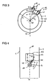
- FIG. 3 a cross-section through a gas turbine is shown, with only two Verstellleitschaufeln 4 and 4 'and two Zapfkanäle 3 and 3' are shown by way of example.
- the gas is guided from the front through the leaf level.
- the outer housing 1 with the Verstellleitschaufel 4 including pivot 5, turntable 6 and vane blade 7 is shown.
- the outer housing 1 has a first radius r 1 .
- the adjustment vanes 4 and 4 ' are framed by the inner housing 63, so that between the outer housing 1 and the inner housing 63, a Leitschaufelring 59 forms here with two Verstellleitschaufeln 4 and 4'.
- a vertically extending vertical 62 is located.
- the axis of rotation 64 and the vertical 62 form an angle ⁇ (here 15 °). This corresponds with a clock the 1 o'clock position.
- the Lips 54 radially inwardly and thereby covers the upper part of the vane blade 7.
- the lip 54 has a second radius r 2 .
- the first radius r 1 is greater than the second radius r 2 .
- the tap channel 3 has been designed by way of example rectangular.
- the axis of rotation 66 of the second Verstellleitschaufel 4 'and the vertical 62 here form an angle of 45 °.
- the angular distance ⁇ indicates the angle between the axis of rotation 64 and the axis of rotation 66. This angular distance ⁇ is 30 ° here.
- the angular distances between all axes of rotation can be the same. In a preferred embodiment, the angular distances may become continuously smaller.
- the first angular distances in a segment of a vane ring 59 are identical.
- the second angular distances are also identical, but the first angular distances are different from the second angular distances.
- the vane ring 59 may be divided into two, three or four (even more) preferably equal segments.
- FIG. 4 is a plan view of the gas turbine along the axis of rotation 64 of the Verstellleitschaufel 4 shown.
- the gas flows from bottom to top.
- Left and right outside the here vertically extending main gas path 10 is limited by the housing 1.
- the main shaft 60 of the gas turbine runs vertically.
- an inlet opening 22 to the dispensing channel 3 (not shown here, for example, rectangular) can be seen.
- the lower edge of the rectangle here forms the beginning 24 of the inlet opening 22 and the upper edge of the rectangle forms the end 52 according to the invention of the inlet opening 22.
- Below the inlet opening 22 is the Verstellleitschaufel 4 with a pivot 5, a turntable 6 and a molded thereon vane blade.
- the inventive flag 48 protrudes beyond the turntable 6 addition.
- the flag edge 50 or 50 "according to the invention is located below the inlet opening 22.
- the guide blade 7 is rotatably mounted about the rotation axis 64.
- the guide blade 7 and the main shaft 60 enclose an opening angle ⁇ .
- the vane blade 7 (or its chord) is arranged in this illustration on the main shaft 60, then the adjusting vane has an opening angle ⁇ of 0 °.
- such Verstellleitschaufeln 4 and the corresponding Zapfkanäle 3 are arranged in the high-pressure compressor of a gas turbine.
Landscapes
- Engineering & Computer Science (AREA)
- Mechanical Engineering (AREA)
- General Engineering & Computer Science (AREA)
- Chemical & Material Sciences (AREA)
- Combustion & Propulsion (AREA)
- Physics & Mathematics (AREA)
- Fluid Mechanics (AREA)
- Structures Of Non-Positive Displacement Pumps (AREA)
- Control Of Turbines (AREA)
- Turbine Rotor Nozzle Sealing (AREA)
Priority Applications (2)
| Application Number | Priority Date | Filing Date | Title |
|---|---|---|---|
| EP13196267.2A EP2881548B1 (fr) | 2013-12-09 | 2013-12-09 | Compresseur de turbine à gaz |
| US14/563,868 US10107194B2 (en) | 2013-12-09 | 2014-12-08 | Gas turbine |
Applications Claiming Priority (1)
| Application Number | Priority Date | Filing Date | Title |
|---|---|---|---|
| EP13196267.2A EP2881548B1 (fr) | 2013-12-09 | 2013-12-09 | Compresseur de turbine à gaz |
Publications (2)
| Publication Number | Publication Date |
|---|---|
| EP2881548A1 true EP2881548A1 (fr) | 2015-06-10 |
| EP2881548B1 EP2881548B1 (fr) | 2018-08-15 |
Family
ID=49726623
Family Applications (1)
| Application Number | Title | Priority Date | Filing Date |
|---|---|---|---|
| EP13196267.2A Active EP2881548B1 (fr) | 2013-12-09 | 2013-12-09 | Compresseur de turbine à gaz |
Country Status (2)
| Country | Link |
|---|---|
| US (1) | US10107194B2 (fr) |
| EP (1) | EP2881548B1 (fr) |
Cited By (3)
| Publication number | Priority date | Publication date | Assignee | Title |
|---|---|---|---|---|
| EP3109410A1 (fr) * | 2015-06-25 | 2016-12-28 | Rolls-Royce Deutschland Ltd & Co KG | Dispositif de stator pour une turbomachine comprenant un dispositif de carter et plusieurs aubes directrices |
| EP3760838A1 (fr) * | 2019-07-03 | 2021-01-06 | Raytheon Technologies Corporation | Système d'aubes directrice d'une turbine á gaz et procédé |
| WO2021083442A1 (fr) * | 2019-10-29 | 2021-05-06 | MTU Aero Engines AG | Ensemble aube directrice de turbomachine |
Families Citing this family (6)
| Publication number | Priority date | Publication date | Assignee | Title |
|---|---|---|---|---|
| US10227930B2 (en) * | 2016-03-28 | 2019-03-12 | General Electric Company | Compressor bleed systems in turbomachines and methods of extracting compressor airflow |
| DE102016212767A1 (de) | 2016-07-13 | 2018-01-18 | MTU Aero Engines AG | Verstellbares Turbomaschinen-Schaufelgitter |
| US10934943B2 (en) | 2017-04-27 | 2021-03-02 | General Electric Company | Compressor apparatus with bleed slot and supplemental flange |
| US20180313364A1 (en) * | 2017-04-27 | 2018-11-01 | General Electric Company | Compressor apparatus with bleed slot including turning vanes |
| US10626879B2 (en) | 2017-11-13 | 2020-04-21 | United Technologies Corporation | Gas turbine engine with mid-compressor bleed |
| FR3099204B1 (fr) * | 2019-07-24 | 2022-12-23 | Safran Aircraft Engines | Etage redresseur de turbomachine avec passage de fuite d’air de refroidissement a section variable suivant orientation des aubes |
Citations (6)
| Publication number | Priority date | Publication date | Assignee | Title |
|---|---|---|---|---|
| US4395195A (en) * | 1980-05-16 | 1983-07-26 | United Technologies Corporation | Shroud ring for use in a gas turbine engine |
| EP1801403A2 (fr) * | 2005-12-21 | 2007-06-27 | General Electric Company | Turbosoufflante comprenant un compresseur de suralimentation avec système de décharge compact |
| GB2445863A (en) * | 2007-01-22 | 2008-07-23 | Gen Electric | Variable vane assembly having a bushing which rotates incrementally |
| EP2055961A1 (fr) * | 2007-10-30 | 2009-05-06 | General Electric Company | Système d'extraction de fluide asymétrique |
| EP2518273A2 (fr) * | 2011-04-27 | 2012-10-31 | General Electric Company | Compresseur axial avec disposition de purge d'air provenant des étages d'aubes de stator variables |
| WO2012164224A1 (fr) * | 2011-05-31 | 2012-12-06 | Snecma | Turbomachine á vannes de décharge localisées au niveau du carter intermédiaire |
Family Cites Families (6)
| Publication number | Priority date | Publication date | Assignee | Title |
|---|---|---|---|---|
| US6327844B1 (en) | 2000-03-03 | 2001-12-11 | General Electric Company | Methods and apparatus for retaining flow restrictors within turbine engines |
| US7891943B2 (en) * | 2005-11-29 | 2011-02-22 | Ishikawajima-Harima Heavy Industries, Co. Ltd. | Stator cascade of turbo type fluid machine |
| US7966831B2 (en) | 2007-08-28 | 2011-06-28 | General Electric Company | Apparatus and method for suppressing dynamic pressure instability in bleed duct |
| US7478910B1 (en) | 2007-12-20 | 2009-01-20 | Po-Kang Lin | Liquid diagnostic contact lens |
| DE102008019603A1 (de) * | 2008-04-18 | 2009-10-22 | Rolls-Royce Deutschland Ltd & Co Kg | Strömungsmaschine mit schaufelreiheninterner Fluid-Rückführung |
| FR2931886B1 (fr) * | 2008-05-29 | 2011-10-14 | Snecma | Collecteur d'air dans une turbomachine. |
-
2013
- 2013-12-09 EP EP13196267.2A patent/EP2881548B1/fr active Active
-
2014
- 2014-12-08 US US14/563,868 patent/US10107194B2/en active Active
Patent Citations (6)
| Publication number | Priority date | Publication date | Assignee | Title |
|---|---|---|---|---|
| US4395195A (en) * | 1980-05-16 | 1983-07-26 | United Technologies Corporation | Shroud ring for use in a gas turbine engine |
| EP1801403A2 (fr) * | 2005-12-21 | 2007-06-27 | General Electric Company | Turbosoufflante comprenant un compresseur de suralimentation avec système de décharge compact |
| GB2445863A (en) * | 2007-01-22 | 2008-07-23 | Gen Electric | Variable vane assembly having a bushing which rotates incrementally |
| EP2055961A1 (fr) * | 2007-10-30 | 2009-05-06 | General Electric Company | Système d'extraction de fluide asymétrique |
| EP2518273A2 (fr) * | 2011-04-27 | 2012-10-31 | General Electric Company | Compresseur axial avec disposition de purge d'air provenant des étages d'aubes de stator variables |
| WO2012164224A1 (fr) * | 2011-05-31 | 2012-12-06 | Snecma | Turbomachine á vannes de décharge localisées au niveau du carter intermédiaire |
Cited By (5)
| Publication number | Priority date | Publication date | Assignee | Title |
|---|---|---|---|---|
| EP3109410A1 (fr) * | 2015-06-25 | 2016-12-28 | Rolls-Royce Deutschland Ltd & Co KG | Dispositif de stator pour une turbomachine comprenant un dispositif de carter et plusieurs aubes directrices |
| US10344616B2 (en) | 2015-06-25 | 2019-07-09 | Rolls-Royce Deutschland Ltd & Co Kg | Stator device for a continuous-flow machine with a housing appliance and multiple guide vanes |
| EP3760838A1 (fr) * | 2019-07-03 | 2021-01-06 | Raytheon Technologies Corporation | Système d'aubes directrice d'une turbine á gaz et procédé |
| US11105219B2 (en) | 2019-07-03 | 2021-08-31 | Raytheon Technologies Corporation | Vane angle system accuracy improvement |
| WO2021083442A1 (fr) * | 2019-10-29 | 2021-05-06 | MTU Aero Engines AG | Ensemble aube directrice de turbomachine |
Also Published As
| Publication number | Publication date |
|---|---|
| US10107194B2 (en) | 2018-10-23 |
| EP2881548B1 (fr) | 2018-08-15 |
| US20150159551A1 (en) | 2015-06-11 |
Similar Documents
| Publication | Publication Date | Title |
|---|---|---|
| EP2881548B1 (fr) | Compresseur de turbine à gaz | |
| EP2226473B1 (fr) | Elément déflecteur d'air d'un système de réglage du jeu des extrémités des aubes d'une turbine à gaz d'avion | |
| DE102009011924A1 (de) | Nebenstromkanal eines Turbofantriebwerks | |
| EP3551889B1 (fr) | Canal de retour de compresseur ou turbodétendeur multicellulaire avec aubes directrices vrillées | |
| EP0126399A1 (fr) | Conduit de fluide présentant une construction réduite | |
| EP1178183A2 (fr) | Turbine à vapeur à basse pression avec un diffuseur à canaux multiples | |
| EP3032032B1 (fr) | Aubes directrices de sortie et turboréacteur à double flux avec des aubes directrices de sortie | |
| EP2132414A1 (fr) | Agencement en feuillure | |
| DE102009054771A1 (de) | Turboverdichter | |
| DE102013215371A1 (de) | Vorrichtung und Verfahren zum Abblasen von Verdichterluft in einem Triebwerk | |
| DE102014221049A1 (de) | Anordnung und Verfahren zum Abblasen von Verdichterluft in einem Triebwerk | |
| EP3246518A1 (fr) | Aubage directeur, ensemble et procédé de montage associés | |
| EP2927503A1 (fr) | Compresseur de turbine à gaz, moteur d'avion et méthode de dimensionnement | |
| DE102015206384A1 (de) | Deckbandanordnung einer Schaufelreihe von Stator- oder Rotorschaufeln | |
| DE2359562A1 (de) | Verbundduese | |
| DE102004042295A1 (de) | Rotor für ein Triebwerk | |
| EP3376041A1 (fr) | Étage de recirculation et turbomachine à énergie fluidique radiale | |
| DE102013202786B4 (de) | Vorrichtung zum Abblasen von Verdichterluft in einem Turbofantriebwerk | |
| WO2014044363A1 (fr) | Dispositif formant palier ainsi que turbocompresseur | |
| EP3462090A1 (fr) | Buse à extension axiale pour une chambre de combustion d'un moteur | |
| EP3287640A1 (fr) | Machine à écoulement à haute performance | |
| DE112017001298T5 (de) | Mehrstufenaxialkompressor und Gasturbine | |
| WO2017067635A1 (fr) | Dispositif de réglage d'un turbocompresseur à gaz d'échappement | |
| DE112014003154T5 (de) | Spiralstruktur und Lader | |
| DE102008056855A1 (de) | Entgasungseinrichtung für flüssigkeitsgefüllte Räume mit rotierenden Bauteilen |
Legal Events
| Date | Code | Title | Description |
|---|---|---|---|
| PUAI | Public reference made under article 153(3) epc to a published international application that has entered the european phase |
Free format text: ORIGINAL CODE: 0009012 |
|
| 17P | Request for examination filed |
Effective date: 20131209 |
|
| AK | Designated contracting states |
Kind code of ref document: A1 Designated state(s): AL AT BE BG CH CY CZ DE DK EE ES FI FR GB GR HR HU IE IS IT LI LT LU LV MC MK MT NL NO PL PT RO RS SE SI SK SM TR |
|
| AX | Request for extension of the european patent |
Extension state: BA ME |
|
| REG | Reference to a national code |
Ref country code: DE Ref legal event code: R079 Ref document number: 502013010854 Country of ref document: DE Free format text: PREVIOUS MAIN CLASS: F01D0017160000 Ipc: F04D0029540000 |
|
| GRAP | Despatch of communication of intention to grant a patent |
Free format text: ORIGINAL CODE: EPIDOSNIGR1 |
|
| RIC1 | Information provided on ipc code assigned before grant |
Ipc: F04D 29/56 20060101ALI20180509BHEP Ipc: F02C 9/18 20060101ALI20180509BHEP Ipc: F02C 6/08 20060101ALI20180509BHEP Ipc: F04D 29/54 20060101AFI20180509BHEP Ipc: F01D 17/16 20060101ALI20180509BHEP |
|
| INTG | Intention to grant announced |
Effective date: 20180607 |
|
| GRAS | Grant fee paid |
Free format text: ORIGINAL CODE: EPIDOSNIGR3 |
|
| GRAA | (expected) grant |
Free format text: ORIGINAL CODE: 0009210 |
|
| AK | Designated contracting states |
Kind code of ref document: B1 Designated state(s): AL AT BE BG CH CY CZ DE DK EE ES FI FR GB GR HR HU IE IS IT LI LT LU LV MC MK MT NL NO PL PT RO RS SE SI SK SM TR |
|
| REG | Reference to a national code |
Ref country code: CH Ref legal event code: EP Ref country code: GB Ref legal event code: FG4D Free format text: NOT ENGLISH Ref country code: AT Ref legal event code: REF Ref document number: 1030118 Country of ref document: AT Kind code of ref document: T Effective date: 20180815 |
|
| REG | Reference to a national code |
Ref country code: IE Ref legal event code: FG4D Free format text: LANGUAGE OF EP DOCUMENT: GERMAN |
|
| REG | Reference to a national code |
Ref country code: DE Ref legal event code: R096 Ref document number: 502013010854 Country of ref document: DE |
|
| REG | Reference to a national code |
Ref country code: NL Ref legal event code: MP Effective date: 20180815 |
|
| REG | Reference to a national code |
Ref country code: LT Ref legal event code: MG4D |
|
| PG25 | Lapsed in a contracting state [announced via postgrant information from national office to epo] |
Ref country code: GR Free format text: LAPSE BECAUSE OF FAILURE TO SUBMIT A TRANSLATION OF THE DESCRIPTION OR TO PAY THE FEE WITHIN THE PRESCRIBED TIME-LIMIT Effective date: 20181116 Ref country code: NO Free format text: LAPSE BECAUSE OF FAILURE TO SUBMIT A TRANSLATION OF THE DESCRIPTION OR TO PAY THE FEE WITHIN THE PRESCRIBED TIME-LIMIT Effective date: 20181115 Ref country code: NL Free format text: LAPSE BECAUSE OF FAILURE TO SUBMIT A TRANSLATION OF THE DESCRIPTION OR TO PAY THE FEE WITHIN THE PRESCRIBED TIME-LIMIT Effective date: 20180815 Ref country code: IS Free format text: LAPSE BECAUSE OF FAILURE TO SUBMIT A TRANSLATION OF THE DESCRIPTION OR TO PAY THE FEE WITHIN THE PRESCRIBED TIME-LIMIT Effective date: 20181215 Ref country code: BG Free format text: LAPSE BECAUSE OF FAILURE TO SUBMIT A TRANSLATION OF THE DESCRIPTION OR TO PAY THE FEE WITHIN THE PRESCRIBED TIME-LIMIT Effective date: 20181115 Ref country code: LT Free format text: LAPSE BECAUSE OF FAILURE TO SUBMIT A TRANSLATION OF THE DESCRIPTION OR TO PAY THE FEE WITHIN THE PRESCRIBED TIME-LIMIT Effective date: 20180815 Ref country code: FI Free format text: LAPSE BECAUSE OF FAILURE TO SUBMIT A TRANSLATION OF THE DESCRIPTION OR TO PAY THE FEE WITHIN THE PRESCRIBED TIME-LIMIT Effective date: 20180815 Ref country code: RS Free format text: LAPSE BECAUSE OF FAILURE TO SUBMIT A TRANSLATION OF THE DESCRIPTION OR TO PAY THE FEE WITHIN THE PRESCRIBED TIME-LIMIT Effective date: 20180815 Ref country code: SE Free format text: LAPSE BECAUSE OF FAILURE TO SUBMIT A TRANSLATION OF THE DESCRIPTION OR TO PAY THE FEE WITHIN THE PRESCRIBED TIME-LIMIT Effective date: 20180815 |
|
| PG25 | Lapsed in a contracting state [announced via postgrant information from national office to epo] |
Ref country code: AL Free format text: LAPSE BECAUSE OF FAILURE TO SUBMIT A TRANSLATION OF THE DESCRIPTION OR TO PAY THE FEE WITHIN THE PRESCRIBED TIME-LIMIT Effective date: 20180815 Ref country code: LV Free format text: LAPSE BECAUSE OF FAILURE TO SUBMIT A TRANSLATION OF THE DESCRIPTION OR TO PAY THE FEE WITHIN THE PRESCRIBED TIME-LIMIT Effective date: 20180815 Ref country code: HR Free format text: LAPSE BECAUSE OF FAILURE TO SUBMIT A TRANSLATION OF THE DESCRIPTION OR TO PAY THE FEE WITHIN THE PRESCRIBED TIME-LIMIT Effective date: 20180815 |
|
| PG25 | Lapsed in a contracting state [announced via postgrant information from national office to epo] |
Ref country code: EE Free format text: LAPSE BECAUSE OF FAILURE TO SUBMIT A TRANSLATION OF THE DESCRIPTION OR TO PAY THE FEE WITHIN THE PRESCRIBED TIME-LIMIT Effective date: 20180815 Ref country code: PL Free format text: LAPSE BECAUSE OF FAILURE TO SUBMIT A TRANSLATION OF THE DESCRIPTION OR TO PAY THE FEE WITHIN THE PRESCRIBED TIME-LIMIT Effective date: 20180815 Ref country code: IT Free format text: LAPSE BECAUSE OF FAILURE TO SUBMIT A TRANSLATION OF THE DESCRIPTION OR TO PAY THE FEE WITHIN THE PRESCRIBED TIME-LIMIT Effective date: 20180815 Ref country code: ES Free format text: LAPSE BECAUSE OF FAILURE TO SUBMIT A TRANSLATION OF THE DESCRIPTION OR TO PAY THE FEE WITHIN THE PRESCRIBED TIME-LIMIT Effective date: 20180815 Ref country code: CZ Free format text: LAPSE BECAUSE OF FAILURE TO SUBMIT A TRANSLATION OF THE DESCRIPTION OR TO PAY THE FEE WITHIN THE PRESCRIBED TIME-LIMIT Effective date: 20180815 Ref country code: RO Free format text: LAPSE BECAUSE OF FAILURE TO SUBMIT A TRANSLATION OF THE DESCRIPTION OR TO PAY THE FEE WITHIN THE PRESCRIBED TIME-LIMIT Effective date: 20180815 |
|
| REG | Reference to a national code |
Ref country code: DE Ref legal event code: R097 Ref document number: 502013010854 Country of ref document: DE |
|
| PG25 | Lapsed in a contracting state [announced via postgrant information from national office to epo] |
Ref country code: SK Free format text: LAPSE BECAUSE OF FAILURE TO SUBMIT A TRANSLATION OF THE DESCRIPTION OR TO PAY THE FEE WITHIN THE PRESCRIBED TIME-LIMIT Effective date: 20180815 Ref country code: SM Free format text: LAPSE BECAUSE OF FAILURE TO SUBMIT A TRANSLATION OF THE DESCRIPTION OR TO PAY THE FEE WITHIN THE PRESCRIBED TIME-LIMIT Effective date: 20180815 Ref country code: DK Free format text: LAPSE BECAUSE OF FAILURE TO SUBMIT A TRANSLATION OF THE DESCRIPTION OR TO PAY THE FEE WITHIN THE PRESCRIBED TIME-LIMIT Effective date: 20180815 |
|
| PLBE | No opposition filed within time limit |
Free format text: ORIGINAL CODE: 0009261 |
|
| STAA | Information on the status of an ep patent application or granted ep patent |
Free format text: STATUS: NO OPPOSITION FILED WITHIN TIME LIMIT |
|
| 26N | No opposition filed |
Effective date: 20190516 |
|
| REG | Reference to a national code |
Ref country code: CH Ref legal event code: PL |
|
| PG25 | Lapsed in a contracting state [announced via postgrant information from national office to epo] |
Ref country code: MC Free format text: LAPSE BECAUSE OF FAILURE TO SUBMIT A TRANSLATION OF THE DESCRIPTION OR TO PAY THE FEE WITHIN THE PRESCRIBED TIME-LIMIT Effective date: 20180815 Ref country code: LU Free format text: LAPSE BECAUSE OF NON-PAYMENT OF DUE FEES Effective date: 20181209 Ref country code: SI Free format text: LAPSE BECAUSE OF FAILURE TO SUBMIT A TRANSLATION OF THE DESCRIPTION OR TO PAY THE FEE WITHIN THE PRESCRIBED TIME-LIMIT Effective date: 20180815 |
|
| REG | Reference to a national code |
Ref country code: IE Ref legal event code: MM4A |
|
| REG | Reference to a national code |
Ref country code: BE Ref legal event code: MM Effective date: 20181231 |
|
| PG25 | Lapsed in a contracting state [announced via postgrant information from national office to epo] |
Ref country code: IE Free format text: LAPSE BECAUSE OF NON-PAYMENT OF DUE FEES Effective date: 20181209 |
|
| PG25 | Lapsed in a contracting state [announced via postgrant information from national office to epo] |
Ref country code: BE Free format text: LAPSE BECAUSE OF NON-PAYMENT OF DUE FEES Effective date: 20181231 |
|
| PG25 | Lapsed in a contracting state [announced via postgrant information from national office to epo] |
Ref country code: CH Free format text: LAPSE BECAUSE OF NON-PAYMENT OF DUE FEES Effective date: 20181231 Ref country code: LI Free format text: LAPSE BECAUSE OF NON-PAYMENT OF DUE FEES Effective date: 20181231 |
|
| PG25 | Lapsed in a contracting state [announced via postgrant information from national office to epo] |
Ref country code: MT Free format text: LAPSE BECAUSE OF FAILURE TO SUBMIT A TRANSLATION OF THE DESCRIPTION OR TO PAY THE FEE WITHIN THE PRESCRIBED TIME-LIMIT Effective date: 20180815 |
|
| REG | Reference to a national code |
Ref country code: AT Ref legal event code: MM01 Ref document number: 1030118 Country of ref document: AT Kind code of ref document: T Effective date: 20181209 |
|
| PG25 | Lapsed in a contracting state [announced via postgrant information from national office to epo] |
Ref country code: TR Free format text: LAPSE BECAUSE OF FAILURE TO SUBMIT A TRANSLATION OF THE DESCRIPTION OR TO PAY THE FEE WITHIN THE PRESCRIBED TIME-LIMIT Effective date: 20180815 |
|
| PG25 | Lapsed in a contracting state [announced via postgrant information from national office to epo] |
Ref country code: AT Free format text: LAPSE BECAUSE OF NON-PAYMENT OF DUE FEES Effective date: 20181209 |
|
| PG25 | Lapsed in a contracting state [announced via postgrant information from national office to epo] |
Ref country code: PT Free format text: LAPSE BECAUSE OF FAILURE TO SUBMIT A TRANSLATION OF THE DESCRIPTION OR TO PAY THE FEE WITHIN THE PRESCRIBED TIME-LIMIT Effective date: 20180815 |
|
| PG25 | Lapsed in a contracting state [announced via postgrant information from national office to epo] |
Ref country code: CY Free format text: LAPSE BECAUSE OF FAILURE TO SUBMIT A TRANSLATION OF THE DESCRIPTION OR TO PAY THE FEE WITHIN THE PRESCRIBED TIME-LIMIT Effective date: 20180815 Ref country code: HU Free format text: LAPSE BECAUSE OF FAILURE TO SUBMIT A TRANSLATION OF THE DESCRIPTION OR TO PAY THE FEE WITHIN THE PRESCRIBED TIME-LIMIT; INVALID AB INITIO Effective date: 20131209 Ref country code: MK Free format text: LAPSE BECAUSE OF NON-PAYMENT OF DUE FEES Effective date: 20180815 |
|
| PGFP | Annual fee paid to national office [announced via postgrant information from national office to epo] |
Ref country code: GB Payment date: 20231220 Year of fee payment: 11 |
|
| PGFP | Annual fee paid to national office [announced via postgrant information from national office to epo] |
Ref country code: FR Payment date: 20231219 Year of fee payment: 11 Ref country code: DE Payment date: 20231214 Year of fee payment: 11 |