EP3246518A1 - Aubage directeur, ensemble et procédé de montage associés - Google Patents
Aubage directeur, ensemble et procédé de montage associés Download PDFInfo
- Publication number
- EP3246518A1 EP3246518A1 EP17154291.3A EP17154291A EP3246518A1 EP 3246518 A1 EP3246518 A1 EP 3246518A1 EP 17154291 A EP17154291 A EP 17154291A EP 3246518 A1 EP3246518 A1 EP 3246518A1
- Authority
- EP
- European Patent Office
- Prior art keywords
- inner ring
- vane
- blade
- ring
- turbomachine
- Prior art date
- Legal status (The legal status is an assumption and is not a legal conclusion. Google has not performed a legal analysis and makes no representation as to the accuracy of the status listed.)
- Granted
Links
- 230000000694 effects Effects 0.000 description 5
- 238000007789 sealing Methods 0.000 description 2
- 230000002411 adverse Effects 0.000 description 1
- 230000001934 delay Effects 0.000 description 1
- 230000003111 delayed effect Effects 0.000 description 1
- 230000002939 deleterious effect Effects 0.000 description 1
- 230000002349 favourable effect Effects 0.000 description 1
- 239000012530 fluid Substances 0.000 description 1
- 230000004941 influx Effects 0.000 description 1
- 238000011144 upstream manufacturing Methods 0.000 description 1
Images

Classifications
-
- F—MECHANICAL ENGINEERING; LIGHTING; HEATING; WEAPONS; BLASTING
- F01—MACHINES OR ENGINES IN GENERAL; ENGINE PLANTS IN GENERAL; STEAM ENGINES
- F01D—NON-POSITIVE DISPLACEMENT MACHINES OR ENGINES, e.g. STEAM TURBINES
- F01D9/00—Stators
- F01D9/02—Nozzles; Nozzle boxes; Stator blades; Guide conduits, e.g. individual nozzles
- F01D9/04—Nozzles; Nozzle boxes; Stator blades; Guide conduits, e.g. individual nozzles forming ring or sector
- F01D9/041—Nozzles; Nozzle boxes; Stator blades; Guide conduits, e.g. individual nozzles forming ring or sector using blades
-
- F—MECHANICAL ENGINEERING; LIGHTING; HEATING; WEAPONS; BLASTING
- F04—POSITIVE - DISPLACEMENT MACHINES FOR LIQUIDS; PUMPS FOR LIQUIDS OR ELASTIC FLUIDS
- F04D—NON-POSITIVE-DISPLACEMENT PUMPS
- F04D29/00—Details, component parts, or accessories
- F04D29/66—Combating cavitation, whirls, noise, vibration or the like; Balancing
- F04D29/68—Combating cavitation, whirls, noise, vibration or the like; Balancing by influencing boundary layers
- F04D29/681—Combating cavitation, whirls, noise, vibration or the like; Balancing by influencing boundary layers especially adapted for elastic fluid pumps
-
- F—MECHANICAL ENGINEERING; LIGHTING; HEATING; WEAPONS; BLASTING
- F01—MACHINES OR ENGINES IN GENERAL; ENGINE PLANTS IN GENERAL; STEAM ENGINES
- F01D—NON-POSITIVE DISPLACEMENT MACHINES OR ENGINES, e.g. STEAM TURBINES
- F01D17/00—Regulating or controlling by varying flow
- F01D17/10—Final actuators
- F01D17/12—Final actuators arranged in stator parts
- F01D17/14—Final actuators arranged in stator parts varying effective cross-sectional area of nozzles or guide conduits
- F01D17/16—Final actuators arranged in stator parts varying effective cross-sectional area of nozzles or guide conduits by means of nozzle vanes
- F01D17/162—Final actuators arranged in stator parts varying effective cross-sectional area of nozzles or guide conduits by means of nozzle vanes for axial flow, i.e. the vanes turning around axes which are essentially perpendicular to the rotor centre line
-
- F—MECHANICAL ENGINEERING; LIGHTING; HEATING; WEAPONS; BLASTING
- F01—MACHINES OR ENGINES IN GENERAL; ENGINE PLANTS IN GENERAL; STEAM ENGINES
- F01D—NON-POSITIVE DISPLACEMENT MACHINES OR ENGINES, e.g. STEAM TURBINES
- F01D5/00—Blades; Blade-carrying members; Heating, heat-insulating, cooling or antivibration means on the blades or the members
- F01D5/12—Blades
- F01D5/14—Form or construction
- F01D5/141—Shape, i.e. outer, aerodynamic form
- F01D5/142—Shape, i.e. outer, aerodynamic form of the blades of successive rotor or stator blade-rows
- F01D5/143—Contour of the outer or inner working fluid flow path wall, i.e. shroud or hub contour
-
- F—MECHANICAL ENGINEERING; LIGHTING; HEATING; WEAPONS; BLASTING
- F04—POSITIVE - DISPLACEMENT MACHINES FOR LIQUIDS; PUMPS FOR LIQUIDS OR ELASTIC FLUIDS
- F04D—NON-POSITIVE-DISPLACEMENT PUMPS
- F04D29/00—Details, component parts, or accessories
- F04D29/40—Casings; Connections of working fluid
- F04D29/52—Casings; Connections of working fluid for axial pumps
- F04D29/54—Fluid-guiding means, e.g. diffusers
- F04D29/541—Specially adapted for elastic fluid pumps
- F04D29/542—Bladed diffusers
-
- F—MECHANICAL ENGINEERING; LIGHTING; HEATING; WEAPONS; BLASTING
- F04—POSITIVE - DISPLACEMENT MACHINES FOR LIQUIDS; PUMPS FOR LIQUIDS OR ELASTIC FLUIDS
- F04D—NON-POSITIVE-DISPLACEMENT PUMPS
- F04D29/00—Details, component parts, or accessories
- F04D29/40—Casings; Connections of working fluid
- F04D29/52—Casings; Connections of working fluid for axial pumps
- F04D29/54—Fluid-guiding means, e.g. diffusers
- F04D29/56—Fluid-guiding means, e.g. diffusers adjustable
- F04D29/563—Fluid-guiding means, e.g. diffusers adjustable specially adapted for elastic fluid pumps
-
- F—MECHANICAL ENGINEERING; LIGHTING; HEATING; WEAPONS; BLASTING
- F05—INDEXING SCHEMES RELATING TO ENGINES OR PUMPS IN VARIOUS SUBCLASSES OF CLASSES F01-F04
- F05D—INDEXING SCHEME FOR ASPECTS RELATING TO NON-POSITIVE-DISPLACEMENT MACHINES OR ENGINES, GAS-TURBINES OR JET-PROPULSION PLANTS
- F05D2220/00—Application
- F05D2220/30—Application in turbines
- F05D2220/32—Application in turbines in gas turbines
-
- F—MECHANICAL ENGINEERING; LIGHTING; HEATING; WEAPONS; BLASTING
- F05—INDEXING SCHEMES RELATING TO ENGINES OR PUMPS IN VARIOUS SUBCLASSES OF CLASSES F01-F04
- F05D—INDEXING SCHEME FOR ASPECTS RELATING TO NON-POSITIVE-DISPLACEMENT MACHINES OR ENGINES, GAS-TURBINES OR JET-PROPULSION PLANTS
- F05D2250/00—Geometry
- F05D2250/30—Arrangement of components
- F05D2250/31—Arrangement of components according to the direction of their main axis or their axis of rotation
- F05D2250/314—Arrangement of components according to the direction of their main axis or their axis of rotation the axes being inclined in relation to each other
-
- F—MECHANICAL ENGINEERING; LIGHTING; HEATING; WEAPONS; BLASTING
- F05—INDEXING SCHEMES RELATING TO ENGINES OR PUMPS IN VARIOUS SUBCLASSES OF CLASSES F01-F04
- F05D—INDEXING SCHEME FOR ASPECTS RELATING TO NON-POSITIVE-DISPLACEMENT MACHINES OR ENGINES, GAS-TURBINES OR JET-PROPULSION PLANTS
- F05D2250/00—Geometry
- F05D2250/60—Structure; Surface texture
- F05D2250/61—Structure; Surface texture corrugated
-
- F—MECHANICAL ENGINEERING; LIGHTING; HEATING; WEAPONS; BLASTING
- F05—INDEXING SCHEMES RELATING TO ENGINES OR PUMPS IN VARIOUS SUBCLASSES OF CLASSES F01-F04
- F05D—INDEXING SCHEME FOR ASPECTS RELATING TO NON-POSITIVE-DISPLACEMENT MACHINES OR ENGINES, GAS-TURBINES OR JET-PROPULSION PLANTS
- F05D2250/00—Geometry
- F05D2250/70—Shape
- F05D2250/71—Shape curved
- F05D2250/711—Shape curved convex
-
- F—MECHANICAL ENGINEERING; LIGHTING; HEATING; WEAPONS; BLASTING
- F05—INDEXING SCHEMES RELATING TO ENGINES OR PUMPS IN VARIOUS SUBCLASSES OF CLASSES F01-F04
- F05D—INDEXING SCHEME FOR ASPECTS RELATING TO NON-POSITIVE-DISPLACEMENT MACHINES OR ENGINES, GAS-TURBINES OR JET-PROPULSION PLANTS
- F05D2250/00—Geometry
- F05D2250/70—Shape
- F05D2250/71—Shape curved
- F05D2250/712—Shape curved concave
-
- Y—GENERAL TAGGING OF NEW TECHNOLOGICAL DEVELOPMENTS; GENERAL TAGGING OF CROSS-SECTIONAL TECHNOLOGIES SPANNING OVER SEVERAL SECTIONS OF THE IPC; TECHNICAL SUBJECTS COVERED BY FORMER USPC CROSS-REFERENCE ART COLLECTIONS [XRACs] AND DIGESTS
- Y02—TECHNOLOGIES OR APPLICATIONS FOR MITIGATION OR ADAPTATION AGAINST CLIMATE CHANGE
- Y02T—CLIMATE CHANGE MITIGATION TECHNOLOGIES RELATED TO TRANSPORTATION
- Y02T50/00—Aeronautics or air transport
- Y02T50/60—Efficient propulsion technologies, e.g. for aircraft
Definitions
- the invention relates to a vane ring with an inner ring and a plurality of vanes, a vane ring assembly and a vane ring type fluid machine.
- Turbomachines such as aircraft engines and stationary gas turbines regularly have at least one compressor-side and / or one turbine-side stator blade row with a multiplicity of guide vanes.
- the vane row forms an inner ring with a so-called vane ring.
- the inner ring preferably has a plurality of recesses in the radial direction, in each of which a blade plate of a guide blade is inserted.
- a radially outer bearing of the vanes and their operation can be done via adjustment pins of the vanes, which can cooperate with a corresponding adjustment on the outer housing.
- a seal carrier is preferably guided, which is provided with sealing elements or inlet pads, facing the rotor-side sealing ribs.
- the object of the present invention is to provide a vane ring or a turbomachine in which the leakage between the inner ring and an inserted guide vane is reduced.
- An inventive vane ring for a turbomachine has a guide vane row with a plurality of pivotable vanes and an inner ring with one of the plurality of vanes facing inner ring surface.
- the vanes each have an airfoil and a paddle.
- the vane plates In a nominal and / or in a maximum opening position of the guide vane, the vane plates (on their side facing the airfoil) have a front and a rear surface area in the direction of an intended main flow flowing through the turbomachine;
- the front and / or the rear surface region of at least one of the blade plates in this case has a radial offset relative to the inner ring surface (relative to a central axis of the inner ring).
- a “nominal open position” is to be understood as meaning a rotational position of the vane, in which, for two points which are on the edge of the surface of the vane plate with respect to the longitudinal axis of the airfoil, about which the vane is pivotable, diametrically opposite and with the central axis of the inner ring lie in a common plane, a maximum possible difference in the distances of the points to the central axis of the inner ring, which coincides in the intended installed state with the axis of rotation or machine axis of the turbomachine, is achieved.
- a turbomachine In a turbomachine, the setting of such a nominal opening position is preferably provided for the situation in which the turbomachine has a rotational speed for which it is designed.
- an aircraft engine as turbomachine
- a maximum open position can be set, for example, when the main flow (as compared with a guide vane pivoted on the other hand) undergoes a minimal change in direction through the airfoil.
- the setting of such a maximum opening position can be provided, for example, at a start of an aircraft engine (as turbomachine).
- the inner ring surface facing the guide vanes and the surface of the bucket disk facing its associated airfoil and therefore also the guide vanes thus do not run along a common, smooth surface, but the front and / or rear surface region of the bucket disk surface is offset from the inner ring surface, so that Thus, at an offset point, a step is formed in the radial direction between the said surfaces (in relation to the central axis of the inner ring).
- An assembly according to the invention for a vane ring comprises an inner ring and at least one vane insertable into a recess of the inner ring.
- Their plate comprises a - in the direction of a planned, flowing through the turbomachine Mainstream - front and rear surface area.
- Functionally assembled according to the invention an assembly according to the invention results in a guide vane ring according to the invention according to one of the embodiments disclosed in this document.
- a turbomachine according to the invention has a guide vane ring according to the invention according to one of the embodiments disclosed in this document.
- the surface area of the paddle (in the nominal and / or the maximum opening position of the guide blade) is lowered relative to the inner ring surface.
- the front (the airfoil facing) surface region of the blade plate in this embodiment is preferably recessed in a surrounding the blade plate recess of the inner ring.
- An air stream entering the turbomachine is thereby advantageously guided over the front surface region, so that air emerging from the gap is delayed in this region before mixing with the main stream.
- a suction effect of air in the gap between the blade plate and inner ring (in the recess) is reduced in the rear surface area of the blade plate. Overall, so the leakage air flow is reduced.
- the rear surface area of the blade plate (in the nominal and / or maximum) opening position of the guide blade) can be raised relative to the inner ring surface.
- the rear surface region of the blade plate preferably projects out of a recess of the inner ring surrounding the blade plate, for example into the main flow.
- a main flow which has entered the turbomachine is thus advantageously passed away via the gap between the rear surface region of the blade plate and the inner ring. An influx of air into the gap is thereby reduced.
- Embodiments in which the offset is advantageous, in particular in the case of the nominal and / or maximum opening position of the guide vane, of the front and / or rear are advantageous Surface area relative to the inner ring surface (height) (as an amount, thus unsigned value) between 1mm and 4mm and / or 3% to 15%, preferably 5% to 10% of the diameter of the blade plate or a channel height (or a radius of the vane ring) is.
- the height of the offset can be measured parallel to the guide blade axis (or radially relative to the inner ring) and preferably at a location at which the height is maximum. These dimensions are particularly favorable, on the one hand to guide the main flow in the turbomachine and on the other hand to achieve the described leakage reduction. Laterally of the maximum points, the offset flattens off preferably continuously.
- both mentioned surface areas of the airfoil form an offset to the inner ring surface
- the respective (step) heights may be the same or different.
- the offsets can be adapted to the flow guidance caused by the inner ring surface.
- the blade plate may have a substantially flat surface, a substantially convex, a substantially concave or a corrugated surface (preferably with at least one concave and convex portion) on the side facing the blade.
- the paddle can be adapted to the inner ring surface and thereby guide the main flow suitably via the offset between the front and rear surface area and inner ring surface.
- FIG. 1 a section of a conventional vane ring is shown.
- the section comprises a part of an inner ring 10 with a recess 11 into which a blade plate 21 of a guide vane 20 is inserted.
- the guide blade 20 comprises, in addition to the blade plate 21, an airfoil blade 24.
- the guide blade can be pivoted about its longitudinal axis A, which extends in the radial direction r relative to the inner ring (or its central axis (not shown)).
- the vane 20 is in a nominal open position.
- An intended main stream runs in a direction R.
- the vane 20 or its blade 24 facing (and thus facing away from a central axis, not shown, of the inner ring) are an inner ring surface 12 and a surface 22 of the blade plate. Both lie together along a smooth surface and are separated from each other only by a gap 30 substantially step-free.
- FIG. 2 a section of a vane ring according to the invention is shown in an analogous representation; Elements similar to those of the FIG. 1 correspond to illustrated vane ring are each provided with the same reference numerals; for their description is on the the FIG. 1 directed.
- the surface 21 of the vane 20 has in the in FIG. 2 shown embodiment (seen with respect to the intended main flow direction R) front surface portion 22a and a rear surface portion 22b.
- In the illustrated embodiment form both surface areas 22a, 22b (in the nominal Open position of the guide vane) at the gap 30 a (relative to the central axis of the inner ring) radial offset 31a and 31b to the inner ring surface 12:
- the front surface portion 22a is compared to the inner ring surface 12 (or into the recess for the blade inside) lowered
- the rear surface portion 22b is raised relative to the inner ring surface 12 (thus protruding from the recess for the blade plate).
- the offset 31a delays the mixing of a leakage flow, which in this area exits through the gap 30, with the main flow. This also minimizes deleterious effect on the main flow and also reduces a suction effect of air into the gap that occurs, in particular, between the rear surface area 22b and the inner ring surface 12.
- the offset 31b additionally reduces the ingress of air into the gap 30 in this area because the main flow is directed across the gap by this offset 31b.
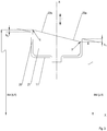
- FIG. 3 a vane ring according to an embodiment of the present invention is shown in a sectional view.
- the elements described are again provided with the same reference numerals, and for their description reference is made to the above explanations.
- the illustrated blade plate 21 is in the FIG. 3 represented in the nominal open position of the associated vane. To illustrate this opening position are in the figure (not to scale) the central axis X of the vane ring, the points p and q and their respective distances dist (p, X) and dist (q, X) to the central axis X drawn; the points p, q lie diametrically opposite each other on the edge of the surface of the blade plate 21 and with respect to the longitudinal axis A of the blade around which the blade is pivotable, in a common meridian plane of the central axis X.
- the offset between the point p (in the front surface portion 22a of the blade plate 21) and the inner ring surface (relative to the inner ring) in the radial direction r a step height h 1 , wherein the magnitude, that is not signed value is considered ,
- the heights h 1 and h 2 are each preferably in a range of 3% to 15% of the diameter of the blade plate, more preferably in a range of 5% to 10% of the diameter of the blade plate.
- the heights h 1 and h 2 are between 1 mm and 4 mm, more preferably between 1.5 and 2.5 mm.
- the height h 1 is greater than the height h 2 , so that the inventive reduction of the leakage flowing through the recess leakage effect mainly by the reduced mixing in the front surface portion 22 a of the blade plate and the resulting reduced suction effect of air into the gap 30 and while a deflection of the main flow through the surface of the blade plate (in particular in the rear surface portion 22b) is kept low.
- the blade plate has a substantially planar surface.
- the surface of the paddle (at least in one or more sections) may be convex (toward the airfoil) or concave (away from the airfoil), or have a corrugated surface (eg, sinusoidal in cross-section), and / or the front and rear surface areas may be at different levels. In this way, the blade plate surface may be adapted to the inner ring surface 22.
- An inventive vane ring for a turbomachine minimizes a leakage flow that passes through a recess 11, in which the paddle a Guide vane is used.
- the vane ring has a guide vane row with a plurality of guide vanes 20, each with an airfoil 24 and a blade plate 21 and an inner ring 10 with one of the plurality of vanes facing inner ring surface 12.
- the blade plates 21 have, viewed in the direction R of a provided main flow flowing through the turbomachine, a front and a rear surface region 22a, 22b.
- the front and / or the rear surface region 22a, 22b of at least one of the blade plates has a radial offset 31a, 31b relative to the inner ring surface 12 in a nominal and / or a maximum opening position of the stator blade (relative to a central axis X of the inner ring).
Landscapes
- Engineering & Computer Science (AREA)
- Mechanical Engineering (AREA)
- General Engineering & Computer Science (AREA)
- Physics & Mathematics (AREA)
- Fluid Mechanics (AREA)
- Structures Of Non-Positive Displacement Pumps (AREA)
Applications Claiming Priority (1)
| Application Number | Priority Date | Filing Date | Title |
|---|---|---|---|
| DE102016207212.9A DE102016207212A1 (de) | 2016-04-28 | 2016-04-28 | Leitschaufelkranz für eine Strömungsmaschine |
Publications (2)
| Publication Number | Publication Date |
|---|---|
| EP3246518A1 true EP3246518A1 (fr) | 2017-11-22 |
| EP3246518B1 EP3246518B1 (fr) | 2023-09-20 |
Family
ID=57960316
Family Applications (1)
| Application Number | Title | Priority Date | Filing Date |
|---|---|---|---|
| EP17154291.3A Active EP3246518B1 (fr) | 2016-04-28 | 2017-02-02 | Anneau aubagé directeur pour une turbomachine et turbomachine |
Country Status (3)
| Country | Link |
|---|---|
| US (1) | US10677076B2 (fr) |
| EP (1) | EP3246518B1 (fr) |
| DE (1) | DE102016207212A1 (fr) |
Cited By (2)
| Publication number | Priority date | Publication date | Assignee | Title |
|---|---|---|---|---|
| WO2022022780A1 (fr) * | 2020-07-30 | 2022-02-03 | MTU Aero Engines AG | Agencement d'aube directrice pour turbomachine, module de compression et turbomachine associée |
| EP4006315A1 (fr) * | 2020-11-27 | 2022-06-01 | Pratt & Whitney Canada Corp. | Aube de guidage à orientation variable pour un moteur de turbine à gaz, ensemble d'aubes directrices variables pour un moteur à turbine à gaz et procédé d'exploitation associé |
Families Citing this family (3)
| Publication number | Priority date | Publication date | Assignee | Title |
|---|---|---|---|---|
| DE102016201766A1 (de) * | 2016-02-05 | 2017-08-10 | MTU Aero Engines AG | Leitschaufelsystem für eine Strömungsmaschine |
| FR3094746B1 (fr) * | 2019-04-03 | 2021-03-05 | Safran Aircraft Engines | Aube de stator a calage variable pour une turbomachine d’aeronef |
| DE102020210094A1 (de) | 2020-08-10 | 2022-02-10 | MTU Aero Engines AG | Verstellbare Leitschaufelanordnung |
Citations (3)
| Publication number | Priority date | Publication date | Assignee | Title |
|---|---|---|---|---|
| EP1188933A1 (fr) * | 2000-09-18 | 2002-03-20 | Snecma Moteurs | Dispositif de commande d'aubes à calage variable |
| WO2010079204A1 (fr) * | 2009-01-09 | 2010-07-15 | Snecma | Aube a calage variable pour etage de redresseur, comprenant une plateforme interne non circulaire |
| EP2884054A1 (fr) * | 2013-12-10 | 2015-06-17 | MTU Aero Engines GmbH | Aube de guidage variable avec cône tronqué dans un ensemble palier |
Family Cites Families (13)
| Publication number | Priority date | Publication date | Assignee | Title |
|---|---|---|---|---|
| FR2742799B1 (fr) * | 1995-12-20 | 1998-01-16 | Snecma | Palier d'extremite interne d'aube pivotante |
| GB0504588D0 (en) * | 2005-03-05 | 2005-04-13 | Rolls Royce Plc | Pivot ring |
| US8511978B2 (en) | 2006-05-02 | 2013-08-20 | United Technologies Corporation | Airfoil array with an endwall depression and components of the array |
| GB2459462B (en) * | 2008-04-23 | 2010-09-01 | Rolls Royce Plc | A variable stator vane |
| US8647067B2 (en) | 2008-12-09 | 2014-02-11 | General Electric Company | Banked platform turbine blade |
| US8459956B2 (en) | 2008-12-24 | 2013-06-11 | General Electric Company | Curved platform turbine blade |
| EP2405104A1 (fr) | 2010-07-08 | 2012-01-11 | Siemens Aktiengesellschaft | Compresseur et moteur à turbine à gaz associé |
| US20130011265A1 (en) | 2011-07-05 | 2013-01-10 | Alstom Technology Ltd. | Chevron platform turbine vane |
| US8864452B2 (en) | 2011-07-12 | 2014-10-21 | Siemens Energy, Inc. | Flow directing member for gas turbine engine |
| US9085985B2 (en) | 2012-03-23 | 2015-07-21 | General Electric Company | Scalloped surface turbine stage |
| WO2014130214A1 (fr) | 2013-02-22 | 2014-08-28 | United Technologies Corporation | Ensemble d'aubes fixes de stator, et procédé associé |
| DE102013222980A1 (de) * | 2013-11-12 | 2015-06-11 | MTU Aero Engines AG | Leitschaufel für eine Strömungsmaschine mit einer Dichtungsvorrichtung, Leitrad sowie Strömungsmaschine |
| EP3090126B1 (fr) | 2013-11-22 | 2022-05-11 | Raytheon Technologies Corporation | Composant de moteur à turbine à gaz avec tranchée de façonnage de paroi d'extrémité |
-
2016
- 2016-04-28 DE DE102016207212.9A patent/DE102016207212A1/de not_active Withdrawn
-
2017
- 2017-02-02 EP EP17154291.3A patent/EP3246518B1/fr active Active
- 2017-04-26 US US15/497,902 patent/US10677076B2/en active Active
Patent Citations (3)
| Publication number | Priority date | Publication date | Assignee | Title |
|---|---|---|---|---|
| EP1188933A1 (fr) * | 2000-09-18 | 2002-03-20 | Snecma Moteurs | Dispositif de commande d'aubes à calage variable |
| WO2010079204A1 (fr) * | 2009-01-09 | 2010-07-15 | Snecma | Aube a calage variable pour etage de redresseur, comprenant une plateforme interne non circulaire |
| EP2884054A1 (fr) * | 2013-12-10 | 2015-06-17 | MTU Aero Engines GmbH | Aube de guidage variable avec cône tronqué dans un ensemble palier |
Cited By (3)
| Publication number | Priority date | Publication date | Assignee | Title |
|---|---|---|---|---|
| WO2022022780A1 (fr) * | 2020-07-30 | 2022-02-03 | MTU Aero Engines AG | Agencement d'aube directrice pour turbomachine, module de compression et turbomachine associée |
| EP4006315A1 (fr) * | 2020-11-27 | 2022-06-01 | Pratt & Whitney Canada Corp. | Aube de guidage à orientation variable pour un moteur de turbine à gaz, ensemble d'aubes directrices variables pour un moteur à turbine à gaz et procédé d'exploitation associé |
| US11572798B2 (en) | 2020-11-27 | 2023-02-07 | Pratt & Whitney Canada Corp. | Variable guide vane for gas turbine engine |
Also Published As
| Publication number | Publication date |
|---|---|
| US20170314406A1 (en) | 2017-11-02 |
| EP3246518B1 (fr) | 2023-09-20 |
| US10677076B2 (en) | 2020-06-09 |
| DE102016207212A1 (de) | 2017-11-02 |
Similar Documents
| Publication | Publication Date | Title |
|---|---|---|
| EP3246518B1 (fr) | Anneau aubagé directeur pour une turbomachine et turbomachine | |
| DE4242494C1 (en) | Adjustable flow-guide for engine exhaust turbocharger - has axially-adjustable annular insert in sectors forming different kinds of guide grilles supplied simultaneously by spiral passages | |
| EP0598174B1 (fr) | Turbosoufflante pour une machine à combustion interne | |
| EP0799973B1 (fr) | Contour de paroi pour une turbomachine axiale | |
| EP1260678A1 (fr) | Dispositif de refroidissement pour les éléments d'une turbine à gaz | |
| EP0903468A1 (fr) | Bandage annulaire pour turbine axiale | |
| EP2881548B1 (fr) | Compresseur de turbine à gaz | |
| DE112007002564T5 (de) | Diffusor und Auslasssystem für Turbine | |
| CH697806A2 (de) | Turbinenschaufel-Deckbandkantenprofil. | |
| WO2005106207A1 (fr) | Aube de compresseur et compresseur | |
| DE102006048933A1 (de) | Anordnung zur Strömungsbeeinflussung | |
| WO2019063384A1 (fr) | Diffuseur pour compresseur | |
| EP1163425A1 (fr) | Aube de turbine | |
| EP2132414A1 (fr) | Agencement en feuillure | |
| DE102016124806A1 (de) | Turbinen-Laufschaufelanordnung für eine Gasturbine und Verfahren zum Bereitstellen von Dichtluft in einer Turbinen-Laufschaufelanordnung | |
| DE102020201830B4 (de) | Leitschaufel-diffusor und zentrifugalkompressor | |
| DE102015206384A1 (de) | Deckbandanordnung einer Schaufelreihe von Stator- oder Rotorschaufeln | |
| EP3401504B1 (fr) | Grille d'aube | |
| DE60305011T2 (de) | Verbesserte schaufelausführung zur verwendung in turboladern mit variabler geometrie | |
| EP2607625A1 (fr) | Turbomachine et étage de turbomachine | |
| EP3358135B1 (fr) | Contournage d'une plate-forme de grille d'aube | |
| WO2019034740A1 (fr) | Diffuseur pour compresseur radial | |
| DE102018206601A1 (de) | Schaufel, Schaufelsegment und Baugruppe für eine Turbomaschine und Turbomaschine | |
| DE112017005661T5 (de) | Variable Düseneinheit und Turbolader | |
| EP2963243B1 (fr) | Turbomachine avec aubes rotoriques avec extrémités abaissées en direction du bord de fuite |
Legal Events
| Date | Code | Title | Description |
|---|---|---|---|
| PUAI | Public reference made under article 153(3) epc to a published international application that has entered the european phase |
Free format text: ORIGINAL CODE: 0009012 |
|
| STAA | Information on the status of an ep patent application or granted ep patent |
Free format text: STATUS: THE APPLICATION HAS BEEN PUBLISHED |
|
| AK | Designated contracting states |
Kind code of ref document: A1 Designated state(s): AL AT BE BG CH CY CZ DE DK EE ES FI FR GB GR HR HU IE IS IT LI LT LU LV MC MK MT NL NO PL PT RO RS SE SI SK SM TR |
|
| AX | Request for extension of the european patent |
Extension state: BA ME |
|
| STAA | Information on the status of an ep patent application or granted ep patent |
Free format text: STATUS: REQUEST FOR EXAMINATION WAS MADE |
|
| 17P | Request for examination filed |
Effective date: 20180522 |
|
| RBV | Designated contracting states (corrected) |
Designated state(s): AL AT BE BG CH CY CZ DE DK EE ES FI FR GB GR HR HU IE IS IT LI LT LU LV MC MK MT NL NO PL PT RO RS SE SI SK SM TR |
|
| STAA | Information on the status of an ep patent application or granted ep patent |
Free format text: STATUS: EXAMINATION IS IN PROGRESS |
|
| 17Q | First examination report despatched |
Effective date: 20210721 |
|
| STAA | Information on the status of an ep patent application or granted ep patent |
Free format text: STATUS: EXAMINATION IS IN PROGRESS |
|
| GRAP | Despatch of communication of intention to grant a patent |
Free format text: ORIGINAL CODE: EPIDOSNIGR1 |
|
| STAA | Information on the status of an ep patent application or granted ep patent |
Free format text: STATUS: GRANT OF PATENT IS INTENDED |
|
| INTG | Intention to grant announced |
Effective date: 20230424 |
|
| GRAS | Grant fee paid |
Free format text: ORIGINAL CODE: EPIDOSNIGR3 |
|
| GRAA | (expected) grant |
Free format text: ORIGINAL CODE: 0009210 |
|
| STAA | Information on the status of an ep patent application or granted ep patent |
Free format text: STATUS: THE PATENT HAS BEEN GRANTED |
|
| AK | Designated contracting states |
Kind code of ref document: B1 Designated state(s): AL AT BE BG CH CY CZ DE DK EE ES FI FR GB GR HR HU IE IS IT LI LT LU LV MC MK MT NL NO PL PT RO RS SE SI SK SM TR |
|
| REG | Reference to a national code |
Ref country code: GB Ref legal event code: FG4D Free format text: NOT ENGLISH |
|
| REG | Reference to a national code |
Ref country code: CH Ref legal event code: EP |
|
| REG | Reference to a national code |
Ref country code: IE Ref legal event code: FG4D Free format text: LANGUAGE OF EP DOCUMENT: GERMAN |
|
| REG | Reference to a national code |
Ref country code: DE Ref legal event code: R096 Ref document number: 502017015389 Country of ref document: DE |
|
| REG | Reference to a national code |
Ref country code: LT Ref legal event code: MG9D |
|
| PG25 | Lapsed in a contracting state [announced via postgrant information from national office to epo] |
Ref country code: GR Free format text: LAPSE BECAUSE OF FAILURE TO SUBMIT A TRANSLATION OF THE DESCRIPTION OR TO PAY THE FEE WITHIN THE PRESCRIBED TIME-LIMIT Effective date: 20231221 |
|
| REG | Reference to a national code |
Ref country code: NL Ref legal event code: MP Effective date: 20230920 |
|
| PG25 | Lapsed in a contracting state [announced via postgrant information from national office to epo] |
Ref country code: SE Free format text: LAPSE BECAUSE OF FAILURE TO SUBMIT A TRANSLATION OF THE DESCRIPTION OR TO PAY THE FEE WITHIN THE PRESCRIBED TIME-LIMIT Effective date: 20230920 Ref country code: RS Free format text: LAPSE BECAUSE OF FAILURE TO SUBMIT A TRANSLATION OF THE DESCRIPTION OR TO PAY THE FEE WITHIN THE PRESCRIBED TIME-LIMIT Effective date: 20230920 Ref country code: NO Free format text: LAPSE BECAUSE OF FAILURE TO SUBMIT A TRANSLATION OF THE DESCRIPTION OR TO PAY THE FEE WITHIN THE PRESCRIBED TIME-LIMIT Effective date: 20231220 Ref country code: LV Free format text: LAPSE BECAUSE OF FAILURE TO SUBMIT A TRANSLATION OF THE DESCRIPTION OR TO PAY THE FEE WITHIN THE PRESCRIBED TIME-LIMIT Effective date: 20230920 Ref country code: LT Free format text: LAPSE BECAUSE OF FAILURE TO SUBMIT A TRANSLATION OF THE DESCRIPTION OR TO PAY THE FEE WITHIN THE PRESCRIBED TIME-LIMIT Effective date: 20230920 Ref country code: HR Free format text: LAPSE BECAUSE OF FAILURE TO SUBMIT A TRANSLATION OF THE DESCRIPTION OR TO PAY THE FEE WITHIN THE PRESCRIBED TIME-LIMIT Effective date: 20230920 Ref country code: GR Free format text: LAPSE BECAUSE OF FAILURE TO SUBMIT A TRANSLATION OF THE DESCRIPTION OR TO PAY THE FEE WITHIN THE PRESCRIBED TIME-LIMIT Effective date: 20231221 Ref country code: FI Free format text: LAPSE BECAUSE OF FAILURE TO SUBMIT A TRANSLATION OF THE DESCRIPTION OR TO PAY THE FEE WITHIN THE PRESCRIBED TIME-LIMIT Effective date: 20230920 |
|
| PG25 | Lapsed in a contracting state [announced via postgrant information from national office to epo] |
Ref country code: NL Free format text: LAPSE BECAUSE OF FAILURE TO SUBMIT A TRANSLATION OF THE DESCRIPTION OR TO PAY THE FEE WITHIN THE PRESCRIBED TIME-LIMIT Effective date: 20230920 |
|
| PG25 | Lapsed in a contracting state [announced via postgrant information from national office to epo] |
Ref country code: IS Free format text: LAPSE BECAUSE OF FAILURE TO SUBMIT A TRANSLATION OF THE DESCRIPTION OR TO PAY THE FEE WITHIN THE PRESCRIBED TIME-LIMIT Effective date: 20240120 |
|
| PG25 | Lapsed in a contracting state [announced via postgrant information from national office to epo] |
Ref country code: ES Free format text: LAPSE BECAUSE OF FAILURE TO SUBMIT A TRANSLATION OF THE DESCRIPTION OR TO PAY THE FEE WITHIN THE PRESCRIBED TIME-LIMIT Effective date: 20230920 |
|
| PG25 | Lapsed in a contracting state [announced via postgrant information from national office to epo] |
Ref country code: SM Free format text: LAPSE BECAUSE OF FAILURE TO SUBMIT A TRANSLATION OF THE DESCRIPTION OR TO PAY THE FEE WITHIN THE PRESCRIBED TIME-LIMIT Effective date: 20230920 Ref country code: RO Free format text: LAPSE BECAUSE OF FAILURE TO SUBMIT A TRANSLATION OF THE DESCRIPTION OR TO PAY THE FEE WITHIN THE PRESCRIBED TIME-LIMIT Effective date: 20230920 Ref country code: IS Free format text: LAPSE BECAUSE OF FAILURE TO SUBMIT A TRANSLATION OF THE DESCRIPTION OR TO PAY THE FEE WITHIN THE PRESCRIBED TIME-LIMIT Effective date: 20240120 Ref country code: ES Free format text: LAPSE BECAUSE OF FAILURE TO SUBMIT A TRANSLATION OF THE DESCRIPTION OR TO PAY THE FEE WITHIN THE PRESCRIBED TIME-LIMIT Effective date: 20230920 Ref country code: EE Free format text: LAPSE BECAUSE OF FAILURE TO SUBMIT A TRANSLATION OF THE DESCRIPTION OR TO PAY THE FEE WITHIN THE PRESCRIBED TIME-LIMIT Effective date: 20230920 Ref country code: CZ Free format text: LAPSE BECAUSE OF FAILURE TO SUBMIT A TRANSLATION OF THE DESCRIPTION OR TO PAY THE FEE WITHIN THE PRESCRIBED TIME-LIMIT Effective date: 20230920 Ref country code: SK Free format text: LAPSE BECAUSE OF FAILURE TO SUBMIT A TRANSLATION OF THE DESCRIPTION OR TO PAY THE FEE WITHIN THE PRESCRIBED TIME-LIMIT Effective date: 20230920 Ref country code: PT Free format text: LAPSE BECAUSE OF FAILURE TO SUBMIT A TRANSLATION OF THE DESCRIPTION OR TO PAY THE FEE WITHIN THE PRESCRIBED TIME-LIMIT Effective date: 20240122 |
|
| PGFP | Annual fee paid to national office [announced via postgrant information from national office to epo] |
Ref country code: DE Payment date: 20240216 Year of fee payment: 8 Ref country code: GB Payment date: 20240222 Year of fee payment: 8 |
|
| PG25 | Lapsed in a contracting state [announced via postgrant information from national office to epo] |
Ref country code: PL Free format text: LAPSE BECAUSE OF FAILURE TO SUBMIT A TRANSLATION OF THE DESCRIPTION OR TO PAY THE FEE WITHIN THE PRESCRIBED TIME-LIMIT Effective date: 20230920 Ref country code: IT Free format text: LAPSE BECAUSE OF FAILURE TO SUBMIT A TRANSLATION OF THE DESCRIPTION OR TO PAY THE FEE WITHIN THE PRESCRIBED TIME-LIMIT Effective date: 20230920 |
|
| PGFP | Annual fee paid to national office [announced via postgrant information from national office to epo] |
Ref country code: FR Payment date: 20240222 Year of fee payment: 8 |
|
| REG | Reference to a national code |
Ref country code: DE Ref legal event code: R097 Ref document number: 502017015389 Country of ref document: DE |
|
| PG25 | Lapsed in a contracting state [announced via postgrant information from national office to epo] |
Ref country code: DK Free format text: LAPSE BECAUSE OF FAILURE TO SUBMIT A TRANSLATION OF THE DESCRIPTION OR TO PAY THE FEE WITHIN THE PRESCRIBED TIME-LIMIT Effective date: 20230920 |
|
| PLBE | No opposition filed within time limit |
Free format text: ORIGINAL CODE: 0009261 |
|
| STAA | Information on the status of an ep patent application or granted ep patent |
Free format text: STATUS: NO OPPOSITION FILED WITHIN TIME LIMIT |
|
| PG25 | Lapsed in a contracting state [announced via postgrant information from national office to epo] |
Ref country code: DK Free format text: LAPSE BECAUSE OF FAILURE TO SUBMIT A TRANSLATION OF THE DESCRIPTION OR TO PAY THE FEE WITHIN THE PRESCRIBED TIME-LIMIT Effective date: 20230920 |
|
| 26N | No opposition filed |
Effective date: 20240621 |