EP3032032B1 - Aubes directrices de sortie et turboréacteur à double flux avec des aubes directrices de sortie - Google Patents
Aubes directrices de sortie et turboréacteur à double flux avec des aubes directrices de sortie Download PDFInfo
- Publication number
- EP3032032B1 EP3032032B1 EP14197574.8A EP14197574A EP3032032B1 EP 3032032 B1 EP3032032 B1 EP 3032032B1 EP 14197574 A EP14197574 A EP 14197574A EP 3032032 B1 EP3032032 B1 EP 3032032B1
- Authority
- EP
- European Patent Office
- Prior art keywords
- wall
- guide vane
- absolute
- constriction
- flow
- Prior art date
- Legal status (The legal status is an assumption and is not a legal conclusion. Google has not performed a legal analysis and makes no representation as to the accuracy of the status listed.)
- Active
Links
- 238000011144 upstream manufacturing Methods 0.000 claims description 3
- 238000002485 combustion reaction Methods 0.000 description 5
- 230000001133 acceleration Effects 0.000 description 2
- 230000005540 biological transmission Effects 0.000 description 1
- 230000003111 delayed effect Effects 0.000 description 1
- 230000001419 dependent effect Effects 0.000 description 1
- 239000000203 mixture Substances 0.000 description 1
- 238000000926 separation method Methods 0.000 description 1
Images


Classifications
-
- F—MECHANICAL ENGINEERING; LIGHTING; HEATING; WEAPONS; BLASTING
- F01—MACHINES OR ENGINES IN GENERAL; ENGINE PLANTS IN GENERAL; STEAM ENGINES
- F01D—NON-POSITIVE DISPLACEMENT MACHINES OR ENGINES, e.g. STEAM TURBINES
- F01D25/00—Component parts, details, or accessories, not provided for in, or of interest apart from, other groups
- F01D25/30—Exhaust heads, chambers, or the like
-
- F—MECHANICAL ENGINEERING; LIGHTING; HEATING; WEAPONS; BLASTING
- F01—MACHINES OR ENGINES IN GENERAL; ENGINE PLANTS IN GENERAL; STEAM ENGINES
- F01D—NON-POSITIVE DISPLACEMENT MACHINES OR ENGINES, e.g. STEAM TURBINES
- F01D5/00—Blades; Blade-carrying members; Heating, heat-insulating, cooling or antivibration means on the blades or the members
- F01D5/12—Blades
- F01D5/14—Form or construction
- F01D5/141—Shape, i.e. outer, aerodynamic form
- F01D5/142—Shape, i.e. outer, aerodynamic form of the blades of successive rotor or stator blade-rows
- F01D5/143—Contour of the outer or inner working fluid flow path wall, i.e. shroud or hub contour
-
- F—MECHANICAL ENGINEERING; LIGHTING; HEATING; WEAPONS; BLASTING
- F01—MACHINES OR ENGINES IN GENERAL; ENGINE PLANTS IN GENERAL; STEAM ENGINES
- F01D—NON-POSITIVE DISPLACEMENT MACHINES OR ENGINES, e.g. STEAM TURBINES
- F01D5/00—Blades; Blade-carrying members; Heating, heat-insulating, cooling or antivibration means on the blades or the members
- F01D5/12—Blades
- F01D5/14—Form or construction
- F01D5/141—Shape, i.e. outer, aerodynamic form
- F01D5/145—Means for influencing boundary layers or secondary circulations
-
- F—MECHANICAL ENGINEERING; LIGHTING; HEATING; WEAPONS; BLASTING
- F01—MACHINES OR ENGINES IN GENERAL; ENGINE PLANTS IN GENERAL; STEAM ENGINES
- F01D—NON-POSITIVE DISPLACEMENT MACHINES OR ENGINES, e.g. STEAM TURBINES
- F01D9/00—Stators
- F01D9/02—Nozzles; Nozzle boxes; Stator blades; Guide conduits, e.g. individual nozzles
- F01D9/04—Nozzles; Nozzle boxes; Stator blades; Guide conduits, e.g. individual nozzles forming ring or sector
- F01D9/041—Nozzles; Nozzle boxes; Stator blades; Guide conduits, e.g. individual nozzles forming ring or sector using blades
-
- F—MECHANICAL ENGINEERING; LIGHTING; HEATING; WEAPONS; BLASTING
- F02—COMBUSTION ENGINES; HOT-GAS OR COMBUSTION-PRODUCT ENGINE PLANTS
- F02K—JET-PROPULSION PLANTS
- F02K1/00—Plants characterised by the form or arrangement of the jet pipe or nozzle; Jet pipes or nozzles peculiar thereto
- F02K1/78—Other construction of jet pipes
-
- F—MECHANICAL ENGINEERING; LIGHTING; HEATING; WEAPONS; BLASTING
- F02—COMBUSTION ENGINES; HOT-GAS OR COMBUSTION-PRODUCT ENGINE PLANTS
- F02K—JET-PROPULSION PLANTS
- F02K3/00—Plants including a gas turbine driving a compressor or a ducted fan
- F02K3/02—Plants including a gas turbine driving a compressor or a ducted fan in which part of the working fluid by-passes the turbine and combustion chamber
- F02K3/04—Plants including a gas turbine driving a compressor or a ducted fan in which part of the working fluid by-passes the turbine and combustion chamber the plant including ducted fans, i.e. fans with high volume, low pressure outputs, for augmenting the jet thrust, e.g. of double-flow type
- F02K3/06—Plants including a gas turbine driving a compressor or a ducted fan in which part of the working fluid by-passes the turbine and combustion chamber the plant including ducted fans, i.e. fans with high volume, low pressure outputs, for augmenting the jet thrust, e.g. of double-flow type with front fan
-
- F—MECHANICAL ENGINEERING; LIGHTING; HEATING; WEAPONS; BLASTING
- F05—INDEXING SCHEMES RELATING TO ENGINES OR PUMPS IN VARIOUS SUBCLASSES OF CLASSES F01-F04
- F05D—INDEXING SCHEME FOR ASPECTS RELATING TO NON-POSITIVE-DISPLACEMENT MACHINES OR ENGINES, GAS-TURBINES OR JET-PROPULSION PLANTS
- F05D2250/00—Geometry
- F05D2250/30—Arrangement of components
- F05D2250/32—Arrangement of components according to their shape
- F05D2250/323—Arrangement of components according to their shape convergent
-
- F—MECHANICAL ENGINEERING; LIGHTING; HEATING; WEAPONS; BLASTING
- F05—INDEXING SCHEMES RELATING TO ENGINES OR PUMPS IN VARIOUS SUBCLASSES OF CLASSES F01-F04
- F05D—INDEXING SCHEME FOR ASPECTS RELATING TO NON-POSITIVE-DISPLACEMENT MACHINES OR ENGINES, GAS-TURBINES OR JET-PROPULSION PLANTS
- F05D2250/00—Geometry
- F05D2250/30—Arrangement of components
- F05D2250/37—Arrangement of components circumferential
Definitions
- the invention relates to a Austrittsleitgitter according to the preamble of claim 1.
- the invention further relates to a turbofan engine according to claim 7.
- an exit guide vane is placed behind the turbine, particularly the low pressure turbine, to redirect the swirling flow behind the low pressure turbine blades in the axial direction.
- Austrittsleitgitter 16 is for example in the upper half of FIG. 1 and in the FIG. 2 shown. In the FIG. 3 the corresponding pressure distribution is shown.
- FIG. 1 shows a longitudinal section through a turbofan engine 2, viewed in the flow direction a fan 4, a low pressure compressor 6 here five stages, a high pressure compressor 8 with four stages here, a combustion chamber 10, a high-pressure turbine 12 with one stage here, a low-pressure turbine 14 with five here Steps and an outlet guide 16 has.
- the low-pressure compressor 6 and the low-pressure turbine 14 are connected to each other via a first (not shown) shaft.
- the fan 4 may be connected directly to the first shaft, or the fan 4 may be indirectly connected with the interposition of a transmission with the first shaft.
- the high-pressure compressor 8 and the high-pressure turbine 12 are connected to each other via a second (not shown) shaft.
- An outer housing 18 encloses the low-pressure compressor 6, the high-pressure compressor 8, the combustion chamber 10, the high-pressure turbine 12, the low-pressure turbine 14 and the outlet guide grid 16, which together form a core engine 31.
- an exit cone 17 protrudes from the outer housing 18.
- the outer housing 18 and an inner housing 20 define the annular hot gas channel 22.
- a nacelle 24 is arranged in front of the fan 4, outside the fan 4 and partially around the outer housing 18 of the core engine 31, a nacelle 24 is arranged.
- the nacelle 24 and the outer housing 18 define an annular secondary channel 26.
- the nacelle 24 is connected via a plurality of struts 28 with the outer housing 18.
- the downstream end 30 of the nacelle is located in the axial direction at the level of the low-pressure turbine 14, so that the rear region of the core engine 31 (here from about the middle of the low-pressure turbine 14) is not enclosed by the nacelle 24.
- a bottleneck 33 called a bypass nozzle is arranged in the vicinity of the downstream end 30 of the nacelle 24 in the vicinity of the downstream end 30 of the nacelle 24, a bottleneck 33 called a bypass nozzle is arranged.
- a core flow nozzle 38 is disposed near the downstream end of the outer casing 18 after the exit grate 16.
- FIG. 2 is an enlargement of the oval area N FIG. 1 shown.
- a part of the outer housing 18 can be seen above and a part of the inner housing 20 can be seen below.
- the two housings 18 and 20 delimit the hot gas passage 22.
- a guide vane 32 of the exit guide grille 16 is visible, which has a front edge E and a rear edge H.
- the axial profile length of the vane 32 is s 0 .
- the hot gas channel 22 is radially outward (top in Fig. 2 ) by an outer wall 34, which forms part of the outer housing 18, and radially inward (bottom in Fig. 2 ) is bounded by an inner wall 36 which forms part of the inner housing 20.
- the outer wall 34 further has a downstream end which forms a trailing edge Z of the outer housing 18.
- a constriction 38 is arranged, which acts as a core flow nozzle. This constriction 38 is arranged closer to the downstream end of the outer wall 34 and at the exit edge Z of the outer housing 18 than to the trailing edge H of the vane 32, so that the axial distance between HQ is greater than the axial distance QZ.
- the FIG. 3 shows the corresponding pressure distribution in the hot gas duct 22 at the axial height of the guide vane 32 FIG. 2 , taking into account the flow delay of the duct and the profile of the vane 32.
- the upper curve D shows the pressure ratio at the pressure side of the vane 32
- the lower curve S shows the pressure ratio at the suction side of the vane 32, measuring 50% of the channel height. This 50% channel height was shown as dashed curve 40 in the FIG. 2 located.
- the curve 40 divides the hot runner 22 into a radially outer or upper and a radially inner or lower region in which 50% of the air mass flows in each case.
- the object of the present invention is to provide an outlet grille which improves the efficiency of the low-pressure turbine.
- the object is solved by the features of claim 1.
- the object is further achieved by the features of claim 7.
- the invention relates to a Austrittsleitgitter having an outer wall, an inner wall to form an annular channel or annular hot gas channel and for guiding the hot gas flow and at least one vane, which is arranged between the outer wall and the inner wall.
- at least one cross-section-reducing constriction is arranged between the leading edge of the guide vane and the downstream end of the outer wall (or the outlet edge of the outer housing).
- at least one absolute bottleneck is arranged closer to the trailing edge of the guide vane than to the downstream end of the outer wall.
- the absolute bottleneck forms the so-called core flow nozzle in the rear of the engine.
- the exit gate By combining the exit gate with the core flow nozzle, the exit gate becomes an accelerator grid, resulting in better pressure distribution and lower losses.
- the overall length of the engine can also be made shorter, so that the engine can be lighter.
- the pressure losses on the outlet guide grid according to the invention are lower, a higher twist can be taken out of the flow.
- the efficiency of the low-pressure turbine is improved overall.
- the outer wall in the vicinity of the absolute bottleneck of the hot gas channel in the region between the leading edge of the vane and the downstream end of the outer wall locally a smaller radius, or smaller distance to the engine axis, and / or has the Inner wall near the absolute bottleneck locally a larger radius, or greater distance to the engine axis, on than in axially immediately adjacent areas.
- Nearby in the sense of the present application means a distance of not more than 20%, preferably not more than 10%, of the axial profile length of the blade.
- the bottleneck can only be formed by guiding the outer wall into the hot runner.
- the constriction can only be formed by guiding the inner wall into the hot runner.
- the constriction can be formed by guiding both walls in the hot runner.
- the last variant offers the advantage that the flow velocities, along the two walls, are higher at the trailing edge of the vane than at the leading edge of the vane. This means that the flow on the guide blade is accelerated both on the outer wall and on the inner wall.
- the flow characteristic of an engine component is designed for a specific operating point (design point). Deviation from this point of interpretation inevitably leads to false starts. However, the behavior in case of false starts is significantly improved by this accelerated flow.
- the absolute bottleneck is arranged at the level of the guide vanes and / or between the guide vanes.
- the bottleneck viewed in the circumferential direction not only in one place, but can also be arranged over the entire circumference.
- An absolute bottleneck is to be understood as a constriction which has the smallest area cross-section along the axial axis, but for a specific circumferential angle. If the absolute bottleneck is rotationally symmetric, then the axial position of the absolute bottleneck is independent of the circumferential angle.
- the area ratio between the annular surface at the absolute bottleneck and the annular surface at the front edge is smaller than 75%.
- the absolute constriction of the hot gas passage is arranged in the area between the leading edge of the guide vane and the downstream end of the outer wall in the flow direction before or in the flow direction to or directly to the trailing edge of the vane, wherein the axial distance of the absolute bottleneck to the trailing edge is at most 30%, preferably at most 20%, even more preferably at most 10%, the axial profile length of the guide vane.
- the absolute bottleneck can thus be arranged directly on the trailing edge of the guide vane.
- the absolute bottleneck viewed in the flow direction can be arranged in front of the trailing edge.
- a bottleneck in the direction of flow can be viewed in front of and the other bottleneck in the direction of flow can be arranged after the trailing edge of the vane.
- the bottlenecks are arranged offset both in the circumferential direction and in the axial direction.
- a turbofan engine is equipped with an outlet guide grate according to the invention.
- the turbofan engines are considered to have a bypass ratio greater than 6, as these typically do not provide a mixture of the secondary gas flow with the hot gas flow within the engine.
- FIG. 1 shows a longitudinal section through a turbofan engine 2 according to the invention, viewed in the flow direction a fan 4, a multi-stage low-pressure compressor 6, a high-pressure compressor 8 with multiple stages, a combustion chamber 10, a high-pressure turbine 12 here with a stage, a low-pressure turbine 14 with multiple stages and an outlet guide grille 16 has.
- An outer housing 18 encloses the low-pressure compressor 6, the high-pressure compressor 8, the combustion chamber 10, the high-pressure turbine 12, the low-pressure turbine 14 and the outlet guide grille 16.
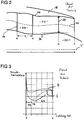
- FIG. 4 is an enlargement of the oval area N ' FIG. 1 shown.
- this oval cutout N was made FIG. 1 mirrored at the engine axis T.
- FIG. 4 a part of the outer housing 18 can be seen above and a part of the inner housing 20 can be seen below.
- the two housings 18 and 20 delimit the hot gas channel 22.
- a blade 32 of the Austrittsleitgitters 16 is arranged, which has a front edge E and a rear edge H.
- the axial profile length of the blade is s 0 .
- the hot gas channel 22 is radially outward (top in Fig. 4 ) by the outer wall 34 ', which is a part of the outer housing 18, and radially inward (bottom in Fig. 4 ) bounded by the inner wall 36 ', which forms part of the inner housing 20.
- the outer housing 18 also has an exit edge Z.
- the downstream end 35 'of the outer wall 34' is located on the annular exit edge Z (shown in the figures as a vertical line).
- a constriction 38' is arranged, which acts as a core flow nozzle.
- This constriction 38 ' is arranged closer to the trailing edge H than to the trailing edge Z, so that the axial distance between HQ' is smaller than the axial distance Q'Z.
- the radius R 1 of the inner wall 36 'in the vicinity of the absolute constriction Q' is locally larger than the radius the immediately adjacent regions of the inner wall 36 '.
- the radius R 2 of the outer wall 34 'in the vicinity of the absolute constriction Q' is locally smaller than the radius of the immediately adjacent portions of the outer wall 34 '.
- the radii R 1 and R 2 run in a plane perpendicular to the engine axis T.
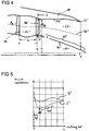
- the FIG. 5 shows the pressure distribution in the hot gas duct 22 at the axial height of the vane 32 from FIG. 4 , taking into account the flow delay of the duct and the profile of the vane 32.
- the delay from 43 'to the trailing edge H is less than in the FIG. 3 from point 43 to the trailing edge H, which also leads to lower losses.
- the upper curve D ' shows the pressure ratio at the pressure side of the vane 32
- the lower curve S' shows the pressure ratio at the suction side of the vane 32, measuring 50% of the channel height. This 50% channel height was shown as dashed curve 40 'in FIG FIG. 4 located.
- the curve 40 ' divides the hot runner 22 into an upper and a lower region in which 50% of the air mass flows in each case.
- FIG. 4 With a dashed curve 46 '(upper curve), the velocity of the flow along the inner wall 36' is determined FIG. 4 shown. Only the channel profile is considered. It can be seen that the speed at the leading edge E of the blade 32 is similar to that at the trailing edge H of the blade 32. Thus, the flow velocity, here in particular in the vicinity of the inner wall 36 ', hardly changed.
- FIG. 7 shows a section along the line AA in FIG. 4 ,
- a first embodiment with an inner wall 36 '" is shown in the upper half of Figure 7.
- the absolute bottlenecks 38'" are arranged on the inner wall 36 '"in the circumferential direction at the level of the respective guide vanes 32. Between the blades 32 are not absolute bottlenecks 38 '"provided.
- FIG. 7 2 In the lower left half of the FIG. 7 2 is a second embodiment having an inner wall 36 ", with the absolute bottlenecks 38" being circumferentially disposed between the respective vanes 56 and 58. There are no absolute bottlenecks 38 "at the level of the guide vanes 56 or 58.
- a free surface 48 is bounded radially inward by the inner wall 36".
- the free surface 48 is bounded radially outward by the outer wall 34 '.
- the free surface 48 In the circumferential direction, the free surface 48 is bounded by the two vanes 56 and 58.
- the free surface 48 is located in the direction perpendicular to the engine axis T plane. This level corresponds to the leaf level of the FIG. 7 ,
- a third embodiment is shown having an inner wall 36 'in which the absolute constriction 38' is rotationally symmetric and independent of the circumferential angle, ie, this constriction 38 'is disposed on the vanes 52 and 54 as well as between the vanes 52-56.
- a free surface 50 is bounded radially inwardly by the inner wall 36 '.
- the free surface 50 is bounded radially outward by the outer wall 34 '.
- the free surface 50 is bounded by the two vanes 54 and 56.
- the free surface 50 is located in the plane perpendicular to the engine axis T level. This level corresponds to the leaf level of the one pictured FIG. 7 ,
- the free area 48 of the second embodiment may be the same size as the free area 50 of the third embodiment.
Claims (7)
- Grille de guidage d'écoulement comportant une paroi extérieure (34') et une paroi intérieure (36') pour former un canal annulaire (22) et pour guider le courant de gaz chaud, et au moins une aube de guidage (32) disposée entre la paroi extérieure (34') et la paroi intérieure (36'),dans laquelle au moins un rétrécissement réduisant la section transversale (38') est disposé entre le bord avant (E) de l'aube de guidage (32) et l'extrémité aval (35') de la paroi extérieure (34'),dans laquelle au moins un rétrécissement absolu (38') est disposé dans la zone entre le bord avant (E) et l'extrémité aval (35') plus près du bord arrière (H) de l'aube de guidage (32) que de l'extrémité aval (35') de la paroi extérieure (34'),caractérisée en ce que, observé dans la direction axiale, le rétrécissement absolu (38') est disposé dans la direction d'écoulement, avant ou après, ou même directement sur le bord arrière (H) de l'aube de guidage (32), la distance axiale entre le rétrécissement absolu (38') et le bord arrière (H) étant au maximum de 30 % de la longueur axiale (S0) du profil de l'aube de guidage (32).
- Grille de guidage d'écoulement selon la revendication 1, caractérisée en ce que la paroi extérieure (34') à proximité du rétrécissement absolu (38') présente localement un rayon (R2) plus petit que dans les zones directement adjacentes axialement et/ou en ce que la paroi intérieure (36') à proximité du rétrécissement absolu (Q) présente localement un rayon (R1) plus grand que dans les zones directement adjacentes axialement.
- Grille de guidage d'écoulement selon au moins l'une des revendications précédentes, caractérisée en ce que, observé dans la direction circonférentielle, le rétrécissement absolu (38') est disposé au niveau des aubes de guidage (32) et/ou entre les aubes de guidage (32).
- Grille de guidage d'écoulement selon au moins l'une des revendications précédentes, caractérisée en ce que le rapport de surface entre la surface annulaire (Aq) au rétrécissement absolu (38') et la surface annulaire (AE) au bord avant (E) est inférieur à 75 %.
- Grille de guidage d'écoulement selon au moins l'une des revendications précédentes, caractérisée en ce que la distance axiale du rétrécissement absolu (38') du bord arrière (H) est au maximum de 20 % de la longueur axiale (S0) du profil de l'aube de guidage (32).
- Grille de guidage d'écoulement selon au moins l'une des revendications précédentes, caractérisée en ce que la distance axiale entre le rétrécissement absolu (38') et le bord arrière (H) est au maximum de 10 % de la longueur axiale (S0) du profil de l'aube de guidage (32).
- Turbosoufflante avec une grille de guidage d'écoulement selon au moins l'une des revendications précédentes, caractérisée en ce que la turbosoufflante (2) présente en particulier un taux de dilution égal au moins à 6.
Priority Applications (2)
| Application Number | Priority Date | Filing Date | Title |
|---|---|---|---|
| ES14197574T ES2743501T3 (es) | 2014-12-12 | 2014-12-12 | Rejilla guía de salida y turborreactor de doble flujo con una rejilla guía de salida |
| EP14197574.8A EP3032032B1 (fr) | 2014-12-12 | 2014-12-12 | Aubes directrices de sortie et turboréacteur à double flux avec des aubes directrices de sortie |
Applications Claiming Priority (1)
| Application Number | Priority Date | Filing Date | Title |
|---|---|---|---|
| EP14197574.8A EP3032032B1 (fr) | 2014-12-12 | 2014-12-12 | Aubes directrices de sortie et turboréacteur à double flux avec des aubes directrices de sortie |
Publications (2)
| Publication Number | Publication Date |
|---|---|
| EP3032032A1 EP3032032A1 (fr) | 2016-06-15 |
| EP3032032B1 true EP3032032B1 (fr) | 2019-06-12 |
Family
ID=52146113
Family Applications (1)
| Application Number | Title | Priority Date | Filing Date |
|---|---|---|---|
| EP14197574.8A Active EP3032032B1 (fr) | 2014-12-12 | 2014-12-12 | Aubes directrices de sortie et turboréacteur à double flux avec des aubes directrices de sortie |
Country Status (2)
| Country | Link |
|---|---|
| EP (1) | EP3032032B1 (fr) |
| ES (1) | ES2743501T3 (fr) |
Families Citing this family (5)
| Publication number | Priority date | Publication date | Assignee | Title |
|---|---|---|---|---|
| DE102015223210B3 (de) | 2015-11-24 | 2017-04-27 | MTU Aero Engines AG | Verdichter, Verfahren und Strömungsmaschine |
| PL239213B1 (pl) * | 2017-06-21 | 2021-11-15 | Panstwowa Wyzsza Szkola Zawodowa W Chelmie | Dysza wylotowa silnika turbowentylatorowego |
| DE102017222817A1 (de) | 2017-12-14 | 2019-06-19 | MTU Aero Engines AG | Turbinenmodul für eine strömungsmaschine |
| WO2019143366A1 (fr) * | 2018-01-22 | 2019-07-25 | Siemens Aktiengesellschaft | Diffuseur d'échappement pour un moteur de turbine à gaz |
| US10920599B2 (en) * | 2019-01-31 | 2021-02-16 | Raytheon Technologies Corporation | Contoured endwall for a gas turbine engine |
Family Cites Families (4)
| Publication number | Priority date | Publication date | Assignee | Title |
|---|---|---|---|---|
| US4023350A (en) * | 1975-11-10 | 1977-05-17 | United Technologies Corporation | Exhaust case for a turbine machine |
| US9732674B2 (en) * | 2010-12-24 | 2017-08-15 | Mitsubishi Hitachi Power Systems, Ltd. | Flow path structure and gas turbine exhaust diffuser |
| DE102011076804B4 (de) * | 2011-05-31 | 2019-04-25 | Honda Motor Co., Ltd. | Innenumfangsflächenform eines Lüftergehäuses eines Axialverdichters |
| EP2644846A1 (fr) * | 2012-03-30 | 2013-10-02 | Alstom Technology Ltd | Diffuseur d'échappement d'une turbine à gaz |
-
2014
- 2014-12-12 ES ES14197574T patent/ES2743501T3/es active Active
- 2014-12-12 EP EP14197574.8A patent/EP3032032B1/fr active Active
Non-Patent Citations (1)
| Title |
|---|
| None * |
Also Published As
| Publication number | Publication date |
|---|---|
| ES2743501T3 (es) | 2020-02-19 |
| EP3032032A1 (fr) | 2016-06-15 |
Similar Documents
| Publication | Publication Date | Title |
|---|---|---|
| EP3032032B1 (fr) | Aubes directrices de sortie et turboréacteur à double flux avec des aubes directrices de sortie | |
| EP2824284B1 (fr) | Turbine à double flux | |
| DE60211061T2 (de) | Axialturbine mit einer Stufe in einem Abströmkanal | |
| DE60124572T2 (de) | Halbaxial- und kreiselverdichter für ein gasturbinentriebwerk | |
| DE102015219556A1 (de) | Diffusor für Radialverdichter, Radialverdichter und Turbomaschine mit Radialverdichter | |
| EP2362065B1 (fr) | Canal de dérivation avec couronne d'aubes statoriques dans un turboréacteur avec soufflante | |
| EP1789653B1 (fr) | Rotor pour un propulseur | |
| DE112007002564T5 (de) | Diffusor und Auslasssystem für Turbine | |
| EP3009683B1 (fr) | Systeme et procede pour prélèvement d'air de compresseur d'un propulseur | |
| CH701954B1 (de) | Grundkörper eines Abgasdiffusors für ein Gasturbinensystem. | |
| EP2835522B2 (fr) | Dispositif et procédé de soufflage d'air comprimé dans une turbine | |
| EP2881548B1 (fr) | Compresseur de turbine à gaz | |
| DE10037684A1 (de) | Niederdruckdampfturbine mit Mehrkanal-Diffusor | |
| EP1632648B1 (fr) | Turbine à gaz comprenant un conduit de transition | |
| EP2846000A2 (fr) | Roue statorique d'une turbine à gaz | |
| DE102013202786B4 (de) | Vorrichtung zum Abblasen von Verdichterluft in einem Turbofantriebwerk | |
| DE102019120816B3 (de) | Verdichterlaufrad mit geteilten Hauptschaufeln | |
| EP3568597A1 (fr) | Étage de retour et turbomachine à énergie fluidique radiale | |
| EP3495639B1 (fr) | Module de compresseur pour une turbomachine réduisant la couche limite dans un carter intermédiaire de compresseur | |
| DE102016203305A1 (de) | Rückführstufe, Radialturbofluidenergiemaschine | |
| DE102010044819B4 (de) | Axialturbine und ein Verfahren zum Abführen eines Stroms von einer Axialturbine | |
| DE10255389A1 (de) | Niederdruckdampfturbine mit Mehrkanal-Diffusor | |
| EP3483391B1 (fr) | Pale de turbine d'une couronne de pale de turbine | |
| WO2016184548A1 (fr) | Aube directrice pour un diffuseur d'un compresseur centrifuge | |
| EP3173629B1 (fr) | Procédures pour et compresseur de turbomachine |
Legal Events
| Date | Code | Title | Description |
|---|---|---|---|
| PUAI | Public reference made under article 153(3) epc to a published international application that has entered the european phase |
Free format text: ORIGINAL CODE: 0009012 |
|
| AK | Designated contracting states |
Kind code of ref document: A1 Designated state(s): AL AT BE BG CH CY CZ DE DK EE ES FI FR GB GR HR HU IE IS IT LI LT LU LV MC MK MT NL NO PL PT RO RS SE SI SK SM TR |
|
| AX | Request for extension of the european patent |
Extension state: BA ME |
|
| STAA | Information on the status of an ep patent application or granted ep patent |
Free format text: STATUS: REQUEST FOR EXAMINATION WAS MADE |
|
| 17P | Request for examination filed |
Effective date: 20161114 |
|
| RBV | Designated contracting states (corrected) |
Designated state(s): AL AT BE BG CH CY CZ DE DK EE ES FI FR GB GR HR HU IE IS IT LI LT LU LV MC MK MT NL NO PL PT RO RS SE SI SK SM TR |
|
| GRAP | Despatch of communication of intention to grant a patent |
Free format text: ORIGINAL CODE: EPIDOSNIGR1 |
|
| STAA | Information on the status of an ep patent application or granted ep patent |
Free format text: STATUS: GRANT OF PATENT IS INTENDED |
|
| INTG | Intention to grant announced |
Effective date: 20190104 |
|
| GRAS | Grant fee paid |
Free format text: ORIGINAL CODE: EPIDOSNIGR3 |
|
| GRAA | (expected) grant |
Free format text: ORIGINAL CODE: 0009210 |
|
| STAA | Information on the status of an ep patent application or granted ep patent |
Free format text: STATUS: THE PATENT HAS BEEN GRANTED |
|
| AK | Designated contracting states |
Kind code of ref document: B1 Designated state(s): AL AT BE BG CH CY CZ DE DK EE ES FI FR GB GR HR HU IE IS IT LI LT LU LV MC MK MT NL NO PL PT RO RS SE SI SK SM TR |
|
| REG | Reference to a national code |
Ref country code: GB Ref legal event code: FG4D Free format text: NOT ENGLISH |
|
| REG | Reference to a national code |
Ref country code: CH Ref legal event code: EP |
|
| REG | Reference to a national code |
Ref country code: AT Ref legal event code: REF Ref document number: 1142777 Country of ref document: AT Kind code of ref document: T Effective date: 20190615 |
|
| REG | Reference to a national code |
Ref country code: DE Ref legal event code: R096 Ref document number: 502014011911 Country of ref document: DE |
|
| REG | Reference to a national code |
Ref country code: IE Ref legal event code: FG4D Free format text: LANGUAGE OF EP DOCUMENT: GERMAN |
|
| REG | Reference to a national code |
Ref country code: NL Ref legal event code: MP Effective date: 20190612 |
|
| REG | Reference to a national code |
Ref country code: LT Ref legal event code: MG4D |
|
| PG25 | Lapsed in a contracting state [announced via postgrant information from national office to epo] |
Ref country code: AL Free format text: LAPSE BECAUSE OF FAILURE TO SUBMIT A TRANSLATION OF THE DESCRIPTION OR TO PAY THE FEE WITHIN THE PRESCRIBED TIME-LIMIT Effective date: 20190612 Ref country code: FI Free format text: LAPSE BECAUSE OF FAILURE TO SUBMIT A TRANSLATION OF THE DESCRIPTION OR TO PAY THE FEE WITHIN THE PRESCRIBED TIME-LIMIT Effective date: 20190612 Ref country code: LT Free format text: LAPSE BECAUSE OF FAILURE TO SUBMIT A TRANSLATION OF THE DESCRIPTION OR TO PAY THE FEE WITHIN THE PRESCRIBED TIME-LIMIT Effective date: 20190612 Ref country code: HR Free format text: LAPSE BECAUSE OF FAILURE TO SUBMIT A TRANSLATION OF THE DESCRIPTION OR TO PAY THE FEE WITHIN THE PRESCRIBED TIME-LIMIT Effective date: 20190612 Ref country code: NO Free format text: LAPSE BECAUSE OF FAILURE TO SUBMIT A TRANSLATION OF THE DESCRIPTION OR TO PAY THE FEE WITHIN THE PRESCRIBED TIME-LIMIT Effective date: 20190912 Ref country code: SE Free format text: LAPSE BECAUSE OF FAILURE TO SUBMIT A TRANSLATION OF THE DESCRIPTION OR TO PAY THE FEE WITHIN THE PRESCRIBED TIME-LIMIT Effective date: 20190612 |
|
| PG25 | Lapsed in a contracting state [announced via postgrant information from national office to epo] |
Ref country code: LV Free format text: LAPSE BECAUSE OF FAILURE TO SUBMIT A TRANSLATION OF THE DESCRIPTION OR TO PAY THE FEE WITHIN THE PRESCRIBED TIME-LIMIT Effective date: 20190612 Ref country code: RS Free format text: LAPSE BECAUSE OF FAILURE TO SUBMIT A TRANSLATION OF THE DESCRIPTION OR TO PAY THE FEE WITHIN THE PRESCRIBED TIME-LIMIT Effective date: 20190612 Ref country code: BG Free format text: LAPSE BECAUSE OF FAILURE TO SUBMIT A TRANSLATION OF THE DESCRIPTION OR TO PAY THE FEE WITHIN THE PRESCRIBED TIME-LIMIT Effective date: 20190912 Ref country code: GR Free format text: LAPSE BECAUSE OF FAILURE TO SUBMIT A TRANSLATION OF THE DESCRIPTION OR TO PAY THE FEE WITHIN THE PRESCRIBED TIME-LIMIT Effective date: 20190913 |
|
| PG25 | Lapsed in a contracting state [announced via postgrant information from national office to epo] |
Ref country code: PT Free format text: LAPSE BECAUSE OF FAILURE TO SUBMIT A TRANSLATION OF THE DESCRIPTION OR TO PAY THE FEE WITHIN THE PRESCRIBED TIME-LIMIT Effective date: 20191014 Ref country code: RO Free format text: LAPSE BECAUSE OF FAILURE TO SUBMIT A TRANSLATION OF THE DESCRIPTION OR TO PAY THE FEE WITHIN THE PRESCRIBED TIME-LIMIT Effective date: 20190612 Ref country code: NL Free format text: LAPSE BECAUSE OF FAILURE TO SUBMIT A TRANSLATION OF THE DESCRIPTION OR TO PAY THE FEE WITHIN THE PRESCRIBED TIME-LIMIT Effective date: 20190612 Ref country code: CZ Free format text: LAPSE BECAUSE OF FAILURE TO SUBMIT A TRANSLATION OF THE DESCRIPTION OR TO PAY THE FEE WITHIN THE PRESCRIBED TIME-LIMIT Effective date: 20190612 Ref country code: EE Free format text: LAPSE BECAUSE OF FAILURE TO SUBMIT A TRANSLATION OF THE DESCRIPTION OR TO PAY THE FEE WITHIN THE PRESCRIBED TIME-LIMIT Effective date: 20190612 Ref country code: SK Free format text: LAPSE BECAUSE OF FAILURE TO SUBMIT A TRANSLATION OF THE DESCRIPTION OR TO PAY THE FEE WITHIN THE PRESCRIBED TIME-LIMIT Effective date: 20190612 |
|
| REG | Reference to a national code |
Ref country code: ES Ref legal event code: FG2A Ref document number: 2743501 Country of ref document: ES Kind code of ref document: T3 Effective date: 20200219 |
|
| PG25 | Lapsed in a contracting state [announced via postgrant information from national office to epo] |
Ref country code: IT Free format text: LAPSE BECAUSE OF FAILURE TO SUBMIT A TRANSLATION OF THE DESCRIPTION OR TO PAY THE FEE WITHIN THE PRESCRIBED TIME-LIMIT Effective date: 20190612 Ref country code: IS Free format text: LAPSE BECAUSE OF FAILURE TO SUBMIT A TRANSLATION OF THE DESCRIPTION OR TO PAY THE FEE WITHIN THE PRESCRIBED TIME-LIMIT Effective date: 20191012 Ref country code: SM Free format text: LAPSE BECAUSE OF FAILURE TO SUBMIT A TRANSLATION OF THE DESCRIPTION OR TO PAY THE FEE WITHIN THE PRESCRIBED TIME-LIMIT Effective date: 20190612 |
|
| REG | Reference to a national code |
Ref country code: DE Ref legal event code: R097 Ref document number: 502014011911 Country of ref document: DE |
|
| PG25 | Lapsed in a contracting state [announced via postgrant information from national office to epo] |
Ref country code: TR Free format text: LAPSE BECAUSE OF FAILURE TO SUBMIT A TRANSLATION OF THE DESCRIPTION OR TO PAY THE FEE WITHIN THE PRESCRIBED TIME-LIMIT Effective date: 20190612 |
|
| PLBE | No opposition filed within time limit |
Free format text: ORIGINAL CODE: 0009261 |
|
| STAA | Information on the status of an ep patent application or granted ep patent |
Free format text: STATUS: NO OPPOSITION FILED WITHIN TIME LIMIT |
|
| PG25 | Lapsed in a contracting state [announced via postgrant information from national office to epo] |
Ref country code: DK Free format text: LAPSE BECAUSE OF FAILURE TO SUBMIT A TRANSLATION OF THE DESCRIPTION OR TO PAY THE FEE WITHIN THE PRESCRIBED TIME-LIMIT Effective date: 20190612 Ref country code: PL Free format text: LAPSE BECAUSE OF FAILURE TO SUBMIT A TRANSLATION OF THE DESCRIPTION OR TO PAY THE FEE WITHIN THE PRESCRIBED TIME-LIMIT Effective date: 20190612 |
|
| 26N | No opposition filed |
Effective date: 20200313 |
|
| PG25 | Lapsed in a contracting state [announced via postgrant information from national office to epo] |
Ref country code: IS Free format text: LAPSE BECAUSE OF FAILURE TO SUBMIT A TRANSLATION OF THE DESCRIPTION OR TO PAY THE FEE WITHIN THE PRESCRIBED TIME-LIMIT Effective date: 20200224 Ref country code: SI Free format text: LAPSE BECAUSE OF FAILURE TO SUBMIT A TRANSLATION OF THE DESCRIPTION OR TO PAY THE FEE WITHIN THE PRESCRIBED TIME-LIMIT Effective date: 20190612 |
|
| PG2D | Information on lapse in contracting state deleted |
Ref country code: IS |
|
| REG | Reference to a national code |
Ref country code: CH Ref legal event code: PL |
|
| REG | Reference to a national code |
Ref country code: BE Ref legal event code: MM Effective date: 20191231 |
|
| PG25 | Lapsed in a contracting state [announced via postgrant information from national office to epo] |
Ref country code: MC Free format text: LAPSE BECAUSE OF FAILURE TO SUBMIT A TRANSLATION OF THE DESCRIPTION OR TO PAY THE FEE WITHIN THE PRESCRIBED TIME-LIMIT Effective date: 20190612 |
|
| PG25 | Lapsed in a contracting state [announced via postgrant information from national office to epo] |
Ref country code: LU Free format text: LAPSE BECAUSE OF NON-PAYMENT OF DUE FEES Effective date: 20191212 Ref country code: IE Free format text: LAPSE BECAUSE OF NON-PAYMENT OF DUE FEES Effective date: 20191212 |
|
| PG25 | Lapsed in a contracting state [announced via postgrant information from national office to epo] |
Ref country code: CH Free format text: LAPSE BECAUSE OF NON-PAYMENT OF DUE FEES Effective date: 20191231 Ref country code: LI Free format text: LAPSE BECAUSE OF NON-PAYMENT OF DUE FEES Effective date: 20191231 Ref country code: BE Free format text: LAPSE BECAUSE OF NON-PAYMENT OF DUE FEES Effective date: 20191231 |
|
| REG | Reference to a national code |
Ref country code: AT Ref legal event code: MM01 Ref document number: 1142777 Country of ref document: AT Kind code of ref document: T Effective date: 20191212 |
|
| PG25 | Lapsed in a contracting state [announced via postgrant information from national office to epo] |
Ref country code: AT Free format text: LAPSE BECAUSE OF NON-PAYMENT OF DUE FEES Effective date: 20191212 Ref country code: CY Free format text: LAPSE BECAUSE OF FAILURE TO SUBMIT A TRANSLATION OF THE DESCRIPTION OR TO PAY THE FEE WITHIN THE PRESCRIBED TIME-LIMIT Effective date: 20190612 |
|
| PG25 | Lapsed in a contracting state [announced via postgrant information from national office to epo] |
Ref country code: HU Free format text: LAPSE BECAUSE OF FAILURE TO SUBMIT A TRANSLATION OF THE DESCRIPTION OR TO PAY THE FEE WITHIN THE PRESCRIBED TIME-LIMIT; INVALID AB INITIO Effective date: 20141212 Ref country code: MT Free format text: LAPSE BECAUSE OF FAILURE TO SUBMIT A TRANSLATION OF THE DESCRIPTION OR TO PAY THE FEE WITHIN THE PRESCRIBED TIME-LIMIT Effective date: 20190612 |
|
| PG25 | Lapsed in a contracting state [announced via postgrant information from national office to epo] |
Ref country code: MK Free format text: LAPSE BECAUSE OF FAILURE TO SUBMIT A TRANSLATION OF THE DESCRIPTION OR TO PAY THE FEE WITHIN THE PRESCRIBED TIME-LIMIT Effective date: 20190612 |
|
| PGFP | Annual fee paid to national office [announced via postgrant information from national office to epo] |
Ref country code: ES Payment date: 20230119 Year of fee payment: 9 |
|
| PGFP | Annual fee paid to national office [announced via postgrant information from national office to epo] |
Ref country code: GB Payment date: 20231220 Year of fee payment: 10 |
|
| PGFP | Annual fee paid to national office [announced via postgrant information from national office to epo] |
Ref country code: FR Payment date: 20231219 Year of fee payment: 10 Ref country code: DE Payment date: 20231214 Year of fee payment: 10 |
|
| PGFP | Annual fee paid to national office [announced via postgrant information from national office to epo] |
Ref country code: ES Payment date: 20240118 Year of fee payment: 10 |