EP2881548A1 - Gas turbine compressor - Google Patents
Gas turbine compressor Download PDFInfo
- Publication number
- EP2881548A1 EP2881548A1 EP13196267.2A EP13196267A EP2881548A1 EP 2881548 A1 EP2881548 A1 EP 2881548A1 EP 13196267 A EP13196267 A EP 13196267A EP 2881548 A1 EP2881548 A1 EP 2881548A1
- Authority
- EP
- European Patent Office
- Prior art keywords
- gas turbine
- inlet opening
- turbine according
- dispensing channel
- turntable
- Prior art date
- Legal status (The legal status is an assumption and is not a legal conclusion. Google has not performed a legal analysis and makes no representation as to the accuracy of the status listed.)
- Granted
Links
- 230000004323 axial length Effects 0.000 claims description 6
- 238000010079 rubber tapping Methods 0.000 claims 1
- 239000012530 fluid Substances 0.000 description 3
- 239000011248 coating agent Substances 0.000 description 2
- 238000000576 coating method Methods 0.000 description 2
- 238000005299 abrasion Methods 0.000 description 1
- 125000004122 cyclic group Chemical group 0.000 description 1
- 238000005553 drilling Methods 0.000 description 1
- 238000007789 sealing Methods 0.000 description 1
- 238000004904 shortening Methods 0.000 description 1
- 230000007704 transition Effects 0.000 description 1
Images


Classifications
-
- F—MECHANICAL ENGINEERING; LIGHTING; HEATING; WEAPONS; BLASTING
- F02—COMBUSTION ENGINES; HOT-GAS OR COMBUSTION-PRODUCT ENGINE PLANTS
- F02C—GAS-TURBINE PLANTS; AIR INTAKES FOR JET-PROPULSION PLANTS; CONTROLLING FUEL SUPPLY IN AIR-BREATHING JET-PROPULSION PLANTS
- F02C6/00—Plural gas-turbine plants; Combinations of gas-turbine plants with other apparatus; Adaptations of gas- turbine plants for special use
- F02C6/04—Gas-turbine plants providing heated or pressurised working fluid for other apparatus, e.g. without mechanical power output
- F02C6/06—Gas-turbine plants providing heated or pressurised working fluid for other apparatus, e.g. without mechanical power output providing compressed gas
- F02C6/08—Gas-turbine plants providing heated or pressurised working fluid for other apparatus, e.g. without mechanical power output providing compressed gas the gas being bled from the gas-turbine compressor
-
- F—MECHANICAL ENGINEERING; LIGHTING; HEATING; WEAPONS; BLASTING
- F01—MACHINES OR ENGINES IN GENERAL; ENGINE PLANTS IN GENERAL; STEAM ENGINES
- F01D—NON-POSITIVE DISPLACEMENT MACHINES OR ENGINES, e.g. STEAM TURBINES
- F01D17/00—Regulating or controlling by varying flow
- F01D17/10—Final actuators
- F01D17/12—Final actuators arranged in stator parts
- F01D17/14—Final actuators arranged in stator parts varying effective cross-sectional area of nozzles or guide conduits
- F01D17/16—Final actuators arranged in stator parts varying effective cross-sectional area of nozzles or guide conduits by means of nozzle vanes
- F01D17/162—Final actuators arranged in stator parts varying effective cross-sectional area of nozzles or guide conduits by means of nozzle vanes for axial flow, i.e. the vanes turning around axes which are essentially perpendicular to the rotor centre line
-
- F—MECHANICAL ENGINEERING; LIGHTING; HEATING; WEAPONS; BLASTING
- F02—COMBUSTION ENGINES; HOT-GAS OR COMBUSTION-PRODUCT ENGINE PLANTS
- F02C—GAS-TURBINE PLANTS; AIR INTAKES FOR JET-PROPULSION PLANTS; CONTROLLING FUEL SUPPLY IN AIR-BREATHING JET-PROPULSION PLANTS
- F02C9/00—Controlling gas-turbine plants; Controlling fuel supply in air- breathing jet-propulsion plants
- F02C9/16—Control of working fluid flow
- F02C9/18—Control of working fluid flow by bleeding, bypassing or acting on variable working fluid interconnections between turbines or compressors or their stages
-
- F—MECHANICAL ENGINEERING; LIGHTING; HEATING; WEAPONS; BLASTING
- F04—POSITIVE - DISPLACEMENT MACHINES FOR LIQUIDS; PUMPS FOR LIQUIDS OR ELASTIC FLUIDS
- F04D—NON-POSITIVE-DISPLACEMENT PUMPS
- F04D29/00—Details, component parts, or accessories
- F04D29/40—Casings; Connections of working fluid
- F04D29/52—Casings; Connections of working fluid for axial pumps
- F04D29/54—Fluid-guiding means, e.g. diffusers
- F04D29/541—Specially adapted for elastic fluid pumps
- F04D29/545—Ducts
-
- F—MECHANICAL ENGINEERING; LIGHTING; HEATING; WEAPONS; BLASTING
- F04—POSITIVE - DISPLACEMENT MACHINES FOR LIQUIDS; PUMPS FOR LIQUIDS OR ELASTIC FLUIDS
- F04D—NON-POSITIVE-DISPLACEMENT PUMPS
- F04D29/00—Details, component parts, or accessories
- F04D29/40—Casings; Connections of working fluid
- F04D29/52—Casings; Connections of working fluid for axial pumps
- F04D29/54—Fluid-guiding means, e.g. diffusers
- F04D29/56—Fluid-guiding means, e.g. diffusers adjustable
- F04D29/563—Fluid-guiding means, e.g. diffusers adjustable specially adapted for elastic fluid pumps
-
- Y—GENERAL TAGGING OF NEW TECHNOLOGICAL DEVELOPMENTS; GENERAL TAGGING OF CROSS-SECTIONAL TECHNOLOGIES SPANNING OVER SEVERAL SECTIONS OF THE IPC; TECHNICAL SUBJECTS COVERED BY FORMER USPC CROSS-REFERENCE ART COLLECTIONS [XRACs] AND DIGESTS
- Y02—TECHNOLOGIES OR APPLICATIONS FOR MITIGATION OR ADAPTATION AGAINST CLIMATE CHANGE
- Y02T—CLIMATE CHANGE MITIGATION TECHNOLOGIES RELATED TO TRANSPORTATION
- Y02T50/00—Aeronautics or air transport
- Y02T50/60—Efficient propulsion technologies, e.g. for aircraft
Definitions
- the invention relates to a gas turbine according to the preamble of claim 1.
- FIG. 1 shows a sectional view of a gas turbine of the outer gas path.
- the gas turbine has a housing 1 with a bore 2 and a nozzle channel 3. This substantially horizontally extending housing 1 separates the lower region (main gas path 10) from the upper region (secondary gas path 12).
- the working fluid here gas
- a Verstellleitschaufel 4 has a pivot 5, a turntable 6 and a stator blade 7.
- the pivot pin 5 is arranged in the bore 2 and is held by a guide bush 8 arranged in the bore 2. Between the bore 2 and the turntable 6, a sealing ring 9 is attached.
- the vane blade 7 has a leading edge 14 and a trailing edge 16 of the prior art.
- the leading edge 14 usually does not protrude beyond the turntable 6.
- the trailing edge 16 projects over the turntable 6, so that a short flag 18 is formed.
- the point where the flag 18 and the trailing edge meet 16 is referred to as flag edge 20.
- an inlet opening 22 of the dispensing channel 3 is arranged after this known trailing edge 16 of the guide blade 7. This means that in the prior art, the beginning 24 of the inlet opening 22 is disposed behind the flag edge 20. It is irrelevant whether the overhang over the turntable 6 is small or whether the beginning 24 of the inlet opening 22 is arranged in the flow direction further down.
- a first outer surface 30 of the annular space Before the bore 2, a first outer surface 30 of the annular space can be seen.
- the first outer surface 30 is in a first radius r 1 to the main shaft 60 (see FIG. 3 ) of the gas turbine arranged.
- a second outer surface 32 Between the bore 2 and the inlet opening 22 of the dispensing channel 3, a second outer surface 32 can be seen.
- a third outer surface 34 of the annular space is seen, which is usually arranged in alignment with the second outer surface 32 (indicated by the connecting line V).
- these three outer surfaces have a continuous transition, ie the annular space is usually cylindrical or conical at these locations.
- Such bleed channels 3 serve to guide fluid out of the main gas path 10 into the secondary gas path 12. It must be ensured that the sufficient fluid with a sufficient Pressure is passed through the tap channel 3.
- the guide vanes must have a corresponding minimum length in order to effect a sufficient deflection of the air through the Verstellleitschaufel.
- the inlet openings of the dispensing channels must be arranged correspondingly further to the rear. This leads to the fact that the gas turbine has a great length and thus becomes heavier.
- the inlet openings of the dispensing channels can be designed only for one operating point of the gas turbine.
- the present invention is based on the object of making the gas turbine shorter and lighter than is known from the prior art.
- the invention relates to a gas turbine, in particular an aircraft gas turbine.
- This gas turbine comprises at least one housing having at least one bleed passage and at least one bore, and at least one Verstellleitschaufel having a pivot, a turntable and a vane blade.
- the pivot is located in the bore and the vane blade is formed on the turntable.
- the integrally formed on the turntable vane blade protrudes over this turntable, that facing the tap channel, and / or in particular virtual, flag edge of the vane blade viewed in the flow direction of the gas path of the gas turbine behind or after the beginning of the inlet opening of the dispensing channel is arranged.
- the flag edge can also be rounded. Other shapes are also conceivable.
- a so-called virtual flag edge can be arranged after the beginning of the inlet opening of the dispensing channel.
- the point of intersection between a first tangent that passes through the flag and a second tangent that passes through the trailing edge of the airfoil forms the virtual flag edge, which faces in particular to the tap channel.
- not shown flag edge is not relevant to the present invention. This not shown flag edge is thus facing away from the tap channel.
- the length of the gas turbine can be shortened without having to change the flag length of Verstellleitschaufeln. The shortening makes the gas turbine lighter.
- the bore is arranged in the flow direction of the gas path of the gas turbine viewed in front of the tap channel. This ensures that the Verstellleitschaufel can be flowed substantially free of turbulence.
- the first circumferential angle between a vertical and the bore is equal to the second circumferential angle between the vertical and the inlet opening of the dispensing channel.
- this wave is perpendicular to the viewing plane (see FIG. 3 ).
- the listed in the claims perpendicular from the outer surface of the annular space at the 12 o'clock position passes through the main shaft of the gas turbine.
- the inlet port is also at the 1 o'clock position since both assume the same circumferential angle with this perpendicular.
- the outer surface of the annular space between the bore and the inlet opening of the dispensing channel has a different radius than the outer surface of the annular space after the inlet opening of the dispensing channel.
- the pressure conditions in the tap channel can be optimally designed.
- the outer surface of the annular space between the bore and the inlet opening is hereinafter referred to in short form as the second outer surface.
- the outer surface of the annular space after the inlet opening is hereinafter referred to in short form as the third outer surface.
- the outer surface of the annular space between the bore and the inlet opening of the dispensing channel has a larger radius than a lip arranged after the inlet opening of the dispensing channel.
- the lip extends the end of the inlet opening radially in such a way that the dispensing channel preferably protrudes radially inwards, thereby overlapping the upper area of the guide blade in the radial direction. This can be used to ensure that the air in the upper part of the gas path along the Verstellleitschaufel along and pressed to the lip in the tap channel is pressed to lead some air from the main gas path in the Maugaspfad.
- a first axial distance D is present between the beginning and the trailing edge.
- B represents the axial length of the flag, wherein the ratio D / B between 0.25 and 0.90, preferably between 0.35 and 0.55, is. This indicates which axial portion of the flag is arranged below the inlet opening.
- a first distance D is present between the beginning and the trailing edge.
- a second axial distance C exists between the beginning and one end of the inlet opening, the ratio D / C being between 0.15 and 0.45, preferably between 0.25 and 0.35. This indicates which axial portion of the inlet opening is covered with the flag.
- the lip is radially displaceable.
- the displaceability of the lip serves to be able to adapt the dispensing pressure at the dispensing opening to the operating points of the gas turbine.
- the lip can be moved, for example, via an active gap control (commonly known as ACC - active clearance control).
- the flag edge of the guide blade is viewed in the flow direction of the gas path of the gas turbine arranged after the beginning of the inlet opening of the dispensing channel when the opening angle ⁇ of the Verstellleitschaufel is between 0 ° and 60 °, in particular between 15 ° and 45 °.
- Another advantageous range for the opening angle ⁇ is between 20 ° and 35 °.
- the flag gap is the distance between the second outer surface and the flag. Furthermore, the flag corner even have a larger radius than the second outer surface, so that the flag edge protrudes into the tap channel.
- the inlet opening is circular, square, rectangular or a circumferential groove.
- the dispensing channel can be cylindrical, conical or cuboidal.
- the corners of the inlet openings may be rounded.
- a further advantageous embodiment of the invention form a plurality of Verstellleitschaufeln a vane ring, wherein two Verstellleitschaufeln have a different angular distance than two other Verstellleitschaufeln within the guide vane ring.
- Such an arrangement is called cyclic spacing.
- FIG. 2 a longitudinal section through the upper portion of a gas turbine according to an embodiment of the invention is shown.
- the embodiment of the guide blade according to the invention 7 have another trailing edge 46, so that the inventive flag 48 may be longer than the known from the prior art flag 18.
- the flag 48 according to the invention and the trailing edge 46 according to the invention meet in the flag corner 50 according to the invention.
- the flag corner 50 'can also be rounded. Other shapes are also conceivable.
- the so-called virtual flag edge 50 " should be arranged after the beginning 24 of the inlet opening 22 of the dispensing channel 3.
- flag edge 50 and the rounded flag edge 50 ' have the same virtual flag edge 50 ".
- the flag edge 50 (or 50 ") according to the invention is offset by a certain distance A (or A ') behind the beginning 24 of the inlet opening 22, so that a part of the flag 48 is overlapped by the inlet opening 22 Beginning 24, the point of intersection resulting from the second outer surface 32 and the front boundary 47 of the dispensing channel 3.
- A or A '
- a first axial distance D is plotted, which represents the axial length between the beginning 24 and the trailing edge 46.
- the second axial distance C is shown, which represents the axial length between the beginning 24 and the end 52 of the inlet opening 22.
- the front boundary 47 can assume a first opening angle ⁇ 1 of 30 ° to 60 ° relative to the engine axis 60 or an axis P 1 parallel thereto.
- ⁇ 1 the angle between the straight line P 1 and the dashed line at the front boundary 47 tangent T x is meant.
- the first opening angle is ⁇ 1 ⁇ 35 °.
- a downstream rear boundary 49 of the dispensing channel 3 opens into the end 52 of the inlet opening 22 and can assume a second opening angle ⁇ 2 of 30 ° to 60 ° relative to the engine axis 60 or an axis P 2 parallel thereto.
- the angle ⁇ 2 between the line P 2 and the dashed lines at the rear boundary 49 drawn tangent T y meant.
- the adjusting vane 5 in FIG. 1 for the best representability the smallest opening angle ⁇ of 0 ° occupies.
- the Verstellleitschaufeln 4 and 4 ' typically occupy only an opening angle ⁇ of at least 6 °, d. h the adjusting vane is always adjusted to the flow.
- a part of the trailing edge 46 or the entire trailing edge 46 may be arranged behind or behind the beginning 24 of the inlet opening 22.
- the end 52 of the inlet opening 22 according to the invention is designed differently than the end 26 according to the prior art.
- the end 52 according to the invention can be arranged radially offset inwards relative to the known end 26 by the distance ⁇ r and forms the lip 54.
- a third outer surface 55 follows, in which an abradable coating 56 is arranged.
- the outer surface 55 is arranged in a second radius r 2 to the main shaft 60.
- a blade 58 can be seen.
- the lip 54 may be radially displaceable.
- the vane blade 7 is designed in the outer region of the annular space in combination with the tap channel 3, the shape and the radial position of the lip 54 such that the required delivery pressure in the tap channel 3 is ensured.
- FIG. 3 a cross-section through a gas turbine is shown, with only two Verstellleitschaufeln 4 and 4 'and two Zapfkanäle 3 and 3' are shown by way of example.
- the gas is guided from the front through the leaf level.
- the outer housing 1 with the Verstellleitschaufel 4 including pivot 5, turntable 6 and vane blade 7 is shown.
- the outer housing 1 has a first radius r 1 .
- the adjustment vanes 4 and 4 ' are framed by the inner housing 63, so that between the outer housing 1 and the inner housing 63, a Leitschaufelring 59 forms here with two Verstellleitschaufeln 4 and 4'.
- a vertically extending vertical 62 is located.
- the axis of rotation 64 and the vertical 62 form an angle ⁇ (here 15 °). This corresponds with a clock the 1 o'clock position.
- the Lips 54 radially inwardly and thereby covers the upper part of the vane blade 7.
- the lip 54 has a second radius r 2 .
- the first radius r 1 is greater than the second radius r 2 .
- the tap channel 3 has been designed by way of example rectangular.
- the axis of rotation 66 of the second Verstellleitschaufel 4 'and the vertical 62 here form an angle of 45 °.
- the angular distance ⁇ indicates the angle between the axis of rotation 64 and the axis of rotation 66. This angular distance ⁇ is 30 ° here.
- the angular distances between all axes of rotation can be the same. In a preferred embodiment, the angular distances may become continuously smaller.
- the first angular distances in a segment of a vane ring 59 are identical.
- the second angular distances are also identical, but the first angular distances are different from the second angular distances.
- the vane ring 59 may be divided into two, three or four (even more) preferably equal segments.
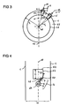
- FIG. 4 is a plan view of the gas turbine along the axis of rotation 64 of the Verstellleitschaufel 4 shown.
- the gas flows from bottom to top.
- Left and right outside the here vertically extending main gas path 10 is limited by the housing 1.
- the main shaft 60 of the gas turbine runs vertically.
- an inlet opening 22 to the dispensing channel 3 (not shown here, for example, rectangular) can be seen.
- the lower edge of the rectangle here forms the beginning 24 of the inlet opening 22 and the upper edge of the rectangle forms the end 52 according to the invention of the inlet opening 22.
- Below the inlet opening 22 is the Verstellleitschaufel 4 with a pivot 5, a turntable 6 and a molded thereon vane blade.
- the inventive flag 48 protrudes beyond the turntable 6 addition.
- the flag edge 50 or 50 "according to the invention is located below the inlet opening 22.
- the guide blade 7 is rotatably mounted about the rotation axis 64.
- the guide blade 7 and the main shaft 60 enclose an opening angle ⁇ .
- the vane blade 7 (or its chord) is arranged in this illustration on the main shaft 60, then the adjusting vane has an opening angle ⁇ of 0 °.
- such Verstellleitschaufeln 4 and the corresponding Zapfkanäle 3 are arranged in the high-pressure compressor of a gas turbine.
Abstract
Die Erfindung betrifft eine Gasturbine, insbesondere eine Fluggasturbine. Diese Gasturbine umfasst mindestens ein Gehäuse (1), das mindestens einen Zapfkanal (3) und mindestens eine Bohrung (2) aufweist, und mindestens eine Verstellleitschaufel (4), die einen Drehzapfen (5), einen Drehteller (6) und ein Leitschaufelblatt (7) aufweist. Der Drehzapfen (5) ist in der Bohrung (2) angeordnet und das Leitschaufelblatt (7) ist am Drehteller (6) angeformt. Das an dem Drehteller (6) angeformte Leitschaufelblatt (7) ragt derart über diesen Drehteller (6), dass ein zum Zapfkanal (3) zugewandtes, und/oder insbesondere virtuelles, Fahneneck (50, 50") des Leitschaufelblattes (7) in Strömungsrichtung des Gaspfades der Gasturbine betrachtet nach dem Anfang (24) der Einlassöffnung (22) des Zapfkanals (3) angeordnet ist.The invention relates to a gas turbine, in particular an aircraft gas turbine. This gas turbine comprises at least one housing (1) which has at least one dispensing channel (3) and at least one bore (2), and at least one adjusting guide vane (4) which has a pivot (5), a turntable (6) and a guide blade ( 7). The pivot (5) is arranged in the bore (2) and the vane blade (7) is formed on the turntable (6). The integrally formed on the turntable (6) vane blade (7) projects over this turntable (6) that a to the tap channel (3) facing, and / or in particular virtual, flag edge (50, 50 ") of the vane blade (7) in the flow direction the gas path of the gas turbine considered after the beginning (24) of the inlet opening (22) of the dispensing channel (3) is arranged.
Description
Die Erfindung betrifft eine Gasturbine nach dem Oberbegriff des Anspruchs 1.The invention relates to a gas turbine according to the preamble of
Solche bekannte Gasturbinen sind bspw. in der
Vor der Bohrung 2 ist eine erste Außenfläche 30 des Ringsraums zu sehen. Die erste Außenfläche 30 ist in einem ersten Radius r1 zur Hauptwelle 60 (siehe
Solche Zapfkanäle 3 dienen dazu aus dem Hauptgaspfad 10 Fluid in den Nebengaspfad 12 zu führen. Dabei muss sichergestellt werden, dass das ausreichend Fluid mit einem ausreichenden Druck durch den Zapfkanal 3 geführt wird.Such
Bei der bekannten Lösung ist es nachteilig, dass die Leitschaufelblätter eine entsprechende Mindestlänge aufweisen müssen, um eine ausreichende Umlenkung der Luft durch die Verstellleitschaufel zu bewirken. Dadurch müssen die Einlassöffnungen der Zapfkanäle entsprechend weiter nach hinten angeordnet sein. Dies führt dazu, dass die Gasturbine eine große Baulänge aufweist und dadurch schwerer wird. Darüber hinaus können die Einlassöffnungen der Zapfkanäle nur für einen Betriebspunkt der Gasturbine ausgelegt sein.In the known solution, it is disadvantageous that the guide vanes must have a corresponding minimum length in order to effect a sufficient deflection of the air through the Verstellleitschaufel. As a result, the inlet openings of the dispensing channels must be arranged correspondingly further to the rear. This leads to the fact that the gas turbine has a great length and thus becomes heavier. In addition, the inlet openings of the dispensing channels can be designed only for one operating point of the gas turbine.
Somit liegt der vorliegenden Erfindung die Aufgabe zu Grunde, die Gasturbine kürzer und leicht zu gestalten als aus dem Stand der Technik bekannt ist.Thus, the present invention is based on the object of making the gas turbine shorter and lighter than is known from the prior art.
Die Aufgabe wird durch die Merkmale des Anspruchs 1 gelöst.The object is solved by the features of
Die Erfindung betrifft eine Gasturbine, insbesondere eine Fluggasturbine. Diese Gasturbine umfasst mindestens ein Gehäuse, das mindestens einen Zapfkanal und mindestens eine Bohrung aufweist, und mindestens eine Verstellleitschaufel, die einen Drehzapfen, einen Drehteller und ein Leitschaufelblatt aufweist. Der Drehzapfen ist in der Bohrung angeordnet und das Leitschaufelblatt ist am Drehteller angeformt. Das an dem Drehteller angeformte Leitschaufelblatt ragt derart über diesen Drehteller, dass ein zum Zapfkanal zugewandtes, und/oder insbesondere virtuelles, Fahneneck des Leitschaufelblattes in Strömungsrichtung des Gaspfades der Gasturbine betrachtet hinter bzw. nach dem Anfang der Einlassöffnung des Zapfkanals angeordnet ist.The invention relates to a gas turbine, in particular an aircraft gas turbine. This gas turbine comprises at least one housing having at least one bleed passage and at least one bore, and at least one Verstellleitschaufel having a pivot, a turntable and a vane blade. The pivot is located in the bore and the vane blade is formed on the turntable. The integrally formed on the turntable vane blade protrudes over this turntable, that facing the tap channel, and / or in particular virtual, flag edge of the vane blade viewed in the flow direction of the gas path of the gas turbine behind or after the beginning of the inlet opening of the dispensing channel is arranged.
Das Fahneneck kann auch abgerundet sein. Andere Formen sind ebenfalls denkbar. Dabei kann ein sogenannte virtuelle Fahneneck nach dem Anfang der Einlassöffnung des Zapfkanals angeordnet sein. Der Schnittpunkt zwischen einer ersten Tangente, die durch die Fahne verläuft, und einer zweiten Tangente, die durch die Hinterkante des Schaufelblatts verläuft, bildet das virtuelle Fahneneck, das insbesondere zum Zapfkanal zugewandt ist. Wo sich genau das zweite radial weiter innen angeordnete, in der
In einer vorteilhaften Ausgestaltung der Erfindung ist die Bohrung in Strömungsrichtung des Gaspfades der Gasturbine betrachtet vor dem Zapfkanal angeordnet. Damit ist sichergestellt, dass die Verstellleitschaufel im Wesentlichen turbulentfrei angeströmt werden kann.In an advantageous embodiment of the invention, the bore is arranged in the flow direction of the gas path of the gas turbine viewed in front of the tap channel. This ensures that the Verstellleitschaufel can be flowed substantially free of turbulence.
In einer weiteren vorteilhaften Ausgestaltung der Erfindung ist der erste Umfangswinkel zwischen einer Senkrechten und der Bohrung gleich mit dem zweiten Umfangswinkel zwischen der Senkrechten und der Einlassöffnung des Zapfkanals.In a further advantageous embodiment of the invention, the first circumferential angle between a vertical and the bore is equal to the second circumferential angle between the vertical and the inlet opening of the dispensing channel.
Betrachtet man die Gasturbine in Richtung der Hauptwelle, so verläuft diese Welle senkrecht zur Betrachtungsebene (siehe
In einer weiteren vorteilhaften Ausgestaltung der Erfindung weist die Außenfläche des Ringraums zwischen der Bohrung und der Einlassöffnung des Zapfkanals einen anderen Radius auf als die Außenfläche des Ringraums nach der Einlassöffnung des Zapfkanals. Damit lassen sich die Druckverhältnisse im Zapfkanal optimal auslegen. Die Außenfläche des Ringraums zwischen der Bohrung und der Einlassöffnung wird im Weiteren in Kurzform als die zweite Außenfläche bezeichnet. Die Außenfläche des Ringraums nach der Einlassöffnung wird im Weiteren in Kurzform als die dritte Außenfläche bezeichnet.In a further advantageous embodiment of the invention, the outer surface of the annular space between the bore and the inlet opening of the dispensing channel has a different radius than the outer surface of the annular space after the inlet opening of the dispensing channel. Thus, the pressure conditions in the tap channel can be optimally designed. The outer surface of the annular space between the bore and the inlet opening is hereinafter referred to in short form as the second outer surface. The outer surface of the annular space after the inlet opening is hereinafter referred to in short form as the third outer surface.
In einer weiteren vorteilhaften Ausgestaltung der Erfindung weist die Außenfläche des Ringraums zwischen der Bohrung und der Einlassöffnung des Zapfkanals einen größeren Radius auf als eine nach der Einlassöffnung des Zapfkanals angeordnete Lippe. Die Lippe verlängert das Ende der Einlassöffnung radial derart, dass der Zapfkanal vorzugsweise sprunghaft radial nach innen ragt und dabei den oberen Bereich des Leitschaufelblattes in radialer Richtung überlappt. Damit kann sichergestellt werden, dass die Luft im oberen Teil des Gaspfades an der Verstellleitschaufel entlang fliest und an die Lippe in den Zapfkanal gedrückt wird, um etwas Luft aus dem Hauptgaspfad in den Nebengaspfad zu führen.In a further advantageous embodiment of the invention, the outer surface of the annular space between the bore and the inlet opening of the dispensing channel has a larger radius than a lip arranged after the inlet opening of the dispensing channel. The lip extends the end of the inlet opening radially in such a way that the dispensing channel preferably protrudes radially inwards, thereby overlapping the upper area of the guide blade in the radial direction. This can be used to ensure that the air in the upper part of the gas path along the Verstellleitschaufel along and pressed to the lip in the tap channel is pressed to lead some air from the main gas path in the Nebengaspfad.
In einer weiteren vorteilhaften Ausgestaltung der Erfindung liegt ein erster axialer Abstand D zwischen dem Anfang und der Hinterkante vor. Dabei gibt B die axiale Länge der Fahne wieder, wobei das Verhältnis D/B zwischen 0,25 und 0,90, vorzugsweise zwischen 0,35 und 0,55, liegt. Damit wird angegeben welcher axiale Anteil von der Fahne unterhalb der Einlassöffnung angeordnet ist.In a further advantageous embodiment of the invention, a first axial distance D is present between the beginning and the trailing edge. Here, B represents the axial length of the flag, wherein the ratio D / B between 0.25 and 0.90, preferably between 0.35 and 0.55, is. This indicates which axial portion of the flag is arranged below the inlet opening.
In einer weiteren vorteilhaften Ausgestaltung der Erfindung liegt ein erster Abstand D zwischen dem Anfang und der Hinterkante vor. Ein zweiter axialer Abstand C zwischen dem Anfang und einem Ende der Einlassöffnung liegt vor, wobei das Verhältnis D/C zwischen 0,15 und 0,45, vorzugsweise zwischen 0,25 und 0,35, liegt. Damit wird angegeben welcher axiale Anteil von der Einlassöffnung mit der Fahne abgedeckt wird.In a further advantageous embodiment of the invention, a first distance D is present between the beginning and the trailing edge. A second axial distance C exists between the beginning and one end of the inlet opening, the ratio D / C being between 0.15 and 0.45, preferably between 0.25 and 0.35. This indicates which axial portion of the inlet opening is covered with the flag.
In einer weiteren vorteilhaften Ausgestaltung der Erfindung ist die Lippe radial verschiebbar. Die Verschiebbarkeit der Lippe dient dazu den Zapfdruck an der Zapföffnung entsprechenden den Betriebspunkten der Gasturbine anzupassen zu können. Die Lippe kann beispielsweise über eine aktive Spaltregelung (allgemein als ACC - active clearance control bekannt) verschoben werden.In a further advantageous embodiment of the invention, the lip is radially displaceable. The displaceability of the lip serves to be able to adapt the dispensing pressure at the dispensing opening to the operating points of the gas turbine. The lip can be moved, for example, via an active gap control (commonly known as ACC - active clearance control).
In einer weiteren vorteilhaften Ausgestaltung der Erfindung ist das Fahneneck des Leitschaufelblattes in Strömungsrichtung des Gaspfades der Gasturbine betrachtet nach dem Beginn der Einlassöffnung des Zapfkanals angeordnet, wenn der Öffnungswinkel β der Verstellleitschaufel zwischen 0° und 60° beträgt, insbesondere zwischen 15° und 45°. Ein weiterer vorteilhafter Bereich für den Öffnungswinkel β liegt zwischen 20° und 35°. Dies hat den Vorteil, dass die Fahne des Leitschaufelblattes nicht radial nach unten geführt werden muss, um beim Verdrehen der Verstellleitschaufel nicht am Gehäuse hängen zu bleiben. Die Fahne ragt dann in den Zapfkanal hinein und lässt sich damit aerodynamisch besser auslegen.In a further advantageous embodiment of the invention, the flag edge of the guide blade is viewed in the flow direction of the gas path of the gas turbine arranged after the beginning of the inlet opening of the dispensing channel when the opening angle β of the Verstellleitschaufel is between 0 ° and 60 °, in particular between 15 ° and 45 °. Another advantageous range for the opening angle β is between 20 ° and 35 °. This has the advantage that the flag of the vane blade does not have to be guided radially downwards in order not to hang on turning the Verstellleitschaufel on the housing. The flag then protrudes into the tap channel and can thus interpret aerodynamically better.
In einer weiteren vorteilhaften Ausgestaltung der Erfindung weist der Bereich der Fahne in der Nähe eines Drehtellers der Verstellleitschaufel einen kleineren Radius auf als das Fahneneck und/oder einen gleich großen Radius auf wie das Fahneneck.In a further advantageous embodiment of the invention, the area of the flag in the vicinity of a turntable of the Verstellleitschaufel on a smaller radius than the flag edge and / or an equal radius on as the flag edge.
Damit lässt sich in vorteilhafterweise der Fahnenspalt optimieren. Der Fahnenspalt ist dabei der Abstand zwischen der zweiten Außenfläche und der Fahne. Ferner kann das Fahneneck sogar einen größeren Radius aufweisen als die zweite Außenfläche, so dass das Fahneneck in den Zapfkanal ragt.This can be optimized advantageously the flag gap. The flag gap is the distance between the second outer surface and the flag. Furthermore, the flag corner even have a larger radius than the second outer surface, so that the flag edge protrudes into the tap channel.
In einer weiteren vorteilhaften Ausgestaltung der Erfindung ist die Einlassöffnung kreisförmig, quadratisch, rechteckförmig oder eine umlaufende Nut. Ferner kann der Zapfkanal zylindrisch, kegelförmig oder quaderförmig sein. Des Weiteren können die Ecken der Einlassöffnungen gerundet sein.In a further advantageous embodiment of the invention, the inlet opening is circular, square, rectangular or a circumferential groove. Furthermore, the dispensing channel can be cylindrical, conical or cuboidal. Furthermore, the corners of the inlet openings may be rounded.
In einer weiteren vorteilhaften Ausgestaltung der Erfindung bilden mehrere Verstellleitschaufeln einen Leitschaufelring, wobei zwei Verstellleitschaufeln einen anderen Winkelabstand aufweisen als zwei andere Verstellleitschaufeln innerhalb des Leitschaufelrings. Eine solche Anordnung wird als cyclic spacing bezeichnet. So können beispielsweise bei einem längsgeteilten Gehäuse in der oberen Hälfte 18 Verstellleitschaufeln und in der unteren Hälfte 19 Verstellleitschaufeln angeordnet sein.In a further advantageous embodiment of the invention form a plurality of Verstellleitschaufeln a vane ring, wherein two Verstellleitschaufeln have a different angular distance than two other Verstellleitschaufeln within the guide vane ring. Such an arrangement is called cyclic spacing. Thus, for example, in the case of a longitudinally divided housing in the upper half 18 Verstellleitschaufeln and in the lower half 19 Verstellleitschaufeln be arranged.
Weitere Vorteilhafte Ausgestaltung der Erfindung sind in den weiteren Unteransprüchen angegeben.Further advantageous embodiment of the invention are specified in the further subclaims.
Im Weiteren werden anhand der schematischen Zeichnung bevorzugte Ausführungsbeispiele der Erfindung beschrieben. Dabei zeigen:
-
Figur 1 : einen Längsschnitt durch den oberen Bereich einer Gasturbine nach dem Stand der Technik, -
Figur 2 : einen Längsschnitt durch den oberen Bereich einer Gasturbine nach einer erfindungsgemäßen Ausführung, -
Figur 3 : einen Querschnitt durch die Gasturbine, und -
Figur 4 : eine Draufsicht auf die Gasturbine entlang der Drehachse der Verstellleitschaufel
-
FIG. 1 FIG. 2: a longitudinal section through the upper region of a gas turbine according to the prior art, FIG. -
FIG. 2 FIG. 3: a longitudinal section through the upper region of a gas turbine according to an embodiment of the invention, FIG. -
FIG. 3 a cross section through the gas turbine, and -
FIG. 4 : A plan view of the gas turbine along the axis of rotation of the Verstellleitschaufel
In der
In der Beschreibungseinleitung wurde bereits auf den in
Das erfindungsgemäße Fahneneck 50 (bzw. 50") befindet sich um einen bestimmten Abstand A (bzw. A') versetzt hinter dem Anfang 24 der Einlassöffnung 22, so dass ein Teil der Fahne 48 von der Einlassöffnung 22 überlappt wird. Dabei ist unter dem Anfang 24 der Verschneidungspunkt gemeint, der sich aus der zweiten Außenfläche 32 und der vorderen Begrenzung 47 des Zapfkanals 3 ergibt. In der
Eine stromabwärts angeordnete hintere Begrenzung 49 des Zapfkanals 3 mündet in das Ende 52 der Einlassöffnung 22 und kann dabei einen zweiten Öffnungswinkel Θ2 von 30° bis 60° gegenüber der Triebwerksachse 60 bzw. einer dazu parallelen Achse P2 einnehmen. Damit ist der Winkel Θ2 zwischen der Geraden P2 und der an der hinteren Begrenzung 49 gestrichelt eingezeichnete Tangente Ty gemeint. Im Ausführungsbeispiel der
Es wird angemerkt, dass die Verstellleitschaufel 5 in
Ferner ist das erfindungsgemäße Ende 52 der Einlassöffnung 22 anderes gestaltet als das Ende 26 nach dem Stand der Technik. Das erfindungsgemäße Ende 52 kann gegenüber dem bekannten Ende 26 um den Abstand Δr radial nach innen versetzt angeordnet sein und bildet dabei die Lippe 54. Nach der Lippe 54 folgt eine dritte Außenfläche 55, in der ein Abriebbelag 56 angeordnet ist. Die Außenfläche 55 ist in einem zweiten Radius r2 zur Hauptwelle 60 angeordnet. Damit ist der Abstand Δr wie folgt definiert: Δr = r1 - r2. Unterhalb des Abriebbelags 56 ist eine Laufschaufel 58 zu sehen. Dabei kann die Lippe 54 radial verschiebbar sein. Typischerweise wird das Leitschaufelblatt 7 im äußeren Bereich des Ringraums in Kombination mit dem Zapfkanal 3, der Form und der radialen Lage der Lippe 54 derart ausgelegt, dass der benötigte Lieferdruck im Zapfkanal 3 sichergestellt ist.Furthermore, the
In der
Die Drehachse 66 der zweiten Verstellleitschaufel 4' und die Senkrechte 62 bilden hier einen Winkel von 45°. Der Winkelabstand Δα gibt den Winkel zwischen der Drehachse 64 und der Drehachse 66 an. Dieser Winkelabstand Δα beträgt hier 30°. Die Winkelabstände zwischen allen Drehachsen können gleich sein. In einer bevorzugten Ausführungsform können die Winkelabstände kontinuierlich kleiner werden. In einer anderen Ausführungsform sind die ersten Winkelabstände in einem Segment eines Leitschaufelrings 59 identisch. In einem anderen Segment sind die zweiten Winkelabstände ebenfalls identisch, jedoch unterscheiden sich die ersten Winkelabstände von den zweiten Winkelabständen. Der Leitschaufelring 59 kann in zwei, drei oder vier (auch mehr) vorzugsweise gleich große Segmente unterteilt sein.The axis of
In der
Vorzugsweise sind solche Verstellleitschaufeln 4 und die entsprechenden Zapfkanäle 3 im Hochdruckverdichter einer Gasturbine angeordnet.Preferably,
- 11
- Außengehäuseouter casing
- 22
- Bohrungdrilling
- 3, 3'3, 3 '
- Zapfkanaldispensing channel
- 4, 4'4, 4 '
- VerstellleitschaufelVerstellleitschaufel
- 55
- Drehzapfenpivot
- 66
- Drehtellerturntable
- 77
- Leitschaufelblattairfoil
- 88th
- Führungsbuchseguide bush
- 99
- Dichtringseal
- 1010
- HauptgaspfadMain gas path
- 1212
- NebengaspfadIn addition to gas path
- 1414
- Vorderkanteleading edge
- 1616
- Hinterkante nach dem Stand der TechnikTrailing edge according to the prior art
- 1818
- Fahne nach dem Stand der TechnikFlag according to the prior art
- 2020
- Fahneneck nach dem Stand der TechnikFlagpole according to the prior art
- 2222
- Einlassöffnunginlet port
- 2424
- Anfang von 22Beginning of 22
- 3030
- erste Außenfläche von 1first outer surface of 1
- 3232
- zweite Außenfläche von 1second outer surface of 1
- 3434
- dritte Außenfläche nach dem Stand der Technikthird outer surface according to the prior art
- 4646
- erfindungsgemäße HinterkanteInventive rear edge
- 4747
- vordere Begrenzungfront boundary
- 4848
- erfindungsgemäße Fahneflag of the invention
- 4949
- hintere Begrenzungrear boundary
- 5050
- erfindungsgemäßes FahneneckFlag of the invention
- 50'50 '
- abgerundetes Fahneneckrounded flag corner
- 50"50 "
- virtuelles Fahneneckvirtual banner corner
- 5252
- erfindungsgemäße Ende von 22end of 22 according to the invention
- 5454
- Lippelip
- 5555
- erfindungsgemäße dritte AußenflächeInventive third outer surface
- 5656
- Abriebbelagabrasion coating
- 5858
- Laufschaufelblade
- 5959
- Leitschaufelringvane ring
- 6060
- Hauptwelle der GasturbineMain shaft of the gas turbine
- 6262
- Senkrechtevertical
- 6363
- Innengehäuseinner housing
- 6464
- Drehachse von 4Rotation axis of 4
- A, A'A, A '
- Abstand (zwischen 24 und 50 bzw. 50"Distance (between 24 and 50 or 50 "
- BB
- axiale Länge von 48axial length of 48
- CC
- zweiter axialer Abstand (zwischen 24 und 52)second axial distance (between 24 and 52)
- DD
- erster axialer Abstand (zwischen 24 und 46)first axial distance (between 24 and 46)
- P1,2 P 1,2
- Achsen parallel zur TriebwerksachseAxles parallel to the engine axis
- r1 r 1
- Radius von 30Radius of 30
- r2 r 2
- Radius von 55Radius of 55
- Δr.delta..sub.R
- Abstand (r1 - r2)Distance (r 1 - r 2 )
- T1 T 1
- erste Tangente von 48first tangent of 48
- T2 T 2
- zweite Tangente von 46second tangent of 46
- VV
- Verbindungslinie zwischen 24 und 26Connecting line between 24 and 26
- αα
- Umfangswinkelcircumferential angle
- ΔαΔα
- Winkelabstandangular distance
- ββ
- Öffnungswinkelopening angle
- Θ1 Θ 1
- erster Öffnungswinkel von 47first opening angle of 47
- Θ2 Θ 2
- zweiter Öffnungswinkel von 49second opening angle of 49
Claims (15)
dadurch gekennzeichnet, dass
das an dem Drehteller (6) angeformte Leitschaufelblatt (7) derart über den Drehteller (6) ragt, dass ein zum Zapfkanal (3) zugewandtes, und/oder insbesondere virtuelles, Fahneneck (50, 50") des Leitschaufelblattes (7) in Strömungsrichtung des Gaspfades der Gasturbine betrachtet nach dem Anfang (24) der Einlassöffnung (22) des Zapfkanals (3) angeordnet ist.Gas turbine, in particular an aircraft gas turbine, having at least one housing (1) which has at least one dispensing channel (3) and at least one bore (2), and at least one adjusting guide vane (4) which has a pivot (5), a turntable (6). and a vane blade (7), wherein the pivot (5) in the bore (2) is arranged and the vane blade (7) on the turntable (6) is integrally formed,
characterized in that
the guide vane blade (7) integrally formed on the turntable (6) projects above the turntable (6) in such a way that a fahneneck (50, 50 ") of the vane blade (7) facing the tapping duct (3) and / or in particular virtual, in the flow direction the gas path of the gas turbine considered after the beginning (24) of the inlet opening (22) of the dispensing channel (3) is arranged.
Priority Applications (2)
| Application Number | Priority Date | Filing Date | Title |
|---|---|---|---|
| EP13196267.2A EP2881548B1 (en) | 2013-12-09 | 2013-12-09 | Gas turbine compressor |
| US14/563,868 US10107194B2 (en) | 2013-12-09 | 2014-12-08 | Gas turbine |
Applications Claiming Priority (1)
| Application Number | Priority Date | Filing Date | Title |
|---|---|---|---|
| EP13196267.2A EP2881548B1 (en) | 2013-12-09 | 2013-12-09 | Gas turbine compressor |
Publications (2)
| Publication Number | Publication Date |
|---|---|
| EP2881548A1 true EP2881548A1 (en) | 2015-06-10 |
| EP2881548B1 EP2881548B1 (en) | 2018-08-15 |
Family
ID=49726623
Family Applications (1)
| Application Number | Title | Priority Date | Filing Date |
|---|---|---|---|
| EP13196267.2A Active EP2881548B1 (en) | 2013-12-09 | 2013-12-09 | Gas turbine compressor |
Country Status (2)
| Country | Link |
|---|---|
| US (1) | US10107194B2 (en) |
| EP (1) | EP2881548B1 (en) |
Cited By (3)
| Publication number | Priority date | Publication date | Assignee | Title |
|---|---|---|---|---|
| EP3109410A1 (en) * | 2015-06-25 | 2016-12-28 | Rolls-Royce Deutschland Ltd & Co KG | Stator device for a turbo engine with a housing device and multiple guide vanes |
| EP3760838A1 (en) * | 2019-07-03 | 2021-01-06 | Raytheon Technologies Corporation | Gas turbine variable vane system and method |
| WO2021083442A1 (en) * | 2019-10-29 | 2021-05-06 | MTU Aero Engines AG | Turbomachine guide vane assembly |
Families Citing this family (6)
| Publication number | Priority date | Publication date | Assignee | Title |
|---|---|---|---|---|
| US10227930B2 (en) * | 2016-03-28 | 2019-03-12 | General Electric Company | Compressor bleed systems in turbomachines and methods of extracting compressor airflow |
| DE102016212767A1 (en) | 2016-07-13 | 2018-01-18 | MTU Aero Engines AG | Adjustable turbomachinery blade grid |
| US20180313364A1 (en) * | 2017-04-27 | 2018-11-01 | General Electric Company | Compressor apparatus with bleed slot including turning vanes |
| US10934943B2 (en) * | 2017-04-27 | 2021-03-02 | General Electric Company | Compressor apparatus with bleed slot and supplemental flange |
| US10626879B2 (en) | 2017-11-13 | 2020-04-21 | United Technologies Corporation | Gas turbine engine with mid-compressor bleed |
| FR3099204B1 (en) * | 2019-07-24 | 2022-12-23 | Safran Aircraft Engines | TURBOMACHINE RECTIFIER STAGE WITH COOLING AIR LEAK PASSAGE WITH VARIABLE SECTION DEPENDING ON BLADE ORIENTATION |
Citations (6)
| Publication number | Priority date | Publication date | Assignee | Title |
|---|---|---|---|---|
| US4395195A (en) * | 1980-05-16 | 1983-07-26 | United Technologies Corporation | Shroud ring for use in a gas turbine engine |
| EP1801403A2 (en) * | 2005-12-21 | 2007-06-27 | General Electric Company | Compact booster bleed turbofan |
| GB2445863A (en) * | 2007-01-22 | 2008-07-23 | Gen Electric | Variable vane assembly having a bushing which rotates incrementally |
| EP2055961A1 (en) * | 2007-10-30 | 2009-05-06 | General Electric Company | Asymmetric flow extraction system |
| EP2518273A2 (en) * | 2011-04-27 | 2012-10-31 | General Electric Company | Axial compressor with arrangement for bleeding air from variable stator vane stages |
| WO2012164224A1 (en) * | 2011-05-31 | 2012-12-06 | Snecma | Turbomachine with blow‑off valves located at the intermediate case |
Family Cites Families (6)
| Publication number | Priority date | Publication date | Assignee | Title |
|---|---|---|---|---|
| US6327844B1 (en) | 2000-03-03 | 2001-12-11 | General Electric Company | Methods and apparatus for retaining flow restrictors within turbine engines |
| WO2007063768A1 (en) * | 2005-11-29 | 2007-06-07 | Ishikawajima-Harima Heavy Industries Co., Ltd. | Cascade of stator vane of turbo fluid machine |
| US7966831B2 (en) | 2007-08-28 | 2011-06-28 | General Electric Company | Apparatus and method for suppressing dynamic pressure instability in bleed duct |
| US7478910B1 (en) | 2007-12-20 | 2009-01-20 | Po-Kang Lin | Liquid diagnostic contact lens |
| DE102008019603A1 (en) * | 2008-04-18 | 2009-10-22 | Rolls-Royce Deutschland Ltd & Co Kg | Turbomachine with scoop internal fluid recirculation |
| FR2931886B1 (en) * | 2008-05-29 | 2011-10-14 | Snecma | AIR COLLECTOR IN A TURBOMACHINE. |
-
2013
- 2013-12-09 EP EP13196267.2A patent/EP2881548B1/en active Active
-
2014
- 2014-12-08 US US14/563,868 patent/US10107194B2/en active Active
Patent Citations (6)
| Publication number | Priority date | Publication date | Assignee | Title |
|---|---|---|---|---|
| US4395195A (en) * | 1980-05-16 | 1983-07-26 | United Technologies Corporation | Shroud ring for use in a gas turbine engine |
| EP1801403A2 (en) * | 2005-12-21 | 2007-06-27 | General Electric Company | Compact booster bleed turbofan |
| GB2445863A (en) * | 2007-01-22 | 2008-07-23 | Gen Electric | Variable vane assembly having a bushing which rotates incrementally |
| EP2055961A1 (en) * | 2007-10-30 | 2009-05-06 | General Electric Company | Asymmetric flow extraction system |
| EP2518273A2 (en) * | 2011-04-27 | 2012-10-31 | General Electric Company | Axial compressor with arrangement for bleeding air from variable stator vane stages |
| WO2012164224A1 (en) * | 2011-05-31 | 2012-12-06 | Snecma | Turbomachine with blow‑off valves located at the intermediate case |
Cited By (5)
| Publication number | Priority date | Publication date | Assignee | Title |
|---|---|---|---|---|
| EP3109410A1 (en) * | 2015-06-25 | 2016-12-28 | Rolls-Royce Deutschland Ltd & Co KG | Stator device for a turbo engine with a housing device and multiple guide vanes |
| US10344616B2 (en) | 2015-06-25 | 2019-07-09 | Rolls-Royce Deutschland Ltd & Co Kg | Stator device for a continuous-flow machine with a housing appliance and multiple guide vanes |
| EP3760838A1 (en) * | 2019-07-03 | 2021-01-06 | Raytheon Technologies Corporation | Gas turbine variable vane system and method |
| US11105219B2 (en) | 2019-07-03 | 2021-08-31 | Raytheon Technologies Corporation | Vane angle system accuracy improvement |
| WO2021083442A1 (en) * | 2019-10-29 | 2021-05-06 | MTU Aero Engines AG | Turbomachine guide vane assembly |
Also Published As
| Publication number | Publication date |
|---|---|
| US20150159551A1 (en) | 2015-06-11 |
| EP2881548B1 (en) | 2018-08-15 |
| US10107194B2 (en) | 2018-10-23 |
Similar Documents
| Publication | Publication Date | Title |
|---|---|---|
| EP2881548B1 (en) | Gas turbine compressor | |
| EP2226473B1 (en) | Air scoop of a system for tip clearance adjustment of an aero gas turbine | |
| DE102009011924A1 (en) | Bypass duct of a turbofan engine | |
| EP3551889B1 (en) | Return channel of a multistage compressor or expander with twisted vanes | |
| EP2835522B1 (en) | Device and method for letting off compressor air in an engine | |
| EP0126399A1 (en) | Fluid duct presenting a reduced construction | |
| EP1178183A2 (en) | Low pressure steam turbine with multi channel diffuser | |
| WO2008122507A1 (en) | Shiplap arrangement | |
| EP2947270B3 (en) | Rotor series group | |
| DE102014221049A1 (en) | Arrangement and method for blowing off compressor air in an engine | |
| EP3032032B1 (en) | Outlet guide vanes and turbofan with outlet guide vanes | |
| DE102016207212A1 (en) | Guide vane ring for a turbomachine | |
| DE2359562A1 (en) | COMPOSITE NOZZLE | |
| DE102004042295A1 (en) | Rotor for an engine | |
| DE102013202786B4 (en) | Device for blowing off compressor air in a turbofan engine | |
| EP3462090A1 (en) | Nozzle with axial extension for a combustion chamber of an engine | |
| EP3287640A1 (en) | Fluid flow machine with high performance | |
| DE112017001298T5 (en) | Multi-stage axial compressor and gas turbine | |
| EP3376041A1 (en) | Return stage and radial turbo fluid energy machine | |
| WO2017067635A1 (en) | Controller for an exhaust gas turbocharger | |
| EP3734081A1 (en) | Flow modification device for compressor | |
| DE112014003154T5 (en) | Spiral structure and loader | |
| DE2043083C3 (en) | Blading of a turbomachine with an axial flow | |
| EP2665896A1 (en) | Intermediate housing of a gas turbine with an outer bounding wall, having upstream of a supporting rib a contour that changes in the circumferential direction, for reducing secondary flow losses | |
| EP3536974A1 (en) | Gas turbine compressor |
Legal Events
| Date | Code | Title | Description |
|---|---|---|---|
| PUAI | Public reference made under article 153(3) epc to a published international application that has entered the european phase |
Free format text: ORIGINAL CODE: 0009012 |
|
| 17P | Request for examination filed |
Effective date: 20131209 |
|
| AK | Designated contracting states |
Kind code of ref document: A1 Designated state(s): AL AT BE BG CH CY CZ DE DK EE ES FI FR GB GR HR HU IE IS IT LI LT LU LV MC MK MT NL NO PL PT RO RS SE SI SK SM TR |
|
| AX | Request for extension of the european patent |
Extension state: BA ME |
|
| REG | Reference to a national code |
Ref country code: DE Ref legal event code: R079 Ref document number: 502013010854 Country of ref document: DE Free format text: PREVIOUS MAIN CLASS: F01D0017160000 Ipc: F04D0029540000 |
|
| GRAP | Despatch of communication of intention to grant a patent |
Free format text: ORIGINAL CODE: EPIDOSNIGR1 |
|
| RIC1 | Information provided on ipc code assigned before grant |
Ipc: F04D 29/56 20060101ALI20180509BHEP Ipc: F02C 9/18 20060101ALI20180509BHEP Ipc: F02C 6/08 20060101ALI20180509BHEP Ipc: F04D 29/54 20060101AFI20180509BHEP Ipc: F01D 17/16 20060101ALI20180509BHEP |
|
| INTG | Intention to grant announced |
Effective date: 20180607 |
|
| GRAS | Grant fee paid |
Free format text: ORIGINAL CODE: EPIDOSNIGR3 |
|
| GRAA | (expected) grant |
Free format text: ORIGINAL CODE: 0009210 |
|
| AK | Designated contracting states |
Kind code of ref document: B1 Designated state(s): AL AT BE BG CH CY CZ DE DK EE ES FI FR GB GR HR HU IE IS IT LI LT LU LV MC MK MT NL NO PL PT RO RS SE SI SK SM TR |
|
| REG | Reference to a national code |
Ref country code: CH Ref legal event code: EP Ref country code: GB Ref legal event code: FG4D Free format text: NOT ENGLISH Ref country code: AT Ref legal event code: REF Ref document number: 1030118 Country of ref document: AT Kind code of ref document: T Effective date: 20180815 |
|
| REG | Reference to a national code |
Ref country code: IE Ref legal event code: FG4D Free format text: LANGUAGE OF EP DOCUMENT: GERMAN |
|
| REG | Reference to a national code |
Ref country code: DE Ref legal event code: R096 Ref document number: 502013010854 Country of ref document: DE |
|
| REG | Reference to a national code |
Ref country code: NL Ref legal event code: MP Effective date: 20180815 |
|
| REG | Reference to a national code |
Ref country code: LT Ref legal event code: MG4D |
|
| PG25 | Lapsed in a contracting state [announced via postgrant information from national office to epo] |
Ref country code: GR Free format text: LAPSE BECAUSE OF FAILURE TO SUBMIT A TRANSLATION OF THE DESCRIPTION OR TO PAY THE FEE WITHIN THE PRESCRIBED TIME-LIMIT Effective date: 20181116 Ref country code: NO Free format text: LAPSE BECAUSE OF FAILURE TO SUBMIT A TRANSLATION OF THE DESCRIPTION OR TO PAY THE FEE WITHIN THE PRESCRIBED TIME-LIMIT Effective date: 20181115 Ref country code: NL Free format text: LAPSE BECAUSE OF FAILURE TO SUBMIT A TRANSLATION OF THE DESCRIPTION OR TO PAY THE FEE WITHIN THE PRESCRIBED TIME-LIMIT Effective date: 20180815 Ref country code: IS Free format text: LAPSE BECAUSE OF FAILURE TO SUBMIT A TRANSLATION OF THE DESCRIPTION OR TO PAY THE FEE WITHIN THE PRESCRIBED TIME-LIMIT Effective date: 20181215 Ref country code: BG Free format text: LAPSE BECAUSE OF FAILURE TO SUBMIT A TRANSLATION OF THE DESCRIPTION OR TO PAY THE FEE WITHIN THE PRESCRIBED TIME-LIMIT Effective date: 20181115 Ref country code: LT Free format text: LAPSE BECAUSE OF FAILURE TO SUBMIT A TRANSLATION OF THE DESCRIPTION OR TO PAY THE FEE WITHIN THE PRESCRIBED TIME-LIMIT Effective date: 20180815 Ref country code: FI Free format text: LAPSE BECAUSE OF FAILURE TO SUBMIT A TRANSLATION OF THE DESCRIPTION OR TO PAY THE FEE WITHIN THE PRESCRIBED TIME-LIMIT Effective date: 20180815 Ref country code: RS Free format text: LAPSE BECAUSE OF FAILURE TO SUBMIT A TRANSLATION OF THE DESCRIPTION OR TO PAY THE FEE WITHIN THE PRESCRIBED TIME-LIMIT Effective date: 20180815 Ref country code: SE Free format text: LAPSE BECAUSE OF FAILURE TO SUBMIT A TRANSLATION OF THE DESCRIPTION OR TO PAY THE FEE WITHIN THE PRESCRIBED TIME-LIMIT Effective date: 20180815 |
|
| PG25 | Lapsed in a contracting state [announced via postgrant information from national office to epo] |
Ref country code: AL Free format text: LAPSE BECAUSE OF FAILURE TO SUBMIT A TRANSLATION OF THE DESCRIPTION OR TO PAY THE FEE WITHIN THE PRESCRIBED TIME-LIMIT Effective date: 20180815 Ref country code: LV Free format text: LAPSE BECAUSE OF FAILURE TO SUBMIT A TRANSLATION OF THE DESCRIPTION OR TO PAY THE FEE WITHIN THE PRESCRIBED TIME-LIMIT Effective date: 20180815 Ref country code: HR Free format text: LAPSE BECAUSE OF FAILURE TO SUBMIT A TRANSLATION OF THE DESCRIPTION OR TO PAY THE FEE WITHIN THE PRESCRIBED TIME-LIMIT Effective date: 20180815 |
|
| PG25 | Lapsed in a contracting state [announced via postgrant information from national office to epo] |
Ref country code: EE Free format text: LAPSE BECAUSE OF FAILURE TO SUBMIT A TRANSLATION OF THE DESCRIPTION OR TO PAY THE FEE WITHIN THE PRESCRIBED TIME-LIMIT Effective date: 20180815 Ref country code: PL Free format text: LAPSE BECAUSE OF FAILURE TO SUBMIT A TRANSLATION OF THE DESCRIPTION OR TO PAY THE FEE WITHIN THE PRESCRIBED TIME-LIMIT Effective date: 20180815 Ref country code: IT Free format text: LAPSE BECAUSE OF FAILURE TO SUBMIT A TRANSLATION OF THE DESCRIPTION OR TO PAY THE FEE WITHIN THE PRESCRIBED TIME-LIMIT Effective date: 20180815 Ref country code: ES Free format text: LAPSE BECAUSE OF FAILURE TO SUBMIT A TRANSLATION OF THE DESCRIPTION OR TO PAY THE FEE WITHIN THE PRESCRIBED TIME-LIMIT Effective date: 20180815 Ref country code: CZ Free format text: LAPSE BECAUSE OF FAILURE TO SUBMIT A TRANSLATION OF THE DESCRIPTION OR TO PAY THE FEE WITHIN THE PRESCRIBED TIME-LIMIT Effective date: 20180815 Ref country code: RO Free format text: LAPSE BECAUSE OF FAILURE TO SUBMIT A TRANSLATION OF THE DESCRIPTION OR TO PAY THE FEE WITHIN THE PRESCRIBED TIME-LIMIT Effective date: 20180815 |
|
| REG | Reference to a national code |
Ref country code: DE Ref legal event code: R097 Ref document number: 502013010854 Country of ref document: DE |
|
| PG25 | Lapsed in a contracting state [announced via postgrant information from national office to epo] |
Ref country code: SK Free format text: LAPSE BECAUSE OF FAILURE TO SUBMIT A TRANSLATION OF THE DESCRIPTION OR TO PAY THE FEE WITHIN THE PRESCRIBED TIME-LIMIT Effective date: 20180815 Ref country code: SM Free format text: LAPSE BECAUSE OF FAILURE TO SUBMIT A TRANSLATION OF THE DESCRIPTION OR TO PAY THE FEE WITHIN THE PRESCRIBED TIME-LIMIT Effective date: 20180815 Ref country code: DK Free format text: LAPSE BECAUSE OF FAILURE TO SUBMIT A TRANSLATION OF THE DESCRIPTION OR TO PAY THE FEE WITHIN THE PRESCRIBED TIME-LIMIT Effective date: 20180815 |
|
| PLBE | No opposition filed within time limit |
Free format text: ORIGINAL CODE: 0009261 |
|
| STAA | Information on the status of an ep patent application or granted ep patent |
Free format text: STATUS: NO OPPOSITION FILED WITHIN TIME LIMIT |
|
| 26N | No opposition filed |
Effective date: 20190516 |
|
| REG | Reference to a national code |
Ref country code: CH Ref legal event code: PL |
|
| PG25 | Lapsed in a contracting state [announced via postgrant information from national office to epo] |
Ref country code: MC Free format text: LAPSE BECAUSE OF FAILURE TO SUBMIT A TRANSLATION OF THE DESCRIPTION OR TO PAY THE FEE WITHIN THE PRESCRIBED TIME-LIMIT Effective date: 20180815 Ref country code: LU Free format text: LAPSE BECAUSE OF NON-PAYMENT OF DUE FEES Effective date: 20181209 Ref country code: SI Free format text: LAPSE BECAUSE OF FAILURE TO SUBMIT A TRANSLATION OF THE DESCRIPTION OR TO PAY THE FEE WITHIN THE PRESCRIBED TIME-LIMIT Effective date: 20180815 |
|
| REG | Reference to a national code |
Ref country code: IE Ref legal event code: MM4A |
|
| REG | Reference to a national code |
Ref country code: BE Ref legal event code: MM Effective date: 20181231 |
|
| PG25 | Lapsed in a contracting state [announced via postgrant information from national office to epo] |
Ref country code: IE Free format text: LAPSE BECAUSE OF NON-PAYMENT OF DUE FEES Effective date: 20181209 |
|
| PG25 | Lapsed in a contracting state [announced via postgrant information from national office to epo] |
Ref country code: BE Free format text: LAPSE BECAUSE OF NON-PAYMENT OF DUE FEES Effective date: 20181231 |
|
| PG25 | Lapsed in a contracting state [announced via postgrant information from national office to epo] |
Ref country code: CH Free format text: LAPSE BECAUSE OF NON-PAYMENT OF DUE FEES Effective date: 20181231 Ref country code: LI Free format text: LAPSE BECAUSE OF NON-PAYMENT OF DUE FEES Effective date: 20181231 |
|
| PG25 | Lapsed in a contracting state [announced via postgrant information from national office to epo] |
Ref country code: MT Free format text: LAPSE BECAUSE OF FAILURE TO SUBMIT A TRANSLATION OF THE DESCRIPTION OR TO PAY THE FEE WITHIN THE PRESCRIBED TIME-LIMIT Effective date: 20180815 |
|
| REG | Reference to a national code |
Ref country code: AT Ref legal event code: MM01 Ref document number: 1030118 Country of ref document: AT Kind code of ref document: T Effective date: 20181209 |
|
| PG25 | Lapsed in a contracting state [announced via postgrant information from national office to epo] |
Ref country code: TR Free format text: LAPSE BECAUSE OF FAILURE TO SUBMIT A TRANSLATION OF THE DESCRIPTION OR TO PAY THE FEE WITHIN THE PRESCRIBED TIME-LIMIT Effective date: 20180815 |
|
| PG25 | Lapsed in a contracting state [announced via postgrant information from national office to epo] |
Ref country code: AT Free format text: LAPSE BECAUSE OF NON-PAYMENT OF DUE FEES Effective date: 20181209 |
|
| PG25 | Lapsed in a contracting state [announced via postgrant information from national office to epo] |
Ref country code: PT Free format text: LAPSE BECAUSE OF FAILURE TO SUBMIT A TRANSLATION OF THE DESCRIPTION OR TO PAY THE FEE WITHIN THE PRESCRIBED TIME-LIMIT Effective date: 20180815 |
|
| PG25 | Lapsed in a contracting state [announced via postgrant information from national office to epo] |
Ref country code: CY Free format text: LAPSE BECAUSE OF FAILURE TO SUBMIT A TRANSLATION OF THE DESCRIPTION OR TO PAY THE FEE WITHIN THE PRESCRIBED TIME-LIMIT Effective date: 20180815 Ref country code: HU Free format text: LAPSE BECAUSE OF FAILURE TO SUBMIT A TRANSLATION OF THE DESCRIPTION OR TO PAY THE FEE WITHIN THE PRESCRIBED TIME-LIMIT; INVALID AB INITIO Effective date: 20131209 Ref country code: MK Free format text: LAPSE BECAUSE OF NON-PAYMENT OF DUE FEES Effective date: 20180815 |
|
| PGFP | Annual fee paid to national office [announced via postgrant information from national office to epo] |
Ref country code: GB Payment date: 20231220 Year of fee payment: 11 |
|
| PGFP | Annual fee paid to national office [announced via postgrant information from national office to epo] |
Ref country code: FR Payment date: 20231219 Year of fee payment: 11 Ref country code: DE Payment date: 20231214 Year of fee payment: 11 |