EP3551889B1 - Return channel of a multistage compressor or expander with twisted vanes - Google Patents
Return channel of a multistage compressor or expander with twisted vanes Download PDFInfo
- Publication number
- EP3551889B1 EP3551889B1 EP18702076.3A EP18702076A EP3551889B1 EP 3551889 B1 EP3551889 B1 EP 3551889B1 EP 18702076 A EP18702076 A EP 18702076A EP 3551889 B1 EP3551889 B1 EP 3551889B1
- Authority
- EP
- European Patent Office
- Prior art keywords
- section
- return stage
- rtc
- profile
- otr
- Prior art date
- Legal status (The legal status is an assumption and is not a legal conclusion. Google has not performed a legal analysis and makes no representation as to the accuracy of the status listed.)
- Active
Links
- 238000000034 method Methods 0.000 claims description 24
- 239000012530 fluid Substances 0.000 claims description 22
- 238000011144 upstream manufacturing Methods 0.000 claims description 5
- 230000007704 transition Effects 0.000 claims description 3
- 238000011161 development Methods 0.000 description 2
- 230000018109 developmental process Effects 0.000 description 2
- 238000004519 manufacturing process Methods 0.000 description 2
- 102100036475 Alanine aminotransferase 1 Human genes 0.000 description 1
- 101710096214 Alanine aminotransferase 1 Proteins 0.000 description 1
- 102100033814 Alanine aminotransferase 2 Human genes 0.000 description 1
- 101710096000 Alanine aminotransferase 2 Proteins 0.000 description 1
- 230000001133 acceleration Effects 0.000 description 1
- 238000010276 construction Methods 0.000 description 1
Images

Classifications
-
- F—MECHANICAL ENGINEERING; LIGHTING; HEATING; WEAPONS; BLASTING
- F04—POSITIVE - DISPLACEMENT MACHINES FOR LIQUIDS; PUMPS FOR LIQUIDS OR ELASTIC FLUIDS
- F04D—NON-POSITIVE-DISPLACEMENT PUMPS
- F04D29/00—Details, component parts, or accessories
- F04D29/40—Casings; Connections of working fluid
- F04D29/42—Casings; Connections of working fluid for radial or helico-centrifugal pumps
- F04D29/44—Fluid-guiding means, e.g. diffusers
- F04D29/441—Fluid-guiding means, e.g. diffusers especially adapted for elastic fluid pumps
- F04D29/444—Bladed diffusers
-
- F—MECHANICAL ENGINEERING; LIGHTING; HEATING; WEAPONS; BLASTING
- F04—POSITIVE - DISPLACEMENT MACHINES FOR LIQUIDS; PUMPS FOR LIQUIDS OR ELASTIC FLUIDS
- F04D—NON-POSITIVE-DISPLACEMENT PUMPS
- F04D29/00—Details, component parts, or accessories
- F04D29/40—Casings; Connections of working fluid
- F04D29/42—Casings; Connections of working fluid for radial or helico-centrifugal pumps
- F04D29/44—Fluid-guiding means, e.g. diffusers
-
- F—MECHANICAL ENGINEERING; LIGHTING; HEATING; WEAPONS; BLASTING
- F04—POSITIVE - DISPLACEMENT MACHINES FOR LIQUIDS; PUMPS FOR LIQUIDS OR ELASTIC FLUIDS
- F04D—NON-POSITIVE-DISPLACEMENT PUMPS
- F04D17/00—Radial-flow pumps, e.g. centrifugal pumps; Helico-centrifugal pumps
- F04D17/08—Centrifugal pumps
- F04D17/10—Centrifugal pumps for compressing or evacuating
- F04D17/12—Multi-stage pumps
- F04D17/122—Multi-stage pumps the individual rotor discs being, one for each stage, on a common shaft and axially spaced, e.g. conventional centrifugal multi- stage compressors
-
- F—MECHANICAL ENGINEERING; LIGHTING; HEATING; WEAPONS; BLASTING
- F05—INDEXING SCHEMES RELATING TO ENGINES OR PUMPS IN VARIOUS SUBCLASSES OF CLASSES F01-F04
- F05D—INDEXING SCHEME FOR ASPECTS RELATING TO NON-POSITIVE-DISPLACEMENT MACHINES OR ENGINES, GAS-TURBINES OR JET-PROPULSION PLANTS
- F05D2250/00—Geometry
- F05D2250/70—Shape
Definitions
- the invention relates to a return stage for throughflow by means of a process fluid along a flow direction of a radial turbomachine, in particular a radial turbo compressor return stage, the return stage extending in a ring around an axis, the return stage being defined radially inward by an inner boundary contour and radially outward by an outer boundary contour, wherein, along a first flow direction, the return stage extends radially outward in a first section, wherein the return stage extends in a second section along the first flow direction, describing an arcuate deflection, from radially outside to radially inward, the return stage extending along the first flow direction in a third section extending from radially outward to radially inward, the return stage extending along the first flow direction in a fourth section describing an arcuate deflection extending from radially inside to axially, with at least one guide vane stage comprising guide vanes extending at least along part of the third section and segmenting the return stage in the circumfer
- Radial turbo machines are known as either radial turbo compressors or radial turbo expanders. Unless otherwise stated, the following statements refer to the version as a compressor. The invention is basically just as applicable for expanders as it is for compressors, a radial turbo expander compared to a radial turbo compressor essentially provides a reverse flow direction of the process fluid.
- the energy stored thermodynamically in the process fluid is converted into technical work by means of a drive of the impeller while a process fluid is relaxed and deflected.
- this process is reversed; these convert or store technical work into flow work that is stored thermodynamically in the process fluid.
- the impellers of the compressor usually suck in a process fluid axially to an axis of rotation or at an angle to the axis of rotation with an axial speed component and accelerate and compress this process fluid by means of the respective impeller - which is also referred to as an impeller - which controls the flow direction of the process fluid deflects radial direction.
- the impeller is followed downstream by a return stage if at least one further impeller is provided downstream.
- a multistage radial turbo machine means that several running wheels are arranged to be rotatable about the same axis of rotation.
- an impeller is to be equated with a stage of the radial turbomachine.
- the multistage requires that, in the case of the compressor, the process fluid flowing radially out of the impellers must be guided back in the direction of the axis of rotation and can flow into the subsequent impeller of the downstream stage with an axial speed component.
- the flow guidance that enables this return of the process fluid is therefore called the "return stage".
- the component can be of identical design and the flow is only flowed through in the opposite direction.
- guide vanes are also regularly provided in the return stages, which at least partially or completely neutralize a swirl imposed in the flow from the upstream impeller or even imprint a swirl in the opposite direction for entry into the next downstream stage.
- a return stage provides that this overall component is supported and aligned by means of a so-called intermediate floor by means of suitable supports, usually in a housing or some other support device. Furthermore, the return stage comprises a so-called vane bottom, which is attached to the intermediate bottom with the guide vanes already explained, forming a return channel. The process fluid flows through the return channel to the next impeller inlet.
- the guide vanes have two functions.
- the guide vanes have the aerodynamic function of imposing a counter-swirl on the process fluid to the extent that at least the swirl from the upstream stage is largely compensated for, and on the other hand, the guide vanes have the mechanical task of fastening the vane bottom to the intermediate bottom in such a way that, despite the dynamic load, a a secure hold is guaranteed.
- the conventional recycle stages of the prior art have various disadvantages which the invention seeks to avoid.
- the return stages which are geometrically rather simple, are for the most part less aerodynamically adapted to the fluidic task, so that the complex three-dimensional flow situation is at least partially disregarded, in particular regarding the blade height differences remain unnoticed and accordingly disproportionately large flow losses occur, which reduce the efficiency.
- Other solutions, especially the return stage after WO2014072288A1 provide a completely three-dimensionally designed blading of the return stage, which is very difficult to implement in terms of production engineering and requires a complex individual design, so that in any case a better degree of efficiency results than with the simple geometry.
- the invention has therefore set itself the task of combining the properties of simplified production, optimized aerodynamics and simple assembly.
- the recirculation stage of a radial turbo machine is used to divert the process fluid from an upstream impeller from the radially outward flow direction to the radially inward direction and to feed it axially to the following downstream impeller.
- the terms axial, radial, tangential, circumferential direction and the like are here or in this document each related to the central axis around which the return stage extends in an annular manner. In the case of a radial turbo machine, this axis is also the axis of rotation of a rotor or the shaft with the running wheels.
- the guide vane stage located in the return stage comprises guide vanes which segment the annular shape of the return stage into individual channels in the circumferential direction.
- these guide vanes can also have interruptions (split), but according to the invention are preferably designed to be uninterrupted along the first flow direction.
- the guide vanes have profiles which - if unwound accordingly - can also be represented in two dimensions. A two-dimensional representation is possible, for example, if the annular channel of the return stage is cut along a central surface extending in the circumferential direction. This cut surface of a single guide vane can be developed into a plane, for a two-dimensional representation.
- a profile center line of the stacked profiles of the guide vanes can be generated by means of centers of inscribed circles in the profile.
- a profile center line running coordinate can be defined along the first flow direction along a mean height of the respective guide vane.
- the length of the guide vane along this coordinate is expediently normalized to a total length 1.
- the height direction of the guide vane is defined in the present case as the direction which is oriented perpendicular to the flow direction - in particular to the first flow direction - and perpendicular to the circumferential direction.
- the profile center line of the guide vane immediately adjacent to the outer boundary contour of the annular channel of the return stage is referred to here as the outer track of the guide vane and the profile center line of the profile cross-section of the guide vane located directly on the inner boundary contour is referred to as the inner track of the guide vane.
- the outer boundary contour of the return stage can also be referred to as the boundary contour on the cover disk side, because an impeller provided with a cover disk has this cover disk on the side of the outer boundary contour.
- the hub-side flow contour of the impeller is located opposite on the inner boundary contour of the return stage, so that the inner boundary contour of the return stage can also be referred to as the hub-side boundary contour. Due to the complex geometry of the return stage, the inner limit contour cannot always be viewed as being located radially further inward than the outer limit contour for the same positions along a central flow line through the return stage, so that such alternative designations are useful for better understanding.
- the circumferential position angle determines the respective position in the circumferential direction of the components referred to - here essentially reference points or lines of the guide vanes, e.g. Points on profile center lines of certain profile cross-sections.
- the positive direction of the circumferential position angle is selected here against the direction of rotation of the shaft or the rotor.
- the vertex of this angle coincides with the central axis.
- the recirculation stage is always associated with a fluidic task, so that it is fundamentally not expedient to detach the terminology of the recirculation stage from the direction of rotation of the turbo machine.
- a further education is particularly useful in which the following applies in the first profile section: ⁇ OTR L. - ⁇ ITR L. > 0 , where in the third profile section (PS3) applies: ⁇ OTR L. - ⁇ ITR L. ⁇ 0 .
- the intermediate base To fasten the intermediate base to the vane base, it makes sense if at least some of the guide vanes in the second profile section have a recess extending from a point on the inner track to a point on the outer track for the implementation of a fastening element between the inner boundary contour and the outer boundary contour.
- This recess is preferably closed towards the lateral blade profile surfaces.
- the recess particularly preferably has a straight central extension axis and can in particular be designed as a bore.
- the efficiency of the return stage can be further optimized if the guide vanes each have a leading edge are each arranged in the second section, preferably in a region of the arcuate deflection of the second section between 0 ° -90 ° of a first deflection angle to the central axis.
- the deflection angle is the angle difference of a projection of the respective flow direction, in particular the first flow direction, of the return stage in an axial-radial plane at the beginning to the exit of the deflecting section under consideration.
- a further improvement in aerodynamics results from the fact that the guide vanes are each arranged with a trailing edge in the fourth section, preferably in an area of the arcuate deflection of the fourth section between 0 ° -60 ° second deflection angle to the axis.
- a radial turbomachine according to the invention comprises a return stage of the type already described, the axis around which the return stage extends in the form of a ring being identical to the axis of rotation of a rotor or a shaft which carries running wheels.
- the return stage leads the flow along the first flow direction from an impeller to an impeller located downstream.
- the invention particularly expediently enables the ratio of an intermediate diameter to an outlet diameter to be smaller than 1.5, in particular smaller than 1.4, the outlet diameter being the outlet diameter of the impeller located upstream of the return stage and the intermediate diameter being the diameter of the transition cross section of the return stage from the first section to the second section.
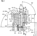
- Figure 1 shows a feedback stage RC of a radial turbo machine RTM, which is designed as a radial turbo compressor CO.
- a radial turbo compressor CO can also be implemented according to the invention, identical in construction, as radial turbo expanders, with a process fluid PF flowing through these components in a radial turbo compressor CO in a first flow direction FD1 and in a radial turbo expander in an opposite, second flow direction FD2.
- the descriptions in this document always refer to the first flow direction FD1, unless otherwise stated.
- Figure 1 shows parts of two successive stages through which flow occurs, a first stage ST1 and a second stage ST2 of a radial turbo machine RTM or radial turbo compressor CO shown in detail, with a return stage RTC between the two stages ST1, ST2 being shown completely schematically.
- the two stages ST1, ST2 are shown here with impellers arranged to be rotatable about the axis of rotation X, a first impeller IP1 and a second impeller IP2.
- a process fluid PF first flows through the first impeller IP1, flowing in axially and flowing out radially along a first flow direction FD1.
- An oppositely oriented second flow direction FD2 is also given as an example, as would be the case with a radial expander.
- the process fluid PF flowing radially outward, reaches a radially outwardly directed first section SG1 and is decelerated there, passes downstream into an approximately 180 ° deflection of a second section SG2 and then into a radially inward one Return of a third section SG3 of the return stage RTC.
- the process fluid PF reaches the second impeller IP2 in a fourth section SG4, flowing radially inward, deflected in an axially flowing direction, in order to be accelerated radially outward there again.
- the return stage RTC comprises a blade bottom RR, guide blades VNS and an intermediate bottom DGP.
- the intermediate floor DGP is supported by at least one support SUP in a support device - here in a housing CAS - and positioned there.
- the support SUP and the supporting section of the housing CAS are designed as a tongue and groove connection in a form-fitting manner.
- the return stage has RTC or the blade bottom RR and the intermediate bottom DGP has a joint that runs in a common plane essentially along the X axis.
- This parting line is conveniently located in the same parting line as a parting line, not shown, of the CAS housing.
- the rotor is designed to be divisible between two impellers or the impellers are designed to be axially displaceable in relation to one another for the purpose of assembly, so that the return stages RTC can be designed undivided and gradually assembled together with the impellers IP1, IP2 of the rotor before merging with a surrounding housing takes place.
- the housing CAS can in any case be designed to be divided horizontally or vertically.
- the conventional design of the return stage RTC which is in the Figure 1 is shown, provides that the blade base RR, the guide vanes VNS and the intermediate base DGP are attached to one another. In the present case, this is done using SCR screws, which are shown in simplified form by means of dash-dotted lines. So that the screws SCR on the one hand adequately fasten the blade bottom RR to the intermediate bottom DGP and must therefore have a minimum thickness, on the other hand a sufficiently large through-hole must be provided in the guide vanes VNS so that the profile of the guide vanes VNS must be sufficiently strong.
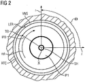
- FIG Figure 2 shows schematically a cross section through a radial turbine machine RTM according to the invention, as shown in FIG Figure 1 is shown with II-II.
- the one mounted on the SH shaft The first impeller IP1 is mounted so that it can rotate about the axis X along the direction of rotation ROT. The directions radially, horizontally and vertically are drawn as an example.
- the circumferential position angle 8 runs positively against the direction of rotation ROT.
- the first impeller IP1 has moving blades IPB of a moving blade stage, shown as an example.
- the trailing edge TEI is entered for a rotor blade IPB.
- the return stage RTC extends downstream of the first impeller IP1.
- the return stage RTC has a guide vane stage VST with guide vanes VNS, one of which is shown as an example.
- the guide vane VNS shown schematically is only shown with its leading edge LER.
- Overall shows the Figure 2 the relationship between the direction of rotation ROT of the shaft SH or the running wheels IP1, IP2 and the circumferential position angle ⁇ .
- Figure 3 shows three-dimensional parts of the return stage RTC, namely the guide vane stage VST with the guide vanes VNS and their three-dimensional design.
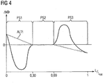
- the Figure 4 shows the course of the difference between the circumferential position angle of the outer track to the inner track plotted over the profile center line coordinate L, which is specified normalized to an entire length l.
- a first alternative ALT1 provides that the difference is initially positive and then drops to 0 at approx. 0.3L and there is constant until it drops into negative at approx. 0.65L ⁇ .
- a second alternative ALT2 provides that the circumferential position angle difference ⁇ is initially positive in the area of the leading edge LER, then drops into the negative, has a local minimum there and rises again up to a difference of 0 at around 0.3L. There, ⁇ remains constant up to about 0.65L and then rises to the positive, up to a local maximum, and then falls back to the negative.
Description
Die Erfindung betrifft eine Rückführstufe zur Durchströmung mittels eines Prozessfluids entlang einer Durchströmungsrichtung einer Radialturbomaschine, insbesondere Radialturboverdichterrückführstufe, wobei die Rückführstufe sich ringförmig um eine Achse erstreckt, wobei die Rückführstufe nach radial innen von einer inneren Grenzkontur und nach radial außen von einer äußeren Grenzkontur definiert ist, wobei entlang einer ersten Durchströmungsrichtung die Rückführstufe sich in einem ersten Abschnitt nach radial außen erstreckt, wobei die Rückführstufe sich in einem zweiten Abschnitt entlang der ersten Durchströmungsrichtung eine bogenförmige Umlenkung beschreibend von radial außen nach radial innen erstreckt, wobei die Rückführstufe sich entlang der ersten Durchströmungsrichtung in einem dritten Abschnitt von radial außen nach radial innen erstreckt, wobei die Rückführstufe sich entlang der ersten Durchströmungsrichtung in einem vierten Abschnitt eine bogenförmige Umlenkung beschreibend von radial innen nach axial erstreckt, wobei mindestens eine Leitschaufelstufe umfassend Leitschaufeln sich zumindest entlang eines Teils des dritten Abschnitts erstreckt und die Rückführstufe in Umfangsrichtung in Strömungskanäle segmentiert, wobei jeweils eine Profilmittellinie eines Profilquerschnitts der Leitschaufeln der Leitschaufelstufe seitens der inneren Grenzkontur eine innere Spur und seitens der äußeren Grenzkontur eine äußere Spur definiert. Daneben betrifft die Erfindung eine Radialturbomaschine, insbesondere einen Radialturboverdichter mit mindestens einer derartigen Rückführstufe.The invention relates to a return stage for throughflow by means of a process fluid along a flow direction of a radial turbomachine, in particular a radial turbo compressor return stage, the return stage extending in a ring around an axis, the return stage being defined radially inward by an inner boundary contour and radially outward by an outer boundary contour, wherein, along a first flow direction, the return stage extends radially outward in a first section, wherein the return stage extends in a second section along the first flow direction, describing an arcuate deflection, from radially outside to radially inward, the return stage extending along the first flow direction in a third section extending from radially outward to radially inward, the return stage extending along the first flow direction in a fourth section describing an arcuate deflection extending from radially inside to axially, with at least one guide vane stage comprising guide vanes extending at least along part of the third section and segmenting the return stage in the circumferential direction into flow channels, with a profile center line of a profile cross section of the guide vanes of the guide vane stage on the part of the inner boundary contour and an inner track on the side the outer boundary contour defines an outer track. In addition, the invention relates to a radial turbo machine, in particular a radial turbo compressor with at least one such return stage.
Radialturbomaschinen sind entweder als Radialturboverdichter oder Radialturboexpander bekannt. Die nachfolgenden Ausführungen beziehen sich - wenn nicht anders angegeben - auf die Ausführung als Verdichter. Die Erfindung ist für Expander grundsätzlich genauso anwendbar, wie für Verdichter, wobei ein Radialturboexpander gegenüber einem Radialturboverdichter im Wesentlichen eine umgekehrte Strömungsrichtung des Prozessfluids vorsieht.Radial turbo machines are known as either radial turbo compressors or radial turbo expanders. Unless otherwise stated, the following statements refer to the version as a compressor. The invention is basically just as applicable for expanders as it is for compressors, a radial turbo expander compared to a radial turbo compressor essentially provides a reverse flow direction of the process fluid.
Unter Entspannung und Umlenkung eines Prozessfluid findet bei einem Radialturboexpander eine Umwandlung der thermodynamisch im Prozessfluid gespeicherten Energie in technische Arbeit mittels Antriebs des Laufrads statt.
Bei Radialturboverdichter ist dieser Vorgang umgekehrt, diese wandeln bzw. speichern technische Arbeit in Strömungsarbeit, die thermodynamisch im Prozessfluid gespeichert wird. Hierzu saugen Laufräder des Verdichters in der Regel ein Prozessfluid axial zu einer Rotationsachse oder schräg zu der Rotationsachse mit einer axialen Geschwindigkeitskomponente an und beschleunigen und verdichten dieses Prozessfluid mittels des jeweiligen Laufrads - das auch als Impeller bezeichnet wird - , das die Strömungsrichtung des Prozessfluids in die radiale Richtung umlenkt. An das Laufrad schließt sich bei einem mehrstufigen Radialturboverdichter stromabwärts eine Rückführstufe an, wenn stromabwärts mindestens ein weiteres Laufrad vorgesehen ist.With a radial turbo expander, the energy stored thermodynamically in the process fluid is converted into technical work by means of a drive of the impeller while a process fluid is relaxed and deflected.
In the case of radial turbo compressors, this process is reversed; these convert or store technical work into flow work that is stored thermodynamically in the process fluid. For this purpose, the impellers of the compressor usually suck in a process fluid axially to an axis of rotation or at an angle to the axis of rotation with an axial speed component and accelerate and compress this process fluid by means of the respective impeller - which is also referred to as an impeller - which controls the flow direction of the process fluid deflects radial direction. In the case of a multistage radial turbo compressor, the impeller is followed downstream by a return stage if at least one further impeller is provided downstream.
Eine mehrstufige Radialturbomaschine bedeutet in der Begriffswelt dieser Erfindung, dass mehrere Laufräder um die gleiche Rotationsachse drehbar angeordnet sind. Hierbei ist ein Laufrad gleichzusetzen mit einer Stufe der Radialturbomaschine. Aus der Mehrstufigkeit ergibt sich das Erfordernis, dass im Falle des Verdichters das radial aus dem Laufräder ausströmende Prozessfluid wieder zurück in Richtung der Rotationsachse geführt werden muss und mit einer axialen Geschwindigkeitskomponente in das nachfolgende Laufrad der stromabwärtigen Stufe einströmen kann. Die Strömungsführung, die diese Rückführung des Prozessfluids ermöglicht nennt sich daher "Rückführstufe". Im Falle des Expanders kann das Bauteil identisch ausgebildet sein und wird lediglich in umgekehrter Richtung durchströmt.In the terminology of this invention, a multistage radial turbo machine means that several running wheels are arranged to be rotatable about the same axis of rotation. Here, an impeller is to be equated with a stage of the radial turbomachine. The multistage requires that, in the case of the compressor, the process fluid flowing radially out of the impellers must be guided back in the direction of the axis of rotation and can flow into the subsequent impeller of the downstream stage with an axial speed component. The flow guidance that enables this return of the process fluid is therefore called the "return stage". In the case of the expander, the component can be of identical design and the flow is only flowed through in the opposite direction.
Neben der Rückführung des Prozessfluides in Richtung der Rotationsachse und der Umlenkung der Strömungsrichtung des Prozessfluids in axiale Richtung sind in den Rückführstufen regelmäßig auch Leitschaufeln vorgesehen, die einen in der Strömung aus dem stromaufwärtigen Laufrad aufgeprägten Drall zumindest teilweise oder vollständig neutralisieren oder sogar einen Drall in Gegenrichtung aufprägen für den Eintritt in die nächste stromabwärtige Stufe.In addition to the return of the process fluid in the direction of the axis of rotation and the deflection of the flow direction of the process fluid In the axial direction, guide vanes are also regularly provided in the return stages, which at least partially or completely neutralize a swirl imposed in the flow from the upstream impeller or even imprint a swirl in the opposite direction for entry into the next downstream stage.
Die übliche Ausfertigung einer Rückführstufe sieht vor, dass dieses Gesamtbauteil mittels eines sogenannten Zwischenbodens mittels geeigneter Auflager in der Regel in einem Gehäuse oder einer sonstigen Auflagevorrichtung abgestützt und ausgerichtet ist. Weiterhin umfasst die Rückführstufe einen sogenannten Schaufelboden, der an dem Zwischenboden mit den bereits erläuterten Leitschaufeln unter Ausbildung eines Rückführkanals befestigt ist. Durch den Rückführkanal strömt das Prozessfluid zum nächsten Laufradeintritt. In diesem Gebilde kommen den Leitschaufeln zwei Funktionen zu. Einerseits haben die Leitschaufeln die aerodynamische Funktion, dem Prozessfluid einen Gegendrall soweit aufzuprägen, dass zumindest der Drall aus der stromaufwärtigen Stufe weitestgehend kompensiert ist und andererseits haben die Leitschaufeln die mechanische Aufgabe, den Schaufelboden an dem Zwischenboden derart zu befestigen, dass trotz der dynamischen Belastung ein sicherer Halt gewährleistet ist.The usual design of a return stage provides that this overall component is supported and aligned by means of a so-called intermediate floor by means of suitable supports, usually in a housing or some other support device. Furthermore, the return stage comprises a so-called vane bottom, which is attached to the intermediate bottom with the guide vanes already explained, forming a return channel. The process fluid flows through the return channel to the next impeller inlet. In this structure, the guide vanes have two functions. On the one hand, the guide vanes have the aerodynamic function of imposing a counter-swirl on the process fluid to the extent that at least the swirl from the upstream stage is largely compensated for, and on the other hand, the guide vanes have the mechanical task of fastening the vane bottom to the intermediate bottom in such a way that, despite the dynamic load, a a secure hold is guaranteed.
In den Schriften
Die herkömmlichen Rückführstufen des Standes der Technik weisen unterschiedliche Nachteile auf, die die Erfindung zu vermeiden versucht. Die geometrisch eher einfach gestalteten Rückführstufen sind zum größten Teil aerodynamisch schlechter an die strömungstechnische Aufgabe angepasst, so dass die komplexe dreidimensionale Strömungssituation zumindest teilweise unberücksichtigt bleibt, insbesondere über die Schaufelhöhe bleiben Unterschiede unbeachtet und dementsprechend treten unverhältnismäßig große Strömungsverluste auf, die den Wirkungsgrad mindern. Andere Lösungen, insbesondere die Rückführstufe nach
Die Erfindung hat es sich daher zur Aufgabe gemacht, die Eigenschaften vereinfachte Fertigung, optimierte Aerodynamik und einfache Montage miteinander zu vereinen.The invention has therefore set itself the task of combining the properties of simplified production, optimized aerodynamics and simple assembly.
Zur Lösung der Aufgabe wird erfindungsgemäß eine Rückführstufe bzw. eine Radialturbomaschine gemäß der Ansprüche 1 bzw. 8 vorgeschlagen. Die jeweils rückbezogenen Unteransprüche beinhalten vorteilhafte Weiterbildungen der Erfindung.In order to achieve the object, a recirculation stage or a radial turbo machine according to claims 1 and 8 is proposed according to the invention. The respective back-referenced subclaims contain advantageous developments of the invention.
Grundsätzlich dient die Rückführstufe einer Radialturbomaschine dazu, das Prozessfluid von einem stromaufwärts gelegenen Laufrad aus der nach radial außen gerichteten Strömungsrichtung wieder nach radial innen umzulenken und axial dem nachfolgenden stromabwärts gelegenen Laufrad zuzuführen. Die Begriffe axial, radial, tangential, Umfangsrichtung und ähnliche werden hierbei bzw. in diesem Dokument jeweils auf die zentrale Achse bezogen, um die sich die Rückführstufe ringförmig erstreckt. Diese Achse ist bei einer Radialturbomaschine auch die Rotationsachse eines Rotors bzw. der Welle mit den Laufrädern.Basically, the recirculation stage of a radial turbo machine is used to divert the process fluid from an upstream impeller from the radially outward flow direction to the radially inward direction and to feed it axially to the following downstream impeller. The terms axial, radial, tangential, circumferential direction and the like are here or in this document each related to the central axis around which the return stage extends in an annular manner. In the case of a radial turbo machine, this axis is also the axis of rotation of a rotor or the shaft with the running wheels.
Die sich in der Rückführstufe befindende Leitschaufelstufe umfasst Leitschaufeln, die die Ringform der Rückführstufe in Umfangsrichtung in einzelne Kanäle segmentieren. Grundsätzlich können diese Leitschaufeln auch Unterbrechungen (split) aufweisen, sind aber nach der Erfindung bevorzugt entlang der ersten Strömungsrichtung ununterbrochen ausgebildet. Die Leitschaufeln weisen Profile auf, die sich - entsprechend abgewickelt - auch zweidimensional darstellen lassen. Eine zweidimensionale Darstellung ist beispielsweise möglich, wenn der ringförmige Kanal der Rückführstufe entlang einer sich in Umfangsrichtung erstreckenden mittleren Fläche geschnitten wird. Diese Schnittfläche einer einzelnen Leitschaufel lässt sich in eine Ebene abwickeln, zu einer zweidimensionalen Darstellung. Eine Profilmittellinie der aufeinandergestapelten Profile der Leitschaufeln ist erzeugbar mittels Mittelpunkten eingeschriebener Kreise in dem Profil.The guide vane stage located in the return stage comprises guide vanes which segment the annular shape of the return stage into individual channels in the circumferential direction. In principle, these guide vanes can also have interruptions (split), but according to the invention are preferably designed to be uninterrupted along the first flow direction. The guide vanes have profiles which - if unwound accordingly - can also be represented in two dimensions. A two-dimensional representation is possible, for example, if the annular channel of the return stage is cut along a central surface extending in the circumferential direction. This cut surface of a single guide vane can be developed into a plane, for a two-dimensional representation. A profile center line of the stacked profiles of the guide vanes can be generated by means of centers of inscribed circles in the profile.
Auf diese Weise lässt sich eine Profilmittellinienlaufkoordinate entlang der ersten Durchströmungsrichtung entlang einer mittleren Höhe der jeweiligen Leitschaufel definieren. Die Länge der Leitschaufel entlang dieser Koordinate ist zweckmäßig normiert auf eine Gesamtlänge 1.In this way, a profile center line running coordinate can be defined along the first flow direction along a mean height of the respective guide vane. The length of the guide vane along this coordinate is expediently normalized to a total length 1.
Die Höhenrichtung der Leitschaufel wird vorliegend als die Richtung definiert, die senkrecht zu der Durchströmungsrichtung - insbesondere zur ersten Durchströmungsrichtung - und senkrecht zu der Umfangsrichtung orientiert ist.The height direction of the guide vane is defined in the present case as the direction which is oriented perpendicular to the flow direction - in particular to the first flow direction - and perpendicular to the circumferential direction.
Die Profilmittellinie der Leitschaufel unmittelbar angrenzend an der äußeren Grenzkontur des ringförmigen Kanals der Rückführstufe wird hier als äußere Spur der Leitschaufel bezeichnet und die Profilmittellinie des unmittelbar an der inneren Grenzkontur befindlichen Profilquerschnitts der Leitschaufel wird als die innere Spur der Leitschaufel bezeichnet. In diesem Zusammenhang kann die äußere Grenzkontur der Rückführstufe auch als deckscheibenseitige Grenzkontur bezeichnet werden, weil ein mit einer Deckscheibe versehenes Laufrad diese Deckscheibe auf der Seite der äußeren Grenzkontur aufweist.The profile center line of the guide vane immediately adjacent to the outer boundary contour of the annular channel of the return stage is referred to here as the outer track of the guide vane and the profile center line of the profile cross-section of the guide vane located directly on the inner boundary contour is referred to as the inner track of the guide vane. In this context, the outer boundary contour of the return stage can also be referred to as the boundary contour on the cover disk side, because an impeller provided with a cover disk has this cover disk on the side of the outer boundary contour.
Die nabenseitige Strömungskontur des Laufrades befindet sich dazu gegenüberliegend auf der inneren Grenzkontur der Rückführstufe, so dass die innere Grenzkontur der Rückführstufe auch als nabenseitige Grenzkontur bezeichnet werden kann. Entlang der komplexen Geometrie der Rückführstufe kann die innere Grenzkontur nicht immer als radial weiter innen liegend angesehen werden als die äußere Grenzkontur für gleiche Positionen entlang einer mittleren Strömungslinie durch die Rückführstufe, so dass derartige alternative Bezeichnungen zum besseren Verständnis zweckmäßig sind.The hub-side flow contour of the impeller is located opposite on the inner boundary contour of the return stage, so that the inner boundary contour of the return stage can also be referred to as the hub-side boundary contour. Due to the complex geometry of the return stage, the inner limit contour cannot always be viewed as being located radially further inward than the outer limit contour for the same positions along a central flow line through the return stage, so that such alternative designations are useful for better understanding.
Der Umfangspositionswinkel bestimmt die jeweilige Position in Umfangsrichtung der in Bezug genommenen Bauteile - hier im Wesentlichen Referenzpunkte oder Linien der Leitschaufeln, z.B. Punkte auf Profilmittelinien von bestimmten Profilquerschnitten. Die positive Verlaufsrichtung des Umfangspositionswinkels ist hierbei entgegen der Rotationsrichtung der Welle bzw. des Rotors gewählt. Der Scheitelpunkt dieses Winkels fällt mit der zentralen Achse zusammen. Für den Fachmann ist die Rückführstufe stets mit einer strömungstechnischen Aufgabenstellung verbunden, so dass eine Loslösung der Begriffswelt der Rückführstufe von der Rotationsrichtung der Turbomaschine grundsätzlich nicht zweckmäßig ist.The circumferential position angle determines the respective position in the circumferential direction of the components referred to - here essentially reference points or lines of the guide vanes, e.g. Points on profile center lines of certain profile cross-sections. The positive direction of the circumferential position angle is selected here against the direction of rotation of the shaft or the rotor. The vertex of this angle coincides with the central axis. For the person skilled in the art, the recirculation stage is always associated with a fluidic task, so that it is fundamentally not expedient to detach the terminology of the recirculation stage from the direction of rotation of the turbo machine.
Die drei Profilabschnitte der Leitschaufeln der Leitschaufelstufe unterscheiden sich aufgrund der Schwerpunkte ihrer Funktionen erfindungsgemäß voneinander. Der erste und der dritte Profilabschnitt stehen in starkem Zusammenhang mit einer bogenförmigen Umlenkung des Prozessfluids, wobei der zweite Profilabschnitt weniger die bogenförmige Umlenkung als strömungstechnische Aufgabe aufweist. Alle drei Profilabschnitte stehen im Zusammenhang entweder mit einer Verzögerung oder Beschleunigung des Prozessfluids, so dass auch dahingehend anspruchsvolle überlagerte aerodynamische Vorgänge stattfinden. Der zweite Profilabschnitt ist darüber hinaus noch besonders bevorzugt, der Hindurchführung mindestens eines Befestigungselementes für den Zwischenboden an dem Schaufelboden zu dienen. Diesen Gegebenheiten trägt die Erfindung im besonderen Maße Rechnung. Vorteilhaft homogenisiert die Erfindung die Strömung über die Höhenerstreckung der Leitschaufeln, indem jeweils für Werte von L in den Profilabschnitten gilt:
- in dem ersten Profilabschnitt (PS1):

- in dem zweiten Profilabschnitt (PS2) : OTR (L) =θITR (L) und

- in dem dritten Profilabschnitt (PS3):

- in the first profile section (PS1):
- in the second profile section (PS2): OTR (L) = θ ITR (L) and
- in the third profile section (PS3):
Besonders zweckmäßig ist eine weiterbildende Ausbildung, bei der in dem ersten Profilabschnitt gilt: ![]()
![]()
![]()
![]()
Eine vorteilhafte Weiterbildung der Erfindung sieht vor, dass gilt: ![]()
![]()
![]()
![]()
Der mittlere, zweite Profilabschnitt erstreckt sich vorteilhaft von höchstens L=0,4 bis mindestens L=0,6.The middle, second profile section advantageously extends from at most L = 0.4 to at least L = 0.6.
Zur Befestigung des Zwischenbodens an dem Schaufelboden ist es sinnvoll, wenn zumindest einige der Leitschaufeln in dem zweiten Profilabschnitt eine sich von einem Punkt der Innenspur zu einem Punkt der Außenspur erstreckende Ausnehmung aufweisen zur Durchführung eines Befestigungselements zwischen der inneren Grenzkontur und der äußeren Grenzkontur. Bevorzugt ist diese Ausnehmung zu den lateralen Schaufelprofiloberflächen hin geschlossen. Besonders bevorzugt weist die Ausnehmung eine zentrale gerade Erstreckungsachse auf und kann insbesondere als Bohrung ausgeführt sein.To fasten the intermediate base to the vane base, it makes sense if at least some of the guide vanes in the second profile section have a recess extending from a point on the inner track to a point on the outer track for the implementation of a fastening element between the inner boundary contour and the outer boundary contour. This recess is preferably closed towards the lateral blade profile surfaces. The recess particularly preferably has a straight central extension axis and can in particular be designed as a bore.
Der Wirkungsgrad der Rückführstufe kann weiter optimiert werden, wenn die Leitschaufeln jeweils mit einer Eintrittskante jeweils in dem zweiten Abschnitt angeordnet sind, bevorzugt in einem Bereich der bogenförmigen Umlenkung des zweiten Abschnitts zwischen 0°-90° eines ersten Umlenkungswinkels zur zentralen Achse.The efficiency of the return stage can be further optimized if the guide vanes each have a leading edge are each arranged in the second section, preferably in a region of the arcuate deflection of the second section between 0 ° -90 ° of a first deflection angle to the central axis.
Der Umlenkungswinkel ist bei den bogenförmigen Umlenkungen in der Rückführstufe jeweils die Winkeldifferenz einer Projektion der jeweiligen Durchströmungsrichtung, insbesondere der ersten Durchströmungsrichtung, der Rückführstufe in einer axial-radialen Ebene eingangs zu ausgangs des betrachteten umlenkenden Abschnitts.In the case of the curved deflections in the return stage, the deflection angle is the angle difference of a projection of the respective flow direction, in particular the first flow direction, of the return stage in an axial-radial plane at the beginning to the exit of the deflecting section under consideration.
Eine weitere Verbesserung der Aerodynamik ergibt sich dadurch, dass die Leitschaufeln jeweils mit einer Austrittskante jeweils in dem vierten Abschnitt angeordnet sind, bevorzugt in einem Bereich der bogenförmigen Umlenkung des vierten Abschnitts zwischen 0°-60° zweiten Umlenkungswinkel zur Achse.A further improvement in aerodynamics results from the fact that the guide vanes are each arranged with a trailing edge in the fourth section, preferably in an area of the arcuate deflection of the fourth section between 0 ° -60 ° second deflection angle to the axis.
Eine Radialturbomaschine nach der Erfindung umfasst eine Rückführstufe der bereits beschriebenen Art, wobei die Achse, um die sich die Rückführstufe ringförmig erstreckt mit der Rotationsachse eines Rotors bzw. einer Welle, die Laufräder trägt, identisch ist. Die Rückführstufe führt hierbei die Strömung entlang der ersten Durchströmungsrichtung von einem Laufrad zu einem stromabwärts gelegenen Laufrad.A radial turbomachine according to the invention comprises a return stage of the type already described, the axis around which the return stage extends in the form of a ring being identical to the axis of rotation of a rotor or a shaft which carries running wheels. The return stage leads the flow along the first flow direction from an impeller to an impeller located downstream.
Besonders zweckmäßig ermöglicht die Erfindung, dass das Verhältnis von einem Zwischendurchmesser zu einem Austrittsdurchmesser kleiner als 1,5, insbesondere kleiner als 1,4 ist, wobei der Austrittsdurchmesser der Austrittsdurchmesser des stromaufwärts der Rückführstufe gelegenen Laufrades ist und der Zwischendurchmesser der Durchmesser des Übergangsquerschnitts der Rückführstufe von dem ersten Abschnitt zu dem zweiten Abschnitt ist.The invention particularly expediently enables the ratio of an intermediate diameter to an outlet diameter to be smaller than 1.5, in particular smaller than 1.4, the outlet diameter being the outlet diameter of the impeller located upstream of the return stage and the intermediate diameter being the diameter of the transition cross section of the return stage from the first section to the second section.
Im Folgenden ist die Erfindung anhand eines speziellen Ausführungsbeispiels unter Bezugnahme auf Zeichnungen näher erläutert. Es zeigen schematisch:
- Figur 1
- ein axialer Längsschnitt durch den Ausschnitt eines Gehäuses einer Radialturbomaschine mit einer Rückführstufe und Laufrädern,
- Figur 2
- zeigt eine Darstellung eines Querschnitts gemäß dem in
Figur 1 ausgewiesenen Schnitt II-II, - Figur 3
- zeigt eine dreidimensionale Widergabe der Leitschaufelstufe einer erfindungsgemäßen Rückführstufe zusammen mit einem Zwischenboden und
- Figur 4
- zeigt den Umfangspositionswinkeldifferenzverlauf zwischen der äußeren Spur und der inneren Spur der Profilmittellinie einzelner Leitschaufeln der Leitschaufelstufe der Rückführstufe aufgetragen über die auf 1 (dimensionslos) normierte Profillängenlaufkoordinate entlang der ersten Strömungsrichtung.
- Figure 1
- an axial longitudinal section through the section of a housing of a radial turbomachine with a return stage and impellers,
- Figure 2
- FIG. 11 shows a representation of a cross section according to FIG
Figure 1 designated section II-II, - Figure 3
- shows a three-dimensional representation of the guide vane stage of a return stage according to the invention together with an intermediate floor and
- Figure 4
- shows the circumferential position angle difference profile between the outer track and the inner track of the profile center line of individual guide vanes of the guide vane stage of the return stage plotted over the profile length coordinate normalized to 1 (dimensionless) along the first flow direction.
Die hier beispielhaft für einen Radialturboverdichter CO erläuterten Bauteile sind bauidentisch erfindungsgemäß auch umsetzbar als Radialturboexpander, wobei ein Prozessfluid PF diese Bauteile in einem Radialturboverdichter CO in einer ersten Durchströmungsrichtung FD1 und in einem Radialturboexpander in einer entgegengesetzten zweiten Durchströmungsrichtung FD2 durchströmt. Die Schilderungen beziehen sich in diesem Dokument stets auf die erste Durchströmungsrichtung FD1, sofern nicht anders angegeben.The components explained here by way of example for a radial turbo compressor CO can also be implemented according to the invention, identical in construction, as radial turbo expanders, with a process fluid PF flowing through these components in a radial turbo compressor CO in a first flow direction FD1 and in a radial turbo expander in an opposite, second flow direction FD2. The descriptions in this document always refer to the first flow direction FD1, unless otherwise stated.
Ein Prozessfluid PF durchströmt in der Darstellung der Figur 1 zunächst das erste Laufrad IP1 axial einströmend und radial ausströmend entlang einer ersten Durchströmungsrichtung FD1. Nur beispielhaft ist auch eine entgegengesetzt ausgerichtete zweite Durchströmungsrichtung FD2 angegeben, wie diese vorläge bei einem Radialexpander. Stromabwärts anschließend an das erste Laufrad IP1 erreicht das Prozessfluid PF radial nach außen strömend einen radial nach außen gerichteten ersten Abschnitt SG1 und wird dort verzögert, gelangt stromabwärts in eine ca. 180°-Umlenkung eines zweiten Abschnitts SG2 und anschließend in eine radial nach innen gerichtete Rückführung eines dritten Abschnitts SG3 der Rückführstufe RTC. Stromabwärts des dritten Abschnitts SG3 gelangt das Prozessfluid PF in einem vierten Abschnitt SG4 von radial nach innen strömend nach axial strömend umgelenkt in das zweite Laufrad IP2, um dort wieder radial nach außen beschleunigt zu werden.In the illustration in FIG. 1, a process fluid PF first flows through the first impeller IP1, flowing in axially and flowing out radially along a first flow direction FD1. An oppositely oriented second flow direction FD2 is also given as an example, as would be the case with a radial expander. Downstream of the first impeller IP1, the process fluid PF, flowing radially outward, reaches a radially outwardly directed first section SG1 and is decelerated there, passes downstream into an approximately 180 ° deflection of a second section SG2 and then into a radially inward one Return of a third section SG3 of the return stage RTC. Downstream of the third section SG3, the process fluid PF reaches the second impeller IP2 in a fourth section SG4, flowing radially inward, deflected in an axially flowing direction, in order to be accelerated radially outward there again.
Die Rückführstufe RTC umfasst einen Schaufelboden RR, Leitschaufeln VNS und einen Zwischenboden DGP. Der Zwischenboden DGP ist mittels mindestens eines Auflagers SUP in einer Auflagervorrichtung - hier in einem Gehäuse CAS - abgestützt und dort positioniert. Das Auflager SUP und der abstützende Abschnitt des Gehäuses CAS sind hierbei als Nut-Feder-Verbindung formschlüssig ausgebildet.The return stage RTC comprises a blade bottom RR, guide blades VNS and an intermediate bottom DGP. The intermediate floor DGP is supported by at least one support SUP in a support device - here in a housing CAS - and positioned there. The support SUP and the supporting section of the housing CAS are designed as a tongue and groove connection in a form-fitting manner.
In nicht näher dargestellter Weise weist die Rückführstufe RTC bzw. weisen der Schaufelboden RR und der Zwischenboden DGP eine Teilfuge auf, die in einer gemeinsamen Ebene im Wesentlichen entlang der Achse X verläuft. Zweckmäßig für die Montage ist diese Teilfuge in der identischen Teilfugenebene gelegen, wie eine nicht dargestellte Teilfuge des Gehäuses CAS.In a manner not shown in more detail, the return stage has RTC or the blade bottom RR and the intermediate bottom DGP has a joint that runs in a common plane essentially along the X axis. This parting line is conveniently located in the same parting line as a parting line, not shown, of the CAS housing.
Grundsätzlich ist es auch denkbar, dass der Rotor zwischen zwei Laufrädern teilbar ausgebildet ist oder die Laufräder axial zueinander zum Zwecke der Montage verschieblich ausgebildet sind, so dass die Rückführstufen RTC ungeteilt ausgebildet sein können und schrittweise mit den Laufrädern IP1, IP2 des Rotors zusammen montiert werden bevor ein Zusammenführung mit einem umgebenden Gehäuse stattfindet. Das Gehäuse CAS kann jedenfalls horizontal oder vertikal geteilt ausgebildet sein.In principle, it is also conceivable that the rotor is designed to be divisible between two impellers or the impellers are designed to be axially displaceable in relation to one another for the purpose of assembly, so that the return stages RTC can be designed undivided and gradually assembled together with the impellers IP1, IP2 of the rotor before merging with a surrounding housing takes place. The housing CAS can in any case be designed to be divided horizontally or vertically.
Die herkömmliche Ausbildung der Rückführstufe RTC, die in der
Die Leitschaufeln sind entlang der ersten Durchströmungsrichtung FD1 in drei aufeinanderfolgende Profilabschnitte PS aufgeteilt:
- einen ersten Profilabschnitt PS1,
- einen zweiten Profilabschnitt PS2,
- einen dritten Profilabschnitt PS3.
- a first profile section PS1,
- a second profile section PS2,
- a third profile section PS3.
Die
Claims (9)
- Return stage (RTC) for throughflow by means of a process fluid along a throughflow direction of a radial turbomachine (RTM), in particular radial turbocompressor return stage (RCC), wherein the return stage (RTC) extends about an axis (X) in a ring-shaped manner,
wherein the return stage (RTC) is defined radially inwardly by an inner delimiting contour (IDC) and radially outwardly by an outer delimiting contour (ODC),
wherein the return stage (RTC) extends radially outwardly in a first section (SG1) along a first throughflow direction (FD1), wherein the return stage (RTC) extends, in a manner describing an arcuate deflection, radially inwardly from radially outside along the first throughflow direction (FD1) in a second section (SG2),
wherein the return stage (RTC) extends radially inwardly from radially outside along the first throughflow direction (FD1) in a third section (SG3),
wherein the return stage (RTC) extends, in a manner describing an arcuate deflection, axially from radially inside along the first throughflow direction (FD1) in a fourth section (SG4), wherein at least one guide vane stage (VST) comprising guide vanes (VNS) extends at least along a part of the third section (SG3) and, in the circumferential direction, segments the return stage into flow channels,
wherein in each case a profile midline (PML) of a profile cross section (PRC) of the guide vanes (VNS) of the guide vane stage (VST) defines an inner track (ITR) on the side of the inner delimiting contour (IDC) and an outer track (OTR) on the side of the outer delimiting contour (ODC),
wherein the progressions of the inner track (ITR) and outer track (OTR) are able to be defined as:
 θ: circumferential position angle in a direction of rotation of the radial turbomachine (RTM), with the vertex on an axis (X),L: profile midline path coordinate along the first throughflow direction (FD1) along a mid-height of the respective guide vane (VNS), normalized to a total length of 1,Fθ(L): functional relationship between circumferential position angle θ and position L on the profile midline,R: radius of the position of the inner track (ITR) or outer track (OTR),wherein the guide vanes (VNS) have three successive profile sections (PS) along the first throughflow direction (FD1):a first profile section (PS1),a second profile section (PS2),a third profile section (PS3),characterized
in that, in each case for values of L in the profile sections, it holds that:in the first profile section (PS1): in the second profile section (PS2):
 in the third profile section (PS3):
- Return stage (RTC) according to Claim 1, wherein, in the first profile section (PS1), it holds that:


- Return stage (RTC) according to Claim 1 or 2, wherein it holds that:


- Return stage (RTC) according to Claim 1, 2 or 3,
wherein the second profile section (PS2) extends from at most L=0.4 to at least L=0.6. - Return stage (RTC) according to Claim 1, 2, 3 or 4, wherein at least some of the guide vanes (VNS) have a cutout in the second profile section (PS2), extending from a point of the inner track to a point of the outer track, for the leadthrough of a fastening element between the inner delimiting contour (IDC) and the outer delimiting contour (ODC).
- Return stage (RTC) according to Claim 1, 2, 3, 4 or 5, wherein the guide vanes (VNS) are in each case arranged with an inlet edge (LER) in each case in the second section (SG2), preferably in a region of the arcuate deflection of the second section (SG2) between 0° and 90° of a first deflection angle (BA1) .
- Return stage (RTC) according to Claim 1, 2, 3, 4, 5 or 6, wherein the guide vanes (VNS) are in each case arranged with an outlet edge (VTE) in each case in the fourth section (SG4), preferably in a region of the arcuate deflection of the fourth section (SG4) between 0° and 60° of a second deflection angle (BA2) .
- Radial turbomachine (RTM), in particular radial turbocompressor, having at least one return stage (RTC) according to Claim 1, 2, 3, 4, 5, 6 or 7, wherein the radial turbomachine (RTM) has a rotor (ROT) which is mounted in a manner rotatable about the axis (X) and which comprises at least two impellers (IP1, IP2), wherein the return stage (RTC) guides the flow from one impeller (IP1, IP2) to a downstream impeller (IP1, IP2) along the first throughflow direction (FD1).
- Radial turbomachine (RTM) according to Claim 8,
wherein the impellers (IP1, IP2) have an outlet diameter (D2) upstream of the return stage (RTC), wherein the transition cross section of the return stage from the first section (SG1) to the second section (SG2) is arranged at an intermediate diameter (DRR), wherein it holds that:
DRR/D2 < 1.5, in particular DRR/D2 < 1.4,
with:D2: outlet diameter of impellers (IP1, IP2)DRR: intermediate diameter of transition cross section of the return stage from the first section (SG1) to the second section (SG2).
Applications Claiming Priority (2)
| Application Number | Priority Date | Filing Date | Title |
|---|---|---|---|
| EP17155607.9A EP3361101A1 (en) | 2017-02-10 | 2017-02-10 | Return channel of a multistage compressor or expander with twisted vanes |
| PCT/EP2018/050397 WO2018145838A1 (en) | 2017-02-10 | 2018-01-09 | Return stage of a multi-staged compressor or expander with twisted guide vanes |
Publications (2)
| Publication Number | Publication Date |
|---|---|
| EP3551889A1 EP3551889A1 (en) | 2019-10-16 |
| EP3551889B1 true EP3551889B1 (en) | 2020-08-19 |
Family
ID=58043888
Family Applications (2)
| Application Number | Title | Priority Date | Filing Date |
|---|---|---|---|
| EP17155607.9A Withdrawn EP3361101A1 (en) | 2017-02-10 | 2017-02-10 | Return channel of a multistage compressor or expander with twisted vanes |
| EP18702076.3A Active EP3551889B1 (en) | 2017-02-10 | 2018-01-09 | Return channel of a multistage compressor or expander with twisted vanes |
Family Applications Before (1)
| Application Number | Title | Priority Date | Filing Date |
|---|---|---|---|
| EP17155607.9A Withdrawn EP3361101A1 (en) | 2017-02-10 | 2017-02-10 | Return channel of a multistage compressor or expander with twisted vanes |
Country Status (4)
| Country | Link |
|---|---|
| US (1) | US11073162B2 (en) |
| EP (2) | EP3361101A1 (en) |
| CN (1) | CN110291295B (en) |
| WO (1) | WO2018145838A1 (en) |
Families Citing this family (6)
| Publication number | Priority date | Publication date | Assignee | Title |
|---|---|---|---|---|
| US10760587B2 (en) | 2017-06-06 | 2020-09-01 | Elliott Company | Extended sculpted twisted return channel vane arrangement |
| KR102427392B1 (en) * | 2018-01-24 | 2022-07-29 | 한화에어로스페이스 주식회사 | Diffuser for compressor |
| EP3690254A1 (en) | 2019-01-31 | 2020-08-05 | Siemens Aktiengesellschaft | Radial turbomachine and impeller for a radial turbomachine |
| US11598347B2 (en) * | 2019-06-28 | 2023-03-07 | Trane International Inc. | Impeller with external blades |
| JP2022184085A (en) * | 2021-05-31 | 2022-12-13 | 三菱重工コンプレッサ株式会社 | centrifugal compressor |
| CN114593089A (en) * | 2022-01-26 | 2022-06-07 | 北京盈天航空动力科技有限公司 | V-shaped meridian flow passage diffuser of micro turbojet engine |
Family Cites Families (16)
| Publication number | Priority date | Publication date | Assignee | Title |
|---|---|---|---|---|
| DE1403497A1 (en) * | 1961-11-03 | 1969-01-23 | Doelz Dipl Ing Heinrich | Multi-stage turbo compressor |
| CS175720B1 (en) | 1974-04-01 | 1977-05-31 | ||
| JPS562499A (en) * | 1979-06-22 | 1981-01-12 | Hitachi Ltd | Guide vane for multistage oblique flow pump |
| JPS5641496A (en) | 1979-09-12 | 1981-04-18 | Hitachi Ltd | Return bend of single shaft multistage centrifugal compressor |
| CA1252075A (en) | 1983-09-22 | 1989-04-04 | Dresser Industries, Inc. | Diffuser construction for a centrifugal compressor |
| DE4234739C1 (en) | 1992-10-15 | 1993-11-25 | Gutehoffnungshuette Man | Gearbox multi-shaft turbo compressor with feedback stages |
| JPH10331793A (en) | 1997-06-03 | 1998-12-15 | Mitsubishi Heavy Ind Ltd | Return flow passage of centrifugal compressor |
| JPH11173299A (en) | 1997-12-05 | 1999-06-29 | Mitsubishi Heavy Ind Ltd | Centrifugal compressor |
| JP2004150404A (en) * | 2002-11-01 | 2004-05-27 | Mitsubishi Heavy Ind Ltd | Vaned diffuser and radial flow turbo machine equipped with the diffuser |
| US7448852B2 (en) | 2005-08-09 | 2008-11-11 | Praxair Technology, Inc. | Leaned centrifugal compressor airfoil diffuser |
| US7717672B2 (en) * | 2006-08-29 | 2010-05-18 | Honeywell International Inc. | Radial vaned diffusion system with integral service routings |
| DE102009019061A1 (en) | 2009-04-27 | 2010-10-28 | Man Diesel & Turbo Se | Multistage centrifugal compressor |
| JP2012102712A (en) * | 2010-11-15 | 2012-05-31 | Mitsubishi Heavy Ind Ltd | Turbo type compression machine |
| ITCO20120055A1 (en) * | 2012-11-06 | 2014-05-07 | Nuovo Pignone Srl | RETURN CHANNEL SHOVEL FOR CENTRIFUGAL COMPRESSORS |
| DE102014203251A1 (en) | 2014-02-24 | 2015-08-27 | Siemens Aktiengesellschaft | Return stage for a radial turbomachine |
| CN104121203A (en) | 2014-07-14 | 2014-10-29 | 杨丽萍 | Single-section structure of sectional-type multi-stage pump for sewage |
-
2017
- 2017-02-10 EP EP17155607.9A patent/EP3361101A1/en not_active Withdrawn
-
2018
- 2018-01-09 CN CN201880011227.2A patent/CN110291295B/en active Active
- 2018-01-09 WO PCT/EP2018/050397 patent/WO2018145838A1/en active Search and Examination
- 2018-01-09 US US16/483,424 patent/US11073162B2/en active Active
- 2018-01-09 EP EP18702076.3A patent/EP3551889B1/en active Active
Non-Patent Citations (1)
| Title |
|---|
| None * |
Also Published As
| Publication number | Publication date |
|---|---|
| EP3551889A1 (en) | 2019-10-16 |
| EP3361101A1 (en) | 2018-08-15 |
| WO2018145838A1 (en) | 2018-08-16 |
| US11073162B2 (en) | 2021-07-27 |
| CN110291295B (en) | 2020-11-03 |
| CN110291295A (en) | 2019-09-27 |
| US20200011345A1 (en) | 2020-01-09 |
Similar Documents
| Publication | Publication Date | Title |
|---|---|---|
| EP3551889B1 (en) | Return channel of a multistage compressor or expander with twisted vanes | |
| EP3551890B1 (en) | Recirculation stage | |
| EP2881548B1 (en) | Gas turbine compressor | |
| EP0690206A2 (en) | Diffusor for a turbomachine | |
| EP2947270B1 (en) | Rotor series group | |
| EP2505851B1 (en) | Stator stage of an axial compressor for a turbomachine | |
| EP3205883A1 (en) | Rotor for a centrifugal turbocompressor | |
| EP3225781A2 (en) | Blade channel, blade row and turbomachine | |
| DE112015006062T5 (en) | TURBINE | |
| EP3568597B1 (en) | Return stage and radial turbo fluid energy machine | |
| DE102015110249A1 (en) | Stator device for a turbomachine with a housing device and a plurality of guide vanes | |
| DE102004042295A1 (en) | Rotor for an engine | |
| EP2826957A1 (en) | Rotor for a thermal turbomachine | |
| EP3390832B1 (en) | Backfeed stage of a radial turbo fluid energy machine | |
| EP2458149A1 (en) | Aircraft engine blades | |
| DE102016208265A1 (en) | Return stage, radial turbocompressor | |
| EP3181813B1 (en) | Center-of-gravity threading of rotor blades | |
| EP3498972A1 (en) | Turbine module for a turbomachine | |
| DE102020201830B4 (en) | VANE DIFFUSER AND CENTRIFUGAL COMPRESSOR | |
| DE112014003154T5 (en) | Spiral structure and loader | |
| DE112017001298T5 (en) | Multi-stage axial compressor and gas turbine | |
| EP3404211A1 (en) | Blade cascade segment for a turbine with contoured platform surface, corresponding blade cascade, blade channel, platform, turbine and aircraft engine | |
| WO2016096420A1 (en) | Cooling possibility for hydrodynamic machines | |
| EP3219914A1 (en) | Flow channel, corresponding blade row and turbomachine | |
| WO2018054811A1 (en) | Assembly for feeding an additional mass flow into a main mass flow |
Legal Events
| Date | Code | Title | Description |
|---|---|---|---|
| STAA | Information on the status of an ep patent application or granted ep patent |
Free format text: STATUS: UNKNOWN |
|
| STAA | Information on the status of an ep patent application or granted ep patent |
Free format text: STATUS: THE INTERNATIONAL PUBLICATION HAS BEEN MADE |
|
| PUAI | Public reference made under article 153(3) epc to a published international application that has entered the european phase |
Free format text: ORIGINAL CODE: 0009012 |
|
| STAA | Information on the status of an ep patent application or granted ep patent |
Free format text: STATUS: REQUEST FOR EXAMINATION WAS MADE |
|
| 17P | Request for examination filed |
Effective date: 20190710 |
|
| AK | Designated contracting states |
Kind code of ref document: A1 Designated state(s): AL AT BE BG CH CY CZ DE DK EE ES FI FR GB GR HR HU IE IS IT LI LT LU LV MC MK MT NL NO PL PT RO RS SE SI SK SM TR |
|
| GRAP | Despatch of communication of intention to grant a patent |
Free format text: ORIGINAL CODE: EPIDOSNIGR1 |
|
| STAA | Information on the status of an ep patent application or granted ep patent |
Free format text: STATUS: GRANT OF PATENT IS INTENDED |
|
| INTG | Intention to grant announced |
Effective date: 20200420 |
|
| GRAS | Grant fee paid |
Free format text: ORIGINAL CODE: EPIDOSNIGR3 |
|
| GRAA | (expected) grant |
Free format text: ORIGINAL CODE: 0009210 |
|
| STAA | Information on the status of an ep patent application or granted ep patent |
Free format text: STATUS: THE PATENT HAS BEEN GRANTED |
|
| AK | Designated contracting states |
Kind code of ref document: B1 Designated state(s): AL AT BE BG CH CY CZ DE DK EE ES FI FR GB GR HR HU IE IS IT LI LT LU LV MC MK MT NL NO PL PT RO RS SE SI SK SM TR |
|
| REG | Reference to a national code |
Ref country code: CH Ref legal event code: EP |
|
| REG | Reference to a national code |
Ref country code: DE Ref legal event code: R096 Ref document number: 502018002243 Country of ref document: DE |
|
| REG | Reference to a national code |
Ref country code: AT Ref legal event code: REF Ref document number: 1304232 Country of ref document: AT Kind code of ref document: T Effective date: 20200915 |
|
| REG | Reference to a national code |
Ref country code: IE Ref legal event code: FG4D Free format text: LANGUAGE OF EP DOCUMENT: GERMAN |
|
| REG | Reference to a national code |
Ref country code: CH Ref legal event code: NV Representative=s name: SIEMENS SCHWEIZ AG, CH |
|
| REG | Reference to a national code |
Ref country code: DE Ref legal event code: R081 Ref document number: 502018002243 Country of ref document: DE Owner name: SIEMENS ENERGY GLOBAL GMBH & CO. KG, DE Free format text: FORMER OWNER: SIEMENS AKTIENGESELLSCHAFT, 80333 MUENCHEN, DE |
|
| REG | Reference to a national code |
Ref country code: LT Ref legal event code: MG4D |
|
| RAP2 | Party data changed (patent owner data changed or rights of a patent transferred) |
Owner name: SIEMENS ENERGY GLOBAL GMBH & CO. KG |
|
| REG | Reference to a national code |
Ref country code: NL Ref legal event code: MP Effective date: 20200819 |
|
| PG25 | Lapsed in a contracting state [announced via postgrant information from national office to epo] |
Ref country code: LT Free format text: LAPSE BECAUSE OF FAILURE TO SUBMIT A TRANSLATION OF THE DESCRIPTION OR TO PAY THE FEE WITHIN THE PRESCRIBED TIME-LIMIT Effective date: 20200819 Ref country code: HR Free format text: LAPSE BECAUSE OF FAILURE TO SUBMIT A TRANSLATION OF THE DESCRIPTION OR TO PAY THE FEE WITHIN THE PRESCRIBED TIME-LIMIT Effective date: 20200819 Ref country code: GR Free format text: LAPSE BECAUSE OF FAILURE TO SUBMIT A TRANSLATION OF THE DESCRIPTION OR TO PAY THE FEE WITHIN THE PRESCRIBED TIME-LIMIT Effective date: 20201120 Ref country code: FI Free format text: LAPSE BECAUSE OF FAILURE TO SUBMIT A TRANSLATION OF THE DESCRIPTION OR TO PAY THE FEE WITHIN THE PRESCRIBED TIME-LIMIT Effective date: 20200819 Ref country code: PT Free format text: LAPSE BECAUSE OF FAILURE TO SUBMIT A TRANSLATION OF THE DESCRIPTION OR TO PAY THE FEE WITHIN THE PRESCRIBED TIME-LIMIT Effective date: 20201221 Ref country code: BG Free format text: LAPSE BECAUSE OF FAILURE TO SUBMIT A TRANSLATION OF THE DESCRIPTION OR TO PAY THE FEE WITHIN THE PRESCRIBED TIME-LIMIT Effective date: 20201119 Ref country code: SE Free format text: LAPSE BECAUSE OF FAILURE TO SUBMIT A TRANSLATION OF THE DESCRIPTION OR TO PAY THE FEE WITHIN THE PRESCRIBED TIME-LIMIT Effective date: 20200819 Ref country code: NO Free format text: LAPSE BECAUSE OF FAILURE TO SUBMIT A TRANSLATION OF THE DESCRIPTION OR TO PAY THE FEE WITHIN THE PRESCRIBED TIME-LIMIT Effective date: 20201119 |
|
| PG25 | Lapsed in a contracting state [announced via postgrant information from national office to epo] |
Ref country code: IS Free format text: LAPSE BECAUSE OF FAILURE TO SUBMIT A TRANSLATION OF THE DESCRIPTION OR TO PAY THE FEE WITHIN THE PRESCRIBED TIME-LIMIT Effective date: 20201219 Ref country code: NL Free format text: LAPSE BECAUSE OF FAILURE TO SUBMIT A TRANSLATION OF THE DESCRIPTION OR TO PAY THE FEE WITHIN THE PRESCRIBED TIME-LIMIT Effective date: 20200819 Ref country code: RS Free format text: LAPSE BECAUSE OF FAILURE TO SUBMIT A TRANSLATION OF THE DESCRIPTION OR TO PAY THE FEE WITHIN THE PRESCRIBED TIME-LIMIT Effective date: 20200819 Ref country code: PL Free format text: LAPSE BECAUSE OF FAILURE TO SUBMIT A TRANSLATION OF THE DESCRIPTION OR TO PAY THE FEE WITHIN THE PRESCRIBED TIME-LIMIT Effective date: 20200819 Ref country code: LV Free format text: LAPSE BECAUSE OF FAILURE TO SUBMIT A TRANSLATION OF THE DESCRIPTION OR TO PAY THE FEE WITHIN THE PRESCRIBED TIME-LIMIT Effective date: 20200819 |
|
| PG25 | Lapsed in a contracting state [announced via postgrant information from national office to epo] |
Ref country code: DK Free format text: LAPSE BECAUSE OF FAILURE TO SUBMIT A TRANSLATION OF THE DESCRIPTION OR TO PAY THE FEE WITHIN THE PRESCRIBED TIME-LIMIT Effective date: 20200819 Ref country code: CZ Free format text: LAPSE BECAUSE OF FAILURE TO SUBMIT A TRANSLATION OF THE DESCRIPTION OR TO PAY THE FEE WITHIN THE PRESCRIBED TIME-LIMIT Effective date: 20200819 Ref country code: RO Free format text: LAPSE BECAUSE OF FAILURE TO SUBMIT A TRANSLATION OF THE DESCRIPTION OR TO PAY THE FEE WITHIN THE PRESCRIBED TIME-LIMIT Effective date: 20200819 Ref country code: EE Free format text: LAPSE BECAUSE OF FAILURE TO SUBMIT A TRANSLATION OF THE DESCRIPTION OR TO PAY THE FEE WITHIN THE PRESCRIBED TIME-LIMIT Effective date: 20200819 Ref country code: SM Free format text: LAPSE BECAUSE OF FAILURE TO SUBMIT A TRANSLATION OF THE DESCRIPTION OR TO PAY THE FEE WITHIN THE PRESCRIBED TIME-LIMIT Effective date: 20200819 |
|
| REG | Reference to a national code |
Ref country code: DE Ref legal event code: R097 Ref document number: 502018002243 Country of ref document: DE |
|
| PG25 | Lapsed in a contracting state [announced via postgrant information from national office to epo] |
Ref country code: AL Free format text: LAPSE BECAUSE OF FAILURE TO SUBMIT A TRANSLATION OF THE DESCRIPTION OR TO PAY THE FEE WITHIN THE PRESCRIBED TIME-LIMIT Effective date: 20200819 Ref country code: ES Free format text: LAPSE BECAUSE OF FAILURE TO SUBMIT A TRANSLATION OF THE DESCRIPTION OR TO PAY THE FEE WITHIN THE PRESCRIBED TIME-LIMIT Effective date: 20200819 |
|
| PLBE | No opposition filed within time limit |
Free format text: ORIGINAL CODE: 0009261 |
|
| STAA | Information on the status of an ep patent application or granted ep patent |
Free format text: STATUS: NO OPPOSITION FILED WITHIN TIME LIMIT |
|
| PG25 | Lapsed in a contracting state [announced via postgrant information from national office to epo] |
Ref country code: SK Free format text: LAPSE BECAUSE OF FAILURE TO SUBMIT A TRANSLATION OF THE DESCRIPTION OR TO PAY THE FEE WITHIN THE PRESCRIBED TIME-LIMIT Effective date: 20200819 |
|
| 26N | No opposition filed |
Effective date: 20210520 |
|
| PG25 | Lapsed in a contracting state [announced via postgrant information from national office to epo] |
Ref country code: SI Free format text: LAPSE BECAUSE OF FAILURE TO SUBMIT A TRANSLATION OF THE DESCRIPTION OR TO PAY THE FEE WITHIN THE PRESCRIBED TIME-LIMIT Effective date: 20200819 Ref country code: MC Free format text: LAPSE BECAUSE OF FAILURE TO SUBMIT A TRANSLATION OF THE DESCRIPTION OR TO PAY THE FEE WITHIN THE PRESCRIBED TIME-LIMIT Effective date: 20200819 |
|
| PG25 | Lapsed in a contracting state [announced via postgrant information from national office to epo] |
Ref country code: LU Free format text: LAPSE BECAUSE OF NON-PAYMENT OF DUE FEES Effective date: 20210109 |
|
| REG | Reference to a national code |
Ref country code: BE Ref legal event code: MM Effective date: 20210131 |
|
| PG25 | Lapsed in a contracting state [announced via postgrant information from national office to epo] |
Ref country code: IE Free format text: LAPSE BECAUSE OF NON-PAYMENT OF DUE FEES Effective date: 20210109 |
|
| PG25 | Lapsed in a contracting state [announced via postgrant information from national office to epo] |
Ref country code: BE Free format text: LAPSE BECAUSE OF NON-PAYMENT OF DUE FEES Effective date: 20210131 |
|
| GBPC | Gb: european patent ceased through non-payment of renewal fee |
Effective date: 20220109 |
|
| PG25 | Lapsed in a contracting state [announced via postgrant information from national office to epo] |
Ref country code: GB Free format text: LAPSE BECAUSE OF NON-PAYMENT OF DUE FEES Effective date: 20220109 |
|
| PGFP | Annual fee paid to national office [announced via postgrant information from national office to epo] |
Ref country code: FR Payment date: 20230113 Year of fee payment: 6 Ref country code: CH Payment date: 20230303 Year of fee payment: 6 |
|
| PGFP | Annual fee paid to national office [announced via postgrant information from national office to epo] |
Ref country code: IT Payment date: 20230126 Year of fee payment: 6 Ref country code: DE Payment date: 20220617 Year of fee payment: 6 |
|
| PG25 | Lapsed in a contracting state [announced via postgrant information from national office to epo] |
Ref country code: CY Free format text: LAPSE BECAUSE OF FAILURE TO SUBMIT A TRANSLATION OF THE DESCRIPTION OR TO PAY THE FEE WITHIN THE PRESCRIBED TIME-LIMIT Effective date: 20200819 |
|
| PG25 | Lapsed in a contracting state [announced via postgrant information from national office to epo] |
Ref country code: HU Free format text: LAPSE BECAUSE OF FAILURE TO SUBMIT A TRANSLATION OF THE DESCRIPTION OR TO PAY THE FEE WITHIN THE PRESCRIBED TIME-LIMIT; INVALID AB INITIO Effective date: 20180109 |
|
| REG | Reference to a national code |
Ref country code: AT Ref legal event code: MM01 Ref document number: 1304232 Country of ref document: AT Kind code of ref document: T Effective date: 20230109 |