EP3551889B1 - Canal de retour de compresseur ou turbodétendeur multicellulaire avec aubes directrices vrillées - Google Patents
Canal de retour de compresseur ou turbodétendeur multicellulaire avec aubes directrices vrillées Download PDFInfo
- Publication number
- EP3551889B1 EP3551889B1 EP18702076.3A EP18702076A EP3551889B1 EP 3551889 B1 EP3551889 B1 EP 3551889B1 EP 18702076 A EP18702076 A EP 18702076A EP 3551889 B1 EP3551889 B1 EP 3551889B1
- Authority
- EP
- European Patent Office
- Prior art keywords
- section
- return stage
- rtc
- profile
- otr
- Prior art date
- Legal status (The legal status is an assumption and is not a legal conclusion. Google has not performed a legal analysis and makes no representation as to the accuracy of the status listed.)
- Active
Links
- 238000000034 method Methods 0.000 claims description 24
- 239000012530 fluid Substances 0.000 claims description 22
- 238000011144 upstream manufacturing Methods 0.000 claims description 5
- 230000007704 transition Effects 0.000 claims description 3
- 238000011161 development Methods 0.000 description 2
- 230000018109 developmental process Effects 0.000 description 2
- 238000004519 manufacturing process Methods 0.000 description 2
- 102100036475 Alanine aminotransferase 1 Human genes 0.000 description 1
- 101710096214 Alanine aminotransferase 1 Proteins 0.000 description 1
- 102100033814 Alanine aminotransferase 2 Human genes 0.000 description 1
- 101710096000 Alanine aminotransferase 2 Proteins 0.000 description 1
- 230000001133 acceleration Effects 0.000 description 1
- 238000010276 construction Methods 0.000 description 1
Images

Classifications
-
- F—MECHANICAL ENGINEERING; LIGHTING; HEATING; WEAPONS; BLASTING
- F04—POSITIVE - DISPLACEMENT MACHINES FOR LIQUIDS; PUMPS FOR LIQUIDS OR ELASTIC FLUIDS
- F04D—NON-POSITIVE-DISPLACEMENT PUMPS
- F04D29/00—Details, component parts, or accessories
- F04D29/40—Casings; Connections of working fluid
- F04D29/42—Casings; Connections of working fluid for radial or helico-centrifugal pumps
- F04D29/44—Fluid-guiding means, e.g. diffusers
- F04D29/441—Fluid-guiding means, e.g. diffusers especially adapted for elastic fluid pumps
- F04D29/444—Bladed diffusers
-
- F—MECHANICAL ENGINEERING; LIGHTING; HEATING; WEAPONS; BLASTING
- F04—POSITIVE - DISPLACEMENT MACHINES FOR LIQUIDS; PUMPS FOR LIQUIDS OR ELASTIC FLUIDS
- F04D—NON-POSITIVE-DISPLACEMENT PUMPS
- F04D29/00—Details, component parts, or accessories
- F04D29/40—Casings; Connections of working fluid
- F04D29/42—Casings; Connections of working fluid for radial or helico-centrifugal pumps
- F04D29/44—Fluid-guiding means, e.g. diffusers
-
- F—MECHANICAL ENGINEERING; LIGHTING; HEATING; WEAPONS; BLASTING
- F04—POSITIVE - DISPLACEMENT MACHINES FOR LIQUIDS; PUMPS FOR LIQUIDS OR ELASTIC FLUIDS
- F04D—NON-POSITIVE-DISPLACEMENT PUMPS
- F04D17/00—Radial-flow pumps, e.g. centrifugal pumps; Helico-centrifugal pumps
- F04D17/08—Centrifugal pumps
- F04D17/10—Centrifugal pumps for compressing or evacuating
- F04D17/12—Multi-stage pumps
- F04D17/122—Multi-stage pumps the individual rotor discs being, one for each stage, on a common shaft and axially spaced, e.g. conventional centrifugal multi- stage compressors
-
- F—MECHANICAL ENGINEERING; LIGHTING; HEATING; WEAPONS; BLASTING
- F05—INDEXING SCHEMES RELATING TO ENGINES OR PUMPS IN VARIOUS SUBCLASSES OF CLASSES F01-F04
- F05D—INDEXING SCHEME FOR ASPECTS RELATING TO NON-POSITIVE-DISPLACEMENT MACHINES OR ENGINES, GAS-TURBINES OR JET-PROPULSION PLANTS
- F05D2250/00—Geometry
- F05D2250/70—Shape
Definitions
- the invention relates to a return stage for throughflow by means of a process fluid along a flow direction of a radial turbomachine, in particular a radial turbo compressor return stage, the return stage extending in a ring around an axis, the return stage being defined radially inward by an inner boundary contour and radially outward by an outer boundary contour, wherein, along a first flow direction, the return stage extends radially outward in a first section, wherein the return stage extends in a second section along the first flow direction, describing an arcuate deflection, from radially outside to radially inward, the return stage extending along the first flow direction in a third section extending from radially outward to radially inward, the return stage extending along the first flow direction in a fourth section describing an arcuate deflection extending from radially inside to axially, with at least one guide vane stage comprising guide vanes extending at least along part of the third section and segmenting the return stage in the circumfer
- Radial turbo machines are known as either radial turbo compressors or radial turbo expanders. Unless otherwise stated, the following statements refer to the version as a compressor. The invention is basically just as applicable for expanders as it is for compressors, a radial turbo expander compared to a radial turbo compressor essentially provides a reverse flow direction of the process fluid.
- the energy stored thermodynamically in the process fluid is converted into technical work by means of a drive of the impeller while a process fluid is relaxed and deflected.
- this process is reversed; these convert or store technical work into flow work that is stored thermodynamically in the process fluid.
- the impellers of the compressor usually suck in a process fluid axially to an axis of rotation or at an angle to the axis of rotation with an axial speed component and accelerate and compress this process fluid by means of the respective impeller - which is also referred to as an impeller - which controls the flow direction of the process fluid deflects radial direction.
- the impeller is followed downstream by a return stage if at least one further impeller is provided downstream.
- a multistage radial turbo machine means that several running wheels are arranged to be rotatable about the same axis of rotation.
- an impeller is to be equated with a stage of the radial turbomachine.
- the multistage requires that, in the case of the compressor, the process fluid flowing radially out of the impellers must be guided back in the direction of the axis of rotation and can flow into the subsequent impeller of the downstream stage with an axial speed component.
- the flow guidance that enables this return of the process fluid is therefore called the "return stage".
- the component can be of identical design and the flow is only flowed through in the opposite direction.
- guide vanes are also regularly provided in the return stages, which at least partially or completely neutralize a swirl imposed in the flow from the upstream impeller or even imprint a swirl in the opposite direction for entry into the next downstream stage.
- a return stage provides that this overall component is supported and aligned by means of a so-called intermediate floor by means of suitable supports, usually in a housing or some other support device. Furthermore, the return stage comprises a so-called vane bottom, which is attached to the intermediate bottom with the guide vanes already explained, forming a return channel. The process fluid flows through the return channel to the next impeller inlet.
- the guide vanes have two functions.
- the guide vanes have the aerodynamic function of imposing a counter-swirl on the process fluid to the extent that at least the swirl from the upstream stage is largely compensated for, and on the other hand, the guide vanes have the mechanical task of fastening the vane bottom to the intermediate bottom in such a way that, despite the dynamic load, a a secure hold is guaranteed.
- the conventional recycle stages of the prior art have various disadvantages which the invention seeks to avoid.
- the return stages which are geometrically rather simple, are for the most part less aerodynamically adapted to the fluidic task, so that the complex three-dimensional flow situation is at least partially disregarded, in particular regarding the blade height differences remain unnoticed and accordingly disproportionately large flow losses occur, which reduce the efficiency.
- Other solutions, especially the return stage after WO2014072288A1 provide a completely three-dimensionally designed blading of the return stage, which is very difficult to implement in terms of production engineering and requires a complex individual design, so that in any case a better degree of efficiency results than with the simple geometry.
- the invention has therefore set itself the task of combining the properties of simplified production, optimized aerodynamics and simple assembly.
- the recirculation stage of a radial turbo machine is used to divert the process fluid from an upstream impeller from the radially outward flow direction to the radially inward direction and to feed it axially to the following downstream impeller.
- the terms axial, radial, tangential, circumferential direction and the like are here or in this document each related to the central axis around which the return stage extends in an annular manner. In the case of a radial turbo machine, this axis is also the axis of rotation of a rotor or the shaft with the running wheels.
- the guide vane stage located in the return stage comprises guide vanes which segment the annular shape of the return stage into individual channels in the circumferential direction.
- these guide vanes can also have interruptions (split), but according to the invention are preferably designed to be uninterrupted along the first flow direction.
- the guide vanes have profiles which - if unwound accordingly - can also be represented in two dimensions. A two-dimensional representation is possible, for example, if the annular channel of the return stage is cut along a central surface extending in the circumferential direction. This cut surface of a single guide vane can be developed into a plane, for a two-dimensional representation.
- a profile center line of the stacked profiles of the guide vanes can be generated by means of centers of inscribed circles in the profile.
- a profile center line running coordinate can be defined along the first flow direction along a mean height of the respective guide vane.
- the length of the guide vane along this coordinate is expediently normalized to a total length 1.
- the height direction of the guide vane is defined in the present case as the direction which is oriented perpendicular to the flow direction - in particular to the first flow direction - and perpendicular to the circumferential direction.
- the profile center line of the guide vane immediately adjacent to the outer boundary contour of the annular channel of the return stage is referred to here as the outer track of the guide vane and the profile center line of the profile cross-section of the guide vane located directly on the inner boundary contour is referred to as the inner track of the guide vane.
- the outer boundary contour of the return stage can also be referred to as the boundary contour on the cover disk side, because an impeller provided with a cover disk has this cover disk on the side of the outer boundary contour.
- the hub-side flow contour of the impeller is located opposite on the inner boundary contour of the return stage, so that the inner boundary contour of the return stage can also be referred to as the hub-side boundary contour. Due to the complex geometry of the return stage, the inner limit contour cannot always be viewed as being located radially further inward than the outer limit contour for the same positions along a central flow line through the return stage, so that such alternative designations are useful for better understanding.
- the circumferential position angle determines the respective position in the circumferential direction of the components referred to - here essentially reference points or lines of the guide vanes, e.g. Points on profile center lines of certain profile cross-sections.
- the positive direction of the circumferential position angle is selected here against the direction of rotation of the shaft or the rotor.
- the vertex of this angle coincides with the central axis.
- the recirculation stage is always associated with a fluidic task, so that it is fundamentally not expedient to detach the terminology of the recirculation stage from the direction of rotation of the turbo machine.
- a further education is particularly useful in which the following applies in the first profile section: ⁇ OTR L. - ⁇ ITR L. > 0 , where in the third profile section (PS3) applies: ⁇ OTR L. - ⁇ ITR L. ⁇ 0 .
- the intermediate base To fasten the intermediate base to the vane base, it makes sense if at least some of the guide vanes in the second profile section have a recess extending from a point on the inner track to a point on the outer track for the implementation of a fastening element between the inner boundary contour and the outer boundary contour.
- This recess is preferably closed towards the lateral blade profile surfaces.
- the recess particularly preferably has a straight central extension axis and can in particular be designed as a bore.
- the efficiency of the return stage can be further optimized if the guide vanes each have a leading edge are each arranged in the second section, preferably in a region of the arcuate deflection of the second section between 0 ° -90 ° of a first deflection angle to the central axis.
- the deflection angle is the angle difference of a projection of the respective flow direction, in particular the first flow direction, of the return stage in an axial-radial plane at the beginning to the exit of the deflecting section under consideration.
- a further improvement in aerodynamics results from the fact that the guide vanes are each arranged with a trailing edge in the fourth section, preferably in an area of the arcuate deflection of the fourth section between 0 ° -60 ° second deflection angle to the axis.
- a radial turbomachine according to the invention comprises a return stage of the type already described, the axis around which the return stage extends in the form of a ring being identical to the axis of rotation of a rotor or a shaft which carries running wheels.
- the return stage leads the flow along the first flow direction from an impeller to an impeller located downstream.
- the invention particularly expediently enables the ratio of an intermediate diameter to an outlet diameter to be smaller than 1.5, in particular smaller than 1.4, the outlet diameter being the outlet diameter of the impeller located upstream of the return stage and the intermediate diameter being the diameter of the transition cross section of the return stage from the first section to the second section.
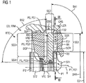
- Figure 1 shows a feedback stage RC of a radial turbo machine RTM, which is designed as a radial turbo compressor CO.
- a radial turbo compressor CO can also be implemented according to the invention, identical in construction, as radial turbo expanders, with a process fluid PF flowing through these components in a radial turbo compressor CO in a first flow direction FD1 and in a radial turbo expander in an opposite, second flow direction FD2.
- the descriptions in this document always refer to the first flow direction FD1, unless otherwise stated.
- Figure 1 shows parts of two successive stages through which flow occurs, a first stage ST1 and a second stage ST2 of a radial turbo machine RTM or radial turbo compressor CO shown in detail, with a return stage RTC between the two stages ST1, ST2 being shown completely schematically.
- the two stages ST1, ST2 are shown here with impellers arranged to be rotatable about the axis of rotation X, a first impeller IP1 and a second impeller IP2.
- a process fluid PF first flows through the first impeller IP1, flowing in axially and flowing out radially along a first flow direction FD1.
- An oppositely oriented second flow direction FD2 is also given as an example, as would be the case with a radial expander.
- the process fluid PF flowing radially outward, reaches a radially outwardly directed first section SG1 and is decelerated there, passes downstream into an approximately 180 ° deflection of a second section SG2 and then into a radially inward one Return of a third section SG3 of the return stage RTC.
- the process fluid PF reaches the second impeller IP2 in a fourth section SG4, flowing radially inward, deflected in an axially flowing direction, in order to be accelerated radially outward there again.
- the return stage RTC comprises a blade bottom RR, guide blades VNS and an intermediate bottom DGP.
- the intermediate floor DGP is supported by at least one support SUP in a support device - here in a housing CAS - and positioned there.
- the support SUP and the supporting section of the housing CAS are designed as a tongue and groove connection in a form-fitting manner.
- the return stage has RTC or the blade bottom RR and the intermediate bottom DGP has a joint that runs in a common plane essentially along the X axis.
- This parting line is conveniently located in the same parting line as a parting line, not shown, of the CAS housing.
- the rotor is designed to be divisible between two impellers or the impellers are designed to be axially displaceable in relation to one another for the purpose of assembly, so that the return stages RTC can be designed undivided and gradually assembled together with the impellers IP1, IP2 of the rotor before merging with a surrounding housing takes place.
- the housing CAS can in any case be designed to be divided horizontally or vertically.
- the conventional design of the return stage RTC which is in the Figure 1 is shown, provides that the blade base RR, the guide vanes VNS and the intermediate base DGP are attached to one another. In the present case, this is done using SCR screws, which are shown in simplified form by means of dash-dotted lines. So that the screws SCR on the one hand adequately fasten the blade bottom RR to the intermediate bottom DGP and must therefore have a minimum thickness, on the other hand a sufficiently large through-hole must be provided in the guide vanes VNS so that the profile of the guide vanes VNS must be sufficiently strong.
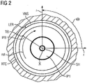
- FIG Figure 2 shows schematically a cross section through a radial turbine machine RTM according to the invention, as shown in FIG Figure 1 is shown with II-II.
- the one mounted on the SH shaft The first impeller IP1 is mounted so that it can rotate about the axis X along the direction of rotation ROT. The directions radially, horizontally and vertically are drawn as an example.
- the circumferential position angle 8 runs positively against the direction of rotation ROT.
- the first impeller IP1 has moving blades IPB of a moving blade stage, shown as an example.
- the trailing edge TEI is entered for a rotor blade IPB.
- the return stage RTC extends downstream of the first impeller IP1.
- the return stage RTC has a guide vane stage VST with guide vanes VNS, one of which is shown as an example.
- the guide vane VNS shown schematically is only shown with its leading edge LER.
- Overall shows the Figure 2 the relationship between the direction of rotation ROT of the shaft SH or the running wheels IP1, IP2 and the circumferential position angle ⁇ .
- Figure 3 shows three-dimensional parts of the return stage RTC, namely the guide vane stage VST with the guide vanes VNS and their three-dimensional design.
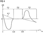
- the Figure 4 shows the course of the difference between the circumferential position angle of the outer track to the inner track plotted over the profile center line coordinate L, which is specified normalized to an entire length l.
- a first alternative ALT1 provides that the difference is initially positive and then drops to 0 at approx. 0.3L and there is constant until it drops into negative at approx. 0.65L ⁇ .
- a second alternative ALT2 provides that the circumferential position angle difference ⁇ is initially positive in the area of the leading edge LER, then drops into the negative, has a local minimum there and rises again up to a difference of 0 at around 0.3L. There, ⁇ remains constant up to about 0.65L and then rises to the positive, up to a local maximum, and then falls back to the negative.
Landscapes
- Engineering & Computer Science (AREA)
- Mechanical Engineering (AREA)
- General Engineering & Computer Science (AREA)
- Structures Of Non-Positive Displacement Pumps (AREA)
Claims (9)
- Passage ( RTC ) de retour pour la traversée au moyen d'un fluide de processus suivant une direction de traversée d'une turbomachine ( RTM ) radiale, notamment passage ( RCC ) de retour d'un turbocompresseur radial,
dans lequel le passage ( RTC ) de retour s'étend annulairement autour d'un axe ( X ),
dans lequel le passage ( RTC ) de retour est défini vers l'intérieur radialement par un contour ( IDC ) limite intérieur et vers l'extérieur radialement par un contour ( ODC ) limite extérieur,
dans lequel, suivant une première direction ( FD1 ) de traversée, le passage ( RTC ) de retour s'étend vers l'extérieur radialement suivant un premier tronçon ( SG1 ), dans lequel le passage ( RTC ) de retour s'étend de l'extérieur radialement vers l'intérieur radialement dans un deuxième tronçon ( SG2 ) suivant la première direction ( FD1 ) de traversée en décrivant une déviation en forme d'arc,
dans lequel le passage ( RTC ) de retour s'étend de l'extérieur radialement vers l'intérieur radialement suivant la première direction ( FD1 ) de traversée dans un troisième tronçon ( SG3 ),
dans lequel le passage ( RTC ) de retour s'étend de l'intérieur radialement vers l'axe suivant la première direction ( FD1 ) de traversée dans un quatrième tronçon ( SG4 ), en décrivant une déviation en forme d'arc,
dans lequel au moins un étage ( VST ) d'aubes directrices, comprenant des aubes ( VNS ) directrices, s'étend au moins suivant une partie du troisième tronçon ( SG3 ) et segmente le passage de retour dans la direction périphérique en des canaux d'écoulement,- dans lequel, respectivement, une ligne ( PML ) médiane de profil d'une section ( PRC ) transversale de profil des aubes ( VNS ) directrices de l'étage ( VST ) d'aubes directrices définit, du côté du contour ( IDC ) limite intérieur, une piste ( ITR ) intérieure et, du côté du contour ( ODC ) limite extérieur, une piste ( OTR ) extérieure,- dans lequel les tracés de la piste ( ITR ) intérieure et de la piste ( OTR ) extérieure peuvent être définis par :dans lequel les aubes ( VNS ) directrices ont, suivant la première direction ( FD1 ) de traversée, trois tronçons de profil successifs :
 θ : angle de position périphérique dans le sens de rotation de la turbomachine (RTM) radiale à sommet sur l'axe (X),L : coordonnée courante de ligne médiane de profil suivant la première direction (FD1) de traversée suivant une hauteur médiane de l'aube (VNS) directrice respective normée sur une longueur totale 1,Fe( L ) :dépendance fonctionnelle entre l'angle θ de position périphérique et la position L sur la ligne médiane de profil,R : rayon de la position de la piste ( ITR ) intérieure ou de la piste ( OTR ) extérieure,un premier tronçon ( PS1 ) de profil,un deuxième tronçon ( PS2 ) de profil,un troisième tronçon ( PS3 ) de profil,caractérisé
en ce que, respectivement, pour des valeurs de L dans les tronçons de profil, on a :dans le premier tronçon ( PS1 ) de profil : dans le deuxième tronçon ( PS2 ) de profil :
 dans le troisième tronçon ( PS2 ) de profil :
- Passage ( RTC ) de retour suivant la revendication 1, dans lequel, dans le premier ( PS1 ) de profil, on a :


- Passage ( RTC ) de retour suivant la revendication 1 ou 2, dans lequel on a :


- Passage ( RTC ) de retour suivant la revendication 1, 2 ou 3,
dans lequel le deuxième tronçon ( PS2 ) de profil s'étend d'au plus L=0,4 à au moins L=0,6. - Passage ( RTC ) de retour suivant la revendication 1, 2, 3 ou 4,
dans lequel au moins certaines des aubes ( VNS ) directrices dans le deuxième tronçon ( PS2 ) de profil ont, pour le passage d'un élément de fixation entre le contour ( IDC ) limite intérieur et le contour ( ODC ) limite extérieur, un évidement s'étendant d'un point de la piste intérieure à un point de la piste extérieure. - Passage ( RTC ) de retour suivant la revendication 1, 2, 3, 4 ou 5,
dans lequel les aubes ( VNS ) directrices sont disposées chacune en ayant un bord ( LER ) d'entrée, respectivement dans le deuxième tronçon ( SG2 ), de préférence dans une région de la déviation en forme d'arc du deuxième tronçon ( SG2 ) entre 0° -90° d'un premier angle ( BA1 ) de déviation. - Passage ( RTC ) de retour suivant la revendication 1, 2, 3, 4, 5 ou 6,
dans lequel les aubes ( VNS ) directrices sont disposées chacune en ayant un bord ( VTE ) de sortie, respectivement dans le quatrième tronçon ( SG4 ), de préférence dans une région de la déviation en forme d'arc du quatrième tronçon ( SG4 ) entre 0° -60° d'un deuxième angle ( BA2 ) de déviation. - Turbomachine ( RTM ) radiale, notamment turbocompresseur radial, comprenant au moins un passage ( RTC ) de retour suivant la revendication 1, 2, 3, 4, 5, 6 ou 7, dans laquelle la turbomachine ( RTM ) radiale a un rotor ( ROT ) monté tournant autour de l'axe ( X ) et comprenant au moins deux roues ( IP1, IP2 ), le passage ( RTC ) de retour conduisant le courant suivant la première direction ( FD1 ) de passage d'une roue ( IP1, IP2 ) à une roue ( IP1, IP2 ) en aval.
- Turbomachine ( RTM ) radiale suivant la revendication 8, dans laquelle les roues ( IP1, IP2 ) ont, en amont du passage ( RTC ) de retour, un diamètre ( D2 ) de sortie, la section transversale de transition du passage de retour du premier tronçon ( SG1 ) au deuxième tronçon ( SG2 ) étant disposée sur un diamètre ( DRR ) intermédiaire, dans lequel on a :
DRR/D2 < 1,5, notamment DRR/D2 < 1,4
en ayant :D2 : diamètre extérieur des roues ( IP1, IP2 )DRR : diamètre intermédiaire de la section transversale de transition du passage de retour du premier tronçon ( SGI ) au deuxième tronçon ( SG2 ).
Applications Claiming Priority (2)
| Application Number | Priority Date | Filing Date | Title |
|---|---|---|---|
| EP17155607.9A EP3361101A1 (fr) | 2017-02-10 | 2017-02-10 | Canal de retour de compresseur ou turbodétendeur multicellulaire avec aubes directrices vrillées |
| PCT/EP2018/050397 WO2018145838A1 (fr) | 2017-02-10 | 2018-01-09 | Étage de retour d'un compresseur à étages multiples ou détendeur doté d'aubes directrices vrillées |
Publications (2)
| Publication Number | Publication Date |
|---|---|
| EP3551889A1 EP3551889A1 (fr) | 2019-10-16 |
| EP3551889B1 true EP3551889B1 (fr) | 2020-08-19 |
Family
ID=58043888
Family Applications (2)
| Application Number | Title | Priority Date | Filing Date |
|---|---|---|---|
| EP17155607.9A Withdrawn EP3361101A1 (fr) | 2017-02-10 | 2017-02-10 | Canal de retour de compresseur ou turbodétendeur multicellulaire avec aubes directrices vrillées |
| EP18702076.3A Active EP3551889B1 (fr) | 2017-02-10 | 2018-01-09 | Canal de retour de compresseur ou turbodétendeur multicellulaire avec aubes directrices vrillées |
Family Applications Before (1)
| Application Number | Title | Priority Date | Filing Date |
|---|---|---|---|
| EP17155607.9A Withdrawn EP3361101A1 (fr) | 2017-02-10 | 2017-02-10 | Canal de retour de compresseur ou turbodétendeur multicellulaire avec aubes directrices vrillées |
Country Status (4)
| Country | Link |
|---|---|
| US (1) | US11073162B2 (fr) |
| EP (2) | EP3361101A1 (fr) |
| CN (1) | CN110291295B (fr) |
| WO (1) | WO2018145838A1 (fr) |
Families Citing this family (6)
| Publication number | Priority date | Publication date | Assignee | Title |
|---|---|---|---|---|
| US10760587B2 (en) | 2017-06-06 | 2020-09-01 | Elliott Company | Extended sculpted twisted return channel vane arrangement |
| KR102427392B1 (ko) * | 2018-01-24 | 2022-07-29 | 한화에어로스페이스 주식회사 | 압축기용 디퓨저 |
| EP3690254A1 (fr) | 2019-01-31 | 2020-08-05 | Siemens Aktiengesellschaft | Roue à aubes d'une turbomachine radiale, turbomachine radiale |
| US11598347B2 (en) * | 2019-06-28 | 2023-03-07 | Trane International Inc. | Impeller with external blades |
| JP2022184085A (ja) * | 2021-05-31 | 2022-12-13 | 三菱重工コンプレッサ株式会社 | 遠心圧縮機 |
| CN114593089A (zh) * | 2022-01-26 | 2022-06-07 | 北京盈天航空动力科技有限公司 | 一种微小型涡喷发动机v型子午流道扩压器 |
Family Cites Families (16)
| Publication number | Priority date | Publication date | Assignee | Title |
|---|---|---|---|---|
| DE1403497A1 (de) * | 1961-11-03 | 1969-01-23 | Doelz Dipl Ing Heinrich | Mehrstufiger Turbokompressor |
| CS175720B1 (fr) * | 1974-04-01 | 1977-05-31 | ||
| JPS562499A (en) * | 1979-06-22 | 1981-01-12 | Hitachi Ltd | Guide vane for multistage oblique flow pump |
| JPS5641496A (en) * | 1979-09-12 | 1981-04-18 | Hitachi Ltd | Return bend of single shaft multistage centrifugal compressor |
| CA1252075A (fr) | 1983-09-22 | 1989-04-04 | Dresser Industries, Inc. | Configuration de diffuseur pour compresseur centrifuge |
| DE4234739C1 (de) | 1992-10-15 | 1993-11-25 | Gutehoffnungshuette Man | Getriebe-Mehrwellenturbokompressor mit Rückführstufen |
| JPH10331793A (ja) | 1997-06-03 | 1998-12-15 | Mitsubishi Heavy Ind Ltd | 遠心圧縮機の戻り流路構造 |
| JPH11173299A (ja) | 1997-12-05 | 1999-06-29 | Mitsubishi Heavy Ind Ltd | 遠心圧縮機 |
| JP2004150404A (ja) * | 2002-11-01 | 2004-05-27 | Mitsubishi Heavy Ind Ltd | ベーンドディフューザ及び該ディフューザを備えた輻流ターボ機械 |
| US7448852B2 (en) | 2005-08-09 | 2008-11-11 | Praxair Technology, Inc. | Leaned centrifugal compressor airfoil diffuser |
| US7717672B2 (en) * | 2006-08-29 | 2010-05-18 | Honeywell International Inc. | Radial vaned diffusion system with integral service routings |
| DE102009019061A1 (de) | 2009-04-27 | 2010-10-28 | Man Diesel & Turbo Se | Mehrstufiger Radialverdichter |
| JP2012102712A (ja) * | 2010-11-15 | 2012-05-31 | Mitsubishi Heavy Ind Ltd | ターボ型圧縮機械 |
| ITCO20120055A1 (it) * | 2012-11-06 | 2014-05-07 | Nuovo Pignone Srl | Pala di canale di ritorno per compressori centrifughi |
| DE102014203251A1 (de) | 2014-02-24 | 2015-08-27 | Siemens Aktiengesellschaft | Rückführstufe für eine Radialturbomaschine |
| CN104121203A (zh) * | 2014-07-14 | 2014-10-29 | 杨丽萍 | 一种污水用分段式多级泵的单段结构 |
-
2017
- 2017-02-10 EP EP17155607.9A patent/EP3361101A1/fr not_active Withdrawn
-
2018
- 2018-01-09 CN CN201880011227.2A patent/CN110291295B/zh active Active
- 2018-01-09 US US16/483,424 patent/US11073162B2/en active Active
- 2018-01-09 WO PCT/EP2018/050397 patent/WO2018145838A1/fr active Search and Examination
- 2018-01-09 EP EP18702076.3A patent/EP3551889B1/fr active Active
Non-Patent Citations (1)
| Title |
|---|
| None * |
Also Published As
| Publication number | Publication date |
|---|---|
| EP3361101A1 (fr) | 2018-08-15 |
| WO2018145838A1 (fr) | 2018-08-16 |
| CN110291295A (zh) | 2019-09-27 |
| US11073162B2 (en) | 2021-07-27 |
| CN110291295B (zh) | 2020-11-03 |
| EP3551889A1 (fr) | 2019-10-16 |
| US20200011345A1 (en) | 2020-01-09 |
Similar Documents
| Publication | Publication Date | Title |
|---|---|---|
| EP3551889B1 (fr) | Canal de retour de compresseur ou turbodétendeur multicellulaire avec aubes directrices vrillées | |
| EP3551890B1 (fr) | Etage de retour | |
| EP2881548B1 (fr) | Compresseur de turbine à gaz | |
| EP0690206A2 (fr) | Diffuseur pour une turbomachine | |
| EP2947270B1 (fr) | Groupe de série d'aubes | |
| WO2008122507A1 (fr) | Agencement en feuillure | |
| EP2505851B1 (fr) | Aubage de stator pour un compresseur axial dans une turbomachine | |
| EP3205883A1 (fr) | Roue pour un turbocompresseur centrifuge | |
| EP3568597B1 (fr) | Étage de recirculation et turbomachine à énergie fluidique radiale | |
| EP3225781A2 (fr) | Canal d'aube, grille d'aube et turbomachine | |
| DE102020201830B4 (de) | Leitschaufel-diffusor und zentrifugalkompressor | |
| DE112015006062T5 (de) | Turbine | |
| DE102004042295A1 (de) | Rotor für ein Triebwerk | |
| EP2826957A1 (fr) | Rotor pour une turbomachine thermique | |
| EP3390832B1 (fr) | Étage de retour d'une turbomachine à énergie fluidique radiale | |
| EP3181813B1 (fr) | Filetage centré d'aubes | |
| EP2458149A1 (fr) | Aubage pour turboréacteur | |
| DE112017001298T5 (de) | Mehrstufenaxialkompressor und Gasturbine | |
| DE102016208265A1 (de) | Rückführstufe, Radialturboverdichter | |
| EP3498972A1 (fr) | Module de turbine pour une turbomachine | |
| DE112014003154T5 (de) | Spiralstruktur und Lader | |
| DE102019109023B3 (de) | Verdichterlaufrad mit wechselnder Beschaufelung | |
| EP3404211A1 (fr) | Segment de grille d'aubes d'une turbine avec paroi de plateforme contourée, grille d'aubes, canal d'aube, plateforme, turbine et moteur d'aéronef associés | |
| WO2016096420A1 (fr) | Système de refroidissement pour turbomachines | |
| EP3954875B1 (fr) | Aube directrice, étage de compresseur pour une turbine à gaz, turbomachine et procédé pour exploiter une turbomachine |
Legal Events
| Date | Code | Title | Description |
|---|---|---|---|
| STAA | Information on the status of an ep patent application or granted ep patent |
Free format text: STATUS: UNKNOWN |
|
| STAA | Information on the status of an ep patent application or granted ep patent |
Free format text: STATUS: THE INTERNATIONAL PUBLICATION HAS BEEN MADE |
|
| PUAI | Public reference made under article 153(3) epc to a published international application that has entered the european phase |
Free format text: ORIGINAL CODE: 0009012 |
|
| STAA | Information on the status of an ep patent application or granted ep patent |
Free format text: STATUS: REQUEST FOR EXAMINATION WAS MADE |
|
| 17P | Request for examination filed |
Effective date: 20190710 |
|
| AK | Designated contracting states |
Kind code of ref document: A1 Designated state(s): AL AT BE BG CH CY CZ DE DK EE ES FI FR GB GR HR HU IE IS IT LI LT LU LV MC MK MT NL NO PL PT RO RS SE SI SK SM TR |
|
| GRAP | Despatch of communication of intention to grant a patent |
Free format text: ORIGINAL CODE: EPIDOSNIGR1 |
|
| STAA | Information on the status of an ep patent application or granted ep patent |
Free format text: STATUS: GRANT OF PATENT IS INTENDED |
|
| INTG | Intention to grant announced |
Effective date: 20200420 |
|
| GRAS | Grant fee paid |
Free format text: ORIGINAL CODE: EPIDOSNIGR3 |
|
| GRAA | (expected) grant |
Free format text: ORIGINAL CODE: 0009210 |
|
| STAA | Information on the status of an ep patent application or granted ep patent |
Free format text: STATUS: THE PATENT HAS BEEN GRANTED |
|
| AK | Designated contracting states |
Kind code of ref document: B1 Designated state(s): AL AT BE BG CH CY CZ DE DK EE ES FI FR GB GR HR HU IE IS IT LI LT LU LV MC MK MT NL NO PL PT RO RS SE SI SK SM TR |
|
| REG | Reference to a national code |
Ref country code: CH Ref legal event code: EP |
|
| REG | Reference to a national code |
Ref country code: DE Ref legal event code: R096 Ref document number: 502018002243 Country of ref document: DE |
|
| REG | Reference to a national code |
Ref country code: AT Ref legal event code: REF Ref document number: 1304232 Country of ref document: AT Kind code of ref document: T Effective date: 20200915 |
|
| REG | Reference to a national code |
Ref country code: IE Ref legal event code: FG4D Free format text: LANGUAGE OF EP DOCUMENT: GERMAN |
|
| REG | Reference to a national code |
Ref country code: CH Ref legal event code: NV Representative=s name: SIEMENS SCHWEIZ AG, CH |
|
| REG | Reference to a national code |
Ref country code: DE Ref legal event code: R081 Ref document number: 502018002243 Country of ref document: DE Owner name: SIEMENS ENERGY GLOBAL GMBH & CO. KG, DE Free format text: FORMER OWNER: SIEMENS AKTIENGESELLSCHAFT, 80333 MUENCHEN, DE |
|
| REG | Reference to a national code |
Ref country code: LT Ref legal event code: MG4D |
|
| RAP2 | Party data changed (patent owner data changed or rights of a patent transferred) |
Owner name: SIEMENS ENERGY GLOBAL GMBH & CO. KG |
|
| REG | Reference to a national code |
Ref country code: NL Ref legal event code: MP Effective date: 20200819 |
|
| PG25 | Lapsed in a contracting state [announced via postgrant information from national office to epo] |
Ref country code: LT Free format text: LAPSE BECAUSE OF FAILURE TO SUBMIT A TRANSLATION OF THE DESCRIPTION OR TO PAY THE FEE WITHIN THE PRESCRIBED TIME-LIMIT Effective date: 20200819 Ref country code: HR Free format text: LAPSE BECAUSE OF FAILURE TO SUBMIT A TRANSLATION OF THE DESCRIPTION OR TO PAY THE FEE WITHIN THE PRESCRIBED TIME-LIMIT Effective date: 20200819 Ref country code: GR Free format text: LAPSE BECAUSE OF FAILURE TO SUBMIT A TRANSLATION OF THE DESCRIPTION OR TO PAY THE FEE WITHIN THE PRESCRIBED TIME-LIMIT Effective date: 20201120 Ref country code: FI Free format text: LAPSE BECAUSE OF FAILURE TO SUBMIT A TRANSLATION OF THE DESCRIPTION OR TO PAY THE FEE WITHIN THE PRESCRIBED TIME-LIMIT Effective date: 20200819 Ref country code: PT Free format text: LAPSE BECAUSE OF FAILURE TO SUBMIT A TRANSLATION OF THE DESCRIPTION OR TO PAY THE FEE WITHIN THE PRESCRIBED TIME-LIMIT Effective date: 20201221 Ref country code: BG Free format text: LAPSE BECAUSE OF FAILURE TO SUBMIT A TRANSLATION OF THE DESCRIPTION OR TO PAY THE FEE WITHIN THE PRESCRIBED TIME-LIMIT Effective date: 20201119 Ref country code: SE Free format text: LAPSE BECAUSE OF FAILURE TO SUBMIT A TRANSLATION OF THE DESCRIPTION OR TO PAY THE FEE WITHIN THE PRESCRIBED TIME-LIMIT Effective date: 20200819 Ref country code: NO Free format text: LAPSE BECAUSE OF FAILURE TO SUBMIT A TRANSLATION OF THE DESCRIPTION OR TO PAY THE FEE WITHIN THE PRESCRIBED TIME-LIMIT Effective date: 20201119 |
|
| PG25 | Lapsed in a contracting state [announced via postgrant information from national office to epo] |
Ref country code: IS Free format text: LAPSE BECAUSE OF FAILURE TO SUBMIT A TRANSLATION OF THE DESCRIPTION OR TO PAY THE FEE WITHIN THE PRESCRIBED TIME-LIMIT Effective date: 20201219 Ref country code: NL Free format text: LAPSE BECAUSE OF FAILURE TO SUBMIT A TRANSLATION OF THE DESCRIPTION OR TO PAY THE FEE WITHIN THE PRESCRIBED TIME-LIMIT Effective date: 20200819 Ref country code: RS Free format text: LAPSE BECAUSE OF FAILURE TO SUBMIT A TRANSLATION OF THE DESCRIPTION OR TO PAY THE FEE WITHIN THE PRESCRIBED TIME-LIMIT Effective date: 20200819 Ref country code: PL Free format text: LAPSE BECAUSE OF FAILURE TO SUBMIT A TRANSLATION OF THE DESCRIPTION OR TO PAY THE FEE WITHIN THE PRESCRIBED TIME-LIMIT Effective date: 20200819 Ref country code: LV Free format text: LAPSE BECAUSE OF FAILURE TO SUBMIT A TRANSLATION OF THE DESCRIPTION OR TO PAY THE FEE WITHIN THE PRESCRIBED TIME-LIMIT Effective date: 20200819 |
|
| PG25 | Lapsed in a contracting state [announced via postgrant information from national office to epo] |
Ref country code: DK Free format text: LAPSE BECAUSE OF FAILURE TO SUBMIT A TRANSLATION OF THE DESCRIPTION OR TO PAY THE FEE WITHIN THE PRESCRIBED TIME-LIMIT Effective date: 20200819 Ref country code: CZ Free format text: LAPSE BECAUSE OF FAILURE TO SUBMIT A TRANSLATION OF THE DESCRIPTION OR TO PAY THE FEE WITHIN THE PRESCRIBED TIME-LIMIT Effective date: 20200819 Ref country code: RO Free format text: LAPSE BECAUSE OF FAILURE TO SUBMIT A TRANSLATION OF THE DESCRIPTION OR TO PAY THE FEE WITHIN THE PRESCRIBED TIME-LIMIT Effective date: 20200819 Ref country code: EE Free format text: LAPSE BECAUSE OF FAILURE TO SUBMIT A TRANSLATION OF THE DESCRIPTION OR TO PAY THE FEE WITHIN THE PRESCRIBED TIME-LIMIT Effective date: 20200819 Ref country code: SM Free format text: LAPSE BECAUSE OF FAILURE TO SUBMIT A TRANSLATION OF THE DESCRIPTION OR TO PAY THE FEE WITHIN THE PRESCRIBED TIME-LIMIT Effective date: 20200819 |
|
| REG | Reference to a national code |
Ref country code: DE Ref legal event code: R097 Ref document number: 502018002243 Country of ref document: DE |
|
| PG25 | Lapsed in a contracting state [announced via postgrant information from national office to epo] |
Ref country code: AL Free format text: LAPSE BECAUSE OF FAILURE TO SUBMIT A TRANSLATION OF THE DESCRIPTION OR TO PAY THE FEE WITHIN THE PRESCRIBED TIME-LIMIT Effective date: 20200819 Ref country code: ES Free format text: LAPSE BECAUSE OF FAILURE TO SUBMIT A TRANSLATION OF THE DESCRIPTION OR TO PAY THE FEE WITHIN THE PRESCRIBED TIME-LIMIT Effective date: 20200819 |
|
| PLBE | No opposition filed within time limit |
Free format text: ORIGINAL CODE: 0009261 |
|
| STAA | Information on the status of an ep patent application or granted ep patent |
Free format text: STATUS: NO OPPOSITION FILED WITHIN TIME LIMIT |
|
| PG25 | Lapsed in a contracting state [announced via postgrant information from national office to epo] |
Ref country code: SK Free format text: LAPSE BECAUSE OF FAILURE TO SUBMIT A TRANSLATION OF THE DESCRIPTION OR TO PAY THE FEE WITHIN THE PRESCRIBED TIME-LIMIT Effective date: 20200819 |
|
| 26N | No opposition filed |
Effective date: 20210520 |
|
| PG25 | Lapsed in a contracting state [announced via postgrant information from national office to epo] |
Ref country code: SI Free format text: LAPSE BECAUSE OF FAILURE TO SUBMIT A TRANSLATION OF THE DESCRIPTION OR TO PAY THE FEE WITHIN THE PRESCRIBED TIME-LIMIT Effective date: 20200819 Ref country code: MC Free format text: LAPSE BECAUSE OF FAILURE TO SUBMIT A TRANSLATION OF THE DESCRIPTION OR TO PAY THE FEE WITHIN THE PRESCRIBED TIME-LIMIT Effective date: 20200819 |
|
| PG25 | Lapsed in a contracting state [announced via postgrant information from national office to epo] |
Ref country code: LU Free format text: LAPSE BECAUSE OF NON-PAYMENT OF DUE FEES Effective date: 20210109 |
|
| REG | Reference to a national code |
Ref country code: BE Ref legal event code: MM Effective date: 20210131 |
|
| PG25 | Lapsed in a contracting state [announced via postgrant information from national office to epo] |
Ref country code: IE Free format text: LAPSE BECAUSE OF NON-PAYMENT OF DUE FEES Effective date: 20210109 |
|
| PG25 | Lapsed in a contracting state [announced via postgrant information from national office to epo] |
Ref country code: BE Free format text: LAPSE BECAUSE OF NON-PAYMENT OF DUE FEES Effective date: 20210131 |
|
| GBPC | Gb: european patent ceased through non-payment of renewal fee |
Effective date: 20220109 |
|
| PG25 | Lapsed in a contracting state [announced via postgrant information from national office to epo] |
Ref country code: GB Free format text: LAPSE BECAUSE OF NON-PAYMENT OF DUE FEES Effective date: 20220109 |
|
| PG25 | Lapsed in a contracting state [announced via postgrant information from national office to epo] |
Ref country code: CY Free format text: LAPSE BECAUSE OF FAILURE TO SUBMIT A TRANSLATION OF THE DESCRIPTION OR TO PAY THE FEE WITHIN THE PRESCRIBED TIME-LIMIT Effective date: 20200819 |
|
| PG25 | Lapsed in a contracting state [announced via postgrant information from national office to epo] |
Ref country code: HU Free format text: LAPSE BECAUSE OF FAILURE TO SUBMIT A TRANSLATION OF THE DESCRIPTION OR TO PAY THE FEE WITHIN THE PRESCRIBED TIME-LIMIT; INVALID AB INITIO Effective date: 20180109 |
|
| REG | Reference to a national code |
Ref country code: AT Ref legal event code: MM01 Ref document number: 1304232 Country of ref document: AT Kind code of ref document: T Effective date: 20230109 |
|
| PG25 | Lapsed in a contracting state [announced via postgrant information from national office to epo] |
Ref country code: AT Free format text: LAPSE BECAUSE OF NON-PAYMENT OF DUE FEES Effective date: 20230109 |
|
| PG25 | Lapsed in a contracting state [announced via postgrant information from national office to epo] |
Ref country code: MK Free format text: LAPSE BECAUSE OF FAILURE TO SUBMIT A TRANSLATION OF THE DESCRIPTION OR TO PAY THE FEE WITHIN THE PRESCRIBED TIME-LIMIT Effective date: 20200819 Ref country code: AT Free format text: LAPSE BECAUSE OF NON-PAYMENT OF DUE FEES Effective date: 20230109 |
|
| PGFP | Annual fee paid to national office [announced via postgrant information from national office to epo] |
Ref country code: DE Payment date: 20240129 Year of fee payment: 7 Ref country code: CH Payment date: 20240202 Year of fee payment: 7 |
|
| PGFP | Annual fee paid to national office [announced via postgrant information from national office to epo] |
Ref country code: IT Payment date: 20240123 Year of fee payment: 7 Ref country code: FR Payment date: 20240125 Year of fee payment: 7 |