EP2881202B1 - Schneidekanteneinstellungsvorrichtung - Google Patents
Schneidekanteneinstellungsvorrichtung Download PDFInfo
- Publication number
- EP2881202B1 EP2881202B1 EP13827937.7A EP13827937A EP2881202B1 EP 2881202 B1 EP2881202 B1 EP 2881202B1 EP 13827937 A EP13827937 A EP 13827937A EP 2881202 B1 EP2881202 B1 EP 2881202B1
- Authority
- EP
- European Patent Office
- Prior art keywords
- rotary member
- cutting edge
- cartridge
- substantially cylindrical
- adjustment device
- Prior art date
- Legal status (The legal status is an assumption and is not a legal conclusion. Google has not performed a legal analysis and makes no representation as to the accuracy of the status listed.)
- Active
Links
Images


Classifications
-
- B—PERFORMING OPERATIONS; TRANSPORTING
- B23—MACHINE TOOLS; METAL-WORKING NOT OTHERWISE PROVIDED FOR
- B23C—MILLING
- B23C5/00—Milling-cutters
- B23C5/16—Milling-cutters characterised by physical features other than shape
- B23C5/20—Milling-cutters characterised by physical features other than shape with removable cutter bits or teeth or cutting inserts
- B23C5/22—Securing arrangements for bits or teeth or cutting inserts
- B23C5/2204—Securing arrangements for bits or teeth or cutting inserts with cutting inserts clamped against the walls of the recess in the cutter body by a clamping member acting upon the wall of a hole in the insert
- B23C5/2226—Securing arrangements for bits or teeth or cutting inserts with cutting inserts clamped against the walls of the recess in the cutter body by a clamping member acting upon the wall of a hole in the insert for plate-like cutting inserts fitted on an intermediate carrier, e.g. shank fixed in the cutter body
-
- B—PERFORMING OPERATIONS; TRANSPORTING
- B23—MACHINE TOOLS; METAL-WORKING NOT OTHERWISE PROVIDED FOR
- B23B—TURNING; BORING
- B23B27/00—Tools for turning or boring machines; Tools of a similar kind in general; Accessories therefor
- B23B27/14—Cutting tools of which the bits or tips or cutting inserts are of special material
- B23B27/16—Cutting tools of which the bits or tips or cutting inserts are of special material with exchangeable cutting bits or cutting inserts, e.g. able to be clamped
- B23B27/1685—Adjustable position of the cutting inserts
- B23B27/1696—Angular position of the cutting insert adjustable around an axis generally perpendicularly to the chip-forming plane
-
- B—PERFORMING OPERATIONS; TRANSPORTING
- B23—MACHINE TOOLS; METAL-WORKING NOT OTHERWISE PROVIDED FOR
- B23B—TURNING; BORING
- B23B29/00—Holders for non-rotary cutting tools; Boring bars or boring heads; Accessories for tool holders
- B23B29/03—Boring heads
- B23B29/034—Boring heads with tools moving radially, e.g. for making chamfers or undercuttings
- B23B29/03403—Boring heads with tools moving radially, e.g. for making chamfers or undercuttings radially adjustable before starting manufacturing
- B23B29/03428—Boring heads with tools moving radially, e.g. for making chamfers or undercuttings radially adjustable before starting manufacturing by means of an eccentric
-
- B—PERFORMING OPERATIONS; TRANSPORTING
- B23—MACHINE TOOLS; METAL-WORKING NOT OTHERWISE PROVIDED FOR
- B23C—MILLING
- B23C5/00—Milling-cutters
- B23C5/16—Milling-cutters characterised by physical features other than shape
- B23C5/20—Milling-cutters characterised by physical features other than shape with removable cutter bits or teeth or cutting inserts
- B23C5/22—Securing arrangements for bits or teeth or cutting inserts
- B23C5/24—Securing arrangements for bits or teeth or cutting inserts adjustable
- B23C5/2479—Securing arrangements for bits or teeth or cutting inserts adjustable the adjusting means being eccentrics
-
- B—PERFORMING OPERATIONS; TRANSPORTING
- B23—MACHINE TOOLS; METAL-WORKING NOT OTHERWISE PROVIDED FOR
- B23B—TURNING; BORING
- B23B2260/00—Details of constructional elements
- B23B2260/004—Adjustable elements
-
- B—PERFORMING OPERATIONS; TRANSPORTING
- B23—MACHINE TOOLS; METAL-WORKING NOT OTHERWISE PROVIDED FOR
- B23B—TURNING; BORING
- B23B2260/00—Details of constructional elements
- B23B2260/02—Cams
-
- B—PERFORMING OPERATIONS; TRANSPORTING
- B23—MACHINE TOOLS; METAL-WORKING NOT OTHERWISE PROVIDED FOR
- B23C—MILLING
- B23C2260/00—Details of constructional elements
- B23C2260/04—Adjustable elements
-
- B—PERFORMING OPERATIONS; TRANSPORTING
- B23—MACHINE TOOLS; METAL-WORKING NOT OTHERWISE PROVIDED FOR
- B23C—MILLING
- B23C2260/00—Details of constructional elements
- B23C2260/12—Cams
-
- Y—GENERAL TAGGING OF NEW TECHNOLOGICAL DEVELOPMENTS; GENERAL TAGGING OF CROSS-SECTIONAL TECHNOLOGIES SPANNING OVER SEVERAL SECTIONS OF THE IPC; TECHNICAL SUBJECTS COVERED BY FORMER USPC CROSS-REFERENCE ART COLLECTIONS [XRACs] AND DIGESTS
- Y10—TECHNICAL SUBJECTS COVERED BY FORMER USPC
- Y10T—TECHNICAL SUBJECTS COVERED BY FORMER US CLASSIFICATION
- Y10T407/00—Cutters, for shaping
- Y10T407/22—Cutters, for shaping including holder having seat for inserted tool
- Y10T407/2222—Tool adjustable relative to holder
- Y10T407/2224—Tool adjustable relative to holder with indicator
-
- Y—GENERAL TAGGING OF NEW TECHNOLOGICAL DEVELOPMENTS; GENERAL TAGGING OF CROSS-SECTIONAL TECHNOLOGIES SPANNING OVER SEVERAL SECTIONS OF THE IPC; TECHNICAL SUBJECTS COVERED BY FORMER USPC CROSS-REFERENCE ART COLLECTIONS [XRACs] AND DIGESTS
- Y10—TECHNICAL SUBJECTS COVERED BY FORMER USPC
- Y10T—TECHNICAL SUBJECTS COVERED BY FORMER US CLASSIFICATION
- Y10T407/00—Cutters, for shaping
- Y10T407/22—Cutters, for shaping including holder having seat for inserted tool
- Y10T407/2222—Tool adjustable relative to holder
- Y10T407/2244—Tool adjustable relative to holder by movement of seat relative to holder
-
- Y—GENERAL TAGGING OF NEW TECHNOLOGICAL DEVELOPMENTS; GENERAL TAGGING OF CROSS-SECTIONAL TECHNOLOGIES SPANNING OVER SEVERAL SECTIONS OF THE IPC; TECHNICAL SUBJECTS COVERED BY FORMER USPC CROSS-REFERENCE ART COLLECTIONS [XRACs] AND DIGESTS
- Y10—TECHNICAL SUBJECTS COVERED BY FORMER USPC
- Y10T—TECHNICAL SUBJECTS COVERED BY FORMER US CLASSIFICATION
- Y10T407/00—Cutters, for shaping
- Y10T407/22—Cutters, for shaping including holder having seat for inserted tool
- Y10T407/2222—Tool adjustable relative to holder
- Y10T407/2252—Rectilinearly
- Y10T407/2254—Rectilinearly including rotatable cam clamp element
Definitions
- the present invention relates to a cutting edge adjustment device in accordance with the preambles of claims 1, 11 and 12.
- An example of such a cutting edge adjustment device is disclosed by DE 44 07 270 C1 .
- Cutting edge adjustment devices for finely adjusting the position of a cutting edge of a cutting insert in the field of an indexable cutting tool in the related art.
- Cutting edge adjustment devices are mainly used for regularly aligning the positions of cutting edges of a plurality of cutting inserts in a milling tool, respectively.
- a cutting edge adjustment device is used when the projection amount of a cutting edge from a tool body is desirably adjusted also in a turning tool or a drilling tool.
- Patent Literature 1 exemplarily discloses several embodiments of a cutting edge adjustment device by the use of a cam.
- This cutting edge adjustment device basically includes two cam faces abutting against a cutting insert to be mounted on a tool body (i.e., a milling cutter body) and a wedge for fixing the cutting insert to the tool body. The rotation of the cam causes the cutting insert to be directly pressed, thus adjusting the position of a cutting edge of the cutting insert.
- the typical cutting edge adjustment device using the cam as disclosed in Patent Literature 1 does not take the relationship between the rotational amount of the cam and the movement amount of the cutting edge into consideration. As a consequence, it is difficult for an operator to move the cutting edge by a required distance in association with a cam rotating operation in the typical cutting edge adjustment device, thereby raising problems of the difficulty in accurately adjusting the position of the cutting edge, and further, much time required for adjusting the position.
- an object of the present invention is to use a rotary member such as a cam so as to facilitate the quick adjustment of the position of a cutting edge with high accuracy.
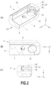
- a cutting edge adjustment device 1 in the present embodiment basically has the configuration in which a cartridge 3 having a cutting insert 4 detachably attached thereto and a rotary member 5 having a cam face are arranged adjacently to each other in a tool body 2. Only a section of the tool body 2 having the cutting edge adjustment device 1 mounted thereon is shown in Fig. 1 .
- the cutting edge adjustment device 1 in the present embodiment is applicable to various cutting tools inclusive of a turning tool, a milling tool, and a drilling tool.
- the cutting edge adjustment device 1 including the tool body 2 in the present embodiment is generally formed into a substantially rectangular parallelepiped. It is to be understood that the tool body 2 or the cutting edge adjustment device 1 should be formed into any appropriate forms and shapes according to a cutting tool, to which the cutting edge adjustment device 1 is applied.
- an end at which the cutting insert 4 is mounted is referred to as a distal end whereas an end opposite to the distal end is referred to as a proximal end.
- an axis parallel to a direction from the proximal end to the distal end is defined as an X axis
- two axes perpendicular to the X axis are defined as a Y axis and a Z axis.
- the cutting edge adjustment device 1 in the present embodiment is assumed to have a largest dimension in the X-axial direction. The cartridge 3 is moved in the X-axial direction, thereby adjusting a cutting edge, that is, adjusting the position of the cutting insert 4.
- the tool body 2 has a recess 6 so as to securely contain the cartridge 3 and the rotary member 5 therein.
- the recess 6 is formed from the distal end to the proximal end of the tool body 2 over a predetermined distance, and further, it is defined by a side surface 10 extending in parallel to an X-Z plane and another side surface 11 on the proximal end side extending in parallel to a Y-Z plane perpendicular to the X-Z plane.
- a side surface extending in parallel to the X-Z plane inclusive of the side surface 10 of the recess 6 may be referred to as a longitudinal side surface whereas a side surface extending in parallel to the Y-Z plane perpendicular to the longitudinal side surface inclusive of the side surface 11 of the recess 6 may be referred to as a lateral side surface.
- a bottom 7 of the recess 6 is a substantially flat plane extending in parallel to an X-Y plane, and has a screw hole 8 at almost the center thereof.
- the screw hole 8 is adapted to receive a fixing screw 9 for fixing the cartridge 3 to the tool body 2.
- the screw hole 8 is formed in a direction substantially perpendicular to the movement direction of the cartridge 3 parallel to the X axis (i.e., the positional adjustment direction of the cutting insert 4) with an inclination with respect to the bottom 7.
- the back of the screw hole is formed in such a manner as to be deflected toward the longitudinal side surface 10 of the recess 6.
- a rotary member holding hole 12 that is formed into a substantially elongated or elliptical shape adjacently to the lateral side surface 11 of the recess 6 and is adapted to allow rotation on a rotary center axis in a Z-axial direction of the rotary member 5 and movement in an X-axial direction while holding the rotary member 5.
- the longitudinal side surface 10 of the recess 6 is a substantially flat plane extending in parallel to the X-Z plane, and abuts against a longitudinal side surface of the cartridge 3.
- a rotary member containing portion 13 capable of holding the rotary member 5 therein.
- the rotary member containing portion 13 includes three concave curves 14, 15, and 16 arranged in the Z-axial direction.
- the first concave curve 14 is formed along the upper surface of the tool body 2 at substantially the center in the Y-axial direction of the lateral side surface 11.
- the second concave curve 15 is formed continuously with the side surface of the rotary member holding hole 12 formed on the bottom 7 at substantially the center in the Y-axial direction.
- the third concave curve 16 is formed between the first and second concave curves 14 and 15 in such a manner as to be more deeply concave than the first and second concave curves 14 and 15.
- the third concave curve 16 further includes three portions. Specifically, the belt-like third concave curve 16 includes two curved portions formed at both ends and one flat portion formed therebetween.
- the rotary member 5 is formed into a substantial cylinder including two end surfaces and an outer peripheral surface connecting the end surfaces to each other, and has a rotational center axis O.
- the rotary member 5 is such configured as to have two substantially cylindrical portions 17 and 18 having the same rotational center axis O and a third substantially cylindrical portion 19 decentered from the rotational center axis O (hereinafter also referred to as a cam portion) in arrangement in the direction of the rotational center axis O (i.e., the Z-axial direction).
- the first substantially cylindrical portion 17 is formed in a lateral cross section of a substantial circle and has one of the end surfaces of the rotary member 5.
- the second substantially cylindrical portion 18 is formed in a lateral cross section of a substantial circle and has the other end surface of the rotary member 5.
- the diameter of the laterally cross-sectional circle of the first substantially cylindrical portion 17 is substantially the same as that of the second substantially cylindrical portion 18.
- the cam portion 19 is sandwiched between the first substantially cylindrical portion 17 and the second substantially cylindrical portion 18. Specifically, in the present embodiment, the first substantially cylindrical portion 17 and the cam portion 19 are connected to each other, and further, the cam portion 19 and the second substantially cylindrical portion 18 are connected to each other.
- the cam portion 19 is formed in such a lateral cross section that a distance from the rotational center axis O to the outer peripheral surface (i.e., a radius) is gradually increased in a circumferential direction.
- a distance from the rotational center axis O to the outer peripheral surface i.e., a radius
- the radius from the rotational center axis 0 to the outer peripheral surface is gradually increased in a spiral fashion counterclockwise from a point A in (B) of Fig. 3 toward a point B in (B) of Fig. 3 .
- the radius is minimum at the point A: in contrast, it is maximum at the point B after substantially cycling counterclockwise from the point A.
- the ratio of an increase in radius from the point A to the point B is kept constant.
- a fitting hole 20 is formed at the center of one of the end surfaces of the rotary member 5, that is, the end surface at which operation is allowable and visible, so as to receive a tool for rotating the rotary member 5 (e.g., a wrench or a driver). Furthermore, a plurality of, for example, linear marks 21 are engraved around the fitting hole 20. These marks 21 are formed at angular positions corresponding to the movement amount of a cutting edge, thereby constituting a scale. An operator refers to the scale and an indication mark, described later, and thus, can move the cutting edge by a required distance. The pitch (i.e., the interval) between the marks 21 forming the scale should be set to correspond to the movement amount of the cutting edge, for example, 0.01 mm or 0.1 mm. The shape of the cam portion 19, that is, the proportional constant 'a' is arbitrarily adjusted, so that the adjustable range of the position of the cutting edge can be selected.
- the cam portion 19 should be formed such that the radius is linearly increased within the range of about one cycle of the rotary member 5, and further, that the plurality of marks 21 should be formed at equal intervals (i.e., at equal rotational angles) within the range of about one cycle of the upper circular end surface.
- the proportional constant 'a' may be stepwise changed from the point A to the point B.
- the intervals between the marks 21 may be constant in each of sections having the constant proportional constant 'a', while the intervals between the marks may be changed in a section having a different proportional constant 'a'. That is, the interval between the marks may be relatively small in a section having a large proportional constant: in contrast, the interval between the marks may be relatively large in a section having a small proportional constant.
- the cam portion 19 may be configured such that the proportional constant 'a' is sequentially changed (e.g., gradually increased), and accordingly, that the intervals between the marks are varied (e.g., gradually decreased).
- a mark 22 is formed into not a line but a circle.
- the mark 22 functions as a set mark indicating an initial state of a cutting edge (specifically, the movement amount of the cartridge 3 or the cutting insert 4 is zero).
- the mark 22 is formed at a position opposite to the point A by 180° with respect to the rotational center axis O.
- a rotational positon when the set mark 22 is matched with an indication mark 41, described later, formed at the cartridge 3 is referred to as a reference position at which the movement amount of the cartridge 3 or the cutting insert 4 is zero.
- the cam portion 19 whose cam face has the radius that is linearly increased counterclockwise within almost one rotation of the rotary member 5 is used in the present embodiment, the present invention is not limited to this embodiment.
- the radius of a cam may be increased clockwise or a range functioning as the cam face may be an appropriate range of less than one rotation of the rotary member 5.
- the rotary member 5 held in the above-described rotary member holding hole 12 formed into substantially the elongated or elliptical shape is not only rotated on the rotational center axis but also allowed to be shifted in the X direction according to the rotation in the radial enlargement direction.
- the rotary member 5 may be configured such that it is allowed to be only rotated on the rotational center axis while the substantially cylindrical portions 17 and 18 are appropriately decentered from the rotational center axis O so that points on the substantially cylindrical portions 17 and 18 at a great distance from the rotational center axis are gradually brought into contact with corresponding points on the rotary member holding portion 30.
- the cartridge 3 is generally formed into a substantial rectangle including an upper surface, a lower surface, and side surfaces connecting the upper and lower surfaces.
- an insert seat 23 is provided at a portion adjacent to one of the lateral side surfaces (i.e., the side surface at the distal end) of the substantial rectangular parallelepiped and the longitudinal side surface of the substantial rectangular parallelepiped, for mounting the cutting insert 4 thereon. More particularly, one of corners at the upper surface is cut out to form a recess functioning as the insert seat 23.
- a screw hole 24 for fixing the cutting insert 4 to the cartridge 3.
- the shape of the insert seat 23 may be appropriately modified in conformity with the shape of the cutting insert 4 to be mounted. Furthermore, at substantially the center of the upper surface is formed a fixed hole 25, through which the cartridge 3 is fixed to the tool body 2 via the fixing screw 9.
- the fixed hole 25 has a small-diameter hole formed in a substantially elongated or elliptical shape elongated in the movement direction of the cartridge 3, as described later, (i.e., the positional adjustment direction of the cutting insert 4) (see (B) of Fig. 4 ).
- a step having a diameter reduced from the upper surface toward the lower surface is formed inside of the fixed hole 25.
- the fixed hole 25 includes a relatively large diameter hole 26 and a relatively small diameter hole 27 that are continuous to each other via the step from the upper surface of the cartridge 3 toward the lower surface thereof.
- the large diameter hole 26 has a greater diameter than those of a shank 28 and a head 29 of the fixing screw 9.
- the small diameter hole 27 has a greater diameter than that of the shank 28 of the fixing screw 9 and a smaller diameter than that of the head 29.
- the head 29 of the fixing screw 9 can be inserted into the large diameter hole 26 but cannot be inserted into the small diameter hole 27 so as to abut against the upper surface of the step. It is preferable that the depth of the large diameter hole 26 should be equal to or greater than the height of the head 29 of the fixing screw 9. Additionally, at least the small diameter hole 27 is formed into a substantially elongated or elliptical shape elongated in the movement direction of the cartridge 3 (i.e., the positional adjustment direction of the cutting insert 4).
- the fixed hole 25 is inclined in the same direction as that of the inclination of the screw hole 8 formed at the tool body 2.
- the fixed hole 25 is inclined in the depth direction toward the longitudinal side surface opposite to the other longitudinal side surface cut out to form the insert seat 23.
- the fixing hole 25 of the cartridge 3 is aligned with the screw hole 8 of the tool body 2 (see (C-2) and (D-2) of Fig. 6 .)
- the rotary member holding portion 30 for holding the rotary member 5 is provided at the lateral side surface opposite to the other lateral side surface at which the insert seat 23 is formed.
- the rotary member holding portion 30 is curved inward of the cartridge (i.e., recessed in the X-axial direction), thereby forming a recess including three concave curves 31, 32, and 33 (see (C) of Fig. 4 ).
- the rotary member holding portion 30 includes two concave curves having portions in abutment against the two substantially cylindrical portions 17 and 18 of the rotary member 5, respectively (i.e., the first concave curve 31 and the second concave curve 32) and one concave curve that is adjacent to the cam portion 19 of the rotary member 5 but does not abut thereagainst (i.e., the third concave curve 33).
- the first concave curve 31 is formed contiguously to the upper surface of the cartridge 3, and includes mainly five portions, as shown in (A) and (B) of Fig. 5 : a surface 34 in abutment against the rotary member 5, a flank 35 out of abutment against the rotary member 5, another surface 36 in abutment against the rotary member 5, another flank 37 out of abutment against the rotary member 5, and a further surface 38 in abutment against the rotary member 5, these being continuously formed in the order from the end of the belt-like curve.
- the flanks 35 and 37 out of abutment against the rotary member 5 are more recessed inward of the cartridge than the surfaces 34, 36, and 38 in abutment against the rotary member 5.
- the abutment surface 36 out of the three surfaces 34, 36, and 38 in abutment against the rotary member 5 is oriented in the movement direction of the cartridge 3 parallel to the X axis (i.e., the positional adjustment direction of the cutting insert 4) whereas the remaining two abutment surfaces 34 and 38 are oriented in the Y-axial direction substantially perpendicular to the movement direction of the cartridge 3 (i.e., the positional adjustment direction of the cutting insert 4).
- the second concave curve 32 is formed contiguously to the lower surface of the cartridge 3, and includes five surfaces 34 to 38, like the first concave curve 31.
- the third concave curve 33 is formed between the first concave curve 31 and the second concave curve 32, and is more recessed inward of the cartridge than the first and second concave curves 31 and 32.
- the third concave curve 33 includes one curve that is generally continuous, thus defining a space adapted to contain the cam portion 19 of the rotary member 5.
- minimum steps C formed between the first and second concave curves 31 and 32 and the third concave curve 33 are greater than a difference D between the radii of the first and second substantially cylindrical portions 17 and 18 of the rotary member 5 and the radius of the cam portion 19 at the point B (i.e., the maximum radius of the cam) (see (B) of Fig. 3 ).
- first and second concave curves 31 and 32 are formed into a substantial C shape as the cartridge 3 is viewed on a plane, that is, in a direction parallel to the Z axis, as shown in (B) of Fig. 4 .
- a length L between the two ends of the C shape is smaller than the diameter of each of the first and second substantially cylindrical portions 17 and 18 of the rotary member 5.
- each of the first and second concave curves 31 and 32 is thinner at one end thereof than the other end in the Y-axial direction. The thinner end acts as an elastically deformable portion 39 that is elastically deformable outward with the application of force from the inside of the concave curve.
- a chamfer 40 may be applied to the inside of the end of the elastically deformable portion 39.
- the indication mark 41 formed into a circle, for example, is formed at the upper surface contiguous to the first concave curve 31.
- the indication mark 41 is a reference set mark indicating the movement amount of the cartridge 3 or the cutting insert 4, that is, the movement amount of the cutting edge.
- the rotary member 5 is rotated, and further, one of the marks 21 formed at the substantially cylindrical portion 17 is properly registered with the indication mark 41, so that the cutting edge can be moved by a desired distance.
- the shape of the rotary member holding portion 30 of the above-described cartridge 3 may be appropriately varied in conformity with that of the rotary member 5.
- the cartridge 3 has the fixed hole 25 being formed from the upper surface toward the lower surface and including the large-diameter hole 26 having a relatively large diameter and the small-diameter hole 27 having a relatively small diameter that are connected to each other via the step. Therefore, in a case where the fixing screw 9 is inserted into the fixing hole 25, as shown in (B-1) of Fig. 6 , the head 29 of the fixing screw 9 does not be inserted into the small-diameter hole 27 so as to abut against the upper surface of the step, as shown in (B-2) of Fig. 6 .
- the rotary member 5 is assembled with respect to the cartridge 3 and the tool body 2. At this time, the rotary member 5 is assembled such that the upper surface of the cartridge 3 is flush with the end surface having the scale formed thereat.
- the first and second concave curves 31 and 32 of the cartridge 3 are formed into the substantial C shape, in which the distance L between the two ends of the substantial C shape is shorter than the diameter of each of the first and second substantially cylindrical portions 17 and 18 of the rotary member 5.
- the elastically deformable portion 39 of each of the first and second concave curves 31 and 32 is elastically deformed to be enlarged outward of the cartridge 3.
- the elastically deformable portion 39 is enlarged to such an extent that the first and second substantially cylindrical portions 17 and 18 of the rotary member 5 can pass, so that the rotary member 5 can be inserted into the rotary member holding portion 30 of the cartridge 3.
- the rotary member 5 is held in the rotary member holding portion 30 of the cartridge 3, and further, is securely supported by the elastically deformable portion 39.
- the outer peripheral surfaces of the first and second substantially cylindrical portions 17 and 18 of the rotary member 5 are brought into contact only with the respective three abutment surfaces 34, 36, and 38 of the first and second concave curves 31 and 32 of the cartridge 3.
- the outer peripheral surface of the third substantially cylindrical portion (i.e., the cam portion) 19 of the rotary member 5 is adjacent to the third concave curve 33 of the cartridge 3 but is not brought into contact with the third concave curve 33 of the cartridge 3.
- the minimum step C at the cartridge 3 is greater than the difference D at the rotary member 5, and therefore, the cam portion 19 having the gradually increased radius does not abut against the third concave curve 33 of the cartridge 3 even if the rotary member 5 is rotated.
- the rotary member 5 is not prevented from being rotated. In this manner, the rotary member 5 is held in the cartridge 3.
- the cutting insert 4 is mounted on the insert seat 23.
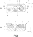
- the cartridge 3 holding the rotary member 5 therein in the above-described manner is mounted on the tool body 2 such that its upper surface is flush with the upper surface of the tool body 2.
- the cartridge 3 is mounted such that the outer peripheral surface of the rotary member 5 held in the cartridge 3 is brought into contact with the rotary member containing portion 13 of the tool body 2.
- the outer peripheral surfaces of the first and second substantially cylindrical portions 17 and 18 of the rotary member 5 abut against the first and second concave curves 14 and 15 of the tool body 2, respectively.
- the outer peripheral surface of the third substantially cylindrical portion (i.e., the cam portion) 19 of the rotary member 5 abuts against the third concave curve 16 of the tool body 2.
- a step E (see (B) of Fig. 8 ) between the flat surface (i.e., a cam receiving surface) of the third concave curve 16 and each of the first and second concave curves 14 and 15 has a length substantially equivalent to a difference F (see (B) of Fig. 3 ) between the radius of each of the first and second substantially cylindrical portions 17 and 18 of the rotary member 5 and the radius of the cam portion 19 at the point A (i.e., the minimum radius of the cam).
- the cutting edge adjustment device 1 is in an initial state in which the movement amount of a cutting edge is zero (i.e., the movement amount of the cutting insert 4 is zero), as shown in (A) and (B) of Fig. 8 .
- the fixing screw 9 is screwed to the screw hole 8, so that the cartridge 3 is fixed to the tool body 2, as shown in (D-1) and (D-2) of Fig. 6 .
- the indication mark 41 as the set mark on the cartridge 3 matches with the set mark 22 on the rotary member 5.
- the cartridge 3 and the rotary member 5 are mounted on the tool body 2, thus completing the assembly of the cutting edge adjustment device 1 in the present embodiment.
- the rotary member 5 is not such configured as the embodiment shown in (A) to (C) of Fig. 3 , for example, even if the rotary member 5 includes a cam portion, a substantially cylindrical portion, and another cam portion arranged in this order, the portions for holding the rotary member 5 in the tool body 2 and the cartridge 3 can be formed into shapes in conformity with that of the rotary member 5, as described above, and therefore, the cartridge 3 and the rotary member 5 can be basically mounted on the tool body 2 in the same manner as described above.
- the set mark 22 and the indication mark 41 match with each other in the initial state.
- the cam portion abuts against the flat surface of the third concave curve 16 of the tool body 2 at the point A at which the cam has the minimum radius, so that the cartridge 3 and the cutting insert 4 are most eccentrically located at the proximal end (i.e., the most retreated position of the cutting edge).
- a wrench or the like is fitted into the fitting hole 20, so that the rotary member 5 is rotated in a direction in which the radius of the third substantially cylindrical portion 19 of the rotary member 5 (i.e., the radius of the cam) is increased.
- FIG. 1 shows that the rotary member 5 is rotated in a direction in which the radius of the third substantially cylindrical portion 19 of the rotary member 5 (i.e., the radius of the cam) is increased.
- the fixing screw 9 which fixes the cartridge 3 to the tool body 2 is not descrewed from the fixed hole 25, the small-diameter hole 27 of the fixed hole 25 formed into the substantially elongated or elliptical shape elongated in the movement direction allows the movement of the cartridge 3.
- the fixing screw 9 may be fastened to the screw hole 8 enough to temporarily fix the cartridge 3 or may be fully fastened.
- a pressing force produced by the rotation of the rotary member 5 is sufficiently greater than the maximum value of a cartridge restraint force produced by fastening the fixing screw 9, the cartridge 3 can be moved even in the fastened state of the fixing screw 9.
- the fixed hole 25 formed at the cartridge 3 is formed into a shape elongated in the movement direction of the cartridge 3 (i.e., the positional adjustment direction of the cutting insert 4), and therefore, a play is previously provided at the fixed hole 25 in the cutting edge adjustment direction.
- the cartridge 3 can be moved by the amount of the play.
- the rotation of the rotary member 5 in this manner can achieve the movement of the cartridge 3, and thus, can implement the adjustment of the cutting edge at a desired position.
- the fixing screw 9 is temporarily fixed, it is fully fastened after the adjustment.
- the cam portion 19 of the rotary member 5 is formed into such a shape that the radius is linearly increased counterclockwise over the substantially entire circumference from the point A to the point B.
- the unit rotational angle amount of the rotary member 5 and the unit increase amount of the radius are set proportionally to each other.
- an operator can very readily adjust the movement amount of the cutting edge, unlike in the typical cam type cutting edge adjustment device as disclosed in Patent Literature 1.
- the position of the cutting edge can be adjusted with high accuracy.
- the orientation of the wrench arm unfitted to the fitting hole 20 can show the rotational amount of the rotary member 5 and the movement amount of the cutting edge.
- the scale including the plurality of marks 21 and the set mark 22 is additionally provided at the end of the rotary member 5, like in the present embodiment, thus more facilitating the adjustment of the movement amount of the cutting edge.
- the position of the cutting edge can be accurately and rapidly adjusted without using a measuring instrument such as a dial indicator together.
- the set mark 22 formed for indicating that the movement amount of the cutting edge is zero is matched with the indication mark 41, thus more facilitating the control of the movement amount of the cutting edge.
- the shapes and forms of the marks 21, the set mark 22, and the indication mark 41 are not limited to those shown in (B) of Fig. 3 and the like, and therefore, they may be appropriately varied.
- the marks may be formed into triangles or rectangles.
- the marks may be formed into shapes of significant characters, symbols, or numbers such as "S" representing the set mark or "0" representing an origin.
- these marks or the scale may not be engraved, unlike described above. For example, they may be printed or stuck with a print piece, or may be formed into a relief pattern.
- an indication mark is formed at the end of the substantially cylindrical portion 17 of the rotary member 5 whereas a plurality of marks may be appropriately formed at the upper surface of the cartridge 3 and/or the tool body 2 contiguous to the end, thus forming a scale.
- the rotary member 5 can be securely held between both ends of each of the first and second concave curves 31 and 32 by the elastic force of the elastically deformable portions 39 of the cartridge 3. Therefore, the cartridge 3 and the rotary member 5 integrally have high rigidity. Even after the rotation of the rotary member 5 adjusts the cutting edge, it is possible to suppress any shift of the rotary member 5. Particularly in cutting, the rotary member 5 receives a large force caused by cutting resistance or a centrifugal force produced by the rotation of a workpiece to be cut or the tool body. In view of this, an improvement in mounting rigidity in this manner is a big advantage.
- the rotary member 5 may be configured in such a manner as to be fixed by fixing unit such as a screw according to the present invention.
- the portions abutting against the rotary member 5 are restricted to the abutment surface 36 oriented in the movement direction of the cartridge 3 in parallel to the X axis (i.e., the positional adjustment direction of the cutting insert 4) and the abutment surfaces 34 and 38 oriented in the Y-axial direction substantially perpendicular to the movement direction of the cartridge 3: in contrast, the other portions act as the flanks 35 and 37 (see (A) of Fig. 7 ). Therefore, even if the first or second substantially cylindrical portion 17 or 18 is somewhat deformed because of manufacturing tolerances, the abutment can be stably kept all the time.
- the rotary member 5 can be stably supported, and at the same time, the rotary member 5 or the cartridge 3 can be effectively prevented from being broken.
- the axis in the depth direction of the hole integrally including the fixed hole 25 of the cartridge 3, into which the fixing screw 9 is inserted, and the screw hole 8 of the tool body 2 is substantially perpendicular to the movement direction of the cutting insert 4 (i.e., the X-axial direction), and further, its back is inclined toward the inside surface defining the recess 6 of the tool body 2, that is, in a direction oriented to the longitudinal side surface 10 (i.e., in a direction in which it is inclined with respect to the upper surface of the cartridge 3).
- the fixed hole 25 of the cartridge 3 is formed into the shape obtained by connecting the large-diameter hole 26 to the small-diameter hole 27 via the step, thus making it possible to completely contain the head 29 of the fixing screw 9 below the surface of the cartridge 3. Therefore, chips produced by cutting cannot be inhibited by the head 29 of the fixing screw 9, thus achieving an excellent chip discharging ability.
- the cutting edge adjustment device 1 in the present embodiment basically has the very simple configuration including the tool body 2, the cartridge 3, the cutting insert 4, the rotary member 5, and the fixing screw 9, and therefore, the number of required component parts can be remarkably reduced in comparison with the typical construction. Consequently, the cutting edge adjustment device 1 capable of readily and rapidly adjusting the cutting edge with high accuracy can be fabricated at a reduced cost.
- the movement direction of the cutting edge may be arbitrarily varied by varying the mounting position or direction of the rotary member 5.
- the present invention provides an adjustment device that is applicable according to all movement directions in a case where the movement of the cutting edge is needed or should be varied.
- the number of rotary members 5 used according to the present invention is not limited to one as described above. Specifically, a plurality of rotary members 5 may be combined, thus achieving a more complicated positional adjustment.
- the adjustment device according to the present invention is applicable to all kinds of cutting tools such as a turning tool, a milling tool, and a drilling tool.
- the shapes and mounting positions of the cartridge 3 and rotary member 5 may be appropriately varied according to the shape of the tool or tool body or the purpose of the adjustment.
- a cutting insert 4' is configured such that a rotary member holding portion 30' similar to the above-described rotary member holding portion 30 is formed at a lateral surface, and concave curves for receiving the rotary member 5 are provided at the rotary member holding portion 30', as shown in Fig. 10 , thus enhancing the fixability of the rotary member 5. It is preferable to form an elastically deformable portion 39' and a chamfer 40' inside of the end of the elastically deformable portion 39'.
- a fixed hole 24' to be used in fixing the cutting insert 4' to the tool body may be formed in the same manner as the above-described fixed hole 25 of the cartridge 3.
- a configuration similar to that at the above-described cartridge 3 may be applied to the cutting insert 4.
- at least another pressing member serving as a displacement transmitting member may be interposed between the cutting insert 4 and the rotary member 5, and thus, the rotary member 5 may press the cutting insert 4 via the pressing member.
- a configuration similar to that at the above-described cartridge 3 may be applied to the pressing member.
- the pressing member does not perform the connection by holding the cutting insert 4, as described above, it is to be understood that the pressing member can serve as the cartridge to be connected to the cutting insert 4 as the displacement transmitting mechanism in a state mounted on the tool body 2.
- the rotary member containing portion 13 formed at the tool body 2 may be formed at the cartridge 3.
- the configuration and function of holding the rotary member 5 by the cartridge 3 and the tool body 2 may be changed from those in the above-described embodiment. In this case, the above-described various advantageous results can be produced in the same manner.
- an urging member such as a spring consistently presses the cartridge 3 against the rotary member 5 by a constant force.
- the cartridge 3 is brought into close contact with the rotary member 5 all the time, thus preventing the cartridge 3 from being shifted toward the cutting insert 4 by the influence of gravity or the like, so as to more readily adjust the position of the cutting edge.
Landscapes
- Engineering & Computer Science (AREA)
- Mechanical Engineering (AREA)
- Milling Processes (AREA)
- Cutting Tools, Boring Holders, And Turrets (AREA)
- Details Of Cutting Devices (AREA)
Claims (21)
- Schneidkanteneinstellvorrichtung (1) für ein Schneidwerkzeug zum Einstellen der Position einer Schneidkante eines Schneideinsatzes (4) durch Hervorrufen einer Bewegung des Schneideinsatzes (4), wobei die Schneidkanteneinstellvorrichtung (1) umfasst:zumindest ein Drehelement (5) zur Erzeugung der Bewegung;eine Kassette (3), an der der Schneideinsatz (4) befestigt ist; undeinen Werkzeugkörper (2), auf dem die Kassette (2) gelagert ist,wobei das Drehelement (5) zu einer Form ausgebildet ist, die zumindest einen im Wesentlichen zylindrischen Abschnitt (17, 18) mit einer Außenumfangsfläche, deren Radius konstant ist, und zumindest einen Nockenabschnitt (19) mit einer Nockenfläche aufweist, deren Radius allmählich so zunimmt, dass er dem Ausmaß der Bewegung entspricht, wobei das Drehelement (5) einen ersten und einen zweiten im Wesentlichen zylindrischen Abschnitt (17, 18aufweist, die jeweils einen konstanten Radius aufweisen, wobei der erste im Wesentlichen zylindrische Abschnitt (17), der Nockenabschnitt (19) und der zweite im Wesentlichen zylindrische Abschnitt (18) in dieser Reihenfolge entlang der Drehmittelachse (O) miteinander verbunden sind,wobei das Drehelement (5) über die Kassette (3) durch die Wirkung der Nockenfläche entsprechend der Drehung des Drehelements (5) um die Drehmittelachse (O) gegen den Schneideinsatz (4) gedrückt wird, um die Position der Schneidkante einzustellen,wobei die Kassette (3) einen Abschnitt (30) aufweist, der so ausgebildet ist, dass er entweder an dem im Wesentlichen zylindrischen Abschnitt (17, 18) oder an dem Nockenabschnitt (19) anliegt,dadurch gekennzeichnet, dassder Werkzeugkörper (2) einen Abschnitt (13) aufweist, der so ausgebildet ist, dass er an dem anderen aus im Wesentlichen zylindrischem Abschnitt (17, 18) und Nockenabschnitt (19) anliegt,wobei eine Position, in der die Nockenfläche des Nockenabschnitts (19) an dem Abschnitt zum Anliegen an dem Nocken (19) anliegt, entsprechend der Drehung des Drehelements (5) verändert wird, so dass das Drehelement (5) auf die Kassette (3) drückt, um die Position der Schneidkante einzustellen.
- Schneidkanteneinstellvorrichtung (1) nach Anspruch 1, wobei die Kassette (3) konkave Krümmungen (31, 32) aufweist, die an dem im Wesentlichen zylindrischen Abschnitt (17, 18) des Drehelements (5) anliegen.
- Schneidkanteneinstellvorrichtung (1) nach Anspruch 2, wobei die Kassette (3) zumindest eine konkave Krümmung (31, 32) aufweist, die an dem im Wesentlichen zylindrischen Abschnitt (17, 18) des Drehelements (5) anliegt, sowie zumindest eine konkave Krümmung (33), die an den Nockenabschnitt (19) angrenzt, aber nicht an diesem anliegt.
- Schneidkanteneinstellvorrichtung (1) nach Anspruch 3, wobei jede der konkaven Krümmungen (31, 32), die an dem im Wesentlichen zylindrischen Abschnitt (17, 18) des Drehelements (5) anliegen, zu einer im Wesentlichen C-förmigen Gestalt ausgebildet ist, deren Enden auf der Seite des Drehelements (5) liegen, gesehen in einer Richtung parallel zur Drehmittelachse,wobei ein Abstand (L) zwischen den Enden der im Wesentlichen C-förmigen Gestalt kleiner ist als der Durchmesser des im Wesentlichen zylindrischen Abschnitts (17, 18) des Drehelements (5), undwobei zumindest ein Ende der im Wesentlichen C-förmigen Gestalt als ein elastisch verformbarer Abschnitt (39) ausgebildet ist, der elastisch verformt werden kann.
- Schneidkanteneinstellvorrichtung (1) nach Anspruch 3 oder Anspruch 4, wobei die Kassette (3) eine erste konkave Krümmung (31) aufweist, die so ausgebildet ist, dass sie an der Außenumfangsfläche des ersten im Wesentlichen zylindrischen Abschnitts (17) anliegt, sowie eine zweite konkave Krümmung (32), die so ausgebildet ist, dass sie an der Außenumfangsfläche des zweiten im Wesentlichen zylindrischen Abschnitts (18) anliegt, und eine dritte konkave Krümmung (33), die so ausgebildet ist, dass sie tiefer als die erste und die zweite konkave Krümmung (31, 32) ausgeführt ist, so dass sie an die Nockenfläche des Nockenabschnitts (19) angrenzt, aber nicht an dieser anliegt.
- Schneidkanteneinstellvorrichtung (1) nach Anspruch 5, wobei die erste und die zweite konkave Krümmung (33) der Kassette (3) jeweils nur teilweise an den Außenumfangsflächen des ersten und des zweiten im Wesentlichen zylindrischen Abschnitts (17, 18) des Drehelements (5) anliegen.
- Schneidkanteneinstellvorrichtung (1) nach Anspruch 6, wobei Abschnitte (34, 36, 38) an jeder der ersten und zweiten konkaven Krümmung der Kassette (3), die an den Außenumfangsflächen des ersten und zweiten im Wesentlichen zylindrischen Abschnitts (17, 18) des Drehelements (5) anliegen, eine Anlagefläche (36) bilden, die so ausgebildet ist, dass sie in der Bewegungsrichtung des Schneideinsatzes (4) ausgerichtet ist, und Anlageflächen (34, 38) bilden, die so ausgebildet sind, dass sie in einer Richtung im Wesentlichen senkrecht zur Bewegungsrichtung des Schneideinsatzes (4) ausgerichtet sind.
- Schneidkanteneinstellvorrichtung (1) nach einem der Ansprüche 1 bis 7, wobei an der Kassette (3) eine Befestigungsbohrung (25) in Form einer Durchgangsbohrung ausgebildet ist, in die eine Befestigungsschraube (9) eingesetzt ist, um die Kassette (3) am Werkzeugkörper (2) zu befestigen,
wobei die Befestigungsbohrung (25) eine im Wesentlichen längliche oder elliptische Form aufweist, die in der Bewegungsrichtung des Schneideinsatzes (4) relativ langgestreckt ist. - Schneidkanteneinstellvorrichtung (1) nach Anspruch 8, wobei die Befestigungsbohrung (25) eine Bohrung (26) mit größerem Durchmesser und eine Bohrung (27) mit kleinerem Durchmesser umfasst, wobei diese Bohrungen über eine Stufe in Tiefenrichtung miteinander verbunden sind,
wobei der Durchmesser der Bohrung (26) mit größerem Durchmesser größer ist als der eines Schraubenkopfs (29) der Befestigungsschraube (9), der Durchmesser der Bohrung (27) mit kleinerem Durchmesser kleiner ist als der des Schraubenkopfs (29) der Befestigungsschraube (9) und größer als der eines Schafts (28) der Befestigungsschraube (9), und wobei ferner die Tiefe der Bohrung (26) mit größerem Durchmesser größer ist als die Höhe des Schraubenkopfs (29) der Befestigungsschraube (9). - Schneidkanteneinstellvorrichtung (1) nach Anspruch 8 oder Anspruch 9, wobei die Achse der Befestigungsbohrung (25) der Kassette (3) in der Tiefenrichtung im Wesentlichen senkrecht zur Bewegungsrichtung des Schneideinsatzes (4) verläuft und in Bezug auf die obere Fläche der Kassette (3), zu der die Befestigungsbohrung (25) geöffnet ist, geneigt verläuft.
- Schneidkanteneinstellvorrichtung (1) für ein Schneidwerkzeug zum Einstellen der Position einer Schneidkante eines Schneideinsatzes (4) durch Hervorrufen einer Bewegung des Schneideinsatzes (4), wobei die Schneidkanteneinstellvorrichtung (1) umfasst:zumindest ein Drehelement (5) zur Erzeugung der Bewegung;einen Schneideinsatz (4); undeinen Werkzeugkörper (2), an dem der Schneideinsatz (4) gelagert ist,wobei das Drehelement (5) zu einer Form ausgebildet ist, die in der Reihenfolge entlang einer Drehmittelachse (O) zumindest einen im Wesentlichen zylindrischen Abschnitt (17, 18) mit einer Außenumfangsfläche, deren Radius konstant ist, und zumindest einen Nockenabschnitt (19) mit einer Nockenfläche, deren Radius allmählich so zunimmt, dass er dem Ausmaß der Bewegung entspricht, aufweist,dadurch gekennzeichnet, dassdas Drehelement (5) durch die Wirkung der Nockenfläche entsprechend der Drehung des Drehelements (5) um die Drehmittelachse (O) gegen den Schneideinsatz (4) gedrückt wird, um die Position der Schneidkante einzustellen,wobei der Schneideinsatz (4) einen Abschnitt (30') aufweist, der so ausgebildet ist, dass er entweder an dem im Wesentlichen zylindrischen Abschnitt (17, 18) oder an dem Nockenabschnitt (19) anliegt,wobei der Werkzeugkörper (2) einen Abschnitt (13) aufweist, der so ausgebildet ist, dass er an dem anderen aus dem im Wesentlichen zylindrischem Abschnitt (17, 18) und dem Nockenabschnitt (19) anliegt, undwobei eine Position, an der die Nockenfläche des Nockenabschnitts (19) an dem Abschnitt zum Anliegen an dem Nocken (19) anliegt, entsprechend der Drehung des Drehelements (5) verändert wird, so dass das Drehelement (5) den Schneideinsatz (4) andrückt, um die Position der Schneidkante einzustellen.
- Schneidkanteneinstellvorrichtung (1) für ein Schneidwerkzeug zum Einstellen der Position einer Schneidkante eines Schneideinsatzes (4) durch Hervorrufen einer Bewegung des Schneideinsatzes (4), wobei die Schneidkanteneinstellvorrichtung (1) aufweist:zumindest ein Drehelement (5) zur Erzeugung der Bewegung;den Schneideinsatz (4) und zumindest ein Andrückelement; undeinen Werkzeugkörper (2), an dem das Andrückelement gelagert ist,wobei das Drehelement (5) zu einer Form ausgebildet ist, die in der Reihenfolge entlang einer Drehmittelachse (O) zumindest einen im Wesentlichen zylindrischen Abschnitt (17, 18) mit einer Außenumfangsfläche, deren Radius konstant ist, und zumindest einen Nockenabschnitt (19) mit einer Nockenfläche, deren Radius allmählich so zunimmt, dass er dem Ausmaß der Bewegung entspricht, aufweist,wobei das Drehelement (5) über das zumindest eine Andrückelement durch die Wirkung der Nockenfläche entsprechend der Drehung des Drehelements (5) um die Drehmittelachse (O) gegen den Schneideinsatz (4) gedrückt wird, um die Position der Schneidkante einzustellen,wobei das Andrückelement einen Abschnitt aufweist, der dazu ausgebildet ist, entweder an dem im Wesentlichen zylindrischen Abschnitt (17, 18) oder an dem Nockenabschnitt (19) anzuliegen,dadurch gekennzeichnet, dassder Werkzeugkörper (2) einen Abschnitt (13) aufweist, der so ausgebildet ist, dass er an dem anderen aus dem im Wesentlichen zylindrischem Abschnitt (17, 18) und dem Nockenabschnitt (19) anliegt, undwobei eine Position, an der die Nockenfläche des Nockenabschnitts (19) an dem Abschnitt zum Anliegen an dem Nocken (19) anliegt, entsprechend der Drehung des Drehelements (5) verändert wird, so dass das Drehelement (5) das Andrückelement andrückt, um die Position der Schneidkante einzustellen.
- Schneidkanteneinstellvorrichtung (1) nach Anspruch 11 oder Anspruch 12, wobei der Abschnitt, der an dem Drehelement (5) anliegt, zumindest eine konkave Krümmung aufweist, die an dem im Wesentlichen zylindrischen Abschnitt (17, 18) des Drehelements (5) anliegt, sowie zumindest eine konkave Krümmung, die an den Nockenabschnitt (19) angrenzt, aber nicht an diesem anliegt.
- Schneidkanteneinstellvorrichtung (1) nach Anspruch 13, wobei die konkave Krümmung, die an dem im Wesentlichen zylindrischen Abschnitt (17, 18) des Drehelements (5) anliegt, zu einer im Wesentlichen C-förmigen Gestalt ausgebildet ist, deren Enden auf der Seite des Drehelements (5) liegen, gesehen in einer Richtung parallel zur Drehmittelachse,wobei ein Abstand zwischen den Enden der im Wesentlichen C-förmigen Gestalt kleiner ist als der Durchmesser des im Wesentlichen zylindrischen Abschnitts (17, 18) des Drehelements (5), undwobei zumindest ein Ende der im Wesentlichen C-förmigen Gestalt ein elastisch verformbarer Abschnitt ist, der elastisch verformt werden kann.
- Schneidkanteneinstellvorrichtung (1) nach Anspruch 14, wobei die konkave Krümmung, die an dem im Wesentlichen zylindrischen Abschnitt (17, 18) des Drehelements (5) anliegt, nur teilweise an der Außenumfangsfläche des im Wesentlichen zylindrischen Abschnitts (17, 18) des Drehelements (5) anliegt.
- Schneidkanteneinstellvorrichtung (1) nach Anspruch 15, wobei es sich bei den Abschnitten, die an den Außenumfangsflächen der im Wesentlichen zylindrischen Abschnitte (17, 18) des Drehelements (5) anliegen, um eine Anlagefläche handelt, die so ausgebildet ist, dass sie in der Bewegungsrichtung des Schneideinsatzes (4) ausgerichtet ist, sowie um eine Anlagefläche, die so ausgebildet ist, dass sie in einer Richtung im Wesentlichen senkrecht zur Bewegungsrichtung des Schneideinsatzes (4) ausgerichtet ist.
- Schneidkanteneinstellvorrichtung (1) nach einem der Ansprüche 1 bis 16, wobei der Radius der Nockenfläche über den im Wesentlichen gesamten Umfang linear zunimmt.
- Schneidkanteneinstellvorrichtung (1) nach einem der Ansprüche 1 bis 17, wobei ein Einheitsdrehwinkel des Drehelements (5) proportional zu einem Einheitsbewegungsausmaß des Schneideinsatzes (4) ist.
- Schneidkanteneinstellvorrichtung (1) nach einem der Ansprüche 1 bis 18, ferner aufweisend eine Skala zur Anzeige des Drehbewegungsausmaßes des Drehelementes (5) und eine Anzeigemarkierung zum Anzeigen auf der Skala,
wobei das Drehelement (5) ein sichtbares Ende aufweist, an dem die Skala oder die Anzeigemarkierung ausgebildet ist. - Verwendung der Schneidkanteneinstellvorrichtung (1) nach einem der Ansprüche 1 bis 10 zum Einstellen der Position einer Schneidkante eines Schneideinsatzes (4) durch Andrücken einer Kassette (3), wobei der Schneideinsatz (4) mit der Kassette (3) verbunden ist.
- Verwendung der Schneidkanteneinstellvorrichtung (1) nach Anspruch 11 zum Einstellen der Position einer Schneidkante eines Schneideinsatzes (4'), wobei der Schneideinsatz (4') eine konkave Krümmung aufweist, die so an dem Drehelement (5) anliegt, dass sie direkt gegen das Drehelement (5) gedrückt wird.
Applications Claiming Priority (2)
| Application Number | Priority Date | Filing Date | Title |
|---|---|---|---|
| JP2012173585 | 2012-08-06 | ||
| PCT/JP2013/071187 WO2014024852A1 (ja) | 2012-08-06 | 2013-08-05 | 刃先調整装置、該装置に適用される回転部材、並びに、前記装置に適した構造を有する工具ボデー、カートリッジ及び切削インサート |
Publications (3)
| Publication Number | Publication Date |
|---|---|
| EP2881202A1 EP2881202A1 (de) | 2015-06-10 |
| EP2881202A4 EP2881202A4 (de) | 2016-03-09 |
| EP2881202B1 true EP2881202B1 (de) | 2024-10-30 |
Family
ID=50068076
Family Applications (1)
| Application Number | Title | Priority Date | Filing Date |
|---|---|---|---|
| EP13827937.7A Active EP2881202B1 (de) | 2012-08-06 | 2013-08-05 | Schneidekanteneinstellungsvorrichtung |
Country Status (5)
| Country | Link |
|---|---|
| US (1) | US9751137B2 (de) |
| EP (1) | EP2881202B1 (de) |
| JP (2) | JP6305339B2 (de) |
| CN (2) | CN107008928B (de) |
| WO (1) | WO2014024852A1 (de) |
Families Citing this family (17)
| Publication number | Priority date | Publication date | Assignee | Title |
|---|---|---|---|---|
| EP2881202B1 (de) * | 2012-08-06 | 2024-10-30 | Tungaloy Corporation | Schneidekanteneinstellungsvorrichtung |
| GB2525620A (en) * | 2014-04-29 | 2015-11-04 | Rigibore Ltd | Cutting tool assembly |
| US10384279B2 (en) | 2015-07-10 | 2019-08-20 | Tungaloy Corporation | Tool, adjustment mechanism, tool body and cutting tool |
| US10220453B2 (en) * | 2015-10-30 | 2019-03-05 | Ford Motor Company | Milling tool with insert compensation |
| US10131005B2 (en) * | 2017-01-10 | 2018-11-20 | Kennametal Inc. | Adjustable cartridge assembly for cutting tool |
| JP6268626B1 (ja) * | 2017-05-11 | 2018-01-31 | 株式会社タンガロイ | 回転切削工具 |
| US11458553B2 (en) * | 2017-10-10 | 2022-10-04 | Tungaloy Corporation | Cartridge and milling tool |
| AT16360U1 (de) * | 2017-11-15 | 2019-07-15 | Ceratizit Austria Gmbh | Für Auslieferung konfektioniertes Zerspanungswerkzeug |
| CN111405956B (zh) * | 2017-11-30 | 2023-08-22 | 伊斯卡有限公司 | 具有能更换的适配器的模块化的车削工具 |
| CN107962213A (zh) * | 2017-12-01 | 2018-04-27 | 无锡锡压压缩机有限公司 | 一种螺杆压缩机壳体类零件铣削加工装置和铣削加工方法 |
| JP6933165B2 (ja) * | 2018-03-12 | 2021-09-08 | 三菱マテリアル株式会社 | 切削工具用カートリッジの調整機構および切削工具 |
| JP2020023001A (ja) * | 2018-08-06 | 2020-02-13 | 株式会社ジェイテクト | 旋削用工具、歯車加工装置及び歯車加工方法 |
| CN111360394B (zh) * | 2018-12-25 | 2021-09-17 | 杭州海康微影传感科技有限公司 | 一种激光调节机构 |
| CN115210021A (zh) * | 2020-03-04 | 2022-10-18 | 本田技研工业株式会社 | 加工工具 |
| EP3888826A1 (de) * | 2020-03-31 | 2021-10-06 | CERATIZIT Austria Gesellschaft m.b.H. | Zerspanungswerkzeug und verfahren zum indexieren eines schneideinsatzes |
| JP6860866B1 (ja) * | 2020-08-12 | 2021-04-21 | 株式会社タンガロイ | 切削インサート |
| TWI806763B (zh) * | 2022-09-08 | 2023-06-21 | 鼎鎮實業有限公司 | 組合式刀具 |
Citations (2)
| Publication number | Priority date | Publication date | Assignee | Title |
|---|---|---|---|---|
| EP0033086B1 (de) * | 1980-01-14 | 1983-10-12 | Firma Gottlieb Gühring | Bohrwerkzeug mit einem Wendebohrmesser |
| JPH01295709A (ja) * | 1988-03-11 | 1989-11-29 | Sandvik Ab | フライス |
Family Cites Families (43)
| Publication number | Priority date | Publication date | Assignee | Title |
|---|---|---|---|---|
| JPS4621182Y1 (de) * | 1968-02-05 | 1971-07-22 | ||
| FR2140723A5 (de) * | 1971-03-25 | 1973-01-19 | Garih Claude | |
| US3798724A (en) * | 1972-07-28 | 1974-03-26 | Gorham Tool Co | Locking arrangement for cutting blade inserts |
| JPS4978991A (de) * | 1972-11-16 | 1974-07-30 | ||
| US3887975A (en) | 1974-05-13 | 1975-06-10 | Kennametal Inc | Slotting cutter and cutting insert therefor |
| US4022539A (en) * | 1975-05-23 | 1977-05-10 | J. P. Tool, Inc. | Boring bar structure |
| DE2754499A1 (de) * | 1977-12-07 | 1979-06-13 | Hans Heinlein | Mikroeinstellvorrichtung fuer wendeplatten |
| JPS5538702U (de) * | 1978-08-15 | 1980-03-12 | ||
| JPS6342967Y2 (de) * | 1980-08-12 | 1988-11-10 | ||
| DE3042050A1 (de) * | 1980-11-07 | 1982-07-08 | Müller & Christner GmbH & Co KG, 7430 Metzingen | Vorrichtung zum einstellen eines schneidkoerpers gegenueber einem traeger |
| JPS5866611A (ja) * | 1981-10-12 | 1983-04-20 | Toshiba Mach Co Ltd | 正面フライスカツタ |
| SE501915C2 (sv) * | 1993-03-18 | 1995-06-19 | Sandvik Ab | Finfräs med urtag för axiellt inställbara kassetter |
| SE508387C2 (sv) * | 1993-05-26 | 1998-10-05 | Sandvik Ab | Rundskär |
| DE4407270C1 (de) * | 1994-03-04 | 1995-03-09 | Fleischmann Apparatebau | Schneidplatten-Einstellvorrichtung |
| DE19725219C2 (de) * | 1997-06-15 | 1999-05-20 | Walter Ag | Fräswerkzeug mit axialer Einstellung des Plattensitzes |
| CN2399135Y (zh) * | 1998-06-09 | 2000-10-04 | 张新添 | 切削刀具微调结构 |
| US6056484A (en) | 1998-08-07 | 2000-05-02 | Kennametal Inc. | Device and method for adjusting the position of cutting inserts mounted in a cutting tool |
| US6406225B1 (en) * | 2000-05-01 | 2002-06-18 | Stojan Stojanovski | Boring head assembly |
| US7114890B2 (en) * | 2001-02-13 | 2006-10-03 | Valenite Inc. | Cutting tool adjustment device |
| US6325574B1 (en) * | 2001-02-14 | 2001-12-04 | Peter J. Treige | Machining slot cutter with removable cartridges |
| SE523224C2 (sv) * | 2001-11-21 | 2004-04-06 | Sandvik Ab | Roterbart skärverktyg |
| US6739807B2 (en) | 2001-11-26 | 2004-05-25 | Valenite Llc | Rotatable cutting tool |
| SE523286C2 (sv) * | 2001-11-27 | 2004-04-06 | Sandvik Ab | Verktyg för spånavskiljande bearbetning med ställmekanism för skäret |
| US6702526B2 (en) | 2002-04-29 | 2004-03-09 | Kennametal Inc. | Cutting tool |
| JP4227955B2 (ja) * | 2002-04-29 | 2009-02-18 | ケンナメタル インコーポレイテッド | 切削工具 |
| IL154472A (en) | 2003-02-16 | 2007-10-31 | Amir Satran | Cutting tool and cartridge therefor |
| US6942432B2 (en) * | 2003-03-28 | 2005-09-13 | Sandvik Intellectual Property Ab | Milling cutter and insert-carrying cartridge for use therein |
| SE529311C2 (sv) | 2005-12-05 | 2007-07-03 | Seco Tools Ab | Ett verktyg för spånavskiljande bearbetning där gängförbandet är anordnat att tillåta vickning av låsskruven |
| US7390150B2 (en) | 2006-05-03 | 2008-06-24 | Valenite Llc | Cutting tool with adjustable indexable cutting insert |
| IL182078A (en) | 2007-03-20 | 2011-09-27 | Iscar Ltd | System for attaching a cutting member to a cutter |
| IL190734A (en) | 2008-04-08 | 2013-08-29 | Iscar Ltd | Adjustment mechanism |
| WO2009151168A1 (en) | 2008-06-13 | 2009-12-17 | Taegutec Ltd. | Cutting tool and cartridge for the same |
| IL195601A (en) | 2008-11-30 | 2013-11-28 | Iscar Ltd | Daphne mechanism |
| IL196440A (en) * | 2009-01-11 | 2012-03-29 | Iscar Ltd | Adjustment mechanism |
| IL197205A0 (en) * | 2009-02-24 | 2009-12-24 | Iscar Ltd | Cutting tool having adjustment mechanism |
| IL204222A (en) * | 2010-03-01 | 2014-04-30 | Iscar Ltd | Cutting tool system with a pitch mechanism |
| US8506209B2 (en) * | 2011-07-26 | 2013-08-13 | Iscar, Ltd. | Adjustable cutting tool |
| EP2773478B1 (de) * | 2011-11-04 | 2016-01-06 | Walter AG | Kartusche mit grob- und feineinstellungsmitteln |
| EP2881202B1 (de) | 2012-08-06 | 2024-10-30 | Tungaloy Corporation | Schneidekanteneinstellungsvorrichtung |
| US9216464B2 (en) | 2012-11-15 | 2015-12-22 | Iscar, Ltd. | Milling tool and milling tool body having pressure holes for securing cutting inserts |
| US8851807B2 (en) | 2012-12-26 | 2014-10-07 | Iscar, Ltd. | Cutting tool having axial position adjustment arrangement |
| US9216458B2 (en) * | 2014-02-19 | 2015-12-22 | Iscar, Ltd. | Cutting tool having adjustable insert cutting angle |
| US9862040B2 (en) * | 2014-09-30 | 2018-01-09 | Sandvik Intellectual Property Ab | Mechanism for enhanced, bi-directional fine adjustment of cutting insert cartridges in machine tools |
-
2013
- 2013-08-05 EP EP13827937.7A patent/EP2881202B1/de active Active
- 2013-08-05 WO PCT/JP2013/071187 patent/WO2014024852A1/ja not_active Ceased
- 2013-08-05 JP JP2014529495A patent/JP6305339B2/ja active Active
- 2013-08-05 CN CN201710178384.XA patent/CN107008928B/zh active Active
- 2013-08-05 CN CN201380041905.7A patent/CN104520038B/zh active Active
- 2013-08-06 US US14/419,426 patent/US9751137B2/en active Active
-
2016
- 2016-10-17 JP JP2016203562A patent/JP6132176B2/ja active Active
Patent Citations (2)
| Publication number | Priority date | Publication date | Assignee | Title |
|---|---|---|---|---|
| EP0033086B1 (de) * | 1980-01-14 | 1983-10-12 | Firma Gottlieb Gühring | Bohrwerkzeug mit einem Wendebohrmesser |
| JPH01295709A (ja) * | 1988-03-11 | 1989-11-29 | Sandvik Ab | フライス |
Also Published As
| Publication number | Publication date |
|---|---|
| CN107008928B (zh) | 2019-11-15 |
| JP6305339B2 (ja) | 2018-04-04 |
| CN104520038A (zh) | 2015-04-15 |
| CN107008928A (zh) | 2017-08-04 |
| JP6132176B2 (ja) | 2017-05-24 |
| JPWO2014024852A1 (ja) | 2016-07-25 |
| WO2014024852A1 (ja) | 2014-02-13 |
| EP2881202A4 (de) | 2016-03-09 |
| JP2017013227A (ja) | 2017-01-19 |
| US9751137B2 (en) | 2017-09-05 |
| CN104520038B (zh) | 2017-06-23 |
| US20150217384A1 (en) | 2015-08-06 |
| EP2881202A1 (de) | 2015-06-10 |
Similar Documents
| Publication | Publication Date | Title |
|---|---|---|
| EP2881202B1 (de) | Schneidekanteneinstellungsvorrichtung | |
| US7780380B2 (en) | Insert-indexable tool | |
| CN1532013B (zh) | 刀片和铣刀 | |
| EP2764939B2 (de) | Schneidewerkzeug mit austauschbarer klingenkante | |
| EP2878405B1 (de) | Wendeschneidwerkzeug | |
| EP2883640B1 (de) | Schneidwerkzeug mit Anschlägen und Werkzeughalter und Schneideinsatz dafür | |
| US11484949B2 (en) | Cutting insert and cutting tool | |
| KR20040002650A (ko) | 인서트, 홀더 및 절삭공구 | |
| JPWO2010100953A1 (ja) | 切削インサートおよびインサート着脱式切削工具 | |
| EP1986806A1 (de) | Einsatz mit einem loch zur montage und werkzeughalter mit einem schneideeinsatz | |
| US9227246B2 (en) | Cutting tool for grooving and parting operations | |
| EP2332680A1 (de) | Spitzen- und seitenschneider | |
| US8726771B2 (en) | Insert, holder, and cutting tool using said insert and holder | |
| CN110087807B (zh) | 切削刀片及可转位刀片式旋转切削工具 | |
| EP2865473B1 (de) | Schneideinsatz, werkzeugkörper mit darauf montierbarem schneideinsatz und kugelfräser eines typs mit austauschbarer schneide damit | |
| US20070274791A1 (en) | Cutting Tool and a Tool Part with Connecting Surfaces with Grooves and a Method for Manufacturing of the Tool Part | |
| JP2022138246A (ja) | 刃先交換式切削工具の工具本体 | |
| CN100509225C (zh) | 不重磨刀片的夹紧机构 | |
| JP2004160620A (ja) | スローアウェイチップ及びスローアウェイ式切削工具 | |
| JPH10315031A (ja) | ボールエンドミル及びそのスローアウェイチップ | |
| JP2006123037A (ja) | 工具ヘッド | |
| JP2009034819A (ja) | 切削工具 | |
| KR20230162642A (ko) | 절삭 부재, 홀딩 디바이스 및 절삭 부재와 홀딩 디바이스 사이의 회전 정렬을 나타내기 위한 배열을 갖는 절삭 공구 | |
| US20120121346A1 (en) | Regulating element | |
| JP2008238315A (ja) | 切削工具 |
Legal Events
| Date | Code | Title | Description |
|---|---|---|---|
| PUAI | Public reference made under article 153(3) epc to a published international application that has entered the european phase |
Free format text: ORIGINAL CODE: 0009012 |
|
| 17P | Request for examination filed |
Effective date: 20150221 |
|
| AK | Designated contracting states |
Kind code of ref document: A1 Designated state(s): AL AT BE BG CH CY CZ DE DK EE ES FI FR GB GR HR HU IE IS IT LI LT LU LV MC MK MT NL NO PL PT RO RS SE SI SK SM TR |
|
| AX | Request for extension of the european patent |
Extension state: BA ME |
|
| DAX | Request for extension of the european patent (deleted) | ||
| RA4 | Supplementary search report drawn up and despatched (corrected) |
Effective date: 20160204 |
|
| RIC1 | Information provided on ipc code assigned before grant |
Ipc: B23B 29/00 20060101ALI20160129BHEP Ipc: B23C 5/24 20060101AFI20160129BHEP Ipc: B23B 29/034 20060101ALI20160129BHEP |
|
| STAA | Information on the status of an ep patent application or granted ep patent |
Free format text: STATUS: EXAMINATION IS IN PROGRESS |
|
| 17Q | First examination report despatched |
Effective date: 20200810 |
|
| RIN1 | Information on inventor provided before grant (corrected) |
Inventor name: SAJI, RYUICHI |
|
| RIN1 | Information on inventor provided before grant (corrected) |
Inventor name: SAJI, RYUICHI |
|
| RIC1 | Information provided on ipc code assigned before grant |
Ipc: B23C 5/22 20060101ALI20240227BHEP Ipc: B23B 29/034 20060101ALI20240227BHEP Ipc: B23B 29/00 20060101ALI20240227BHEP Ipc: B23C 5/24 20060101AFI20240227BHEP |
|
| GRAP | Despatch of communication of intention to grant a patent |
Free format text: ORIGINAL CODE: EPIDOSNIGR1 |
|
| STAA | Information on the status of an ep patent application or granted ep patent |
Free format text: STATUS: GRANT OF PATENT IS INTENDED |
|
| INTG | Intention to grant announced |
Effective date: 20240527 |
|
| GRAS | Grant fee paid |
Free format text: ORIGINAL CODE: EPIDOSNIGR3 |
|
| GRAA | (expected) grant |
Free format text: ORIGINAL CODE: 0009210 |
|
| STAA | Information on the status of an ep patent application or granted ep patent |
Free format text: STATUS: THE PATENT HAS BEEN GRANTED |
|
| AK | Designated contracting states |
Kind code of ref document: B1 Designated state(s): AL AT BE BG CH CY CZ DE DK EE ES FI FR GB GR HR HU IE IS IT LI LT LU LV MC MK MT NL NO PL PT RO RS SE SI SK SM TR |
|
| REG | Reference to a national code |
Ref country code: GB Ref legal event code: FG4D |
|
| REG | Reference to a national code |
Ref country code: CH Ref legal event code: EP |
|
| REG | Reference to a national code |
Ref country code: DE Ref legal event code: R096 Ref document number: 602013086239 Country of ref document: DE |
|
| REG | Reference to a national code |
Ref country code: IE Ref legal event code: FG4D |
|
| REG | Reference to a national code |
Ref country code: LT Ref legal event code: MG9D |
|
| REG | Reference to a national code |
Ref country code: NL Ref legal event code: MP Effective date: 20241030 |
|
| PG25 | Lapsed in a contracting state [announced via postgrant information from national office to epo] |
Ref country code: HR Free format text: LAPSE BECAUSE OF FAILURE TO SUBMIT A TRANSLATION OF THE DESCRIPTION OR TO PAY THE FEE WITHIN THE PRESCRIBED TIME-LIMIT Effective date: 20241030 Ref country code: IS Free format text: LAPSE BECAUSE OF FAILURE TO SUBMIT A TRANSLATION OF THE DESCRIPTION OR TO PAY THE FEE WITHIN THE PRESCRIBED TIME-LIMIT Effective date: 20250228 Ref country code: PT Free format text: LAPSE BECAUSE OF FAILURE TO SUBMIT A TRANSLATION OF THE DESCRIPTION OR TO PAY THE FEE WITHIN THE PRESCRIBED TIME-LIMIT Effective date: 20250228 |
|
| PG25 | Lapsed in a contracting state [announced via postgrant information from national office to epo] |
Ref country code: NL Free format text: LAPSE BECAUSE OF FAILURE TO SUBMIT A TRANSLATION OF THE DESCRIPTION OR TO PAY THE FEE WITHIN THE PRESCRIBED TIME-LIMIT Effective date: 20241030 Ref country code: FI Free format text: LAPSE BECAUSE OF FAILURE TO SUBMIT A TRANSLATION OF THE DESCRIPTION OR TO PAY THE FEE WITHIN THE PRESCRIBED TIME-LIMIT Effective date: 20241030 |
|
| REG | Reference to a national code |
Ref country code: AT Ref legal event code: MK05 Ref document number: 1736432 Country of ref document: AT Kind code of ref document: T Effective date: 20241030 |
|
| PG25 | Lapsed in a contracting state [announced via postgrant information from national office to epo] |
Ref country code: BG Free format text: LAPSE BECAUSE OF FAILURE TO SUBMIT A TRANSLATION OF THE DESCRIPTION OR TO PAY THE FEE WITHIN THE PRESCRIBED TIME-LIMIT Effective date: 20241030 |
|
| PG25 | Lapsed in a contracting state [announced via postgrant information from national office to epo] |
Ref country code: ES Free format text: LAPSE BECAUSE OF FAILURE TO SUBMIT A TRANSLATION OF THE DESCRIPTION OR TO PAY THE FEE WITHIN THE PRESCRIBED TIME-LIMIT Effective date: 20241030 |
|
| PG25 | Lapsed in a contracting state [announced via postgrant information from national office to epo] |
Ref country code: NO Free format text: LAPSE BECAUSE OF FAILURE TO SUBMIT A TRANSLATION OF THE DESCRIPTION OR TO PAY THE FEE WITHIN THE PRESCRIBED TIME-LIMIT Effective date: 20250130 |
|
| PG25 | Lapsed in a contracting state [announced via postgrant information from national office to epo] |
Ref country code: LV Free format text: LAPSE BECAUSE OF FAILURE TO SUBMIT A TRANSLATION OF THE DESCRIPTION OR TO PAY THE FEE WITHIN THE PRESCRIBED TIME-LIMIT Effective date: 20241030 Ref country code: AT Free format text: LAPSE BECAUSE OF FAILURE TO SUBMIT A TRANSLATION OF THE DESCRIPTION OR TO PAY THE FEE WITHIN THE PRESCRIBED TIME-LIMIT Effective date: 20241030 Ref country code: GR Free format text: LAPSE BECAUSE OF FAILURE TO SUBMIT A TRANSLATION OF THE DESCRIPTION OR TO PAY THE FEE WITHIN THE PRESCRIBED TIME-LIMIT Effective date: 20250131 |
|
| PG25 | Lapsed in a contracting state [announced via postgrant information from national office to epo] |
Ref country code: PL Free format text: LAPSE BECAUSE OF FAILURE TO SUBMIT A TRANSLATION OF THE DESCRIPTION OR TO PAY THE FEE WITHIN THE PRESCRIBED TIME-LIMIT Effective date: 20241030 |
|
| PG25 | Lapsed in a contracting state [announced via postgrant information from national office to epo] |
Ref country code: RS Free format text: LAPSE BECAUSE OF FAILURE TO SUBMIT A TRANSLATION OF THE DESCRIPTION OR TO PAY THE FEE WITHIN THE PRESCRIBED TIME-LIMIT Effective date: 20250130 |
|
| PG25 | Lapsed in a contracting state [announced via postgrant information from national office to epo] |
Ref country code: SM Free format text: LAPSE BECAUSE OF FAILURE TO SUBMIT A TRANSLATION OF THE DESCRIPTION OR TO PAY THE FEE WITHIN THE PRESCRIBED TIME-LIMIT Effective date: 20241030 |
|
| PG25 | Lapsed in a contracting state [announced via postgrant information from national office to epo] |
Ref country code: DK Free format text: LAPSE BECAUSE OF FAILURE TO SUBMIT A TRANSLATION OF THE DESCRIPTION OR TO PAY THE FEE WITHIN THE PRESCRIBED TIME-LIMIT Effective date: 20241030 |
|
| PG25 | Lapsed in a contracting state [announced via postgrant information from national office to epo] |
Ref country code: EE Free format text: LAPSE BECAUSE OF FAILURE TO SUBMIT A TRANSLATION OF THE DESCRIPTION OR TO PAY THE FEE WITHIN THE PRESCRIBED TIME-LIMIT Effective date: 20241030 |
|
| PG25 | Lapsed in a contracting state [announced via postgrant information from national office to epo] |
Ref country code: RO Free format text: LAPSE BECAUSE OF FAILURE TO SUBMIT A TRANSLATION OF THE DESCRIPTION OR TO PAY THE FEE WITHIN THE PRESCRIBED TIME-LIMIT Effective date: 20241030 |
|
| PG25 | Lapsed in a contracting state [announced via postgrant information from national office to epo] |
Ref country code: SK Free format text: LAPSE BECAUSE OF FAILURE TO SUBMIT A TRANSLATION OF THE DESCRIPTION OR TO PAY THE FEE WITHIN THE PRESCRIBED TIME-LIMIT Effective date: 20241030 |
|
| PG25 | Lapsed in a contracting state [announced via postgrant information from national office to epo] |
Ref country code: CZ Free format text: LAPSE BECAUSE OF FAILURE TO SUBMIT A TRANSLATION OF THE DESCRIPTION OR TO PAY THE FEE WITHIN THE PRESCRIBED TIME-LIMIT Effective date: 20241030 |
|
| PG25 | Lapsed in a contracting state [announced via postgrant information from national office to epo] |
Ref country code: IT Free format text: LAPSE BECAUSE OF FAILURE TO SUBMIT A TRANSLATION OF THE DESCRIPTION OR TO PAY THE FEE WITHIN THE PRESCRIBED TIME-LIMIT Effective date: 20241030 |
|
| REG | Reference to a national code |
Ref country code: DE Ref legal event code: R097 Ref document number: 602013086239 Country of ref document: DE |
|
| PLBE | No opposition filed within time limit |
Free format text: ORIGINAL CODE: 0009261 |
|
| STAA | Information on the status of an ep patent application or granted ep patent |
Free format text: STATUS: NO OPPOSITION FILED WITHIN TIME LIMIT |
|
| PG25 | Lapsed in a contracting state [announced via postgrant information from national office to epo] |
Ref country code: SE Free format text: LAPSE BECAUSE OF FAILURE TO SUBMIT A TRANSLATION OF THE DESCRIPTION OR TO PAY THE FEE WITHIN THE PRESCRIBED TIME-LIMIT Effective date: 20241030 |
|
| 26N | No opposition filed |
Effective date: 20250731 |
|
| PGFP | Annual fee paid to national office [announced via postgrant information from national office to epo] |
Ref country code: DE Payment date: 20250702 Year of fee payment: 13 |