EP2881139A1 - Procédé et un ensemble pour fabriquer un conducteur médical comprenant l'enlèvement de connecteurs par abrasion - Google Patents
Procédé et un ensemble pour fabriquer un conducteur médical comprenant l'enlèvement de connecteurs par abrasion Download PDFInfo
- Publication number
- EP2881139A1 EP2881139A1 EP14194738.2A EP14194738A EP2881139A1 EP 2881139 A1 EP2881139 A1 EP 2881139A1 EP 14194738 A EP14194738 A EP 14194738A EP 2881139 A1 EP2881139 A1 EP 2881139A1
- Authority
- EP
- European Patent Office
- Prior art keywords
- electrodes
- segmented
- connectors
- electrode
- segmented electrodes
- Prior art date
- Legal status (The legal status is an assumption and is not a legal conclusion. Google has not performed a legal analysis and makes no representation as to the accuracy of the status listed.)
- Granted
Links
Images


Classifications
-
- A—HUMAN NECESSITIES
- A61—MEDICAL OR VETERINARY SCIENCE; HYGIENE
- A61N—ELECTROTHERAPY; MAGNETOTHERAPY; RADIATION THERAPY; ULTRASOUND THERAPY
- A61N1/00—Electrotherapy; Circuits therefor
- A61N1/02—Details
- A61N1/04—Electrodes
- A61N1/05—Electrodes for implantation or insertion into the body, e.g. heart electrode
- A61N1/0526—Head electrodes
- A61N1/0529—Electrodes for brain stimulation
-
- A—HUMAN NECESSITIES
- A61—MEDICAL OR VETERINARY SCIENCE; HYGIENE
- A61N—ELECTROTHERAPY; MAGNETOTHERAPY; RADIATION THERAPY; ULTRASOUND THERAPY
- A61N1/00—Electrotherapy; Circuits therefor
- A61N1/02—Details
- A61N1/04—Electrodes
- A61N1/05—Electrodes for implantation or insertion into the body, e.g. heart electrode
- A61N1/0551—Spinal or peripheral nerve electrodes
-
- Y—GENERAL TAGGING OF NEW TECHNOLOGICAL DEVELOPMENTS; GENERAL TAGGING OF CROSS-SECTIONAL TECHNOLOGIES SPANNING OVER SEVERAL SECTIONS OF THE IPC; TECHNICAL SUBJECTS COVERED BY FORMER USPC CROSS-REFERENCE ART COLLECTIONS [XRACs] AND DIGESTS
- Y10—TECHNICAL SUBJECTS COVERED BY FORMER USPC
- Y10T—TECHNICAL SUBJECTS COVERED BY FORMER US CLASSIFICATION
- Y10T29/00—Metal working
- Y10T29/49—Method of mechanical manufacture
- Y10T29/49002—Electrical device making
- Y10T29/49117—Conductor or circuit manufacturing
- Y10T29/49204—Contact or terminal manufacturing
- Y10T29/49208—Contact or terminal manufacturing by assembling plural parts
-
- Y—GENERAL TAGGING OF NEW TECHNOLOGICAL DEVELOPMENTS; GENERAL TAGGING OF CROSS-SECTIONAL TECHNOLOGIES SPANNING OVER SEVERAL SECTIONS OF THE IPC; TECHNICAL SUBJECTS COVERED BY FORMER USPC CROSS-REFERENCE ART COLLECTIONS [XRACs] AND DIGESTS
- Y10—TECHNICAL SUBJECTS COVERED BY FORMER USPC
- Y10T—TECHNICAL SUBJECTS COVERED BY FORMER US CLASSIFICATION
- Y10T29/00—Metal working
- Y10T29/53—Means to assemble or disassemble
- Y10T29/5313—Means to assemble electrical device
- Y10T29/532—Conductor
- Y10T29/53204—Electrode
-
- Y—GENERAL TAGGING OF NEW TECHNOLOGICAL DEVELOPMENTS; GENERAL TAGGING OF CROSS-SECTIONAL TECHNOLOGIES SPANNING OVER SEVERAL SECTIONS OF THE IPC; TECHNICAL SUBJECTS COVERED BY FORMER USPC CROSS-REFERENCE ART COLLECTIONS [XRACs] AND DIGESTS
- Y10—TECHNICAL SUBJECTS COVERED BY FORMER USPC
- Y10T—TECHNICAL SUBJECTS COVERED BY FORMER US CLASSIFICATION
- Y10T29/00—Metal working
- Y10T29/53—Means to assemble or disassemble
- Y10T29/5313—Means to assemble electrical device
- Y10T29/532—Conductor
- Y10T29/53209—Terminal or connector
Definitions
- the invention is directed to the area of electrical stimulation systems and methods of making and using the systems.
- the present invention is also directed to electrical stimulation leads with multiple sets of segmented electrodes, as well as methods of making and using the segmented electrodes, leads, and electrical stimulation systems.
- Deep brain stimulation can be useful for treating a variety of conditions. Deep brain stimulation can be useful for treating, for example, Parkinson's disease, dystonia, essential tremor, chronic pain, Huntington's Disease, levodopa-induced dyskinesias and rigidity, bradykinesia, epilepsy and seizures, eating disorders, and mood disorders.
- a lead with a stimulating electrode at or near a tip of the lead provides the stimulation to target neurons in the brain.
- Magnetic resonance imaging (“MRI”) or computerized tomography (“CT”) scans can provide a starting point for determining where the stimulating electrode should be positioned to provide the desired stimulus to the target neurons.
- MRI Magnetic resonance imaging
- CT computerized tomography
- electrical stimulus current can be delivered through selected electrodes on the lead to stimulate target neurons in the brain.
- the electrodes are formed into rings disposed on a distal portion of the lead.
- the stimulus current projects from the ring electrodes equally in every direction. Because of the ring shape of these electrodes, the stimulus current cannot be directed to one or more specific positions around the ring electrode (e.g., on one or more sides, or points, around the lead). Consequently, undirected stimulation may result in unwanted stimulation of neighboring neural tissue, potentially resulting in undesired side effects.
- One embodiment is a method of making a stimulation lead that includes providing a pre-electrode assembly comprising a plurality of segmented electrodes and a plurality of raised connectors. Each of the segmented electrodes is coupled to at least one other of the segmented electrodes by at least one of the raised connectors. The method further includes forming the pre-electrode assembly into a tube with the tube defining a longitudinal axis. Each of the raised connectors is disposed at a radius with respect to the longitudinal axis that is greater than a radius of any of the segmented electrodes with respect to the longitudinal axis.
- the method also includes forming at least a portion of a lead body around the segmented electrodes of the pre-electrode assembly; and grinding the tube comprising the pre-electrode assembly and portion of the lead body to remove the plurality of raised connectors leaving the plurality of segmented electrodes and the portion of the lead body.
- Another embodiment is an assembly for forming a stimulation lead that includes a lead body having a distal end and a proximal end; and a pre-electrode assembly formed in a tube around a portion of the distal end of the lead body and comprising a plurality of segmented electrodes and a plurality of raised connectors.
- Each of the segmented electrodes is coupled to at least one other of the segmented electrodes by at least one of the raised connectors.
- the tube defines a longitudinal axis and each of the raised connectors is disposed at a radius with respect to the longitudinal axis that is greater than a radius of any of the segmented electrodes with respect to the longitudinal axis.
- the invention is directed to the area of electrical stimulation systems and methods of making and using the systems.
- the present invention is also directed to forming electrical stimulation leads with multiple sets of segmented electrodes, as well as methods of making and using the segmented electrodes, leads, and electrical stimulation systems.
- a lead for deep brain stimulation may include stimulation electrodes, recording electrodes, or a combination of both. At least some of the stimulation electrodes, recording electrodes, or both are provided in the form of segmented electrodes that extend only partially around the circumference of the lead. These segmented electrodes can be provided in sets of electrodes, with each set having electrodes radially distributed about the lead at a particular longitudinal position.
- a practitioner may determine the position of the target neurons using the recording electrode(s) and then position the stimulation electrode(s) accordingly without removal of a recording lead and insertion of a stimulation lead.
- the same electrodes can be used for both recording and stimulation.
- separate leads can be used; one with recording electrodes which identify target neurons, and a second lead with stimulation electrodes that replaces the first after target neuron identification.
- a lead may include recording electrodes spaced around the circumference of the lead to more precisely determine the position of the target neurons.
- the lead is rotatable so that the stimulation electrodes can be aligned with the target neurons after the neurons have been located using the recording electrodes.
- the leads are described herein relative to use for deep brain stimulation, but it will be understood that any of the leads can be used for applications other than deep brain stimulation.
- Deep brain stimulation devices and leads are described in, for example, U.S. Patent No. 7,809,446 ("Devices and Methods For Brain Stimulation"), U.S. Patent Application Publication No. 2010/0076535 A1 ("Leads With Non-Circular-Shaped Distal Ends For Brain Stimulation Systems and Methods of Making and Using”), U.S. Patent Application Publication 2007/0150036 A1 ("Stimulator Leads and Methods For Lead Fabrical U.S. Patent Application Ser. No. 12/177,823 ("Lead With Transition and Methods of Manufacture and Use"), U.S. Patent Application Publication No.
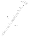
- Figure 1 illustrates one embodiment of a device 100 for brain stimulation.
- the device includes a lead 110, a plurality of electrodes 125 disposed at least partially about a circumference of the lead 110, a plurality of terminals 135, a connector 130 for connection of the electrodes to a control unit, and a stylet 140 for assisting in insertion and positioning of the lead in the patient's brain.
- the stylet 140 can be made of a rigid material. Examples of suitable materials for the stylet include, but are not limited to, tungsten, stainless steel, and plastic.
- the stylet 140 may have a handle 150 to assist insertion into the lead 110, as well as rotation of the stylet 140 and lead 110.
- the connector 130 fits over a proximal end of the lead 110, preferably after removal of the stylet 140.
- the control unit (not shown) is typically an implantable pulse generator that can be implanted into a patient's body, for example, below the patient's clavicle area.
- the pulse generator can have eight stimulation channels which may be independently programmable to control the magnitude of the current stimulus from each channel. In some cases the pulse generator may have more than eight stimulation channels (e.g., 16-, 32-, or more stimulation channels).
- the control unit may have one, two, three, four, or more connector ports, for receiving the plurality of terminals 135 at the proximal end of the lead 110.
- access to the desired position in the brain can be accomplished by drilling a hole in the patient's skull or cranium with a cranial drill (commonly referred to as a burr), and coagulating and incising the dura mater, or brain covering.
- the lead 110 can be inserted into the cranium and brain tissue with the assistance of the stylet 140.
- the lead 110 can be guided to the target location within the brain using, for example, a stereotactic frame and a microdrive motor system.
- the microdrive motor system can be fully or partially automatic.
- the microdrive motor system may be configured to perform one or more the following actions (alone or in combination): insert the lead 110, retract the lead 110, or rotate the lead 110.
- measurement devices coupled to the muscles or other tissues stimulated by the target neurons, or a unit responsive to the patient or clinician can be coupled to the control unit or microdrive motor system.
- the measurement device, user, or clinician can indicate a response by the target muscles or other tissues to the stimulation or recording electrode(s) to further identify the target neurons and facilitate positioning of the stimulation electrode(s).
- a measurement device can be used to observe the muscle and indicate changes in tremor frequency or amplitude in response to stimulation of neurons.
- the patient or clinician may observe the muscle and provide feedback.
- the lead 110 for deep brain stimulation can include stimulation electrodes, recording electrodes, or both.
- the lead 110 is rotatable so that the stimulation electrodes can be aligned with the target neurons after the neurons have been located using the recording electrodes.
- Stimulation electrodes may be disposed on the circumference of the lead 110 to stimulate the target neurons. Stimulation electrodes may be ring-shaped so that current projects from each electrode equally in every direction from the position of the electrode along a length of the lead 110. Ring electrodes, however, typically do not enable stimulus current to be directed to only one side of the lead. Segmented electrodes, however, can be used to direct stimulus current to one side, or even a portion of one side, of the lead. When segmented electrodes are used in conjunction with an implantable pulse generator that delivers constant current stimulus, current steering can be achieved to more precisely deliver the stimulus to a position around an axis of the lead ( i . e ., radial positioning around the axis of the lead).
- segmented electrodes can be utilized in addition to, or as an alternative to, ring electrodes. Though the following description discusses stimulation electrodes, it will be understood that all configurations of the stimulation electrodes discussed may be utilized in arranging recording electrodes as well.
- FIG. 2 illustrates one embodiment of a distal portion of a lead 200 for brain stimulation.
- the lead 200 includes a lead body 210, one or more optional ring electrodes 220, and a plurality of sets of segmented electrodes 230.
- the lead body 210 can be formed of a biocompatible, non-conducting material such as, for example, a polymeric material. Suitable polymeric materials include, but are not limited to, silicone, polyurethane, polyurea, polyurethane-urea, polyethylene, or the like.
- the lead 200 Once implanted in the body, the lead 200 may be in contact with body tissue for extended periods of time.
- the lead 200 has a cross-sectional diameter of no more than 1.5 mm and may be in the range of 1 to 1.5 mm.
- the lead 200 has a length of at least 10 cm and the length of the lead 200 may be in the range of 25 to 70 cm.
- the electrodes may be made using a metal, alloy, conductive oxide, or any other suitable conductive biocompatible material.
- suitable materials include, but are not limited to, platinum, platinum iridium alloy, iridium, titanium, tungsten, palladium, palladium rhodium, or the like.
- the electrodes are made of a material that is biocompatible and does not substantially corrode under expected operating conditions in the operating environment for the expected duration of use.
- Each of the electrodes can either be used or unused (OFF).
- the electrode can be used as an anode or cathode and carry anodic or cathodic current.
- an electrode might be an anode for a period of time and a cathode for a period of time.
- Stimulation electrodes in the form of ring electrodes 220 may be disposed on any part of the lead body 210, usually near a distal end of the lead 200.
- the lead 200 includes two ring electrodes 220. Any number of ring electrodes 220 may be disposed along the length of the lead body 210 including, for example, one, two three, four, five, six, seven, eight, nine, ten, eleven, twelve, thirteen, fourteen, fifteen, sixteen or more ring electrodes 220. It will be understood that any number of ring electrodes may be disposed along the length of the lead body 210.
- the ring electrodes 220 are substantially cylindrical and wrap around the entire circumference of the lead body 210.
- the outer diameters of the ring electrodes 220 are substantially equal to the outer diameter of the lead body 210.
- the length of the ring electrodes 220 may vary according to the desired treatment and the location of the target neurons. In some embodiments the length of the ring electrodes 220 are less than or equal to the diameters of the ring electrodes 220. In other embodiments, the lengths of the ring electrodes 220 are greater than the diameters of the ring electrodes 220.
- Deep brain stimulation leads may include one or more sets of segmented electrodes. Segmented electrodes may provide for superior current steering than ring electrodes because target structures in deep brain stimulation are not typically symmetric about the axis of the distal electrode array. Instead, a target may be located on one side of a plane running through the axis of the lead.
- RSEA radially segmented electrode array
- the lead 200 is shown having a plurality of segmented electrodes 230.
- Any number of segmented electrodes 230 may be disposed on the lead body 210 including, for example, one, two three, four, five, six, seven, eight, nine, ten, eleven, twelve, thirteen, fourteen, fifteen, sixteen or more segmented electrodes 230. It will be understood that any number of segmented electrodes 230 may be disposed along the length of the lead body 210.
- the segmented electrodes 230 may be grouped into sets of segmented electrodes, where each set is disposed around a circumference of the lead 200 at a particular longitudinal portion of the lead 200.
- the lead 200 may have any number segmented electrodes 230 in a given set of segmented electrodes.
- the lead 200 may have one, two, three, four, five, six, seven, eight, or more segmented electrodes 230 in a given set.
- each set of segmented electrodes 230 of the lead 200 contains the same number of segmented electrodes 230.
- the segmented electrodes 230 disposed on the lead 200 may include a different number of electrodes than at least one other set of segmented electrodes 230 disposed on the lead 200.
- the segmented electrodes 230 may vary in size and shape. In some embodiments, the segmented electrodes 230 are all of the same size, shape, diameter, width or area or any combination thereof. In some embodiments, the segmented electrodes 230 of each circumferential set (or even all segmented electrodes disposed on the lead 200) may be identical in size and shape.
- Each set of segmented electrodes 230 may be disposed around the circumference of the lead body 210 to form a substantially cylindrical shape around the lead body 210.
- the spacing between individual electrodes of a given set of the segmented electrodes may be the same, or different from, the spacing between individual electrodes of another set of segmented electrodes on the lead 200.
- equal spaces, gaps or cutouts are disposed between each segmented electrode 230 around the circumference of the lead body 210.
- the spaces, gaps or cutouts between the segmented electrodes 230 may differ in size or shape.
- the spaces, gaps, or cutouts between segmented electrodes 230 may be uniform for a particular set of the segmented electrodes 230, or for all sets of the segmented electrodes 230.
- the sets of segmented electrodes 230 may be positioned in irregular or regular intervals along a length the lead body 210.
- Conductor wires that attach to the ring electrodes 220 or segmented electrodes 230 extend along the lead body 210. These conductor wires may extend through the material of the lead 20 or along one or more lumens defined by the lead 200, or both. The conductor wires are presented at a connector (via terminals) for coupling of the electrodes 220, 230 to a control unit (not shown).
- the ring electrodes 220 and the segmented electrodes 230 may be arranged in any suitable configuration.
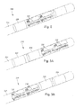
- the ring electrodes 220 can flank the two sets of segmented electrodes 230 (see e . g ., Figure 2 ).
- the two sets of ring electrodes 220 can be disposed proximal to the two sets of segmented electrodes 230 (see e.g., Figure 3A ), or the two sets of ring electrodes 220 can be disposed distal to the two sets of segmented electrodes 230 (see e.g ., Figure 3B ). It will be understood that other configurations are possible as well (e.g ., alternating ring and segmented electrodes, or the like).
- the electrode arrangement of Figure 3A may be useful if the physician anticipates that the neural target will be closer to a distal tip of the lead body 210, while the electrode arrangement of Figure 3B may be useful if the physician anticipates that the neural target will be closer to a proximal end of the lead body 210.
- any combination of ring electrodes 220 and segmented electrodes 230 may be disposed on the lead 200.
- the lead may include a first ring electrode 120, two sets of segmented electrodes, each set formed of three segmented electrodes 230, and a final ring electrode 120 at the end of the lead.
- This configuration may simply be referred to as a 1-3-3-1 configuration. It may be useful to refer to the electrodes with this shorthand notation.
- the embodiment of Figure 3A may be referred to as a 1-1-3-3 configuration
- the embodiment of Figure 3B may be referred to as a 3-3-1-1 configuration.
- Other eight-electrode configurations include, for example, a 2-2-2-2 configuration, where four sets of segmented electrodes are disposed on the lead, and a 4-4 configuration, where two sets of segmented electrodes, each having four segmented electrodes 230 are disposed on the lead.
- the lead includes 16 electrodes. Possible configurations for a 16-electrode lead include, but are not limited to 4-4-4-4; 8-8; 3-3-3-3-3-1 (and all rearrangements of this configuration); and 2-2-2-2-2-2-2-2-2-2.
- Figure 4 is a schematic diagram to illustrate radial current steering along various electrode levels along the length of the lead 200. While conventional lead configurations with ring electrodes are only able to steer current along the length of the lead (the z -axis), the segmented electrode configuration is capable of steering current in the x -axis, y -axis as well as the z -axis. Thus, the centroid of stimulation may be steered in any direction in the three-dimensional space surrounding the lead 200. In some embodiments, the radial distance, r , and the angle ⁇ around the circumference of the lead 200 may be dictated by the percentage of anodic current (recognizing that stimulation predominantly occurs near the cathode, although strong anodes may cause stimulation as well) introduced to each electrode. In at least some embodiments, the configuration of anodes and cathodes along the segmented electrodes allows the centroid of stimulation to be shifted to a variety of different locations along the lead 200.
- the centroid of stimulation can be shifted at each level along the length of the lead 200.
- the use of multiple sets of segmented electrodes at different levels along the length of the lead allows for three-dimensional current steering.
- the sets of segmented electrodes are shift collectively (i.e ., the centroid of simulation is similar at each level along the length of the lead).
- each set of segmented electrodes is controlled independently.
- Each set of segmented electrodes may contain two, three, four, five, six, seven, eight or more segmented electrodes. It will be understood that different stimulation profiles may be produced by varying the number of segmented electrodes at each level.
- each set of segmented electrodes includes only two segmented electrodes, uniformly distributed gaps (inability to stimulate selectively) may be formed in the stimulation profile.
- at least three segmented electrodes 230 in a set are utilized to allow for true 360° selectivity.
- measurement devices coupled to the muscles or other tissues stimulated by the target neurons or a unit responsive to the patient or clinician can be coupled to the control unit or microdrive motor system.
- the measurement device, user, or clinician can indicate a response by the target muscles or other tissues to the stimulation or recording electrodes to further identify the target neurons and facilitate positioning of the stimulation electrodes.
- a measurement device can be used to observe the muscle and indicate changes in tremor frequency or amplitude in response to stimulation of neurons.
- the patient or clinician may observe the muscle and provide feedback.
- the lead 200 When the lead 200 includes a plurality of sets of segmented electrodes 230, it may be desirable to form the lead 200 such that corresponding electrodes of different sets of segmented electrodes 230 are radially aligned with one another along the length of the lead 200 (see e.g., the segmented electrodes 230 shown in Figure 2 ). Radial alignment between corresponding electrodes of different sets of segmented electrodes 230 along the length of the lead 200 may reduce uncertainty as to the location or orientation between corresponding segmented electrodes of different sets of segmented electrodes. Accordingly, it may be beneficial to form electrode arrays such that corresponding electrodes of different segmented electrodes along the length of the lead 200 are radially aligned with one another and do not radially shift in relation to one another during manufacturing of the lead 200.
- Figure 5 is a side view of another embodiment of the lead 200 having a plurality of sets of segmented electrodes. As shown in Figure 5 , individual electrodes in the two sets of segmented electrodes 230 are staggered relative to one another along the length of the lead body 210. In some cases, the staggered positioning of corresponding electrodes of different sets of segmented electrodes along the length of the lead 200 may be designed for a specific application.
- Challenges to manufacturing leads with segmented electrodes include obtaining and maintaining the desired alignment of electrodes within a set of electrodes and between the set of electrodes. There may be challenges to maintaining a desired radial separation between electrodes of a set and axial separation between electrodes of different sets. In addition, there may be challenges to avoiding dislodgement of an electrode from the lead body.
- FIG. 6 is a flow diagram of a portion of one embodiment of a method of making a lead with segmented electrodes.
- a pre-electrode assembly with electrodes and raised connectors is provided.
- the pre-electrode assembly is a metal assembly with metal electrodes and metal connectors that couple the electrodes to each other.
- the electrodes and connectors are formed from a single sheet of metal.
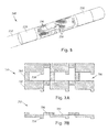
- FIGS 7A and 7B illustrate one embodiment of a pre-electrode assembly 700 with electrodes 702 and raised connectors 704.
- Each electrode 702 is directly coupled to at least one other electrode by at least one, two, or three of the raised connectors 704.
- the electrodes 702 are provided in a set of rows, in a set of columns, or in both rows and columns.
- the electrodes in a given row or column can be aligned with, or staggered with respect to, electrodes in an adjacent row or column.
- the electrodes in each row or column are directly coupled to the electrodes in an adjacent row or column using at least one, two, or three connectors.
- each electrode in a row or column is directly coupled by a connector to an electrode in an adjacent row or column
- the electrodes are arranged in rows and columns ar electrode is directly coupled by a connector to an electrode in an adjacent column and directly coupled by a connector to an electrode in an adjacent row, as illustrated, for example, in Figure 7A .
- the electrodes are arranged in rows and columns and each electrode is directly coupled by at least one connector to an electrode in each adjacent column and directly coupled by at least one connector to an electrode in each adjacent row, as illustrated, for example, in Figure 7A
- Figures 7A and 7B illustrate electrodes coupled to other electrodes using a single connector between two electrodes, it will be understood that multiple connectors can be used between two electrodes.
- the raised connectors 704 are provided to hold the electrodes 702 in alignment during the manufacture of the lead and will be removed during manufacture as described below.
- the electrodes 702 and connectors 704 are made of the same material.
- the electrodes 702 and connectors 704 are formed from a single sheet of metal.
- the pre-electrode assembly includes gaps 706 between the electrodes 702 and connectors 704.
- the connectors 704 are raised above the electrodes 702 by an amount greater than a thickness of the connectors 704 and may be raised at least twice, three times, four times, or ten times the thickness of the connectors 704. This can facilitate removal of the connectors later in the process of manufacturing.
- the connectors 704 can be any suitable size, width, length, and thickness.
- the length of the connectors 704 is the separation distance between the two electrodes coupled by the connector.
- the width and thickness can be selected to provide a desired amount of stability when maintaining the electrodes in the desired arrangement. It will be recognized that this factor is counterbalanced by the additional effort in forming a tube (see below) with a pre-electrode assembly with wider or thicker connectors; as well as the additional amount of material that will be removed with removal of the connectors.
- the width of the connector is no more than half, one-third, or one-quarter of the length of the connector. It will be recognized that the width and thickness of each of the connectors can be uniform or can vary along the length of the connectors. It will also be recognized that the connectors may have the same lengths, widths, and thicknesses or there may be variation in these parameters between connectors.
- the pre-electrode assembly 700 with electrodes 702 and connectors 704 can be formed by any suitable method.
- the pre-electrode assembly 700 can be formed by stamping a sheet of metal or other conductive material or by machining or molding metal or other conductive material into the desired shape.
- the stamping or molding of the pre-electrode assembly 700 results in the connectors 704 being raised with respect to the electrodes, as illustrated in Figures 7A and 7B .
- the connectors 704 can be raised in a separate step by, for example, stamping (e.g., a second stamping step) or otherwise bending the pre-electrode assembly to form the raised connectors.
- the gaps 706 between electrodes and between connectors may be formed when the pre-electrode assembly is formed by stamping or molding. Alternatively or additionally, some or all of the gaps may be formed prior to stamping or after stamping or molding; for example, the gaps may be formed by stamping, cutting, and the like.
- the electrodes 702 can include tabs 710.
- the tabs may be folded down during manufacture to interlock the electrodes with the material of the lead body described below.
- the tabs can protrude into the lead body and provide an anchoring mechanism to prevent dislodgment of the individual electrode segments.
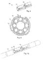
- the pre-electrode assembly is formed into a tube, as illustrated, for example, in Figure 8 .
- the pre-electrode assembly 700 is wrapped around a mandrel or other cylindrical element to facilitate formation of the tube.
- the pre-electrode assembly 700 is wrapped around a lead tube 712 that includes a central lumen 714 and optionally one or more conductor lumens 716 as illustrated, for example, in Figure 9 .
- the embodiments illustrated in Figures 8 and 9 show a tube with a circular cross-section, it will be understood that other types of tubes can be formed including, but not limited to, tubes with square, rectangular, oval, triangular, hexagonal, or octagonal cross-sections.
- the pre-electrode assembly can be formed or rolled into a cylinder.
- the tube formed by the pre-electrode assembly defines a longitudinal axis along the tube.
- each of the raised connectors is disposed at a radius with respect to the longitudinal axis that is greater than a radius of any of the electrodes.
- the pre-electrode assembly can be held in the cylindrical form by any suitable method.
- straps or fasteners may be attached to the pre-electrode ass wrapped around the pre-electrode assembly, to hold it in the cylindrical form.
- two or more portions of the pre-electrode assembly may overlap and the overlapping regions of the carrier can be attached to each other by welding, soldering, application of adhesive, or the like.
- the forming process will cause the metal to yield and hence the material will take a permanent change in shape by, for example, deformation of the material.
- conductor wires are attached to the individual electrodes 402 before or after forming the pre-electrode assembly into a tube.
- the conductor wires can be, for example, insulated wires with a portion of the insulation removed to make contact with the electrodes 702.
- a different conductor wire can be attached to each electrode 702. In other embodiments, the same conductor wire may be attached to two or more of the electrodes.
- the conductor wires can be attached by any suitable method including, but not limited to, welding, soldering, crimping, staking, using a conductive adhesive, and the like.
- the conductor wires can be attached to any suitable part of the electrodes 702.
- the conductor wires are disposed in conductor lumens 716 (see, e.g., Figure 9 ).
- One or more conductor wires may be disposed in each conductor lumen.
- each conductor lumen has a single conductor wire disposed therein. Portions of the conductor lumens can be exposed (e.g., by ablating or removing a portion of the lead tube) to provide access for attachment of the conductor wire to the electrode.
- step 606 at least a portion of the lead body is formed around the pre-electrode assembly.
- Figure 10 illustrates one embodiment of the pre-electrode assembly 700 with a portion 720 of the lead body formed around the electrodes 702 and connectors 704 of the pre-electrode assembly.
- Figure 11 is a cross-sectional view illustrating the electrodes 702 and connectors 704 with a portion 720 of the lead body. As illustrated in Figure 11 , preferably a portion of the lead body 720 is formed beneath the connectors 704.
- the portion of the lead body that is formed is capable of retaining the electrodes 702 within the lead and in the desired orientation and configuration after removal of the connectors, as described below.
- the formation of the lead body may also incorporate other electrodes, such as ring electrodes 722, into the structure of the lead.
- the portion of the lead body may incorporate pre-structures, such as the lead tube 712 of Figure 9 , into the lead body during its formation as illustrated, for example, in Figure 11 .
- the portion of the lead body can be formed by any suitable method including, but not limited to, molding the portion of the lead body around the pre-electrode assembly.
- polymeric material such as polymer tubing (e.g., polyurethane or silicone tubing)
- polymer tubing e.g., polyurethane or silicone tubing
- a heat shrink tube may be temporarily placed over the polymer tubing, prior to reflow, so that the material of the polymer tubing is retained during reflow. The heat shrink tubing may then be removed (e.g., cut off) after reflow of the polymer tubing.
- the connectors are removed by grinding.
- Figures 2 and 12 illustrate embodiments of a lead after removal of the connectors.
- the connectors are removed by centerless grinding.
- the grinding may also remove portions of the lead body, the electrodes, or both.
- the grinding provides a lead that is isodiametric at the distal end or along the entire lead.
Landscapes
- Health & Medical Sciences (AREA)
- Nuclear Medicine, Radiotherapy & Molecular Imaging (AREA)
- Life Sciences & Earth Sciences (AREA)
- Veterinary Medicine (AREA)
- Cardiology (AREA)
- Heart & Thoracic Surgery (AREA)
- Engineering & Computer Science (AREA)
- Neurosurgery (AREA)
- Biomedical Technology (AREA)
- Radiology & Medical Imaging (AREA)
- Neurology (AREA)
- Animal Behavior & Ethology (AREA)
- General Health & Medical Sciences (AREA)
- Public Health (AREA)
- Psychology (AREA)
- Orthopedic Medicine & Surgery (AREA)
- Electrotherapy Devices (AREA)
Applications Claiming Priority (3)
| Application Number | Priority Date | Filing Date | Title |
|---|---|---|---|
| US201061426784P | 2010-12-23 | 2010-12-23 | |
| PCT/US2011/056582 WO2012087416A1 (fr) | 2010-12-23 | 2011-10-17 | Procédés de fabrication de dérivations avec des électrodes segmentées pour des systèmes de stimulation électrique |
| EP11774168.6A EP2654876B1 (fr) | 2010-12-23 | 2011-10-17 | Procédé et un ensemble pour fabriquer un conducteur médical comprenant l'enlèvement par abrasion de connecteurs en saillie |
Related Parent Applications (1)
| Application Number | Title | Priority Date | Filing Date |
|---|---|---|---|
| EP11774168.6A Division EP2654876B1 (fr) | 2010-12-23 | 2011-10-17 | Procédé et un ensemble pour fabriquer un conducteur médical comprenant l'enlèvement par abrasion de connecteurs en saillie |
Publications (2)
| Publication Number | Publication Date |
|---|---|
| EP2881139A1 true EP2881139A1 (fr) | 2015-06-10 |
| EP2881139B1 EP2881139B1 (fr) | 2021-10-06 |
Family
ID=44860569
Family Applications (2)
| Application Number | Title | Priority Date | Filing Date |
|---|---|---|---|
| EP11774168.6A Not-in-force EP2654876B1 (fr) | 2010-12-23 | 2011-10-17 | Procédé et un ensemble pour fabriquer un conducteur médical comprenant l'enlèvement par abrasion de connecteurs en saillie |
| EP14194738.2A Not-in-force EP2881139B1 (fr) | 2010-12-23 | 2011-10-17 | Procédé et un ensemble pour fabriquer un conducteur médical comprenant l'enlèvement de connecteurs par abrasion |
Family Applications Before (1)
| Application Number | Title | Priority Date | Filing Date |
|---|---|---|---|
| EP11774168.6A Not-in-force EP2654876B1 (fr) | 2010-12-23 | 2011-10-17 | Procédé et un ensemble pour fabriquer un conducteur médical comprenant l'enlèvement par abrasion de connecteurs en saillie |
Country Status (7)
| Country | Link |
|---|---|
| US (2) | US8862242B2 (fr) |
| EP (2) | EP2654876B1 (fr) |
| JP (1) | JP5889917B2 (fr) |
| AU (1) | AU2011345291B2 (fr) |
| CA (1) | CA2822343A1 (fr) |
| ES (1) | ES2530959T3 (fr) |
| WO (1) | WO2012087416A1 (fr) |
Families Citing this family (209)
| Publication number | Priority date | Publication date | Assignee | Title |
|---|---|---|---|---|
| US7860570B2 (en) | 2002-06-20 | 2010-12-28 | Boston Scientific Neuromodulation Corporation | Implantable microstimulators and methods for unidirectional propagation of action potentials |
| US8321025B2 (en) | 2006-07-31 | 2012-11-27 | Cranial Medical Systems, Inc. | Lead and methods for brain monitoring and modulation |
| US7583999B2 (en) | 2006-07-31 | 2009-09-01 | Cranial Medical Systems, Inc. | Multi-channel connector for brain stimulation system |
| ES2615402T3 (es) | 2007-03-19 | 2017-06-06 | Boston Scientific Neuromodulation Corporation | Cables compatibles con IRM y RF |
| JP5568316B2 (ja) | 2007-03-19 | 2014-08-06 | ボストン サイエンティフィック ニューロモデュレイション コーポレイション | Mri/rf適合リード線、および関連のリード線を操作、作製する方法 |
| EP3173125B1 (fr) | 2008-07-30 | 2019-03-27 | Ecole Polytechnique Fédérale de Lausanne | Appareil de stimulation optimisée d'une cible neurologique |
| US8359107B2 (en) | 2008-10-09 | 2013-01-22 | Boston Scientific Neuromodulation Corporation | Electrode design for leads of implantable electric stimulation systems and methods of making and using |
| EP3231476B1 (fr) | 2008-11-12 | 2019-06-19 | Ecole Polytechnique Fédérale de Lausanne | Dispositif de neurostimulation microfabriqué |
| US8473061B2 (en) | 2009-04-16 | 2013-06-25 | Boston Scientific Neuromodulation Corporation | Deep brain stimulation current steering with split electrodes |
| US8887387B2 (en) | 2009-07-07 | 2014-11-18 | Boston Scientific Neuromodulation Corporation | Methods of manufacture of leads with a radially segmented electrode array |
| US8875391B2 (en) * | 2009-07-07 | 2014-11-04 | Boston Scientific Neuromodulation Corporation | Methods for making leads with radially-aligned segmented electrodes for electrical stimulation systems |
| US8788063B2 (en) * | 2009-11-30 | 2014-07-22 | Boston Scientific Neuromodulation Corporation | Electrode array having a rail system and methods of manufacturing the same |
| US8295944B2 (en) | 2009-11-30 | 2012-10-23 | Boston Scientific Neuromodulation Corporation | Electrode array with electrodes having cutout portions and methods of making the same |
| US8874232B2 (en) | 2009-11-30 | 2014-10-28 | Boston Scientific Neuromodulation Corporation | Electrode array having concentric split ring electrodes and methods of making the same |
| US8391985B2 (en) | 2009-11-30 | 2013-03-05 | Boston Scientific Neuromodulation Corporation | Electrode array having concentric windowed cylinder electrodes and methods of making the same |
| JP5927176B2 (ja) | 2010-04-01 | 2016-06-01 | エコーレ ポリテクニーク フェデラーレ デ ローザンヌ (イーピーエフエル) | 神経組織と相互作用するためのデバイス、ならびにそれを作製および使用する方法 |
| US8868206B2 (en) | 2010-06-18 | 2014-10-21 | Boston Scientific Neuromodulation Corporation | Electrode array having embedded electrodes and methods of making the same |
| US8583237B2 (en) | 2010-09-13 | 2013-11-12 | Cranial Medical Systems, Inc. | Devices and methods for tissue modulation and monitoring |
| AU2011305914B2 (en) | 2010-09-21 | 2016-05-12 | Boston Scientific Neuromodulation Corporation | Systems and methods for making and using radially-aligned segmented electrodes for leads of electrical stimulation systems |
| EP2654876B1 (fr) | 2010-12-23 | 2014-12-10 | Boston Scientific Neuromodulation Corporation | Procédé et un ensemble pour fabriquer un conducteur médical comprenant l'enlèvement par abrasion de connecteurs en saillie |
| US8700179B2 (en) * | 2011-02-02 | 2014-04-15 | Boston Scientific Neuromodulation Corporation | Leads with spiral of helical segmented electrode arrays and methods of making and using the leads |
| US20120203316A1 (en) | 2011-02-08 | 2012-08-09 | Boston Scientific Neuromodulation Corporation | Leads with segmented electrodes for electrical stimulation of planar regions and methods of making and using |
| WO2012109331A1 (fr) | 2011-02-08 | 2012-08-16 | Boston Scientific Neuromodulation Corporation | Conducteurs à électrodes segmentées disposées en spirale et procédés de fabrication et d'utilisation des conducteurs |
| US8886335B2 (en) | 2011-12-07 | 2014-11-11 | Boston Scientific Neuromodulation Corporation | Implantable leads with a low profile distal portion |
| JP5908611B2 (ja) | 2012-01-26 | 2016-04-26 | ボストン サイエンティフィック ニューロモデュレイション コーポレイション | 電気刺激システムのためのリードの電極の周方向位置決めを識別するためのシステム及び方法 |
| WO2013148092A1 (fr) | 2012-03-30 | 2013-10-03 | Boston Scientific Neuromodulation Corporation | Dérivations à capsules fluorescentes de rayons x pour identification d'électrode et procédés de fabrication ainsi que leur utilisation |
| US9827413B2 (en) | 2012-04-17 | 2017-11-28 | Boston Scientific Neuromodulation Corporation | Lead construction for deep brain stimulation |
| US9878148B2 (en) | 2012-04-17 | 2018-01-30 | Boston Scientific Neuromodulation Corporation | Lead with contact end conductor guide and methods of making and using |
| WO2013162775A2 (fr) * | 2012-04-27 | 2013-10-31 | Medtronic, Inc. | Structures et techniques pour la fabrication d'un conducteur médical |
| US20130317587A1 (en) | 2012-05-25 | 2013-11-28 | Boston Scientific Neuromodulation Corporation | Methods for stimulating the dorsal root ganglion with a lead having segmented electrodes |
| AU2013266290B2 (en) | 2012-05-25 | 2016-03-10 | Boston Scientific Neuromodulation Corporation | Percutaneous implantation of an electrical stimulation lead for stimulating dorsal root ganglion |
| US8768488B2 (en) | 2012-05-25 | 2014-07-01 | Boston Scientific Neuromodulation Corporation | Systems and methods for electrically stimulating patient tissue on or around one or more bony structures |
| US9919148B2 (en) | 2012-05-25 | 2018-03-20 | Boston Scientific Neuromodulation Corporation | Distally curved electrical stimulation lead and methods of making and using |
| AU2013267240B2 (en) | 2012-06-01 | 2016-04-28 | Boston Scientific Neuromodulation Corporation | Leads with tip electrode for electrical stimulation systems and methods of making and using |
| US8897891B2 (en) | 2012-08-03 | 2014-11-25 | Boston Scientific Neuromodulation Corporation | Leads with electrode carrier for segmented electrodes and methods of making and using |
| WO2014089213A1 (fr) * | 2012-12-06 | 2014-06-12 | Boston Scientific Neuromodulation Corporation | Systèmes et procédés de formation d'ensembles contact pour fils de systèmes de stimulation électrique |
| EP2968933B1 (fr) | 2013-03-15 | 2019-06-12 | Boston Scientific Neuromodulation Corporation | Systèmes pour administrer une thérapie infraliminaire à un patient |
| EP2996765B1 (fr) | 2013-05-15 | 2019-06-26 | Boston Scientific Neuromodulation Corporation | Électrodes à pointe pour sondes de systèmes de stimulation électrique |
| AU2014274414A1 (en) | 2013-05-31 | 2015-11-19 | Boston Scientific Neuromodulation Corporation | Leads with segmented electrodes and methods of making the leads |
| US9498620B2 (en) | 2013-05-31 | 2016-11-22 | Boston Scientific Neuromodulation Corporation | Leads containing segmented electrodes with non-perpendicular legs and methods of making and using |
| EP3003468B1 (fr) | 2013-05-31 | 2019-08-28 | Boston Scientific Neuromodulation Corporation | Procédé de fabrication de conducteurs d'électrodes segmentées au moyen d'un anneau amovible et conducteurs formés par celui-ci |
| EP3003465A1 (fr) | 2013-05-31 | 2016-04-13 | Boston Scientific Neuromodulation Corporation | Fils d'électrode segmentés formés à partir de pré-électrodes munies des dépressions ou d'ouvertures et procédé de fabrication |
| JP2016519985A (ja) | 2013-05-31 | 2016-07-11 | ボストン サイエンティフィック ニューロモデュレイション コーポレイション | 整列特徴部を有するプレ電極から形成されたセグメント電極リード及びリードの製造方法及び使用方法 |
| JP6072986B2 (ja) | 2013-07-12 | 2017-02-01 | ボストン サイエンティフィック ニューロモデュレイション コーポレイション | セグメント電極を備えたリード並びにリードの製造及び使用方法 |
| US9655528B2 (en) | 2013-07-15 | 2017-05-23 | Boston Scientific Neuromodulation Corporation | Systems and methods for detecting cerebrospinal-fluid pulsation using an implantable electrical stimulation device |
| WO2015013071A1 (fr) | 2013-07-22 | 2015-01-29 | Boston Scientific Neuromodulation Corporation | Procédés de fabrication de fils d'électrodes segmentés moulés |
| US9302113B2 (en) | 2013-07-29 | 2016-04-05 | Boston Scientific Neuromodulation Corporation | Systems and methods for identifying anode placement based on cerebrospinal fluid thickness |
| US9089689B2 (en) | 2013-08-30 | 2015-07-28 | Boston Scientific Neuromodulation Corporation | Methods of making segmented electrode leads using flanged carrier |
| EP3077039B1 (fr) | 2013-12-02 | 2021-10-13 | Boston Scientific Neuromodulation Corporation | Procédés pour le fabrication des sondes pour la stimulation électrique avec électrodes arrangées en hélice |
| US9440066B2 (en) | 2014-01-27 | 2016-09-13 | Boston Scientific Neuromodulation Corporation | Systems and methods for making and using connector assemblies for implantable medical device systems |
| EP3142745B1 (fr) | 2014-05-16 | 2018-12-26 | Aleva Neurotherapeutics SA | Dispositif pour l'interaction avec un tissu neurologique |
| US11311718B2 (en) | 2014-05-16 | 2022-04-26 | Aleva Neurotherapeutics Sa | Device for interacting with neurological tissue and methods of making and using the same |
| WO2015192058A1 (fr) | 2014-06-13 | 2015-12-17 | Boston Scientific Neuromodulation Corporation | Sondes comprenant des supports d'électrode pour des électrodes segmentées, et procédés de fabrication et d'utilisation |
| CA2954855C (fr) * | 2014-07-24 | 2020-08-18 | Boston Scientific Neuromodulation Corporation | Stimulation de corne dorsale amelioree a l'aide de multiples champs electriques |
| US9474894B2 (en) | 2014-08-27 | 2016-10-25 | Aleva Neurotherapeutics | Deep brain stimulation lead |
| US9770598B2 (en) | 2014-08-29 | 2017-09-26 | Boston Scientific Neuromodulation Corporation | Systems and methods for making and using improved connector contacts for electrical stimulation systems |
| EP3197548A1 (fr) | 2014-09-22 | 2017-08-02 | Boston Scientific Neuromodulation Corporation | Dispositifs utilisant une fréquence pathologique en stimulation électrique pour une gestion de la douleur |
| EP3197547A1 (fr) | 2014-09-22 | 2017-08-02 | Boston Scientific Neuromodulation Corporation | Systèmes et procédés pour administrer une thérapie à un patient à l'aide d'une stimulation électrique intermittente |
| EP3197546A2 (fr) | 2014-09-22 | 2017-08-02 | Boston Scientific Neuromodulation Corporation | Systèmes et méthodes à visée thérapeutique utilisant la stimulation électrique pour interrompre l'activité neuronale |
| EP4000684B1 (fr) | 2014-09-22 | 2025-05-07 | Boston Scientific Neuromodulation Corporation | Dispositifs d'utilisation d'un spectre d'énergie ou d'une association de signaux pour la gestion de la douleur |
| US9925377B2 (en) | 2014-09-22 | 2018-03-27 | Boston Scientific Neuromodulation Corporation | Systems and methods for providing therapy using electrical stimulation to disrupt neuronal activity |
| EP3200845B1 (fr) | 2014-09-30 | 2021-04-28 | Boston Scientific Scimed, Inc. | Conception de ballonnet à deux couches, et son procédé de fabrication |
| EP3204112A1 (fr) | 2014-10-07 | 2017-08-16 | Boston Scientific Neuromodulation Corporation | Systèmes, dispositifs et procédés de stimulation électrique à l'aide d'une rétroaction pour régler des paramètres de stimulation |
| US20160121103A1 (en) | 2014-11-03 | 2016-05-05 | Boston Scientific Neuromodulation Corporation | Electrical stimulation system with anchoring stylet and methods of making and using |
| US9604068B2 (en) | 2014-11-10 | 2017-03-28 | Boston Scientific Neuromodulation Corporation | Systems and methods for making and using improved connector contacts for electrical stimulation systems |
| US9561362B2 (en) | 2014-11-10 | 2017-02-07 | Boston Scientific Neuromodulation Corporation | Systems and methods for making and using improved contact arrays for electrical stimulation systems |
| US10286205B2 (en) | 2015-02-06 | 2019-05-14 | Boston Scientific Neuromodulation Corporation | Systems and methods for making and using improved contact arrays for electrical stimulation systems |
| WO2016164361A1 (fr) | 2015-04-10 | 2016-10-13 | Boston Scientific Neuromodulation Corporation | Systèmes et procédés de fabrication et d'utilisation de réseaux de contact améliorés pour des systèmes de stimulation électrique |
| US9364659B1 (en) | 2015-04-27 | 2016-06-14 | Dantam K. Rao | Smart lead for deep brain stimulation |
| EP3268082B1 (fr) | 2015-05-26 | 2019-04-17 | Boston Scientific Neuromodulation Corporation | Systèmes et procédés d'analyse de stimulation électrique et de sélection ou de manipulation de volumes d'activation |
| US20160375248A1 (en) | 2015-06-29 | 2016-12-29 | Boston Scientific Neuromodulation Corporation | Systems and methods for selecting stimulation parameters based on stimulation target region, effects, or side effects |
| ES2940303T3 (es) | 2015-06-29 | 2023-05-05 | Boston Scient Neuromodulation Corp | Sistemas de selección de parámetros de estimulación por uso de dianas y direccionamiento |
| US9656093B2 (en) | 2015-07-16 | 2017-05-23 | Boston Scientific Neuromodulation Corporation | Systems and methods for making and using connector contact arrays for electrical stimulation systems |
| US10232169B2 (en) | 2015-07-23 | 2019-03-19 | Boston Scientific Neuromodulation Corporation | Burr hole plugs for electrical stimulation systems and methods of making and using |
| WO2017035158A1 (fr) | 2015-08-24 | 2017-03-02 | Boston Scientific Neuromodulation Corporation | Systèmes et procédés permettant de déterminer l'orientation d'une dérivation de stimulation électrique |
| EP3297719B1 (fr) | 2015-09-01 | 2022-02-09 | Boston Scientific Neuromodulation Corporation | Détection d'orientation de câble |
| US9956394B2 (en) | 2015-09-10 | 2018-05-01 | Boston Scientific Neuromodulation Corporation | Connectors for electrical stimulation systems and methods of making and using |
| US10413737B2 (en) | 2015-09-25 | 2019-09-17 | Boston Scientific Neuromodulation Corporation | Systems and methods for providing therapy using electrical stimulation to disrupt neuronal activity |
| US10071249B2 (en) | 2015-10-09 | 2018-09-11 | Boston Scientific Neuromodulation Corporation | System and methods for clinical effects mapping for directional stimulation leads |
| US9986989B2 (en) | 2016-01-08 | 2018-06-05 | Boston Scientific Neuromodulation Corporation | Surgical retractor for implanting leads and methods of making and using |
| US10342983B2 (en) | 2016-01-14 | 2019-07-09 | Boston Scientific Neuromodulation Corporation | Systems and methods for making and using connector contact arrays for electrical stimulation systems |
| CN109069824B (zh) | 2016-02-02 | 2022-09-16 | 阿莱瓦神经治疗股份有限公司 | 使用深部脑刺激治疗自身免疫疾病 |
| AU2017214317B2 (en) | 2016-02-05 | 2019-08-22 | Boston Scientfic Neuromodulation Corporation | Implantable optical stimulation lead |
| US10814127B2 (en) | 2016-02-05 | 2020-10-27 | Boston Scientific Neuromodulation Corporation | Slotted sleeve neurostimulation device |
| AU2017220115B2 (en) | 2016-02-19 | 2019-11-21 | Boston Scientific Neuromodulation Corporation | Electrical stimulation cuff devices and systems |
| WO2017151438A1 (fr) | 2016-02-29 | 2017-09-08 | Boston Scientific Neuromodulation Corporation | Point d'ancrage de conducteur électrique pour système de stimulation électrique |
| US10124161B2 (en) | 2016-03-31 | 2018-11-13 | Boston Scientific Neuromodulation Corporation | Neurostimulation lead with conductive elements and methods for making the same |
| US10716942B2 (en) | 2016-04-25 | 2020-07-21 | Boston Scientific Neuromodulation Corporation | System and methods for directional steering of electrical stimulation |
| US10369354B2 (en) | 2016-05-17 | 2019-08-06 | Boston Scientific Neuromodulation Corporation | Systems and method for anchoring a lead for neurostimulation of a target anatomy |
| US10493269B2 (en) | 2016-06-02 | 2019-12-03 | Boston Scientific Neuromodulation Corporation | Leads for electrostimulation of peripheral nerves and other targets |
| US10201713B2 (en) | 2016-06-20 | 2019-02-12 | Boston Scientific Neuromodulation Corporation | Threaded connector assembly and methods of making and using the same |
| WO2017223505A2 (fr) | 2016-06-24 | 2017-12-28 | Boston Scientific Neuromodulation Corporation | Systèmes et procédés pour l'analyse visuelle d'effets cliniques |
| US10307602B2 (en) | 2016-07-08 | 2019-06-04 | Boston Scientific Neuromodulation Corporation | Threaded connector assembly and methods of making and using the same |
| EP3458154B1 (fr) | 2016-07-29 | 2025-11-12 | Boston Scientific Neuromodulation Corporation | Ensemble connecteur avec des anneaux de contact comprenant des contacts à ressort précontraint, pourvus de billes respectives |
| US10709888B2 (en) | 2016-07-29 | 2020-07-14 | Boston Scientific Neuromodulation Corporation | Systems and methods for making and using an electrical stimulation system for peripheral nerve stimulation |
| US10780274B2 (en) | 2016-08-22 | 2020-09-22 | Boston Scientific Neuromodulation Corporation | Systems and methods for delivering spinal cord stimulation therapy |
| WO2018044881A1 (fr) | 2016-09-02 | 2018-03-08 | Boston Scientific Neuromodulation Corporation | Systèmes et procédés de visualisation et d'orientation de la stimulation d'éléments neuronaux |
| US10780282B2 (en) | 2016-09-20 | 2020-09-22 | Boston Scientific Neuromodulation Corporation | Systems and methods for steering electrical stimulation of patient tissue and determining stimulation parameters |
| US10543374B2 (en) | 2016-09-30 | 2020-01-28 | Boston Scientific Neuromodulation Corporation | Connector assemblies with bending limiters for electrical stimulation systems and methods of making and using same |
| EP3493876B1 (fr) | 2016-10-14 | 2021-03-17 | Boston Scientific Neuromodulation Corporation | Systèmes destinés à la détermination en boucle fermée des réglages de paramètres de stimulation destinés à un système de stimulation électrique |
| WO2018071842A1 (fr) | 2016-10-14 | 2018-04-19 | Boston Scientific Neuromodulation Corporation | Systèmes et procédés permettant de déterminer l'orientation d'un fil implanté |
| US10525257B2 (en) | 2016-10-14 | 2020-01-07 | Boston Scientific Neuromodulation Corporation | Orientation marker for implantable leads and leads, systems, and methods utilizing the orientation marker |
| US10625072B2 (en) | 2016-10-21 | 2020-04-21 | Boston Scientific Neuromodulation Corporation | Electrical stimulation methods with optical observation and devices therefor |
| US10716935B2 (en) | 2016-11-04 | 2020-07-21 | Boston Scientific Neuromodulation Corporation | Electrical stimulation leads, systems and methods for stimulation of dorsal root ganglia |
| US10603485B2 (en) | 2016-11-28 | 2020-03-31 | Boston Scientific Neuromodulation Corporation | Features in increased surface area on neuromodulation leads |
| EP3548140B1 (fr) | 2016-12-02 | 2022-04-20 | Boston Scientific Neuromodulation Corporation | Systèmes permettant de sélectionner des paramètres de stimulation pour des dispositifs de stimulation électrique |
| AU2017391436B2 (en) | 2017-01-03 | 2020-06-18 | Boston Scientific Neuromodulation Corporation | Systems and methods for selecting MRI-compatible stimulation parameters |
| US10576269B2 (en) | 2017-01-03 | 2020-03-03 | Boston Scientific Neuromodulation Corporation | Force-decoupled and strain relieving lead and methods of making and using |
| EP3568196B1 (fr) | 2017-01-10 | 2023-11-29 | Boston Scientific Neuromodulation Corporation | Stimulation à motifs pour stimulation cérébrale profonde |
| US10589104B2 (en) | 2017-01-10 | 2020-03-17 | Boston Scientific Neuromodulation Corporation | Systems and methods for creating stimulation programs based on user-defined areas or volumes |
| US10905871B2 (en) | 2017-01-27 | 2021-02-02 | Boston Scientific Neuromodulation Corporation | Lead assemblies with arrangements to confirm alignment between terminals and contacts |
| US10814136B2 (en) | 2017-02-28 | 2020-10-27 | Boston Scientific Neuromodulation Corporation | Toolless connector for latching stimulation leads and methods of making and using |
| US10709886B2 (en) | 2017-02-28 | 2020-07-14 | Boston Scientific Neuromodulation Corporation | Electrical stimulation leads and systems with elongate anchoring elements and methods of making and using |
| US10625082B2 (en) | 2017-03-15 | 2020-04-21 | Boston Scientific Neuromodulation Corporation | Visualization of deep brain stimulation efficacy |
| US10835739B2 (en) | 2017-03-24 | 2020-11-17 | Boston Scientific Neuromodulation Corporation | Electrical stimulation leads and systems with elongate anchoring elements and methods of making and using |
| US11357986B2 (en) | 2017-04-03 | 2022-06-14 | Boston Scientific Neuromodulation Corporation | Systems and methods for estimating a volume of activation using a compressed database of threshold values |
| US10603499B2 (en) | 2017-04-07 | 2020-03-31 | Boston Scientific Neuromodulation Corporation | Tapered implantable lead and connector interface and methods of making and using |
| US10631937B2 (en) | 2017-04-14 | 2020-04-28 | Boston Scientific Neuromodulation Corporation | Systems and methods for determining orientation of an implanted electrical stimulation lead |
| US10857351B2 (en) | 2017-04-28 | 2020-12-08 | Boston Scientific Neuromodulation Corporation | Lead anchors for electrical stimulation leads and systems and methods of making and using |
| US20180333173A1 (en) | 2017-05-22 | 2018-11-22 | Boston Scientific Neuromodulation Corporation | Systems and methods for making and using a lead introducer for an electrical stimulation system |
| US20180369606A1 (en) | 2017-06-26 | 2018-12-27 | Boston Scientific Neuromodulation Corporationd | Systems and methods for making and using implantable optical stimulation leads and assemblies |
| US10814140B2 (en) | 2017-06-26 | 2020-10-27 | Boston Scientific Neuromodulation Corporation | Systems and methods for visualizing and controlling optogenetic stimulation using optical stimulation systems |
| EP3651849B1 (fr) | 2017-07-14 | 2023-05-31 | Boston Scientific Neuromodulation Corporation | Estimation des effets cliniques d'une stimulation électrique |
| WO2019014217A1 (fr) | 2017-07-14 | 2019-01-17 | Boston Scientific Neuromodulation Corporation | Systèmes et procédés de planification et de programmation de stimulation électrique |
| US10918873B2 (en) | 2017-07-25 | 2021-02-16 | Boston Scientific Neuromodulation Corporation | Systems and methods for making and using an enhanced connector of an electrical stimulation system |
| US10960214B2 (en) | 2017-08-15 | 2021-03-30 | Boston Scientific Neuromodulation Corporation | Systems and methods for controlling electrical stimulation using multiple stimulation fields |
| US11219759B2 (en) | 2017-08-29 | 2022-01-11 | Boston Scientific Neuromodulation Corporation | Systems and methods for introducing an electrical stimulation lead into a patient |
| US10953221B2 (en) | 2017-08-30 | 2021-03-23 | Medtronic, Inc. | Medical lead with segmented electrodes |
| CN111629778B (zh) | 2017-09-15 | 2024-07-26 | 波士顿科学神经调制公司 | 手术室线缆组件的偏置引线连接器及其制造和使用方法 |
| WO2019055837A1 (fr) | 2017-09-15 | 2019-03-21 | Boston Scientific Neuromodulation Corporation | Connecteur de fil actionnable pour ensemble câble de salle d'opération et procédés de fabrication et d'utilisation |
| US11139603B2 (en) | 2017-10-03 | 2021-10-05 | Boston Scientific Neuromodulation Corporation | Connectors with spring contacts for electrical stimulation systems and methods of making and using same |
| US11103716B2 (en) | 2017-11-13 | 2021-08-31 | Boston Scientific Neuromodulation Corporation | Systems and methods for making and using a low-profile control module for an electrical stimulation system |
| WO2019099887A1 (fr) | 2017-11-17 | 2019-05-23 | Boston Scientific Neuromodulation Corporation | Systèmes et procédés pour produire une stimulation intermittente au moyen de systèmes de stimulation électrique |
| US10967192B2 (en) | 2017-12-29 | 2021-04-06 | Boston Scientific Neuromodulation Corporation | Systems and methods for charging a medical device implanted into a patient |
| EP3737464B1 (fr) | 2018-01-11 | 2026-02-25 | Boston Scientific Neuromodulation Corporation | Systèmes de stimulation pour la modulation gliale |
| US11103712B2 (en) | 2018-01-16 | 2021-08-31 | Boston Scientific Neuromodulation Corporation | Connector assemblies with novel spacers for electrical stimulation systems and methods of making and using same |
| WO2019143574A1 (fr) | 2018-01-16 | 2019-07-25 | Boston Scientific Neuromodulation Corporation | Système de stimulation électrique avec une batterie au boîtier neutre et module de commande pour un tel système |
| US11357544B2 (en) | 2018-01-25 | 2022-06-14 | Boston Scientific Neuromodulation Corporation | Systems and methods for introducing a stimulation lead into a patient |
| US10702692B2 (en) | 2018-03-02 | 2020-07-07 | Aleva Neurotherapeutics | Neurostimulation device |
| US11058870B2 (en) | 2018-03-09 | 2021-07-13 | Boston Scientific Neuromodulation Corporation | Burr hole plugs for electrical stimulation systems and methods of making and using |
| US11013913B2 (en) | 2018-03-16 | 2021-05-25 | Boston Scientific Neuromodulation Corporation | Kits and methods for securing a burr hole plugs for stimulation systems |
| US20210008389A1 (en) | 2018-03-23 | 2021-01-14 | Boston Scientific Neuromodulation Corporation | Optical stimulation system with automated monitoring and methods of making and using |
| WO2019183054A1 (fr) | 2018-03-23 | 2019-09-26 | Boston Scientific Neuromodulation Corporation | Systèmes de stimulation optique avec étalonnage et procédés de fabrication et d'utilisation |
| EP3768372A1 (fr) | 2018-03-23 | 2021-01-27 | Boston Scientific Neuromodulation Corporation | Système de stimulation optique doté d'une surveillance à la demande et procédés de fabrication et d'utilisation |
| WO2019183078A1 (fr) | 2018-03-23 | 2019-09-26 | Boston Scientific Neuromodulation Corporation | Systèmes de stimulation optique utilisant des cycles de thérapie et procédés d'utilisation |
| WO2019183082A1 (fr) | 2018-03-23 | 2019-09-26 | Boston Scientific Neuromodulation Corporation | Prothèses implantables pour réduire la visibilité d'un bombement à partir de dispositifs médicaux implantés |
| JP7295141B2 (ja) | 2018-04-27 | 2023-06-20 | ボストン サイエンティフィック ニューロモデュレイション コーポレイション | マルチモード電気刺激システム及び製造する及び使用する方法 |
| EP3784332B1 (fr) | 2018-04-27 | 2023-04-26 | Boston Scientific Neuromodulation Corporation | Systèmes de visualisation et de programmation de la stimulation électrique |
| US11172959B2 (en) | 2018-05-02 | 2021-11-16 | Boston Scientific Neuromodulation Corporation | Long, flexible sheath and lead blank and systems and methods of making and using |
| EP3790623B1 (fr) | 2018-05-11 | 2023-07-05 | Boston Scientific Neuromodulation Corporation | Ensemble connecteur pour un système de stimulation électrique |
| AU2019302442B2 (en) | 2018-07-09 | 2022-06-30 | Boston Scientific Neuromodulation Corporation | Directional electrical stimulation leads and systems for spinal cord stimulation |
| US11224743B2 (en) | 2018-09-21 | 2022-01-18 | Boston Scientific Neuromodulation Corporation | Systems and methods for making and using modular leads for electrical stimulation systems |
| US11167128B2 (en) | 2018-11-16 | 2021-11-09 | Boston Scientific Neuromodulation Corporation | Directional electrical stimulation leads, systems and methods for spinal cord stimulation |
| AU2019378702B2 (en) | 2018-11-16 | 2022-09-01 | Boston Scientific Neuromodulation Corporation | An optical stimulation system with on-demand monitoring and methods of making |
| AU2020226356B2 (en) | 2019-02-19 | 2022-12-08 | Boston Scientific Neuromodulation Corporation | Lead introducers and systems and methods including the lead introducers |
| WO2020205843A1 (fr) | 2019-04-01 | 2020-10-08 | Boston Scientific Neuromodulation Corporation | Systèmes et procédés de fabrication et d'utilisation d'un module de commande peu encombrant pour un système de stimulation électrique |
| US11357992B2 (en) | 2019-05-03 | 2022-06-14 | Boston Scientific Neuromodulation Corporation | Connector assembly for an electrical stimulation system and methods of making and using |
| AU2020282967B2 (en) | 2019-05-30 | 2023-04-13 | Boston Scientific Neuromodulation Corporation | Methods and systems for discrete measurement of electrical characteristics |
| US11623095B2 (en) | 2019-06-20 | 2023-04-11 | Boston Scientific Neuromodulation Corporation | Methods and systems for interleaving waveforms for electrical stimulation and measurement |
| EP3965865B1 (fr) | 2019-07-26 | 2024-03-06 | Boston Scientific Neuromodulation Corporation | Méthodes et systèmes de stockage, d'extraction et de visualisation des signaux et des caractéristiques des signaux |
| AU2020323899B2 (en) | 2019-07-26 | 2023-06-01 | Boston Scientific Neuromodulation Corporation | Methods and systems for making electrical stimulation adjustments based on patient-specific factors |
| US20220362560A1 (en) | 2019-10-28 | 2022-11-17 | Boston Scientific Neuromodulation Corporation | Systems and methods for measuring temperature on or near an implantable medical device |
| EP4076625A1 (fr) | 2020-02-19 | 2022-10-26 | Boston Scientific Neuromodulation Corporation | Méthodes et systèmes pour le traitement de l'insomnie faisant intervenir la stimulation cérébrale profonde |
| EP4168110B1 (fr) | 2020-09-04 | 2025-09-24 | Boston Scientific Neuromodulation Corporation | Systèmes de stimulation ayant un agencement de lentilles pour couplage de lumière |
| EP4196209A1 (fr) | 2020-11-04 | 2023-06-21 | Boston Scientific Neuromodulation Corporation | Procédés et systèmes de gestion d'accès à des dispositifs médicaux implantables |
| WO2022103590A1 (fr) | 2020-11-11 | 2022-05-19 | Boston Scientific Neuromodulation Corporation | Gestionnaire de commande vocale pour la programmation de systèmes de stimulation et procédés d'utilisation |
| JP7641390B2 (ja) | 2021-01-19 | 2025-03-06 | ボストン サイエンティフィック ニューロモデュレイション コーポレイション | 指向性電極構成を有する電気刺激カフデバイス及びシステム |
| WO2022182892A1 (fr) | 2021-02-25 | 2022-09-01 | Boston Scientific Neuromodulation Corporation | Procédés et systèmes de stimulation cérébrale profonde du noyau basal de meynert |
| US12427332B2 (en) | 2021-04-08 | 2025-09-30 | Boston Scientific Neuromodulation Corporation | Photobiomodulation system and delivery device and methods of making and using |
| US12403315B2 (en) | 2021-04-27 | 2025-09-02 | Boston Scientific Neuromodulation Corporation | Systems and methods for automated programming of electrical stimulation |
| EP4313262B1 (fr) | 2021-05-21 | 2025-04-02 | Boston Scientific Neuromodulation Corporation | Dispositifs de stimulation électrique |
| WO2022261001A1 (fr) | 2021-06-07 | 2022-12-15 | Boston Scientific Neuromodulation Corporation | Systèmes de stimulation ayant des routines spécifiées par l'utilisateur et procédés de fabrication et d'utilisation |
| EP4313268B1 (fr) | 2021-06-07 | 2026-04-01 | Boston Scientific Neuromodulation Corporation | Systèmes d'équilibrage de charge de stimulation électrique |
| WO2022265977A1 (fr) | 2021-06-15 | 2022-12-22 | Boston Scientific Neuromodulation Corporation | Procédés et systèmes d'estimation d'activation neuronale par stimulation à l'aide d'un système de stimulation |
| WO2022271837A1 (fr) * | 2021-06-23 | 2022-12-29 | Medtronic, Inc. | Sondes médicales implantables ayant des segments d'électrode de différentes tailles |
| US12589252B2 (en) | 2021-08-19 | 2026-03-31 | Boston Scientific Neuromodulation Corporation | Connector assembly with capacitive contacts for an electrical stimulation system and methods of making and using |
| US12343547B2 (en) | 2021-08-19 | 2025-07-01 | Boston Scientific Neuromodulation Corporation | Connectors for an electrical stimulation system and methods of making and using |
| US12527956B2 (en) | 2021-12-09 | 2026-01-20 | Boston Scientific Neuromodulation Corporation | Methods and systems for monitoring or assessing movement disorders or other physiological parameters using a stimulation system |
| US12471831B2 (en) | 2021-12-10 | 2025-11-18 | Boston Scientific Neuromodulation Corporation | Systems and methods for generating and using response maps for electrical stimulation |
| WO2023107444A1 (fr) | 2021-12-10 | 2023-06-15 | Boston Scientific Neuromodulation Corporation | Procédés et systèmes pour déterminer et utiliser un indice d'intensité pour une stimulation électrique |
| AU2023218273C1 (en) | 2022-02-10 | 2026-04-02 | Boston Scientific Neuromodulation Corporation | Automatic therapy adjustment based on sensors |
| US12350487B2 (en) | 2022-02-16 | 2025-07-08 | Advanced Neuromodulation Systems, Inc. | Methods for fabricating segmented electrodes |
| EP4440687A1 (fr) | 2022-02-24 | 2024-10-09 | Boston Scientific Neuromodulation Corporation | Systèmes et procédés d'utilisation de paramètres de coût pour programmer une stimulation électrique |
| WO2023167872A1 (fr) | 2022-03-02 | 2023-09-07 | Boston Scientific Neuromodulation Corporation | Systèmes et procédés de surveillance de dérive de stimulation dans un système de stimulation électrique |
| WO2024044050A1 (fr) | 2022-08-22 | 2024-02-29 | Boston Scientific Neuromodulation Corporation | Systèmes de photobiomodulation implantables utilisant une surveillance ou une commande thermique et procédés de fabrication et d'utilisation |
| EP4565319A1 (fr) | 2022-08-22 | 2025-06-11 | Boston Scientific Neuromodulation Corporation | Systèmes de photobiomodulation comprenant une électrode disposée sur ou tout prés un émetteur de lumière et procédés de fabrication et d'utilisation |
| EP4368242A1 (fr) | 2022-11-14 | 2024-05-15 | Boston Scientific Neuromodulation Corporation | Systèmes et procédés de génération et d'utilisation de programmes de stimulation avec variation temporelle |
| WO2024129609A1 (fr) | 2022-12-14 | 2024-06-20 | Boston Scientific Neuromodulation Corporation | Systèmes et procédés de surveillance et de révision de stimulation électrique |
| WO2024141768A2 (fr) | 2022-12-29 | 2024-07-04 | Benabid Alim Louis | Systèmes de stimulation optique et procédés d'implantation et d'utilisation |
| EP4398258A3 (fr) | 2023-01-04 | 2024-08-28 | Boston Scientific Neuromodulation Corporation | Systèmes et procédés incorporant une interface utilisateur de photothérapie pour modulation optique |
| EP4646260A1 (fr) | 2023-03-22 | 2025-11-12 | Boston Scientific Neuromodulation Corporation | Systèmes pour déplacer une stimulation à l'aide de commandes directionnelles anatomiques |
| US20240359015A1 (en) | 2023-04-28 | 2024-10-31 | Boston Scientific Neuromodulation Corporation | Systems and methods for modifying stimulation in response to a change in a symptom, therapeutic effect, or side effect |
| US20250010079A1 (en) | 2023-07-06 | 2025-01-09 | Boston Scientific Neuromodulation Corporation | Systems and methods for selecting electrodes and providing stimulation |
| WO2025034507A1 (fr) | 2023-08-10 | 2025-02-13 | Boston Scientific Neuromodulation Corporation | Amélioration de la neuromodulation pour le sommeil |
| EP4735105A2 (fr) | 2023-08-11 | 2026-05-06 | Boston Scientific Neuromodulation Corporation | Procédés et systèmes de commande et de modification de stimulation |
| WO2025038718A1 (fr) | 2023-08-16 | 2025-02-20 | Boston Scientific Neuromodulation Corporation | Photobiomodulation de cerveau antérieur basal pour améliorer la cognition |
| US20250058107A1 (en) | 2023-08-16 | 2025-02-20 | Boston Scientific Neuromodulation Corporation | Integration of related probability shells into deep brain stimulation targeting |
| AU2024324981A1 (en) | 2023-08-16 | 2026-02-05 | Boston Scientific Neuromodulation Corporation | Integration of fiber tracts into deep brain stimulation targeting |
| WO2025054405A1 (fr) | 2023-09-07 | 2025-03-13 | Boston Scientific Neuromodulation Corporation | Système et méthode de modulation de synchronisation neuronale |
| US20250082945A1 (en) | 2023-09-13 | 2025-03-13 | Boston Scientific Neuromodulation Corporation | Coiled ring contacts for electrical stimulation systems and methods of making and using same |
| US20250099749A1 (en) | 2023-09-21 | 2025-03-27 | Boston Scientific Neuromodulation Corporation | Electrical stimulation cuff devices and systems and electrode arrangements therefor |
| WO2025075826A1 (fr) | 2023-10-02 | 2025-04-10 | Boston Scientific Neuromodulation Corporation | Introducteurs de fil conducteur et systèmes comprenant les introducteurs de fil conducteur |
| WO2025096870A1 (fr) | 2023-11-02 | 2025-05-08 | Boston Scientific Neuromodulation Corporation | Optimisation de programme dbs au moyen d'une sélection prédéfinie de contacts |
| EP4552688A3 (fr) | 2023-11-09 | 2025-05-28 | Boston Scientific Neuromodulation Corporation | Systèmes de photobiomodulation utilisant une surveillance ou une stimulation électrique et procédés de fabrication et d'utilisation |
| US20250242159A1 (en) | 2024-01-30 | 2025-07-31 | Boston Scientific Neuromodulation Corporation | System and method for combined photobiomodulation and electrical stimulation for epilepsy |
| US20250367448A1 (en) | 2024-06-04 | 2025-12-04 | Boston Scientific Neuromodulation Corporation | Systems and methods for evoked signal sensing using adjustable dc offset compensation |
| US20260014370A1 (en) | 2024-07-09 | 2026-01-15 | Boston Scientific Neuromodulation Corporation | Electrical stimulation cuff leads and systems and methods of making and using |
| WO2026019846A1 (fr) | 2024-07-17 | 2026-01-22 | Boston Scientific Neuromodulation Corporation | Systèmes et procédés de programmation et de visualisation de stimulation nerveuse périphérique |
| US20260069860A1 (en) | 2024-09-06 | 2026-03-12 | Boston Scientific Neuromodulation Corporation | Systems and methods for peripheral nerve stimulation using microbursts or nerve mapping paradigms |
Citations (10)
| Publication number | Priority date | Publication date | Assignee | Title |
|---|---|---|---|---|
| US20060168805A1 (en) * | 2005-01-31 | 2006-08-03 | Michael Hegland | Method of manufacturing a medical lead |
| US20070150036A1 (en) | 2005-12-27 | 2007-06-28 | Advanced Bionics Corporation | Stimulator leads and methods for lead fabrication |
| US20070219551A1 (en) * | 2003-09-22 | 2007-09-20 | Honour Kirk S | Medical device with flexible printed circuit |
| US20080114230A1 (en) * | 2006-11-14 | 2008-05-15 | Bruce Addis | Electrode support |
| US20090187222A1 (en) | 2008-01-23 | 2009-07-23 | Boston Scientific Neuromodulation Corporation | Steerable stylet handle assembly |
| US20090276021A1 (en) | 2008-04-30 | 2009-11-05 | Boston Scientific Neuromodulation Corporation | Electrodes for stimulation leads and methods of manufacture and use |
| US20100030298A1 (en) * | 2006-09-26 | 2010-02-04 | Koninklijke Philips Electronics N.V. | Tissue stimulation method and apparatus |
| US20100076535A1 (en) | 2008-09-25 | 2010-03-25 | Boston Scientific Neuromodulation Corporation | Leads with non-circular-shaped distal ends for brain stimulation systems and methods of making and using |
| US20100077606A1 (en) * | 1999-04-26 | 2010-04-01 | Damon Ray Black | Method of forming a lead |
| US7809446B2 (en) | 2005-01-05 | 2010-10-05 | Boston Scientific Neuromodulation Corporation | Devices and methods for brain stimulation |
Family Cites Families (100)
| Publication number | Priority date | Publication date | Assignee | Title |
|---|---|---|---|---|
| US2295308A (en) | 1938-02-26 | 1942-09-08 | Gen Electric | High speed reclosing mechanism |
| US4630611A (en) | 1981-02-02 | 1986-12-23 | Medtronic, Inc. | Orthogonally-sensing lead |
| US4602624A (en) | 1984-10-11 | 1986-07-29 | Case Western Reserve University | Implantable cuff, method of manufacture, and method of installation |
| US4744370A (en) | 1987-04-27 | 1988-05-17 | Cordis Leads, Inc. | Lead assembly with selectable electrode connection |
| US5000194A (en) | 1988-08-25 | 1991-03-19 | Cochlear Corporation | Array of bipolar electrodes |
| US5135001A (en) | 1990-12-05 | 1992-08-04 | C. R. Bard, Inc. | Ultrasound sheath for medical diagnostic instruments |
| EP0580928A1 (fr) | 1992-07-31 | 1994-02-02 | ARIES S.r.l. | Cathéter pour électrode spinale |
| ZA948393B (en) | 1993-11-01 | 1995-06-26 | Polartechnics Ltd | Method and apparatus for tissue type recognition |
| US5458629A (en) | 1994-02-18 | 1995-10-17 | Medtronic, Inc. | Implantable lead ring electrode and method of making |
| US5522874A (en) | 1994-07-28 | 1996-06-04 | Gates; James T. | Medical lead having segmented electrode |
| DE69734065D1 (de) | 1996-03-07 | 2005-09-29 | Axon Engineering Inc | Polymer-metall folienstruktur für neuronale stimulationselektroden |
| US5713922A (en) | 1996-04-25 | 1998-02-03 | Medtronic, Inc. | Techniques for adjusting the locus of excitation of neural tissue in the spinal cord or brain |
| US5711316A (en) | 1996-04-30 | 1998-01-27 | Medtronic, Inc. | Method of treating movement disorders by brain infusion |
| US5843148A (en) | 1996-09-27 | 1998-12-01 | Medtronic, Inc. | High resolution brain stimulation lead and method of use |
| US5938688A (en) | 1997-10-22 | 1999-08-17 | Cornell Research Foundation, Inc. | Deep brain stimulation method |
| US6161047A (en) | 1998-04-30 | 2000-12-12 | Medtronic Inc. | Apparatus and method for expanding a stimulation lead body in situ |
| US6134478A (en) | 1998-06-05 | 2000-10-17 | Intermedics Inc. | Method for making cardiac leads with zone insulated electrodes |
| US6322559B1 (en) | 1998-07-06 | 2001-11-27 | Vnus Medical Technologies, Inc. | Electrode catheter having coil structure |
| US6018684A (en) * | 1998-07-30 | 2000-01-25 | Cardiac Pacemakers, Inc. | Slotted pacing/shocking electrode |
| US6564078B1 (en) | 1998-12-23 | 2003-05-13 | Nuvasive, Inc. | Nerve surveillance cannula systems |
| EP1146816B1 (fr) | 1998-12-23 | 2005-10-12 | Nuvasive Inc. | Systemes de catheter et de surveillance de nerfs |
| US6167311A (en) | 1999-06-14 | 2000-12-26 | Electro Core Techniques, Llc | Method of treating psychological disorders by brain stimulation within the thalamus |
| US7047082B1 (en) * | 1999-09-16 | 2006-05-16 | Micronet Medical, Inc. | Neurostimulating lead |
| US6556873B1 (en) | 1999-11-29 | 2003-04-29 | Medtronic, Inc. | Medical electrical lead having variable bending stiffness |
| DE60131952T2 (de) | 2000-02-09 | 2008-12-18 | Medtronic Transneuronix, Inc. | Medizinische implantierbare vorrichtung zur elektrostimulation mit diskreten mikroelektroden |
| US6510347B2 (en) | 2000-08-17 | 2003-01-21 | William N. Borkan | Spinal cord stimulation leads |
| US6757970B1 (en) | 2000-11-07 | 2004-07-06 | Advanced Bionics Corporation | Method of making multi-contact electrode array |
| WO2002045795A2 (fr) | 2000-12-07 | 2002-06-13 | Medtronic, Inc. | Stimulation directionnelle du cerveau et broches de raccordement |
| GB0104982D0 (en) | 2001-02-28 | 2001-04-18 | Gill Steven | Electrode |
| CA2443782A1 (fr) * | 2001-05-07 | 2002-11-14 | Dusan Milojevic | Procede de fabrication de composants electroconducteurs |
| US6678564B2 (en) | 2001-12-06 | 2004-01-13 | Advanced Cochlear Systems, Inc. | Bio-implant and method of making the same |
| US8000802B2 (en) | 2002-04-22 | 2011-08-16 | Medtronic, Inc. | Implantable lead with coplanar contact coupling |
| US7027852B2 (en) | 2002-05-21 | 2006-04-11 | Pacesetter, Inc. | Lead with distal tip surface electrodes connected in parallel |
| US7203548B2 (en) | 2002-06-20 | 2007-04-10 | Advanced Bionics Corporation | Cavernous nerve stimulation via unidirectional propagation of action potentials |
| US7292890B2 (en) | 2002-06-20 | 2007-11-06 | Advanced Bionics Corporation | Vagus nerve stimulation via unidirectional propagation of action potentials |
| US7860570B2 (en) | 2002-06-20 | 2010-12-28 | Boston Scientific Neuromodulation Corporation | Implantable microstimulators and methods for unidirectional propagation of action potentials |
| US7047084B2 (en) | 2002-11-20 | 2006-05-16 | Advanced Neuromodulation Systems, Inc. | Apparatus for directionally stimulating nerve tissue |
| US20050038489A1 (en) | 2003-08-14 | 2005-02-17 | Grill Warren M. | Electrode array for use in medical stimulation and methods thereof |
| WO2005053789A2 (fr) | 2003-11-25 | 2005-06-16 | Advanced Neuromodulation Systems, Inc. | Fil de stimulation directionnelle et systeme d'orientation, aiguille amelioree d'insertion percutanee et procede d'implantation du fil electrique |
| US7489971B1 (en) | 2004-06-05 | 2009-02-10 | Advanced Neuromodulation Systems, Inc. | Notched electrode for electrostimulation lead |
| EP1786509A4 (fr) | 2004-07-27 | 2010-01-13 | Cleveland Clinic Foundation | Dispositif de stimulation thalamique |
| JP5112879B2 (ja) * | 2004-12-22 | 2013-01-09 | プロテウス デジタル ヘルス, インコーポレイテッド | インプラント可能であり、アドレス可能であるセグメント化された電極 |
| US20080077186A1 (en) | 2006-04-18 | 2008-03-27 | Proteus Biomedical, Inc. | High phrenic, low capture threshold pacing devices and methods |
| US8019439B2 (en) * | 2005-01-11 | 2011-09-13 | Boston Scientific Neuromodulation Corporation | Lead assembly and method of making same |
| US8066702B2 (en) | 2005-01-11 | 2011-11-29 | Rittman Iii William J | Combination electrical stimulating and infusion medical device and method |
| US8565898B2 (en) | 2005-04-28 | 2013-10-22 | Medtronic, Inc. | Rate control during AF using cellular intervention to modulate AV node |
| US7822482B2 (en) | 2005-07-29 | 2010-10-26 | Medtronic, Inc. | Electrical stimulation lead with rounded array of electrodes |
| US7848802B2 (en) | 2006-02-24 | 2010-12-07 | Medtronic, Inc. | Programming interface with a concentric axial view of a stimulation lead with complex electrode array geometry |
| US7822483B2 (en) | 2006-02-24 | 2010-10-26 | Medtronic, Inc. | Electrical and activation field models for configuring stimulation therapy |
| DE602006009712D1 (de) | 2006-03-02 | 2009-11-19 | St Jude Medical | Medizinische implantierbare leitung und verfahren zu ihrer herstellung |
| US8321025B2 (en) | 2006-07-31 | 2012-11-27 | Cranial Medical Systems, Inc. | Lead and methods for brain monitoring and modulation |
| EP2059294B1 (fr) | 2006-08-07 | 2018-10-10 | Alpha Omega Neuro Technologies Ltd. | Electrodes cerebrales |
| US20080103580A1 (en) | 2006-10-31 | 2008-05-01 | Medtronic, Inc. | Implantable medical elongated member with dual purpose conduit |
| US7684873B2 (en) | 2006-10-31 | 2010-03-23 | Medtronic, Inc. | Implantable medical lead including a directional electrode and fixation elements along an interior surface |
| EP2078263B1 (fr) | 2006-10-31 | 2019-06-12 | Semiconductor Energy Laboratory Co, Ltd. | Dispositif semi-conducteur |
| US7979140B2 (en) | 2006-12-12 | 2011-07-12 | Alfred E. Mann Foundation For Scientific Research | Segmented electrode |
| WO2008072125A1 (fr) | 2006-12-13 | 2008-06-19 | Koninklijke Philips Electronics, N.V. | Premier placement correct d'une dérivation de la stimulation cérébrale profonde |
| RU2467773C2 (ru) | 2007-03-02 | 2012-11-27 | Сапиенс Стиринг Брейн Стимьюлейшн Б.В. | Система электродов для глубокой стимуляции головного мозга |
| US7668601B2 (en) | 2007-04-26 | 2010-02-23 | Medtronic, Inc. | Implantable medical lead with multiple electrode configurations |
| US20090054947A1 (en) | 2007-08-20 | 2009-02-26 | Medtronic, Inc. | Electrode configurations for directional leads |
| US9220889B2 (en) | 2008-02-11 | 2015-12-29 | Intelect Medical, Inc. | Directional electrode devices with locating features |
| US8019440B2 (en) | 2008-02-12 | 2011-09-13 | Intelect Medical, Inc. | Directional lead assembly |
| US8688235B1 (en) | 2008-07-22 | 2014-04-01 | Boston Scientific Neuromodulation Corporation | Lead with transition and methods of manufacture and use |
| US8335551B2 (en) | 2008-09-29 | 2012-12-18 | Chong Il Lee | Method and means for connecting a large number of electrodes to a measuring device |
| US8359107B2 (en) | 2008-10-09 | 2013-01-22 | Boston Scientific Neuromodulation Corporation | Electrode design for leads of implantable electric stimulation systems and methods of making and using |
| EP3231476B1 (fr) | 2008-11-12 | 2019-06-19 | Ecole Polytechnique Fédérale de Lausanne | Dispositif de neurostimulation microfabriqué |
| JP2012508624A (ja) | 2008-11-13 | 2012-04-12 | プロテウス バイオメディカル インコーポレイテッド | 多重化複数電極神経刺激装置 |
| US8473061B2 (en) | 2009-04-16 | 2013-06-25 | Boston Scientific Neuromodulation Corporation | Deep brain stimulation current steering with split electrodes |
| US8250755B2 (en) | 2009-04-24 | 2012-08-28 | Advanced Neuromodulation Systems, Inc. | Process for fabricating a medical lead |
| US8225504B2 (en) | 2009-04-24 | 2012-07-24 | Advanced Neuromodulation Systems, Inc. | Medical leads with segmented electrodes and methods of fabrication thereof |
| US8046909B2 (en) | 2009-04-24 | 2011-11-01 | Advanced Neuromodulation Systems, Inc. | Method of fabricating stimulation lead |
| US20100287770A1 (en) | 2009-05-14 | 2010-11-18 | Cochlear Limited | Manufacturing an electrode carrier for an implantable medical device |
| US8875391B2 (en) | 2009-07-07 | 2014-11-04 | Boston Scientific Neuromodulation Corporation | Methods for making leads with radially-aligned segmented electrodes for electrical stimulation systems |
| US8887387B2 (en) | 2009-07-07 | 2014-11-18 | Boston Scientific Neuromodulation Corporation | Methods of manufacture of leads with a radially segmented electrode array |
| US20110047795A1 (en) | 2009-09-01 | 2011-03-03 | Kevin Turner | Medical leads with segmented electrodes and methods of fabrication thereof |
| US20110077699A1 (en) | 2009-09-30 | 2011-03-31 | John Swanson | Medical leads with segmented electrodes and methods of fabrication thereof |
| US8295944B2 (en) | 2009-11-30 | 2012-10-23 | Boston Scientific Neuromodulation Corporation | Electrode array with electrodes having cutout portions and methods of making the same |
| US8874232B2 (en) | 2009-11-30 | 2014-10-28 | Boston Scientific Neuromodulation Corporation | Electrode array having concentric split ring electrodes and methods of making the same |
| US8788063B2 (en) | 2009-11-30 | 2014-07-22 | Boston Scientific Neuromodulation Corporation | Electrode array having a rail system and methods of manufacturing the same |
| US8391985B2 (en) | 2009-11-30 | 2013-03-05 | Boston Scientific Neuromodulation Corporation | Electrode array having concentric windowed cylinder electrodes and methods of making the same |
| US8571665B2 (en) | 2010-03-23 | 2013-10-29 | Boston Scientific Neuromodulation Corporation | Helical radial spacing of contacts on a cylindrical lead |
| US9162053B2 (en) | 2010-04-02 | 2015-10-20 | Boston Scientific Neuromodulation Corporation | Directional lead assembly |
| US8868206B2 (en) | 2010-06-18 | 2014-10-21 | Boston Scientific Neuromodulation Corporation | Electrode array having embedded electrodes and methods of making the same |
| WO2012009181A2 (fr) | 2010-07-16 | 2012-01-19 | Boston Scientific Neuromodulation Corporation | Systèmes et procédés pour la direction radiale de groupements d'électrodes |
| US20120046710A1 (en) | 2010-08-18 | 2012-02-23 | Boston Scientific Neuromodulation Corporation | Methods, systems, and devices for deep brain stimulation using helical movement of the centroid of stimulation |
| US8583237B2 (en) | 2010-09-13 | 2013-11-12 | Cranial Medical Systems, Inc. | Devices and methods for tissue modulation and monitoring |
| AU2011305914B2 (en) | 2010-09-21 | 2016-05-12 | Boston Scientific Neuromodulation Corporation | Systems and methods for making and using radially-aligned segmented electrodes for leads of electrical stimulation systems |
| EP2654876B1 (fr) | 2010-12-23 | 2014-12-10 | Boston Scientific Neuromodulation Corporation | Procédé et un ensemble pour fabriquer un conducteur médical comprenant l'enlèvement par abrasion de connecteurs en saillie |
| US8700179B2 (en) | 2011-02-02 | 2014-04-15 | Boston Scientific Neuromodulation Corporation | Leads with spiral of helical segmented electrode arrays and methods of making and using the leads |
| US20120203316A1 (en) | 2011-02-08 | 2012-08-09 | Boston Scientific Neuromodulation Corporation | Leads with segmented electrodes for electrical stimulation of planar regions and methods of making and using |
| JP2014511227A (ja) | 2011-02-08 | 2014-05-15 | ボストン サイエンティフィック ニューロモデュレイション コーポレイション | 電気刺激システムのためのセグメント電極を有するリードを製造する方法 |
| WO2012109331A1 (fr) | 2011-02-08 | 2012-08-16 | Boston Scientific Neuromodulation Corporation | Conducteurs à électrodes segmentées disposées en spirale et procédés de fabrication et d'utilisation des conducteurs |
| US9138576B2 (en) | 2011-10-28 | 2015-09-22 | Medtronic, Inc. | Lead end having inner support |
| JP5908611B2 (ja) | 2012-01-26 | 2016-04-26 | ボストン サイエンティフィック ニューロモデュレイション コーポレイション | 電気刺激システムのためのリードの電極の周方向位置決めを識別するためのシステム及び方法 |
| WO2013148092A1 (fr) | 2012-03-30 | 2013-10-03 | Boston Scientific Neuromodulation Corporation | Dérivations à capsules fluorescentes de rayons x pour identification d'électrode et procédés de fabrication ainsi que leur utilisation |
| WO2013162775A2 (fr) | 2012-04-27 | 2013-10-31 | Medtronic, Inc. | Structures et techniques pour la fabrication d'un conducteur médical |
| US20130317587A1 (en) | 2012-05-25 | 2013-11-28 | Boston Scientific Neuromodulation Corporation | Methods for stimulating the dorsal root ganglion with a lead having segmented electrodes |
| AU2013267240B2 (en) | 2012-06-01 | 2016-04-28 | Boston Scientific Neuromodulation Corporation | Leads with tip electrode for electrical stimulation systems and methods of making and using |
| US9555234B2 (en) | 2012-07-26 | 2017-01-31 | Medtronic, Inc. | Implantable medical leads |
| US8897891B2 (en) | 2012-08-03 | 2014-11-25 | Boston Scientific Neuromodulation Corporation | Leads with electrode carrier for segmented electrodes and methods of making and using |
-
2011
- 2011-10-17 EP EP11774168.6A patent/EP2654876B1/fr not_active Not-in-force
- 2011-10-17 WO PCT/US2011/056582 patent/WO2012087416A1/fr not_active Ceased
- 2011-10-17 JP JP2013546138A patent/JP5889917B2/ja not_active Expired - Fee Related
- 2011-10-17 ES ES11774168T patent/ES2530959T3/es active Active
- 2011-10-17 US US13/275,112 patent/US8862242B2/en active Active
- 2011-10-17 AU AU2011345291A patent/AU2011345291B2/en not_active Ceased
- 2011-10-17 EP EP14194738.2A patent/EP2881139B1/fr not_active Not-in-force
- 2011-10-17 CA CA2822343A patent/CA2822343A1/fr not_active Abandoned
-
2014
- 2014-09-09 US US14/481,749 patent/US9295830B2/en active Active
Patent Citations (10)
| Publication number | Priority date | Publication date | Assignee | Title |
|---|---|---|---|---|
| US20100077606A1 (en) * | 1999-04-26 | 2010-04-01 | Damon Ray Black | Method of forming a lead |
| US20070219551A1 (en) * | 2003-09-22 | 2007-09-20 | Honour Kirk S | Medical device with flexible printed circuit |
| US7809446B2 (en) | 2005-01-05 | 2010-10-05 | Boston Scientific Neuromodulation Corporation | Devices and methods for brain stimulation |
| US20060168805A1 (en) * | 2005-01-31 | 2006-08-03 | Michael Hegland | Method of manufacturing a medical lead |
| US20070150036A1 (en) | 2005-12-27 | 2007-06-28 | Advanced Bionics Corporation | Stimulator leads and methods for lead fabrication |
| US20100030298A1 (en) * | 2006-09-26 | 2010-02-04 | Koninklijke Philips Electronics N.V. | Tissue stimulation method and apparatus |
| US20080114230A1 (en) * | 2006-11-14 | 2008-05-15 | Bruce Addis | Electrode support |
| US20090187222A1 (en) | 2008-01-23 | 2009-07-23 | Boston Scientific Neuromodulation Corporation | Steerable stylet handle assembly |
| US20090276021A1 (en) | 2008-04-30 | 2009-11-05 | Boston Scientific Neuromodulation Corporation | Electrodes for stimulation leads and methods of manufacture and use |
| US20100076535A1 (en) | 2008-09-25 | 2010-03-25 | Boston Scientific Neuromodulation Corporation | Leads with non-circular-shaped distal ends for brain stimulation systems and methods of making and using |
Also Published As
| Publication number | Publication date |
|---|---|
| AU2011345291A1 (en) | 2013-07-11 |
| CA2822343A1 (fr) | 2012-06-28 |
| JP2014502897A (ja) | 2014-02-06 |
| WO2012087416A1 (fr) | 2012-06-28 |
| US20140379061A1 (en) | 2014-12-25 |
| US9295830B2 (en) | 2016-03-29 |
| EP2654876A1 (fr) | 2013-10-30 |
| EP2881139B1 (fr) | 2021-10-06 |
| US20120165911A1 (en) | 2012-06-28 |
| JP5889917B2 (ja) | 2016-03-22 |
| AU2011345291B2 (en) | 2016-05-12 |
| EP2654876B1 (fr) | 2014-12-10 |
| ES2530959T3 (es) | 2015-03-09 |
| US8862242B2 (en) | 2014-10-14 |
Similar Documents
| Publication | Publication Date | Title |
|---|---|---|
| EP2654876B1 (fr) | Procédé et un ensemble pour fabriquer un conducteur médical comprenant l'enlèvement par abrasion de connecteurs en saillie | |
| EP3498333B1 (fr) | Fils avec électrodes segmentées disposées en spirale et procédés de fabrication et d'utilisation de fils | |
| US9248276B2 (en) | Leads with spiral of helical segmented electrode arrays and methods of making and using the leads | |
| EP3024535B1 (fr) | Procédés de fabrication de fils d'électrodes segmentés moulés | |
| EP3003468B1 (fr) | Procédé de fabrication de conducteurs d'électrodes segmentées au moyen d'un anneau amovible et conducteurs formés par celui-ci | |
| EP3003469B1 (fr) | Conducteurs contenant des électrodes segmentées pourvues de pattes non perpendiculaires et procédés de fabrication et d'utilisation desdits conducteurs | |
| US9248272B2 (en) | Segmented electrode leads formed from pre-electrodes with depressions or apertures and methods of making and using | |
| US9227050B2 (en) | Leads with electrode carrier for segmented electrodes and methods of making and using | |
| AU2011341668B2 (en) | Methods for making leads with radially-aligned segmented electrodes for electrical stimulation systems |
Legal Events
| Date | Code | Title | Description |
|---|---|---|---|
| PUAI | Public reference made under article 153(3) epc to a published international application that has entered the european phase |
Free format text: ORIGINAL CODE: 0009012 |
|
| 17P | Request for examination filed |
Effective date: 20141125 |
|
| AC | Divisional application: reference to earlier application |
Ref document number: 2654876 Country of ref document: EP Kind code of ref document: P |
|
| AK | Designated contracting states |
Kind code of ref document: A1 Designated state(s): AL AT BE BG CH CY CZ DE DK EE ES FI FR GB GR HR HU IE IS IT LI LT LU LV MC MK MT NL NO PL PT RO RS SE SI SK SM TR |
|
| R17P | Request for examination filed (corrected) |
Effective date: 20151126 |
|
| RBV | Designated contracting states (corrected) |
Designated state(s): AL AT BE BG CH CY CZ DE DK EE ES FI FR GB GR HR HU IE IS IT LI LT LU LV MC MK MT NL NO PL PT RO RS SE SI SK SM TR |
|
| GRAP | Despatch of communication of intention to grant a patent |
Free format text: ORIGINAL CODE: EPIDOSNIGR1 |
|
| STAA | Information on the status of an ep patent application or granted ep patent |
Free format text: STATUS: GRANT OF PATENT IS INTENDED |
|
| INTG | Intention to grant announced |
Effective date: 20210423 |
|
| GRAS | Grant fee paid |
Free format text: ORIGINAL CODE: EPIDOSNIGR3 |
|
| GRAA | (expected) grant |
Free format text: ORIGINAL CODE: 0009210 |
|
| STAA | Information on the status of an ep patent application or granted ep patent |
Free format text: STATUS: THE PATENT HAS BEEN GRANTED |
|
| AC | Divisional application: reference to earlier application |
Ref document number: 2654876 Country of ref document: EP Kind code of ref document: P |
|
| AK | Designated contracting states |
Kind code of ref document: B1 Designated state(s): AL AT BE BG CH CY CZ DE DK EE ES FI FR GB GR HR HU IE IS IT LI LT LU LV MC MK MT NL NO PL PT RO RS SE SI SK SM TR |
|
| REG | Reference to a national code |
Ref country code: GB Ref legal event code: FG4D |
|
| REG | Reference to a national code |
Ref country code: CH Ref legal event code: EP Ref country code: AT Ref legal event code: REF Ref document number: 1435710 Country of ref document: AT Kind code of ref document: T Effective date: 20211015 |
|
| REG | Reference to a national code |
Ref country code: DE Ref legal event code: R096 Ref document number: 602011071910 Country of ref document: DE |
|
| REG | Reference to a national code |
Ref country code: IE Ref legal event code: FG4D |
|
| REG | Reference to a national code |
Ref country code: LT Ref legal event code: MG9D |
|
| REG | Reference to a national code |
Ref country code: NL Ref legal event code: MP Effective date: 20211006 |
|
| REG | Reference to a national code |
Ref country code: AT Ref legal event code: MK05 Ref document number: 1435710 Country of ref document: AT Kind code of ref document: T Effective date: 20211006 |
|
| PG25 | Lapsed in a contracting state [announced via postgrant information from national office to epo] |
Ref country code: RS Free format text: LAPSE BECAUSE OF FAILURE TO SUBMIT A TRANSLATION OF THE DESCRIPTION OR TO PAY THE FEE WITHIN THE PRESCRIBED TIME-LIMIT Effective date: 20211006 Ref country code: LT Free format text: LAPSE BECAUSE OF FAILURE TO SUBMIT A TRANSLATION OF THE DESCRIPTION OR TO PAY THE FEE WITHIN THE PRESCRIBED TIME-LIMIT Effective date: 20211006 Ref country code: FI Free format text: LAPSE BECAUSE OF FAILURE TO SUBMIT A TRANSLATION OF THE DESCRIPTION OR TO PAY THE FEE WITHIN THE PRESCRIBED TIME-LIMIT Effective date: 20211006 Ref country code: BG Free format text: LAPSE BECAUSE OF FAILURE TO SUBMIT A TRANSLATION OF THE DESCRIPTION OR TO PAY THE FEE WITHIN THE PRESCRIBED TIME-LIMIT Effective date: 20220106 Ref country code: AT Free format text: LAPSE BECAUSE OF FAILURE TO SUBMIT A TRANSLATION OF THE DESCRIPTION OR TO PAY THE FEE WITHIN THE PRESCRIBED TIME-LIMIT Effective date: 20211006 |
|
| REG | Reference to a national code |
Ref country code: CH Ref legal event code: PL |
|
| PG25 | Lapsed in a contracting state [announced via postgrant information from national office to epo] |
Ref country code: IS Free format text: LAPSE BECAUSE OF FAILURE TO SUBMIT A TRANSLATION OF THE DESCRIPTION OR TO PAY THE FEE WITHIN THE PRESCRIBED TIME-LIMIT Effective date: 20220206 Ref country code: GR Free format text: LAPSE BECAUSE OF FAILURE TO SUBMIT A TRANSLATION OF THE DESCRIPTION OR TO PAY THE FEE WITHIN THE PRESCRIBED TIME-LIMIT Effective date: 20220107 Ref country code: ES Free format text: LAPSE BECAUSE OF FAILURE TO SUBMIT A TRANSLATION OF THE DESCRIPTION OR TO PAY THE FEE WITHIN THE PRESCRIBED TIME-LIMIT Effective date: 20211006 Ref country code: SE Free format text: LAPSE BECAUSE OF FAILURE TO SUBMIT A TRANSLATION OF THE DESCRIPTION OR TO PAY THE FEE WITHIN THE PRESCRIBED TIME-LIMIT Effective date: 20211006 Ref country code: PT Free format text: LAPSE BECAUSE OF FAILURE TO SUBMIT A TRANSLATION OF THE DESCRIPTION OR TO PAY THE FEE WITHIN THE PRESCRIBED TIME-LIMIT Effective date: 20220207 Ref country code: PL Free format text: LAPSE BECAUSE OF FAILURE TO SUBMIT A TRANSLATION OF THE DESCRIPTION OR TO PAY THE FEE WITHIN THE PRESCRIBED TIME-LIMIT Effective date: 20211006 Ref country code: NO Free format text: LAPSE BECAUSE OF FAILURE TO SUBMIT A TRANSLATION OF THE DESCRIPTION OR TO PAY THE FEE WITHIN THE PRESCRIBED TIME-LIMIT Effective date: 20220106 Ref country code: NL Free format text: LAPSE BECAUSE OF FAILURE TO SUBMIT A TRANSLATION OF THE DESCRIPTION OR TO PAY THE FEE WITHIN THE PRESCRIBED TIME-LIMIT Effective date: 20211006 Ref country code: LV Free format text: LAPSE BECAUSE OF FAILURE TO SUBMIT A TRANSLATION OF THE DESCRIPTION OR TO PAY THE FEE WITHIN THE PRESCRIBED TIME-LIMIT Effective date: 20211006 Ref country code: HR Free format text: LAPSE BECAUSE OF FAILURE TO SUBMIT A TRANSLATION OF THE DESCRIPTION OR TO PAY THE FEE WITHIN THE PRESCRIBED TIME-LIMIT Effective date: 20211006 |
|
| REG | Reference to a national code |
Ref country code: BE Ref legal event code: MM Effective date: 20211031 |
|
| REG | Reference to a national code |
Ref country code: DE Ref legal event code: R097 Ref document number: 602011071910 Country of ref document: DE |
|
| PG25 | Lapsed in a contracting state [announced via postgrant information from national office to epo] |
Ref country code: SM Free format text: LAPSE BECAUSE OF FAILURE TO SUBMIT A TRANSLATION OF THE DESCRIPTION OR TO PAY THE FEE WITHIN THE PRESCRIBED TIME-LIMIT Effective date: 20211006 Ref country code: SK Free format text: LAPSE BECAUSE OF FAILURE TO SUBMIT A TRANSLATION OF THE DESCRIPTION OR TO PAY THE FEE WITHIN THE PRESCRIBED TIME-LIMIT Effective date: 20211006 Ref country code: RO Free format text: LAPSE BECAUSE OF FAILURE TO SUBMIT A TRANSLATION OF THE DESCRIPTION OR TO PAY THE FEE WITHIN THE PRESCRIBED TIME-LIMIT Effective date: 20211006 Ref country code: MC Free format text: LAPSE BECAUSE OF FAILURE TO SUBMIT A TRANSLATION OF THE DESCRIPTION OR TO PAY THE FEE WITHIN THE PRESCRIBED TIME-LIMIT Effective date: 20211006 Ref country code: LU Free format text: LAPSE BECAUSE OF NON-PAYMENT OF DUE FEES Effective date: 20211017 Ref country code: EE Free format text: LAPSE BECAUSE OF FAILURE TO SUBMIT A TRANSLATION OF THE DESCRIPTION OR TO PAY THE FEE WITHIN THE PRESCRIBED TIME-LIMIT Effective date: 20211006 Ref country code: DK Free format text: LAPSE BECAUSE OF FAILURE TO SUBMIT A TRANSLATION OF THE DESCRIPTION OR TO PAY THE FEE WITHIN THE PRESCRIBED TIME-LIMIT Effective date: 20211006 Ref country code: CZ Free format text: LAPSE BECAUSE OF FAILURE TO SUBMIT A TRANSLATION OF THE DESCRIPTION OR TO PAY THE FEE WITHIN THE PRESCRIBED TIME-LIMIT Effective date: 20211006 Ref country code: BE Free format text: LAPSE BECAUSE OF NON-PAYMENT OF DUE FEES Effective date: 20211031 |
|
| PLBE | No opposition filed within time limit |
Free format text: ORIGINAL CODE: 0009261 |
|
| STAA | Information on the status of an ep patent application or granted ep patent |
Free format text: STATUS: NO OPPOSITION FILED WITHIN TIME LIMIT |
|
| PG25 | Lapsed in a contracting state [announced via postgrant information from national office to epo] |
Ref country code: LI Free format text: LAPSE BECAUSE OF NON-PAYMENT OF DUE FEES Effective date: 20211031 Ref country code: CH Free format text: LAPSE BECAUSE OF NON-PAYMENT OF DUE FEES Effective date: 20211031 |
|
| 26N | No opposition filed |
Effective date: 20220707 |
|
| PG25 | Lapsed in a contracting state [announced via postgrant information from national office to epo] |
Ref country code: AL Free format text: LAPSE BECAUSE OF FAILURE TO SUBMIT A TRANSLATION OF THE DESCRIPTION OR TO PAY THE FEE WITHIN THE PRESCRIBED TIME-LIMIT Effective date: 20211006 |
|
| PG25 | Lapsed in a contracting state [announced via postgrant information from national office to epo] |
Ref country code: SI Free format text: LAPSE BECAUSE OF FAILURE TO SUBMIT A TRANSLATION OF THE DESCRIPTION OR TO PAY THE FEE WITHIN THE PRESCRIBED TIME-LIMIT Effective date: 20211006 |
|
| PG25 | Lapsed in a contracting state [announced via postgrant information from national office to epo] |
Ref country code: IT Free format text: LAPSE BECAUSE OF FAILURE TO SUBMIT A TRANSLATION OF THE DESCRIPTION OR TO PAY THE FEE WITHIN THE PRESCRIBED TIME-LIMIT Effective date: 20211006 Ref country code: HU Free format text: LAPSE BECAUSE OF FAILURE TO SUBMIT A TRANSLATION OF THE DESCRIPTION OR TO PAY THE FEE WITHIN THE PRESCRIBED TIME-LIMIT; INVALID AB INITIO Effective date: 20111017 Ref country code: CY Free format text: LAPSE BECAUSE OF FAILURE TO SUBMIT A TRANSLATION OF THE DESCRIPTION OR TO PAY THE FEE WITHIN THE PRESCRIBED TIME-LIMIT Effective date: 20211006 |
|
| PGFP | Annual fee paid to national office [announced via postgrant information from national office to epo] |
Ref country code: IE Payment date: 20230921 Year of fee payment: 13 Ref country code: GB Payment date: 20230920 Year of fee payment: 13 |
|
| PGFP | Annual fee paid to national office [announced via postgrant information from national office to epo] |
Ref country code: FR Payment date: 20230920 Year of fee payment: 13 |
|
| PGFP | Annual fee paid to national office [announced via postgrant information from national office to epo] |
Ref country code: DE Payment date: 20230920 Year of fee payment: 13 |
|
| PG25 | Lapsed in a contracting state [announced via postgrant information from national office to epo] |
Ref country code: MK Free format text: LAPSE BECAUSE OF FAILURE TO SUBMIT A TRANSLATION OF THE DESCRIPTION OR TO PAY THE FEE WITHIN THE PRESCRIBED TIME-LIMIT Effective date: 20211006 |
|
| PG25 | Lapsed in a contracting state [announced via postgrant information from national office to epo] |
Ref country code: MT Free format text: LAPSE BECAUSE OF FAILURE TO SUBMIT A TRANSLATION OF THE DESCRIPTION OR TO PAY THE FEE WITHIN THE PRESCRIBED TIME-LIMIT Effective date: 20211006 |
|
| REG | Reference to a national code |
Ref country code: DE Ref legal event code: R119 Ref document number: 602011071910 Country of ref document: DE |
|
| GBPC | Gb: european patent ceased through non-payment of renewal fee |
Effective date: 20241017 |
|
| PG25 | Lapsed in a contracting state [announced via postgrant information from national office to epo] |
Ref country code: DE Free format text: LAPSE BECAUSE OF NON-PAYMENT OF DUE FEES Effective date: 20250501 |
|
| PG25 | Lapsed in a contracting state [announced via postgrant information from national office to epo] |
Ref country code: GB Free format text: LAPSE BECAUSE OF NON-PAYMENT OF DUE FEES Effective date: 20241017 |
|
| PG25 | Lapsed in a contracting state [announced via postgrant information from national office to epo] |
Ref country code: FR Free format text: LAPSE BECAUSE OF NON-PAYMENT OF DUE FEES Effective date: 20241031 |
|
| PG25 | Lapsed in a contracting state [announced via postgrant information from national office to epo] |
Ref country code: IE Free format text: LAPSE BECAUSE OF NON-PAYMENT OF DUE FEES Effective date: 20241017 |
|
| PG25 | Lapsed in a contracting state [announced via postgrant information from national office to epo] |
Ref country code: TR Free format text: LAPSE BECAUSE OF FAILURE TO SUBMIT A TRANSLATION OF THE DESCRIPTION OR TO PAY THE FEE WITHIN THE PRESCRIBED TIME-LIMIT Effective date: 20211006 |