EP2880376B1 - Cooling circuit, dry cooling installation and method for controlling the cooling circuit - Google Patents
Cooling circuit, dry cooling installation and method for controlling the cooling circuit Download PDFInfo
- Publication number
- EP2880376B1 EP2880376B1 EP13745563.0A EP13745563A EP2880376B1 EP 2880376 B1 EP2880376 B1 EP 2880376B1 EP 13745563 A EP13745563 A EP 13745563A EP 2880376 B1 EP2880376 B1 EP 2880376B1
- Authority
- EP
- European Patent Office
- Prior art keywords
- cooling circuit
- aforementioned
- lat
- target value
- heat exchanger
- Prior art date
- Legal status (The legal status is an assumption and is not a legal conclusion. Google has not performed a legal analysis and makes no representation as to the accuracy of the status listed.)
- Active
Links
- 238000001816 cooling Methods 0.000 title claims description 60
- 238000009434 installation Methods 0.000 title claims description 20
- 238000000034 method Methods 0.000 title claims description 17
- 239000002826 coolant Substances 0.000 claims description 47
- 238000001035 drying Methods 0.000 claims description 20
- 238000009529 body temperature measurement Methods 0.000 claims description 10
- 239000007788 liquid Substances 0.000 claims description 10
- 238000005259 measurement Methods 0.000 claims description 7
- 239000007789 gas Substances 0.000 description 43
- XLYOFNOQVPJJNP-UHFFFAOYSA-N water Substances O XLYOFNOQVPJJNP-UHFFFAOYSA-N 0.000 description 8
- 238000009530 blood pressure measurement Methods 0.000 description 7
- 238000009833 condensation Methods 0.000 description 7
- 230000005494 condensation Effects 0.000 description 7
- 238000002156 mixing Methods 0.000 description 3
- 229920006395 saturated elastomer Polymers 0.000 description 3
- 230000006835 compression Effects 0.000 description 2
- 238000007906 compression Methods 0.000 description 2
- 238000001704 evaporation Methods 0.000 description 2
- 230000008020 evaporation Effects 0.000 description 2
- 238000007710 freezing Methods 0.000 description 2
- 230000008014 freezing Effects 0.000 description 2
- 238000010438 heat treatment Methods 0.000 description 2
- 241000233805 Phoenix Species 0.000 description 1
- 238000009825 accumulation Methods 0.000 description 1
- 238000004378 air conditioning Methods 0.000 description 1
- 238000011109 contamination Methods 0.000 description 1
- 238000005260 corrosion Methods 0.000 description 1
- 230000007797 corrosion Effects 0.000 description 1
- 230000000694 effects Effects 0.000 description 1
- 239000007791 liquid phase Substances 0.000 description 1
- 230000001050 lubricating effect Effects 0.000 description 1
- 239000000203 mixture Substances 0.000 description 1
- 238000011084 recovery Methods 0.000 description 1
- 239000003507 refrigerant Substances 0.000 description 1
- 230000003068 static effect Effects 0.000 description 1
Images
Classifications
-
- F—MECHANICAL ENGINEERING; LIGHTING; HEATING; WEAPONS; BLASTING
- F25—REFRIGERATION OR COOLING; COMBINED HEATING AND REFRIGERATION SYSTEMS; HEAT PUMP SYSTEMS; MANUFACTURE OR STORAGE OF ICE; LIQUEFACTION SOLIDIFICATION OF GASES
- F25B—REFRIGERATION MACHINES, PLANTS OR SYSTEMS; COMBINED HEATING AND REFRIGERATION SYSTEMS; HEAT PUMP SYSTEMS
- F25B5/00—Compression machines, plants or systems, with several evaporator circuits, e.g. for varying refrigerating capacity
- F25B5/02—Compression machines, plants or systems, with several evaporator circuits, e.g. for varying refrigerating capacity arranged in parallel
-
- B—PERFORMING OPERATIONS; TRANSPORTING
- B01—PHYSICAL OR CHEMICAL PROCESSES OR APPARATUS IN GENERAL
- B01D—SEPARATION
- B01D53/00—Separation of gases or vapours; Recovering vapours of volatile solvents from gases; Chemical or biological purification of waste gases, e.g. engine exhaust gases, smoke, fumes, flue gases, aerosols
- B01D53/26—Drying gases or vapours
- B01D53/265—Drying gases or vapours by refrigeration (condensation)
-
- F—MECHANICAL ENGINEERING; LIGHTING; HEATING; WEAPONS; BLASTING
- F25—REFRIGERATION OR COOLING; COMBINED HEATING AND REFRIGERATION SYSTEMS; HEAT PUMP SYSTEMS; MANUFACTURE OR STORAGE OF ICE; LIQUEFACTION SOLIDIFICATION OF GASES
- F25B—REFRIGERATION MACHINES, PLANTS OR SYSTEMS; COMBINED HEATING AND REFRIGERATION SYSTEMS; HEAT PUMP SYSTEMS
- F25B1/00—Compression machines, plants or systems with non-reversible cycle
- F25B1/10—Compression machines, plants or systems with non-reversible cycle with multi-stage compression
-
- F—MECHANICAL ENGINEERING; LIGHTING; HEATING; WEAPONS; BLASTING
- F25—REFRIGERATION OR COOLING; COMBINED HEATING AND REFRIGERATION SYSTEMS; HEAT PUMP SYSTEMS; MANUFACTURE OR STORAGE OF ICE; LIQUEFACTION SOLIDIFICATION OF GASES
- F25B—REFRIGERATION MACHINES, PLANTS OR SYSTEMS; COMBINED HEATING AND REFRIGERATION SYSTEMS; HEAT PUMP SYSTEMS
- F25B41/00—Fluid-circulation arrangements
- F25B41/30—Expansion means; Dispositions thereof
- F25B41/31—Expansion valves
- F25B41/34—Expansion valves with the valve member being actuated by electric means, e.g. by piezoelectric actuators
-
- F—MECHANICAL ENGINEERING; LIGHTING; HEATING; WEAPONS; BLASTING
- F25—REFRIGERATION OR COOLING; COMBINED HEATING AND REFRIGERATION SYSTEMS; HEAT PUMP SYSTEMS; MANUFACTURE OR STORAGE OF ICE; LIQUEFACTION SOLIDIFICATION OF GASES
- F25B—REFRIGERATION MACHINES, PLANTS OR SYSTEMS; COMBINED HEATING AND REFRIGERATION SYSTEMS; HEAT PUMP SYSTEMS
- F25B49/00—Arrangement or mounting of control or safety devices
- F25B49/02—Arrangement or mounting of control or safety devices for compression type machines, plants or systems
-
- B—PERFORMING OPERATIONS; TRANSPORTING
- B01—PHYSICAL OR CHEMICAL PROCESSES OR APPARATUS IN GENERAL
- B01D—SEPARATION
- B01D2257/00—Components to be removed
- B01D2257/80—Water
-
- F—MECHANICAL ENGINEERING; LIGHTING; HEATING; WEAPONS; BLASTING
- F25—REFRIGERATION OR COOLING; COMBINED HEATING AND REFRIGERATION SYSTEMS; HEAT PUMP SYSTEMS; MANUFACTURE OR STORAGE OF ICE; LIQUEFACTION SOLIDIFICATION OF GASES
- F25B—REFRIGERATION MACHINES, PLANTS OR SYSTEMS; COMBINED HEATING AND REFRIGERATION SYSTEMS; HEAT PUMP SYSTEMS
- F25B2400/00—General features or devices for refrigeration machines, plants or systems, combined heating and refrigeration systems or heat-pump systems, i.e. not limited to a particular subgroup of F25B
- F25B2400/06—Several compression cycles arranged in parallel
-
- F—MECHANICAL ENGINEERING; LIGHTING; HEATING; WEAPONS; BLASTING
- F25—REFRIGERATION OR COOLING; COMBINED HEATING AND REFRIGERATION SYSTEMS; HEAT PUMP SYSTEMS; MANUFACTURE OR STORAGE OF ICE; LIQUEFACTION SOLIDIFICATION OF GASES
- F25B—REFRIGERATION MACHINES, PLANTS OR SYSTEMS; COMBINED HEATING AND REFRIGERATION SYSTEMS; HEAT PUMP SYSTEMS
- F25B2600/00—Control issues
- F25B2600/02—Compressor control
- F25B2600/025—Compressor control by controlling speed
- F25B2600/0253—Compressor control by controlling speed with variable speed
-
- F—MECHANICAL ENGINEERING; LIGHTING; HEATING; WEAPONS; BLASTING
- F25—REFRIGERATION OR COOLING; COMBINED HEATING AND REFRIGERATION SYSTEMS; HEAT PUMP SYSTEMS; MANUFACTURE OR STORAGE OF ICE; LIQUEFACTION SOLIDIFICATION OF GASES
- F25B—REFRIGERATION MACHINES, PLANTS OR SYSTEMS; COMBINED HEATING AND REFRIGERATION SYSTEMS; HEAT PUMP SYSTEMS
- F25B2600/00—Control issues
- F25B2600/21—Refrigerant outlet evaporator temperature
-
- F—MECHANICAL ENGINEERING; LIGHTING; HEATING; WEAPONS; BLASTING
- F25—REFRIGERATION OR COOLING; COMBINED HEATING AND REFRIGERATION SYSTEMS; HEAT PUMP SYSTEMS; MANUFACTURE OR STORAGE OF ICE; LIQUEFACTION SOLIDIFICATION OF GASES
- F25B—REFRIGERATION MACHINES, PLANTS OR SYSTEMS; COMBINED HEATING AND REFRIGERATION SYSTEMS; HEAT PUMP SYSTEMS
- F25B2700/00—Sensing or detecting of parameters; Sensors therefor
- F25B2700/19—Pressures
- F25B2700/193—Pressures of the compressor
- F25B2700/1933—Suction pressures
-
- F—MECHANICAL ENGINEERING; LIGHTING; HEATING; WEAPONS; BLASTING
- F25—REFRIGERATION OR COOLING; COMBINED HEATING AND REFRIGERATION SYSTEMS; HEAT PUMP SYSTEMS; MANUFACTURE OR STORAGE OF ICE; LIQUEFACTION SOLIDIFICATION OF GASES
- F25B—REFRIGERATION MACHINES, PLANTS OR SYSTEMS; COMBINED HEATING AND REFRIGERATION SYSTEMS; HEAT PUMP SYSTEMS
- F25B2700/00—Sensing or detecting of parameters; Sensors therefor
- F25B2700/21—Temperatures
- F25B2700/2115—Temperatures of a compressor or the drive means therefor
- F25B2700/21151—Temperatures of a compressor or the drive means therefor at the suction side of the compressor
-
- Y—GENERAL TAGGING OF NEW TECHNOLOGICAL DEVELOPMENTS; GENERAL TAGGING OF CROSS-SECTIONAL TECHNOLOGIES SPANNING OVER SEVERAL SECTIONS OF THE IPC; TECHNICAL SUBJECTS COVERED BY FORMER USPC CROSS-REFERENCE ART COLLECTIONS [XRACs] AND DIGESTS
- Y02—TECHNOLOGIES OR APPLICATIONS FOR MITIGATION OR ADAPTATION AGAINST CLIMATE CHANGE
- Y02B—CLIMATE CHANGE MITIGATION TECHNOLOGIES RELATED TO BUILDINGS, e.g. HOUSING, HOUSE APPLIANCES OR RELATED END-USER APPLICATIONS
- Y02B30/00—Energy efficient heating, ventilation or air conditioning [HVAC]
- Y02B30/70—Efficient control or regulation technologies, e.g. for control of refrigerant flow, motor or heating
Definitions
- the present invention relates to a cooling circuit, a cool drying installation, and a method for controlling a cooling circuit.
- Water generally has to be removed from compressed gas, such as compressed air, before being supplied to a pneumatic network because the moisture in the gas can be harmful for the components and tools in the pneumatic network, as moisture can lead to corrosion or the accumulation of water in the tools that are not designed for this.
- compressed gas such as compressed air
- a known technique for drying gas is known as cool drying, and this technique is based on the principle that by cooling the gas, moisture is evacuated from the gas that is saturated or partly saturated with water, because the moisture condenses and is removed as condensed water, after which the gas is heated up again so that it is no longer saturated and thus dryer.
- a device that essentially consists of a closed cooling circuit that comprises a coolant that can be driven around the circuit by one or more parallel compressor(s), and which further comprises, successively in the flow direction of the coolant, a condenser that connects to the output of the compressor; an expansion valve followed by an evaporator that connects to the input of the aforementioned compressor(s), whereby the evaporator forms the primary section of a heat exchanger, and this heat exchanger also comprises a secondary section through which the gas to be dried is guided.
- liquid coolant In order to prevent damage to the compressor(s), no liquid coolant may get in because liquid coolant can damage the compression chamber and can also take the place of the oil in the compressor thereby causing accelerated wear or the bearing can seize.
- Superheating means that the temperature of the coolant in a certain place is higher than the condensation temperature, whereby the vapour pressure of the coolant is equal to the pressure in the cooling circuit in the same place. This pressure is not constant, and thus the said condensation temperature is not either.
- the extent of superheating must be limited because the higher the average temperature in the primary section of the heat exchanger, the lower the heat exchanging capacity, as the temperature at the outlet of the evaporator becomes higher.
- the expansion valve of an evaporator In order to control the extent of superheating, traditionally the expansion valve of an evaporator is controlled for a limited extent of superheating at the evaporator outlet. If the extent of superheating becomes greater than a certain target value, the expansion valve is opened such that more coolant gets into the evaporator and the superheating is reduced. If the superheating is less than the aforementioned target value, the expansion valve is controlled in the opposite direction and thus closed in other words.
- heat exchangers can only be built for a reasonable price up to a certain heat-exchanging capacity, and also that large heat exchangers do not generally present optimum operation because a good distribution of coolant over the heat exchanger(s) is difficult to realise.
- control of the superheating is hereby problematic, because the control of an expansion valve, in order to control the superheating at the outlet of the evaporator belonging to it, has effects on the coolant flow rates through the other expansion valves, and thus the extent of superheating in the other evaporators belonging to these expansion valves.
- the unstable situation has a negative impact on the temperature to be reached by the gas to be dried in the secondary sections of the heat exchangers, because too high a LAT in one secondary circuit cannot be compensated by a lower LAT in another secondary circuit. This is due to the fact that the desired LAT is typically a few degrees above the freezing point of water, and thus an individual LAT may not normally be lower than a target value to avoid the risk of freezing.
- An example of a cooling installation can be found in JP H05 79,721 A, in the name of Matsushita Seiko KK , describing an air conditioning system controlling the refrigerant flow rate in accordance with the required capabilities.
- Said system comprising a plurality of indoor units connected to an outdoor unit, a plurality of expansion valves provided on the connection pipes between the indoor units and the outdoor unit, means to transmit the required capabilities of the indoor units, a processing unit and a control unit for controlling the opening of the plurality of electric expansion valves.
- the purpose of the present invention is to provide a solution to one or more of the aforementioned and other disadvantages by providing a cooling circuit that is equipped with a coolant, a compressor, a condenser and evaporator-expansion valve combinations in parallel in the cooling circuit whereby the evaporators form a part of separate heat exchangers and whereby the outlets of the respective evaporators are connected to a collection pipe that is connected to an inlet of the aforementioned compressor, whereby this cooling circuit comprises a control connection to the aforementioned expansion valves, and whereby the control unit is provided with an algorithm for jointly controlling the expansion valves on the basis of measurement signals originating from the aforementioned temperature sensor and pressure sensor, in order to control the superheating in the aforementioned collection pipe, whereby the evaporators form the primary section of separate heat exchangers that each also comprise a secondary section; and that the aforementioned control unit is connected to measurement means for determining the lowest gas temperature of the secondary sections of each of the aforementioned heat exchangers and that this control
- a cooling circuit can be equipped with a large number of evaporators placed in parallel, such that larger installations can be built than was previously the case, and also that installations with a capacity corresponding to the largest present installations can be built more cost-efficiently.
- the compressors Due to a direct control of the temperature at the inlet of the compressor, the compressors are very well protected against exceeding the design temperature and against contamination of the oil that would result in a loss of lubricating properties.
- An advantage is also that fewer sensors are needed for pressure and temperature in a cooling circuit according to the invention. This reduces the cost and complexity.
- the control mechanism for controlling the LAT of the separate heat exchangers according to the same target value, that is preferably equal to the average of the LAT values of the individual heat exchangers has the advantages that the temperatures of the gas flows from the secondary sections are equal, such that the average of the LAT values of the heat exchangers can be equal or very close to its target temperature, such that a low moisture content of the gas to be dried can be obtained.
- the invention also relates to a cool drying installation for gas that comprises a cooling circuit described above, the heat exchangers whose evaporators are incorporated in the cooling circuit, an inlet pipe for the gas connected to a heat exchanger, and an outlet pipe connected to a heat exchanger for the gas.
- the invention also relates to a method for controlling a cooling circuit that comprises a coolant, a compressor, a condenser and evaporator-expansion valve combinations incorporated in parallel in the cooling circuit, from which the outgoing coolant flows are mixed together into a combined coolant flow that is drawn in by the compressor, and in which each evaporator forms a section of a separate heat exchanger, whereby the superheating of the combined coolant flow is controlled according to a target value by determining it and then jointly controlling the expansion valves, whereby the evaporators form the primary section of separate heat exchangers that each also comprise a secondary section through which a gas to be dried is guided; that the lowest gas temperature of each separate heat exchanger is controlled according to the same target value by controlling each expansion valve separately on the basis of a difference between a measured lowest gas temperature of the heat exchanger belonging to the expansion valve and the aforementioned target value.
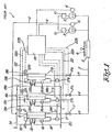
- Figure 1 shows a conventional cool drying installation 1 for cool drying gases that comprises a cooling circuit with a coolant in it, which can be driven around the circuit by one or more compressors connected in parallel by a drive by means of a motor 4 or similar.
- the flow direction of the coolant in the cooling circuit 2 is indicated in the drawing by the arrows M.
- the cooling circuit successively comprises, in the flow direction of the coolant, a condenser 5 that connects to the outlet of the compressor(s) 3 and which is cooled, for example by means of a fan 6 or by means of water; controllable expansion valves 7, 7A, 7B, each with an evaporator 8, 8A, 8B connected to each of them.
- the evaporators 8, 8A, 8B are placed in parallel in the cooling circuit and their respective outputs are connected, via a joint collection pipe 9 and a liquid separator 10 for each compressor 3, to the input of the aforementioned compressor(s).
- the sides of the respective expansion valves 7, 7A, 7B, that are not connected to a respective evaporator 8, 8A, 8B, are connected together and connect to the outlet side of the condenser 5, or in other words to the side of the condenser through which, during the operation of the cooling circuit 2, the liquid coolant leaves the condenser 5.
- the heat exchangers 11, 11A, 11B consist of an evaporator/gas section (8/13, 8A/13A, 8B/13B) and a gas-gas section 12, 12A, 12B.
- evaporator/gas 8/13, 8A/13A, 8B/13B a gas-gas section 12, 12A, 12B.
- 8A, 8B form the primary section of heat exchangers through which the coolant flows
- 13, 13A, 13B form the secondary section through which the gas to be dried flows.
- the gas to be dried is supplied via a joint inlet pipe 14 and individual inlet pipes 15, 15A, 15B in the direction of the arrows L.
- the gas first flows through the gas/gas section 12, 12A, 12B and then through the secondary section 13, 13A, 13B, where it comes into thermal contact with the evaporator 8, 8A, 8B to be thereby cooled.
- the condensate hereby formed can be separated in a condensate separator 16, 16A, 16B.
- the temperature of the air flow in this condensate separator 16, 16A, 16B is measured by a temperature measurement point 17, 17A, 17B that is connected to a control unit 18.
- the cooled gas stripped of water is then heated up again in the gas/gas section 12, 12A, 12B of the heat exchangers 11, 11A, 11B and driven via individual outlet pipes 19, 19A, 19B to a joint outlet pipe 20.
- the aforementioned gas/gas section 12, 12A, 12B of the heat exchangers hereby forms a recovery heat exchanger in which warm gas to be dried is precooled by gas already cooled in the secondary section 13, 13A, 13B that has been stripped of free condensate and that is thus heated up again.
- each evaporator 8, 8A and 8B there is a pressure and temperature measurement point 21, 21A, 21B that is connected to the control unit 18. It is also possible that the pressure and temperature measurement is directly coupled to one mechanical expansion valve.
- the information from these measurement points 21, 21A, 21B is used by the control unit 18 or by the individual valve itself to adjust the position of the respective expansion valves 7, 7A, 7B such that the temperature of the coolant at the outlet of each evaporator 8, 8A, 8B is such that the coolant is superheated, so that there is certainly no further liquid phase.
- Superheating means that the coolant has a higher temperature than the temperature at which the vapour pressure of the coolant is equal to the pressure, thus the condensation temperature of the coolant.
- the level of superheating can be expressed as a superheating temperature that is equal to the actual temperature of the coolant less the condensation temperature of the coolant.
- This superheating temperature has a certain target value, for example 5°C, that is chosen such that incomplete evaporation of liquid coolant is avoided, and also that an unnecessarily high superheating temperature with a possible negative impact on the lifetime of the components of the compressor(s) 3 and their energy efficiency is avoided.
- the condensation temperature is indirectly measured by a pressure measurement.
- the condensation temperature at a known pressure can then be calculated or read off from a table, such that from a measurement of pressure and temperature the superheating temperature can be calculated and the position of the expansion valves 7, 7A, 7B controlled on the basis of the difference between the calculated value and the target value of the superheating temperature.
- the dew point in the joint outlet pipe 20 of the gas to be dried corresponds to the average LAT, as measured by the temperature measurement points 17, 17A, 17B.
- This LAT is compared to a target value on the basis of which the speed of the drive motor(s) 4 of the compressor(s) is adjusted if necessary. In this way the capacity of the cooling circuit 2 can be adapted to the required cooling capacity.
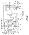
- a cool drying installation 1 that is equipped with a cooling circuit 2 according to the invention is shown in figure 2 .
- the realisation at the basis of this invention is not that the avoidance of the presence of liquid coolant in the individual evaporator 8, 8A, 8B is critical, but the avoidance of the presence of liquid coolant at the inlet of the compressor(s) 3, and this with the focus on an equal LAT in each of the heat exchangers 11, 11A, 11B.
- the coolant in an individual evaporator 8, 8A, 8B may be entirely or partially liquid for as long as the mixture is not totally superheated.
- the cool drying installation 1 with cooling circuit 2 according to the invention in contrast to the known cool drying installation 1, is not necessarily equipped with a pressure and temperature measurement point 21, 21A, 21B at the outlet of each evaporator 8, 8A, 8B.
- the collection pipe must be long enough to ensure good mixing of the coolant that comes out of the different evaporators 8, 8A, 8B and/or can be provided with means to improve the mixing, such as a static or otherwise mixer. If the mixing is very intensive, the collection pipe 9 can also be very short, and in extremis can even be limited to just a collection point where the coolant flows coming out of the evaporators 8, 8A, 8B come together.
- a cool drying installation 1 with cooling circuit 2 is the same as the traditional installation with regard to circulation, compression, expansion, cooling and heating of the coolant.
- the way in which the operation of the cooling circuit 2 is controlled is different and as described below.
- control unit 18 receives the LAT of each of the separate heat exchangers 11, 11A, 11B and the pressure and temperature values in the collection pipe 9 at the inlet of the compressors 3, from which the superheating temperature is calculated.
- the average opening of the expansion valves 7, 7A, 7B is adjusted to control the superheating temperature according to its target value, and this independently of the control of the individual expansion valves 7, 7A, 7B on the basis of other input data.
- the average LAT is also calculated. On the basis of this calculated average LAT and the individual LAT values of the respective heat exchangers 11, 11A, 11B the position of the expansion valve 7, 7A, 7B belonging to each heat exchanger 11, 11A, 11B is adjusted, and such that if the individual LAT is higher than the calculated average LAT, the expansion valve 7, 7A, 7B concerned opens to a lesser extent and vice versa. In this way the separate expansion valves 7, 7A, 7B are continuously controlled with the aim that the individual LAT values are controlled according to the average LAT value.
- the speed of the motor(s) 4 can be adjusted on the basis of the average LAT, just as with a traditional installation 1.
- the optimum control frequency for both the average position of the expansion valves 7, 7A, 7B for the superheating on the one hand, and the individual position for the LAT on the other, can also be determined by a person skilled in the art from the response characteristics of an individual cool drying installation 1.
- V n is the extent to which the opening or closing of the expansion valve 7, 7A, 7B with a number n has to be changed, as a result of a difference x n between the individual LAT in the respective secondary section 13, 13A, 13B with number n on the one hand, and the average LAT on the other defined as LAT n - LAT average .
- ABS(x n ) stands for the absolute value of x n .
- the invention is not limited to this specific function, but other functions are also possible.
- W is the extent to which the opening or closing of all expansion valves 7, 7A, 7B has to be changed as a result of the difference y between the superheating temperature and its target value.
- the invention is not limited to this specific function, but other functions are also possible.
- the parameters A, B, C, D, E, F, G, H are adjustable to obtain a good control characteristic, and depend on the control frequency among others.
- a total control in which the sum of the adjustments V n and W for each expansion valve 7, 7A, 7B is calculated and passed on at a certain frequency is also possible, instead of two separate adjustments V n and W.
- cooling circuit 2 is not limited to the cool drying of gases, but it can also be utilised for other applications.
- the cooling circuit 2 shown in figure 2 has three parallel evaporators 8, 8A, 8B, each with its own expansion valve 7, 7A, 7B. It is clear that this is only given as an example, and that the number of evaporator-expansion valve combinations 7-8 can be expanded according to desire. The invention even provides a relatively greater advantage with a larger number of parallel evaporators 8, 8A, 8B.
- the cooling circuit 2 shown in figure 2 has two parallel compressors 3. Such a cooling circuit 2 can also be constructed with different numbers of compressors 3, such as one, three or more.
- each heat exchanger 11, 11A, 11B is equipped with a primary section and a secondary section, but a cooling circuit according to the invention can also be used for other purposes than cool drying, in which case the presence of a secondary section of the heat exchangers 11, 11A, 11B is not always necessary.
- the invention is thus not limited in this way.
- the present invention is by no means limited to the embodiments described as an example and shown in the drawings, but a cooling circuit according to the invention and a method for controlling a cooling circuit can be realised in all kinds of variants, without departing from the scope of the invention.
Landscapes
- Engineering & Computer Science (AREA)
- Physics & Mathematics (AREA)
- Thermal Sciences (AREA)
- Mechanical Engineering (AREA)
- General Engineering & Computer Science (AREA)
- Chemical & Material Sciences (AREA)
- Analytical Chemistry (AREA)
- General Chemical & Material Sciences (AREA)
- Oil, Petroleum & Natural Gas (AREA)
- Chemical Kinetics & Catalysis (AREA)
- Drying Of Solid Materials (AREA)
- Drying Of Gases (AREA)
- Control Of Temperature (AREA)
Applications Claiming Priority (2)
| Application Number | Priority Date | Filing Date | Title |
|---|---|---|---|
| BE2012/0528A BE1021071B1 (nl) | 2012-08-03 | 2012-08-03 | Koelcircuit, koeldrooginstallatie en werkwijze voor het regelen van een koelcircuit |
| PCT/BE2013/000039 WO2014019033A1 (en) | 2012-08-03 | 2013-07-22 | Cooling circuit, dry cooling installation and method for controlling the cooling circuit |
Publications (2)
| Publication Number | Publication Date |
|---|---|
| EP2880376A1 EP2880376A1 (en) | 2015-06-10 |
| EP2880376B1 true EP2880376B1 (en) | 2016-11-02 |
Family
ID=46924164
Family Applications (1)
| Application Number | Title | Priority Date | Filing Date |
|---|---|---|---|
| EP13745563.0A Active EP2880376B1 (en) | 2012-08-03 | 2013-07-22 | Cooling circuit, dry cooling installation and method for controlling the cooling circuit |
Country Status (16)
| Country | Link |
|---|---|
| US (2) | US9915455B2 (ko) |
| EP (1) | EP2880376B1 (ko) |
| JP (1) | JP6307076B2 (ko) |
| KR (2) | KR20150040961A (ko) |
| CN (1) | CN104541114B (ko) |
| AU (1) | AU2013299340B2 (ko) |
| BE (1) | BE1021071B1 (ko) |
| BR (1) | BR112015002172B1 (ko) |
| CA (1) | CA2878974C (ko) |
| DK (1) | DK2880376T3 (ko) |
| ES (1) | ES2609986T3 (ko) |
| NZ (1) | NZ705261A (ko) |
| PL (1) | PL2880376T3 (ko) |
| PT (1) | PT2880376T (ko) |
| RU (1) | RU2599218C2 (ko) |
| WO (1) | WO2014019033A1 (ko) |
Families Citing this family (12)
| Publication number | Priority date | Publication date | Assignee | Title |
|---|---|---|---|---|
| BE1019199A3 (nl) * | 2010-02-24 | 2012-04-03 | Atlas Copco Airpower Nv | Werkwijze en inrichting voor het koeldrogen van gas. |
| BE1021838B1 (nl) * | 2014-05-09 | 2016-01-21 | Atlas Copco Airpower, Naamloze Vennootschap | Werkwijze en inrichting voor het koeldrogen van een gas |
| FR3024219B1 (fr) * | 2014-07-23 | 2016-07-15 | Air Liquide | Procede de regulation d'une installation de refrigeration cryogenique et installation correspondante |
| JP6007965B2 (ja) * | 2014-12-15 | 2016-10-19 | ダイキン工業株式会社 | 空気調和装置 |
| CN105302180B (zh) * | 2015-11-26 | 2018-09-21 | 重庆耐德工业股份有限公司 | 一种温度控制方法、系统和解吸塔 |
| US20170174049A1 (en) * | 2015-12-21 | 2017-06-22 | Ford Global Technologies, Llc | Dynamically controlled vapor compression cooling system with centrifugal compressor |
| EP3619480B1 (en) * | 2017-05-01 | 2023-10-25 | Danfoss A/S | A method for controlling suction pressure based on a most loaded cooling entity |
| CN107152810A (zh) * | 2017-06-27 | 2017-09-12 | 珠海格力电器股份有限公司 | 压缩机并联机组及具有其的空调系统 |
| KR101958345B1 (ko) * | 2017-09-22 | 2019-07-04 | (주) 지엔씨에너지 | 패키지형 바이오가스 수분 제거장치 |
| US11585608B2 (en) | 2018-02-05 | 2023-02-21 | Emerson Climate Technologies, Inc. | Climate-control system having thermal storage tank |
| US11149971B2 (en) | 2018-02-23 | 2021-10-19 | Emerson Climate Technologies, Inc. | Climate-control system with thermal storage device |
| US11346583B2 (en) * | 2018-06-27 | 2022-05-31 | Emerson Climate Technologies, Inc. | Climate-control system having vapor-injection compressors |
Family Cites Families (16)
| Publication number | Priority date | Publication date | Assignee | Title |
|---|---|---|---|---|
| JPH0694956B2 (ja) * | 1987-11-11 | 1994-11-24 | 三菱電機株式会社 | 多室形空気調和装置 |
| JP3056554B2 (ja) * | 1991-09-18 | 2000-06-26 | 松下精工株式会社 | 空気調和機 |
| JPH07120091A (ja) * | 1993-10-26 | 1995-05-12 | Toshiba Ave Corp | 空気調和機 |
| RU2272970C2 (ru) * | 2000-11-03 | 2006-03-27 | Синвент Ас | Обратимая система сжатия пара и обратимый теплообменник для текучего хладагента |
| US7086242B2 (en) * | 2001-07-13 | 2006-08-08 | Ebara Corporation | Dehumidifying air-conditioning apparatus |
| JP2002106925A (ja) * | 2001-08-24 | 2002-04-10 | Toshiba Kyaria Kk | 空気調和機 |
| US6715304B1 (en) * | 2002-12-05 | 2004-04-06 | Lyman W. Wycoff | Universal refrigerant controller |
| NL1026728C2 (nl) * | 2004-07-26 | 2006-01-31 | Antonie Bonte | Verbetering van koelsystemen. |
| DE602006011729D1 (ko) * | 2005-03-18 | 2010-03-04 | Danfoss As | |
| WO2008057647A2 (en) * | 2006-11-07 | 2008-05-15 | Tiax Llc. | Dehumidification |
| BE1017362A3 (nl) * | 2006-11-10 | 2008-07-01 | Atlas Copco Airpower Nv | Werkwijze voor het koeldrogen. |
| US8020391B2 (en) * | 2007-11-28 | 2011-09-20 | Hill Phoenix, Inc. | Refrigeration device control system |
| JP2013231519A (ja) * | 2010-08-31 | 2013-11-14 | Sanyo Electric Co Ltd | 冷却システム制御装置 |
| JP2012245501A (ja) * | 2011-05-31 | 2012-12-13 | Orion Machinery Co Ltd | 圧縮空気除湿装置 |
| JP2013002749A (ja) * | 2011-06-17 | 2013-01-07 | Hitachi Appliances Inc | 空気調和装置 |
| JP6094956B2 (ja) | 2012-09-26 | 2017-03-15 | パナソニックIpマネジメント株式会社 | 画像符号化装置、撮影画像記録システム、撮像装置、画像符号化方法、および画像符号化プログラム |
-
2012
- 2012-08-03 BE BE2012/0528A patent/BE1021071B1/nl active
-
2013
- 2013-07-22 DK DK13745563.0T patent/DK2880376T3/en active
- 2013-07-22 KR KR20157004973A patent/KR20150040961A/ko active Application Filing
- 2013-07-22 JP JP2015524575A patent/JP6307076B2/ja active Active
- 2013-07-22 AU AU2013299340A patent/AU2013299340B2/en active Active
- 2013-07-22 US US14/418,245 patent/US9915455B2/en active Active
- 2013-07-22 BR BR112015002172-7A patent/BR112015002172B1/pt active IP Right Grant
- 2013-07-22 EP EP13745563.0A patent/EP2880376B1/en active Active
- 2013-07-22 PT PT137455630T patent/PT2880376T/pt unknown
- 2013-07-22 RU RU2015107191/06A patent/RU2599218C2/ru active
- 2013-07-22 KR KR1020177007273A patent/KR101849890B1/ko active IP Right Grant
- 2013-07-22 WO PCT/BE2013/000039 patent/WO2014019033A1/en active Application Filing
- 2013-07-22 PL PL13745563T patent/PL2880376T3/pl unknown
- 2013-07-22 CN CN201380041178.4A patent/CN104541114B/zh active Active
- 2013-07-22 CA CA2878974A patent/CA2878974C/en active Active
- 2013-07-22 NZ NZ705261A patent/NZ705261A/en unknown
- 2013-07-22 ES ES13745563.0T patent/ES2609986T3/es active Active
-
2017
- 2017-12-18 US US15/844,841 patent/US10060663B2/en active Active
Also Published As
| Publication number | Publication date |
|---|---|
| AU2013299340B2 (en) | 2017-09-14 |
| US9915455B2 (en) | 2018-03-13 |
| US20180106517A1 (en) | 2018-04-19 |
| DK2880376T3 (en) | 2017-02-06 |
| RU2599218C2 (ru) | 2016-10-10 |
| CA2878974C (en) | 2017-09-12 |
| BR112015002172B1 (pt) | 2021-09-28 |
| NZ705261A (en) | 2016-10-28 |
| KR20170033907A (ko) | 2017-03-27 |
| US10060663B2 (en) | 2018-08-28 |
| KR101849890B1 (ko) | 2018-05-31 |
| KR20150040961A (ko) | 2015-04-15 |
| CN104541114A (zh) | 2015-04-22 |
| ES2609986T3 (es) | 2017-04-25 |
| US20150168038A1 (en) | 2015-06-18 |
| RU2015107191A (ru) | 2016-09-27 |
| BE1021071B1 (nl) | 2015-04-21 |
| JP6307076B2 (ja) | 2018-04-04 |
| CA2878974A1 (en) | 2014-02-06 |
| PL2880376T3 (pl) | 2017-09-29 |
| JP2015523539A (ja) | 2015-08-13 |
| CN104541114B (zh) | 2016-08-24 |
| BR112015002172A2 (pt) | 2017-07-04 |
| WO2014019033A1 (en) | 2014-02-06 |
| PT2880376T (pt) | 2016-12-22 |
| EP2880376A1 (en) | 2015-06-10 |
| AU2013299340A1 (en) | 2015-02-19 |
Similar Documents
| Publication | Publication Date | Title |
|---|---|---|
| EP2880376B1 (en) | Cooling circuit, dry cooling installation and method for controlling the cooling circuit | |
| EP3203165B1 (en) | Air conditioner | |
| EP2270405B1 (en) | Refrigerating device | |
| US7984621B2 (en) | Air conditioning system for communication equipment and controlling method thereof | |
| EP2881684B1 (en) | Container refrigeration device | |
| US10920760B2 (en) | Air compressor having an oil separator, an oil cooler, first and second evaporators, and wherein intake air and the oil are simultaneously cooled in the first and second evaporators | |
| EP3607252B1 (en) | Chiller system with an economizer module and method of operating such a system | |
| JP6091614B2 (ja) | ヒートポンプ装置 | |
| EP2881685B1 (en) | Container refrigeration device and control method thereof | |
| JP2010104964A (ja) | 冷凍式エアドライヤ | |
| US20120286060A1 (en) | Device for making artificial snow | |
| WO2007102345A1 (ja) | 冷凍装置 | |
| EP2165135B1 (en) | Refrigerating system | |
| EP3140023B1 (en) | Method and device for cool-drying a gas using a heat exchanger with closed cooling circuit | |
| JP2019052817A (ja) | 空気調和装置 | |
| KR20150114232A (ko) | 저노점 냉풍건조기 | |
| WO2015131184A1 (en) | Freeze inhibiting regrigeration circuit and method of operation | |
| KR970062607A (ko) | 공기 조화용 열 펌프 장치 | |
| US20060242974A1 (en) | Evaporation process control for use in refrigeration technology | |
| US20240044530A1 (en) | Test chamber and method for its control | |
| JPS62194146A (ja) | 空気調和機 | |
| US20110154849A1 (en) | Symmetric refrigerant regulator for flooded multichannel evaporator | |
| JP5578884B2 (ja) | 高顕熱形ガスヒートポンプ空気調和機 | |
| KR20110076559A (ko) | 히트펌프식 냉난방장치 |
Legal Events
| Date | Code | Title | Description |
|---|---|---|---|
| PUAI | Public reference made under article 153(3) epc to a published international application that has entered the european phase |
Free format text: ORIGINAL CODE: 0009012 |
|
| 17P | Request for examination filed |
Effective date: 20150109 |
|
| AK | Designated contracting states |
Kind code of ref document: A1 Designated state(s): AL AT BE BG CH CY CZ DE DK EE ES FI FR GB GR HR HU IE IS IT LI LT LU LV MC MK MT NL NO PL PT RO RS SE SI SK SM TR |
|
| AX | Request for extension of the european patent |
Extension state: BA ME |
|
| DAX | Request for extension of the european patent (deleted) | ||
| GRAP | Despatch of communication of intention to grant a patent |
Free format text: ORIGINAL CODE: EPIDOSNIGR1 |
|
| INTG | Intention to grant announced |
Effective date: 20160630 |
|
| GRAS | Grant fee paid |
Free format text: ORIGINAL CODE: EPIDOSNIGR3 |
|
| GRAA | (expected) grant |
Free format text: ORIGINAL CODE: 0009210 |
|
| AK | Designated contracting states |
Kind code of ref document: B1 Designated state(s): AL AT BE BG CH CY CZ DE DK EE ES FI FR GB GR HR HU IE IS IT LI LT LU LV MC MK MT NL NO PL PT RO RS SE SI SK SM TR |
|
| REG | Reference to a national code |
Ref country code: GB Ref legal event code: FG4D |
|
| REG | Reference to a national code |
Ref country code: AT Ref legal event code: REF Ref document number: 842256 Country of ref document: AT Kind code of ref document: T Effective date: 20161115 Ref country code: CH Ref legal event code: EP |
|
| REG | Reference to a national code |
Ref country code: IE Ref legal event code: FG4D |
|
| REG | Reference to a national code |
Ref country code: CH Ref legal event code: NV Representative=s name: ORITI PATENTS FRANCO ORITI, CH Ref country code: DE Ref legal event code: R096 Ref document number: 602013013527 Country of ref document: DE |
|
| REG | Reference to a national code |
Ref country code: PT Ref legal event code: SC4A Ref document number: 2880376 Country of ref document: PT Date of ref document: 20161222 Kind code of ref document: T Free format text: AVAILABILITY OF NATIONAL TRANSLATION Effective date: 20161213 |
|
| REG | Reference to a national code |
Ref country code: SE Ref legal event code: TRGR |
|
| REG | Reference to a national code |
Ref country code: DK Ref legal event code: T3 Effective date: 20170130 |
|
| REG | Reference to a national code |
Ref country code: NL Ref legal event code: FP |
|
| PG25 | Lapsed in a contracting state [announced via postgrant information from national office to epo] |
Ref country code: LV Free format text: LAPSE BECAUSE OF FAILURE TO SUBMIT A TRANSLATION OF THE DESCRIPTION OR TO PAY THE FEE WITHIN THE PRESCRIBED TIME-LIMIT Effective date: 20161102 |
|
| REG | Reference to a national code |
Ref country code: LT Ref legal event code: MG4D |
|
| REG | Reference to a national code |
Ref country code: NO Ref legal event code: T2 Effective date: 20161102 |
|
| REG | Reference to a national code |
Ref country code: ES Ref legal event code: FG2A Ref document number: 2609986 Country of ref document: ES Kind code of ref document: T3 Effective date: 20170425 |
|
| PG25 | Lapsed in a contracting state [announced via postgrant information from national office to epo] |
Ref country code: LT Free format text: LAPSE BECAUSE OF FAILURE TO SUBMIT A TRANSLATION OF THE DESCRIPTION OR TO PAY THE FEE WITHIN THE PRESCRIBED TIME-LIMIT Effective date: 20161102 Ref country code: GR Free format text: LAPSE BECAUSE OF FAILURE TO SUBMIT A TRANSLATION OF THE DESCRIPTION OR TO PAY THE FEE WITHIN THE PRESCRIBED TIME-LIMIT Effective date: 20170203 |
|
| PG25 | Lapsed in a contracting state [announced via postgrant information from national office to epo] |
Ref country code: RS Free format text: LAPSE BECAUSE OF FAILURE TO SUBMIT A TRANSLATION OF THE DESCRIPTION OR TO PAY THE FEE WITHIN THE PRESCRIBED TIME-LIMIT Effective date: 20161102 Ref country code: IS Free format text: LAPSE BECAUSE OF FAILURE TO SUBMIT A TRANSLATION OF THE DESCRIPTION OR TO PAY THE FEE WITHIN THE PRESCRIBED TIME-LIMIT Effective date: 20170302 Ref country code: FI Free format text: LAPSE BECAUSE OF FAILURE TO SUBMIT A TRANSLATION OF THE DESCRIPTION OR TO PAY THE FEE WITHIN THE PRESCRIBED TIME-LIMIT Effective date: 20161102 Ref country code: HR Free format text: LAPSE BECAUSE OF FAILURE TO SUBMIT A TRANSLATION OF THE DESCRIPTION OR TO PAY THE FEE WITHIN THE PRESCRIBED TIME-LIMIT Effective date: 20161102 |
|
| REG | Reference to a national code |
Ref country code: FR Ref legal event code: PLFP Year of fee payment: 5 |
|
| PG25 | Lapsed in a contracting state [announced via postgrant information from national office to epo] |
Ref country code: EE Free format text: LAPSE BECAUSE OF FAILURE TO SUBMIT A TRANSLATION OF THE DESCRIPTION OR TO PAY THE FEE WITHIN THE PRESCRIBED TIME-LIMIT Effective date: 20161102 Ref country code: SK Free format text: LAPSE BECAUSE OF FAILURE TO SUBMIT A TRANSLATION OF THE DESCRIPTION OR TO PAY THE FEE WITHIN THE PRESCRIBED TIME-LIMIT Effective date: 20161102 Ref country code: RO Free format text: LAPSE BECAUSE OF FAILURE TO SUBMIT A TRANSLATION OF THE DESCRIPTION OR TO PAY THE FEE WITHIN THE PRESCRIBED TIME-LIMIT Effective date: 20161102 |
|
| REG | Reference to a national code |
Ref country code: DE Ref legal event code: R097 Ref document number: 602013013527 Country of ref document: DE |
|
| PG25 | Lapsed in a contracting state [announced via postgrant information from national office to epo] |
Ref country code: BG Free format text: LAPSE BECAUSE OF FAILURE TO SUBMIT A TRANSLATION OF THE DESCRIPTION OR TO PAY THE FEE WITHIN THE PRESCRIBED TIME-LIMIT Effective date: 20170202 Ref country code: SM Free format text: LAPSE BECAUSE OF FAILURE TO SUBMIT A TRANSLATION OF THE DESCRIPTION OR TO PAY THE FEE WITHIN THE PRESCRIBED TIME-LIMIT Effective date: 20161102 |
|
| PLBE | No opposition filed within time limit |
Free format text: ORIGINAL CODE: 0009261 |
|
| STAA | Information on the status of an ep patent application or granted ep patent |
Free format text: STATUS: NO OPPOSITION FILED WITHIN TIME LIMIT |
|
| 26N | No opposition filed |
Effective date: 20170803 |
|
| PG25 | Lapsed in a contracting state [announced via postgrant information from national office to epo] |
Ref country code: SI Free format text: LAPSE BECAUSE OF FAILURE TO SUBMIT A TRANSLATION OF THE DESCRIPTION OR TO PAY THE FEE WITHIN THE PRESCRIBED TIME-LIMIT Effective date: 20161102 |
|
| REG | Reference to a national code |
Ref country code: IE Ref legal event code: MM4A |
|
| PG25 | Lapsed in a contracting state [announced via postgrant information from national office to epo] |
Ref country code: IE Free format text: LAPSE BECAUSE OF NON-PAYMENT OF DUE FEES Effective date: 20170722 |
|
| REG | Reference to a national code |
Ref country code: FR Ref legal event code: PLFP Year of fee payment: 6 |
|
| PG25 | Lapsed in a contracting state [announced via postgrant information from national office to epo] |
Ref country code: MT Free format text: LAPSE BECAUSE OF NON-PAYMENT OF DUE FEES Effective date: 20170722 |
|
| PG25 | Lapsed in a contracting state [announced via postgrant information from national office to epo] |
Ref country code: HU Free format text: LAPSE BECAUSE OF FAILURE TO SUBMIT A TRANSLATION OF THE DESCRIPTION OR TO PAY THE FEE WITHIN THE PRESCRIBED TIME-LIMIT; INVALID AB INITIO Effective date: 20130722 Ref country code: MC Free format text: LAPSE BECAUSE OF FAILURE TO SUBMIT A TRANSLATION OF THE DESCRIPTION OR TO PAY THE FEE WITHIN THE PRESCRIBED TIME-LIMIT Effective date: 20161102 |
|
| PG25 | Lapsed in a contracting state [announced via postgrant information from national office to epo] |
Ref country code: CY Free format text: LAPSE BECAUSE OF FAILURE TO SUBMIT A TRANSLATION OF THE DESCRIPTION OR TO PAY THE FEE WITHIN THE PRESCRIBED TIME-LIMIT Effective date: 20161102 |
|
| PG25 | Lapsed in a contracting state [announced via postgrant information from national office to epo] |
Ref country code: MK Free format text: LAPSE BECAUSE OF FAILURE TO SUBMIT A TRANSLATION OF THE DESCRIPTION OR TO PAY THE FEE WITHIN THE PRESCRIBED TIME-LIMIT Effective date: 20161102 |
|
| PG25 | Lapsed in a contracting state [announced via postgrant information from national office to epo] |
Ref country code: AL Free format text: LAPSE BECAUSE OF FAILURE TO SUBMIT A TRANSLATION OF THE DESCRIPTION OR TO PAY THE FEE WITHIN THE PRESCRIBED TIME-LIMIT Effective date: 20161102 |
|
| P01 | Opt-out of the competence of the unified patent court (upc) registered |
Effective date: 20230602 |
|
| PGFP | Annual fee paid to national office [announced via postgrant information from national office to epo] |
Ref country code: TR Payment date: 20230707 Year of fee payment: 11 Ref country code: NO Payment date: 20230727 Year of fee payment: 11 Ref country code: IT Payment date: 20230720 Year of fee payment: 11 Ref country code: GB Payment date: 20230727 Year of fee payment: 11 Ref country code: ES Payment date: 20230804 Year of fee payment: 11 Ref country code: CZ Payment date: 20230711 Year of fee payment: 11 Ref country code: CH Payment date: 20230802 Year of fee payment: 11 Ref country code: AT Payment date: 20230705 Year of fee payment: 11 |
|
| PGFP | Annual fee paid to national office [announced via postgrant information from national office to epo] |
Ref country code: SE Payment date: 20230727 Year of fee payment: 11 Ref country code: PT Payment date: 20230704 Year of fee payment: 11 Ref country code: PL Payment date: 20230705 Year of fee payment: 11 Ref country code: FR Payment date: 20230725 Year of fee payment: 11 Ref country code: DK Payment date: 20230727 Year of fee payment: 11 Ref country code: DE Payment date: 20230727 Year of fee payment: 11 Ref country code: BE Payment date: 20230727 Year of fee payment: 11 |
|
| PGFP | Annual fee paid to national office [announced via postgrant information from national office to epo] |
Ref country code: LU Payment date: 20240729 Year of fee payment: 12 |
|
| PGFP | Annual fee paid to national office [announced via postgrant information from national office to epo] |
Ref country code: NL Payment date: 20240726 Year of fee payment: 12 |