EP2879737B1 - Auto-injecteur - Google Patents
Auto-injecteur Download PDFInfo
- Publication number
- EP2879737B1 EP2879737B1 EP13741801.8A EP13741801A EP2879737B1 EP 2879737 B1 EP2879737 B1 EP 2879737B1 EP 13741801 A EP13741801 A EP 13741801A EP 2879737 B1 EP2879737 B1 EP 2879737B1
- Authority
- EP
- European Patent Office
- Prior art keywords
- cassette unit
- drive
- plunger
- syringe
- cassette
- Prior art date
- Legal status (The legal status is an assumption and is not a legal conclusion. Google has not performed a legal analysis and makes no representation as to the accuracy of the status listed.)
- Active
Links
- 229940090047 auto-injector Drugs 0.000 title claims description 24
- 239000007788 liquid Substances 0.000 claims description 38
- 239000013583 drug formulation Substances 0.000 claims description 36
- 238000003032 molecular docking Methods 0.000 claims description 28
- 239000003814 drug Substances 0.000 claims description 27
- 229940079593 drug Drugs 0.000 claims description 26
- 238000012546 transfer Methods 0.000 claims description 25
- 238000012384 transportation and delivery Methods 0.000 claims description 18
- 230000004044 response Effects 0.000 claims description 15
- 230000002093 peripheral effect Effects 0.000 claims description 5
- 239000013011 aqueous formulation Substances 0.000 claims description 2
- 230000001225 therapeutic effect Effects 0.000 claims description 2
- 238000002347 injection Methods 0.000 description 31
- 239000007924 injection Substances 0.000 description 31
- 230000009471 action Effects 0.000 description 19
- 230000006870 function Effects 0.000 description 18
- 230000003993 interaction Effects 0.000 description 18
- 239000000463 material Substances 0.000 description 15
- 230000000903 blocking effect Effects 0.000 description 14
- 210000003811 finger Anatomy 0.000 description 11
- 238000000034 method Methods 0.000 description 9
- 238000012795 verification Methods 0.000 description 9
- 230000000007 visual effect Effects 0.000 description 9
- 238000003780 insertion Methods 0.000 description 5
- 230000037431 insertion Effects 0.000 description 5
- 230000007246 mechanism Effects 0.000 description 5
- 102000015636 Oligopeptides Human genes 0.000 description 4
- 108010038807 Oligopeptides Proteins 0.000 description 4
- -1 polyethylene Polymers 0.000 description 4
- 229920001184 polypeptide Polymers 0.000 description 4
- 102000004196 processed proteins & peptides Human genes 0.000 description 4
- 108090000765 processed proteins & peptides Proteins 0.000 description 4
- 239000000243 solution Substances 0.000 description 4
- 238000011282 treatment Methods 0.000 description 4
- 108060003951 Immunoglobulin Proteins 0.000 description 3
- 102000015696 Interleukins Human genes 0.000 description 3
- 108010063738 Interleukins Proteins 0.000 description 3
- 206010055082 Lip injury Diseases 0.000 description 3
- HEMHJVSKTPXQMS-UHFFFAOYSA-M Sodium hydroxide Chemical compound [OH-].[Na+] HEMHJVSKTPXQMS-UHFFFAOYSA-M 0.000 description 3
- 208000037265 diseases, disorders, signs and symptoms Diseases 0.000 description 3
- 238000012377 drug delivery Methods 0.000 description 3
- 229920001971 elastomer Polymers 0.000 description 3
- 239000012634 fragment Substances 0.000 description 3
- 239000011521 glass Substances 0.000 description 3
- 102000018358 immunoglobulin Human genes 0.000 description 3
- 102000004169 proteins and genes Human genes 0.000 description 3
- 108090000623 proteins and genes Proteins 0.000 description 3
- 239000005060 rubber Substances 0.000 description 3
- 238000007493 shaping process Methods 0.000 description 3
- 108010050904 Interferons Proteins 0.000 description 2
- 102000014150 Interferons Human genes 0.000 description 2
- 206010028980 Neoplasm Diseases 0.000 description 2
- FAPWRFPIFSIZLT-UHFFFAOYSA-M Sodium chloride Chemical compound [Na+].[Cl-] FAPWRFPIFSIZLT-UHFFFAOYSA-M 0.000 description 2
- 239000003795 chemical substances by application Substances 0.000 description 2
- 238000004891 communication Methods 0.000 description 2
- 230000001010 compromised effect Effects 0.000 description 2
- 201000010099 disease Diseases 0.000 description 2
- 230000000694 effects Effects 0.000 description 2
- 206010015037 epilepsy Diseases 0.000 description 2
- 150000004676 glycans Chemical class 0.000 description 2
- 229940088597 hormone Drugs 0.000 description 2
- 239000005556 hormone Substances 0.000 description 2
- 229940072221 immunoglobulins Drugs 0.000 description 2
- 208000015181 infectious disease Diseases 0.000 description 2
- 208000000509 infertility Diseases 0.000 description 2
- 230000036512 infertility Effects 0.000 description 2
- 231100000535 infertility Toxicity 0.000 description 2
- 208000027866 inflammatory disease Diseases 0.000 description 2
- NOESYZHRGYRDHS-UHFFFAOYSA-N insulin Chemical compound N1C(=O)C(NC(=O)C(CCC(N)=O)NC(=O)C(CCC(O)=O)NC(=O)C(C(C)C)NC(=O)C(NC(=O)CN)C(C)CC)CSSCC(C(NC(CO)C(=O)NC(CC(C)C)C(=O)NC(CC=2C=CC(O)=CC=2)C(=O)NC(CCC(N)=O)C(=O)NC(CC(C)C)C(=O)NC(CCC(O)=O)C(=O)NC(CC(N)=O)C(=O)NC(CC=2C=CC(O)=CC=2)C(=O)NC(CSSCC(NC(=O)C(C(C)C)NC(=O)C(CC(C)C)NC(=O)C(CC=2C=CC(O)=CC=2)NC(=O)C(CC(C)C)NC(=O)C(C)NC(=O)C(CCC(O)=O)NC(=O)C(C(C)C)NC(=O)C(CC(C)C)NC(=O)C(CC=2NC=NC=2)NC(=O)C(CO)NC(=O)CNC2=O)C(=O)NCC(=O)NC(CCC(O)=O)C(=O)NC(CCCNC(N)=N)C(=O)NCC(=O)NC(CC=3C=CC=CC=3)C(=O)NC(CC=3C=CC=CC=3)C(=O)NC(CC=3C=CC(O)=CC=3)C(=O)NC(C(C)O)C(=O)N3C(CCC3)C(=O)NC(CCCCN)C(=O)NC(C)C(O)=O)C(=O)NC(CC(N)=O)C(O)=O)=O)NC(=O)C(C(C)CC)NC(=O)C(CO)NC(=O)C(C(C)O)NC(=O)C1CSSCC2NC(=O)C(CC(C)C)NC(=O)C(NC(=O)C(CCC(N)=O)NC(=O)C(CC(N)=O)NC(=O)C(NC(=O)C(N)CC=1C=CC=CC=1)C(C)C)CC1=CN=CN1 NOESYZHRGYRDHS-UHFFFAOYSA-N 0.000 description 2
- 229940079322 interferon Drugs 0.000 description 2
- 229920001427 mPEG Polymers 0.000 description 2
- 239000002184 metal Substances 0.000 description 2
- 239000004033 plastic Substances 0.000 description 2
- 229920003023 plastic Polymers 0.000 description 2
- 229920001223 polyethylene glycol Polymers 0.000 description 2
- 229920000642 polymer Polymers 0.000 description 2
- 229920001282 polysaccharide Polymers 0.000 description 2
- 239000005017 polysaccharide Substances 0.000 description 2
- 238000003825 pressing Methods 0.000 description 2
- 230000000717 retained effect Effects 0.000 description 2
- 230000002441 reversible effect Effects 0.000 description 2
- 230000035939 shock Effects 0.000 description 2
- 229920001059 synthetic polymer Polymers 0.000 description 2
- 201000000596 systemic lupus erythematosus Diseases 0.000 description 2
- 210000003813 thumb Anatomy 0.000 description 2
- SFLSHLFXELFNJZ-QMMMGPOBSA-N (-)-norepinephrine Chemical compound NC[C@H](O)C1=CC=C(O)C(O)=C1 SFLSHLFXELFNJZ-QMMMGPOBSA-N 0.000 description 1
- UCTWMZQNUQWSLP-VIFPVBQESA-N (R)-adrenaline Chemical compound CNC[C@H](O)C1=CC=C(O)C(O)=C1 UCTWMZQNUQWSLP-VIFPVBQESA-N 0.000 description 1
- 229930182837 (R)-adrenaline Natural products 0.000 description 1
- QTBSBXVTEAMEQO-UHFFFAOYSA-M Acetate Chemical compound CC([O-])=O QTBSBXVTEAMEQO-UHFFFAOYSA-M 0.000 description 1
- 208000031261 Acute myeloid leukaemia Diseases 0.000 description 1
- 208000024827 Alzheimer disease Diseases 0.000 description 1
- 201000001320 Atherosclerosis Diseases 0.000 description 1
- 208000032791 BCR-ABL1 positive chronic myelogenous leukemia Diseases 0.000 description 1
- 208000020084 Bone disease Diseases 0.000 description 1
- 102000019034 Chemokines Human genes 0.000 description 1
- 108010012236 Chemokines Proteins 0.000 description 1
- 208000006545 Chronic Obstructive Pulmonary Disease Diseases 0.000 description 1
- 208000010833 Chronic myeloid leukaemia Diseases 0.000 description 1
- 206010009900 Colitis ulcerative Diseases 0.000 description 1
- 206010009944 Colon cancer Diseases 0.000 description 1
- 102000007644 Colony-Stimulating Factors Human genes 0.000 description 1
- 108010071942 Colony-Stimulating Factors Proteins 0.000 description 1
- 208000027205 Congenital disease Diseases 0.000 description 1
- 208000029767 Congenital, Hereditary, and Neonatal Diseases and Abnormalities Diseases 0.000 description 1
- 208000011231 Crohn disease Diseases 0.000 description 1
- 229920000089 Cyclic olefin copolymer Polymers 0.000 description 1
- 201000003883 Cystic fibrosis Diseases 0.000 description 1
- 102000004127 Cytokines Human genes 0.000 description 1
- 108090000695 Cytokines Proteins 0.000 description 1
- 206010014824 Endotoxic shock Diseases 0.000 description 1
- 102000004190 Enzymes Human genes 0.000 description 1
- 108090000790 Enzymes Proteins 0.000 description 1
- 102000003951 Erythropoietin Human genes 0.000 description 1
- 108090000394 Erythropoietin Proteins 0.000 description 1
- 102000003886 Glycoproteins Human genes 0.000 description 1
- 108090000288 Glycoproteins Proteins 0.000 description 1
- 208000009329 Graft vs Host Disease Diseases 0.000 description 1
- 108010051696 Growth Hormone Proteins 0.000 description 1
- 102000018997 Growth Hormone Human genes 0.000 description 1
- 208000031886 HIV Infections Diseases 0.000 description 1
- 208000037357 HIV infectious disease Diseases 0.000 description 1
- 208000002250 Hematologic Neoplasms Diseases 0.000 description 1
- 101000998146 Homo sapiens Interleukin-17A Proteins 0.000 description 1
- 102000001706 Immunoglobulin Fab Fragments Human genes 0.000 description 1
- 108010054477 Immunoglobulin Fab Fragments Proteins 0.000 description 1
- 102000008394 Immunoglobulin Fragments Human genes 0.000 description 1
- 108010021625 Immunoglobulin Fragments Proteins 0.000 description 1
- 102000004877 Insulin Human genes 0.000 description 1
- 108090001061 Insulin Proteins 0.000 description 1
- 102100026720 Interferon beta Human genes 0.000 description 1
- 102100037850 Interferon gamma Human genes 0.000 description 1
- 108090000467 Interferon-beta Proteins 0.000 description 1
- 108010074328 Interferon-gamma Proteins 0.000 description 1
- 102000003816 Interleukin-13 Human genes 0.000 description 1
- 108090000176 Interleukin-13 Proteins 0.000 description 1
- 102100033461 Interleukin-17A Human genes 0.000 description 1
- 108010002350 Interleukin-2 Proteins 0.000 description 1
- 102000000588 Interleukin-2 Human genes 0.000 description 1
- 108010002386 Interleukin-3 Proteins 0.000 description 1
- 102000000646 Interleukin-3 Human genes 0.000 description 1
- 102000004388 Interleukin-4 Human genes 0.000 description 1
- 108090000978 Interleukin-4 Proteins 0.000 description 1
- 108010002616 Interleukin-5 Proteins 0.000 description 1
- 102000000743 Interleukin-5 Human genes 0.000 description 1
- 102000004889 Interleukin-6 Human genes 0.000 description 1
- 108090001005 Interleukin-6 Proteins 0.000 description 1
- JVTAAEKCZFNVCJ-UHFFFAOYSA-M Lactate Chemical compound CC(O)C([O-])=O JVTAAEKCZFNVCJ-UHFFFAOYSA-M 0.000 description 1
- 108010074338 Lymphokines Proteins 0.000 description 1
- 102000008072 Lymphokines Human genes 0.000 description 1
- 208000029725 Metabolic bone disease Diseases 0.000 description 1
- 208000033761 Myelogenous Chronic BCR-ABL Positive Leukemia Diseases 0.000 description 1
- 108010025020 Nerve Growth Factor Proteins 0.000 description 1
- 102000015336 Nerve Growth Factor Human genes 0.000 description 1
- 206010049088 Osteopenia Diseases 0.000 description 1
- 208000001132 Osteoporosis Diseases 0.000 description 1
- 206010061535 Ovarian neoplasm Diseases 0.000 description 1
- 101800000989 Oxytocin Proteins 0.000 description 1
- 102400000050 Oxytocin Human genes 0.000 description 1
- XNOPRXBHLZRZKH-UHFFFAOYSA-N Oxytocin Natural products N1C(=O)C(N)CSSCC(C(=O)N2C(CCC2)C(=O)NC(CC(C)C)C(=O)NCC(N)=O)NC(=O)C(CC(N)=O)NC(=O)C(CCC(N)=O)NC(=O)C(C(C)CC)NC(=O)C1CC1=CC=C(O)C=C1 XNOPRXBHLZRZKH-UHFFFAOYSA-N 0.000 description 1
- 108010038512 Platelet-Derived Growth Factor Proteins 0.000 description 1
- 102000010780 Platelet-Derived Growth Factor Human genes 0.000 description 1
- 239000005062 Polybutadiene Substances 0.000 description 1
- 239000004698 Polyethylene Substances 0.000 description 1
- 239000004743 Polypropylene Substances 0.000 description 1
- 201000004681 Psoriasis Diseases 0.000 description 1
- 201000001263 Psoriatic Arthritis Diseases 0.000 description 1
- 208000036824 Psoriatic arthropathy Diseases 0.000 description 1
- 102000007056 Recombinant Fusion Proteins Human genes 0.000 description 1
- 108010008281 Recombinant Fusion Proteins Proteins 0.000 description 1
- 206010039491 Sarcoma Diseases 0.000 description 1
- 206010040070 Septic Shock Diseases 0.000 description 1
- 208000005718 Stomach Neoplasms Diseases 0.000 description 1
- 102000003978 Tissue Plasminogen Activator Human genes 0.000 description 1
- 108090000373 Tissue Plasminogen Activator Proteins 0.000 description 1
- 206010052779 Transplant rejections Diseases 0.000 description 1
- 102000009270 Tumour necrosis factor alpha Human genes 0.000 description 1
- 108050000101 Tumour necrosis factor alpha Proteins 0.000 description 1
- 201000006704 Ulcerative Colitis Diseases 0.000 description 1
- 230000004913 activation Effects 0.000 description 1
- 239000013543 active substance Substances 0.000 description 1
- 238000007792 addition Methods 0.000 description 1
- 230000002730 additional effect Effects 0.000 description 1
- 206010003246 arthritis Diseases 0.000 description 1
- 208000006673 asthma Diseases 0.000 description 1
- 230000005784 autoimmunity Effects 0.000 description 1
- 230000001580 bacterial effect Effects 0.000 description 1
- MSYKRHVOOPPJKU-BDAKNGLRSA-N brivaracetam Chemical compound CCC[C@H]1CN([C@@H](CC)C(N)=O)C(=O)C1 MSYKRHVOOPPJKU-BDAKNGLRSA-N 0.000 description 1
- 229960002161 brivaracetam Drugs 0.000 description 1
- 239000000872 buffer Substances 0.000 description 1
- 201000011510 cancer Diseases 0.000 description 1
- 210000003169 central nervous system Anatomy 0.000 description 1
- 150000005829 chemical entities Chemical class 0.000 description 1
- 230000015271 coagulation Effects 0.000 description 1
- 238000005345 coagulation Methods 0.000 description 1
- 208000029742 colonic neoplasm Diseases 0.000 description 1
- 230000001276 controlling effect Effects 0.000 description 1
- 229960000258 corticotropin Drugs 0.000 description 1
- IDLFZVILOHSSID-OVLDLUHVSA-N corticotropin Chemical compound C([C@@H](C(=O)N[C@@H](CO)C(=O)N[C@@H](CCSC)C(=O)N[C@@H](CCC(O)=O)C(=O)N[C@@H](CC=1NC=NC=1)C(=O)N[C@@H](CC=1C=CC=CC=1)C(=O)N[C@@H](CCCNC(N)=N)C(=O)N[C@@H](CC=1C2=CC=CC=C2NC=1)C(=O)NCC(=O)N[C@@H](CCCCN)C(=O)N1[C@@H](CCC1)C(=O)N[C@@H](C(C)C)C(=O)NCC(=O)N[C@@H](CCCCN)C(=O)N[C@@H](CCCCN)C(=O)N[C@@H](CCCNC(N)=N)C(=O)N[C@@H](CCCNC(N)=N)C(=O)N1[C@@H](CCC1)C(=O)N[C@@H](C(C)C)C(=O)N[C@@H](CCCCN)C(=O)N[C@@H](C(C)C)C(=O)N[C@@H](CC=1C=CC(O)=CC=1)C(=O)N1[C@@H](CCC1)C(=O)N[C@@H](CC(N)=O)C(=O)NCC(=O)N[C@@H](C)C(=O)N[C@@H](CCC(O)=O)C(=O)N[C@@H](CC(O)=O)C(=O)N[C@@H](CCC(O)=O)C(=O)N[C@@H](CO)C(=O)N[C@@H](C)C(=O)N[C@@H](CCC(O)=O)C(=O)N[C@@H](C)C(=O)N[C@@H](CC=1C=CC=CC=1)C(=O)N1[C@@H](CCC1)C(=O)N[C@@H](CC(C)C)C(=O)N[C@@H](CCC(O)=O)C(=O)N[C@@H](CC=1C=CC=CC=1)C(O)=O)NC(=O)[C@@H](N)CO)C1=CC=C(O)C=C1 IDLFZVILOHSSID-OVLDLUHVSA-N 0.000 description 1
- 238000013523 data management Methods 0.000 description 1
- 206010012601 diabetes mellitus Diseases 0.000 description 1
- 208000016097 disease of metabolism Diseases 0.000 description 1
- 208000035475 disorder Diseases 0.000 description 1
- 238000009826 distribution Methods 0.000 description 1
- 229960005139 epinephrine Drugs 0.000 description 1
- 229940105423 erythropoietin Drugs 0.000 description 1
- 239000006260 foam Substances 0.000 description 1
- 238000009472 formulation Methods 0.000 description 1
- 239000002783 friction material Substances 0.000 description 1
- 230000002538 fungal effect Effects 0.000 description 1
- 206010017758 gastric cancer Diseases 0.000 description 1
- 230000008571 general function Effects 0.000 description 1
- 208000024908 graft versus host disease Diseases 0.000 description 1
- 210000003714 granulocyte Anatomy 0.000 description 1
- 208000037824 growth disorder Diseases 0.000 description 1
- 239000003102 growth factor Substances 0.000 description 1
- 239000000122 growth hormone Substances 0.000 description 1
- 208000019622 heart disease Diseases 0.000 description 1
- 208000006359 hepatoblastoma Diseases 0.000 description 1
- 208000033519 human immunodeficiency virus infectious disease Diseases 0.000 description 1
- 208000036260 idiopathic disease Diseases 0.000 description 1
- 238000007373 indentation Methods 0.000 description 1
- 230000000977 initiatory effect Effects 0.000 description 1
- 229940125396 insulin Drugs 0.000 description 1
- 102000014909 interleukin-1 receptor activity proteins Human genes 0.000 description 1
- 108040006732 interleukin-1 receptor activity proteins Proteins 0.000 description 1
- 229940047122 interleukins Drugs 0.000 description 1
- 208000002551 irritable bowel syndrome Diseases 0.000 description 1
- 230000000302 ischemic effect Effects 0.000 description 1
- 238000002372 labelling Methods 0.000 description 1
- 238000004519 manufacturing process Methods 0.000 description 1
- 230000001404 mediated effect Effects 0.000 description 1
- 201000001441 melanoma Diseases 0.000 description 1
- 208000030159 metabolic disease Diseases 0.000 description 1
- 230000002503 metabolic effect Effects 0.000 description 1
- 239000000203 mixture Substances 0.000 description 1
- 238000012986 modification Methods 0.000 description 1
- 230000004048 modification Effects 0.000 description 1
- 210000001616 monocyte Anatomy 0.000 description 1
- 230000007659 motor function Effects 0.000 description 1
- 201000006417 multiple sclerosis Diseases 0.000 description 1
- 210000003205 muscle Anatomy 0.000 description 1
- 208000010125 myocardial infarction Diseases 0.000 description 1
- 229920003052 natural elastomer Polymers 0.000 description 1
- 229920005615 natural polymer Polymers 0.000 description 1
- 229920001194 natural rubber Polymers 0.000 description 1
- 229940053128 nerve growth factor Drugs 0.000 description 1
- 229960002748 norepinephrine Drugs 0.000 description 1
- SFLSHLFXELFNJZ-UHFFFAOYSA-N norepinephrine Natural products NCC(O)C1=CC=C(O)C(O)=C1 SFLSHLFXELFNJZ-UHFFFAOYSA-N 0.000 description 1
- 210000000056 organ Anatomy 0.000 description 1
- 201000008482 osteoarthritis Diseases 0.000 description 1
- 229960001723 oxytocin Drugs 0.000 description 1
- XNOPRXBHLZRZKH-DSZYJQQASA-N oxytocin Chemical compound C([C@H]1C(=O)N[C@H](C(N[C@@H](CCC(N)=O)C(=O)N[C@@H](CC(N)=O)C(=O)N[C@@H](CSSC[C@H](N)C(=O)N1)C(=O)N1[C@@H](CCC1)C(=O)N[C@@H](CC(C)C)C(=O)NCC(N)=O)=O)[C@@H](C)CC)C1=CC=C(O)C=C1 XNOPRXBHLZRZKH-DSZYJQQASA-N 0.000 description 1
- 239000003002 pH adjusting agent Substances 0.000 description 1
- 230000003071 parasitic effect Effects 0.000 description 1
- 230000000149 penetrating effect Effects 0.000 description 1
- 210000001428 peripheral nervous system Anatomy 0.000 description 1
- 229920002857 polybutadiene Polymers 0.000 description 1
- 229920000515 polycarbonate Polymers 0.000 description 1
- 239000004417 polycarbonate Substances 0.000 description 1
- 229920000573 polyethylene Polymers 0.000 description 1
- 239000002861 polymer material Substances 0.000 description 1
- 229920001155 polypropylene Polymers 0.000 description 1
- OXCMYAYHXIHQOA-UHFFFAOYSA-N potassium;[2-butyl-5-chloro-3-[[4-[2-(1,2,4-triaza-3-azanidacyclopenta-1,4-dien-5-yl)phenyl]phenyl]methyl]imidazol-4-yl]methanol Chemical compound [K+].CCCCC1=NC(Cl)=C(CO)N1CC1=CC=C(C=2C(=CC=CC=2)C2=N[N-]N=N2)C=C1 OXCMYAYHXIHQOA-UHFFFAOYSA-N 0.000 description 1
- 238000012545 processing Methods 0.000 description 1
- 238000011321 prophylaxis Methods 0.000 description 1
- 102000005962 receptors Human genes 0.000 description 1
- 108020003175 receptors Proteins 0.000 description 1
- 230000001105 regulatory effect Effects 0.000 description 1
- 206010039073 rheumatoid arthritis Diseases 0.000 description 1
- ANWPENAPCIFDSZ-BQBZGAKWSA-N seletracetam Chemical compound CC[C@@H](C(N)=O)N1C[C@@H](C=C(F)F)CC1=O ANWPENAPCIFDSZ-BQBZGAKWSA-N 0.000 description 1
- 229950000852 seletracetam Drugs 0.000 description 1
- 239000004065 semiconductor Substances 0.000 description 1
- 208000007056 sickle cell anemia Diseases 0.000 description 1
- 239000011780 sodium chloride Substances 0.000 description 1
- 206010041823 squamous cell carcinoma Diseases 0.000 description 1
- 150000003431 steroids Chemical class 0.000 description 1
- 201000011549 stomach cancer Diseases 0.000 description 1
- 239000000725 suspension Substances 0.000 description 1
- 208000011580 syndromic disease Diseases 0.000 description 1
- 229920003051 synthetic elastomer Polymers 0.000 description 1
- 239000005061 synthetic rubber Substances 0.000 description 1
- 210000001519 tissue Anatomy 0.000 description 1
- 229960000187 tissue plasminogen activator Drugs 0.000 description 1
- 206010044412 transitional cell carcinoma Diseases 0.000 description 1
- 230000001960 triggered effect Effects 0.000 description 1
- 230000003612 virological effect Effects 0.000 description 1
- 230000003245 working effect Effects 0.000 description 1
Images


Classifications
-
- A—HUMAN NECESSITIES
- A61—MEDICAL OR VETERINARY SCIENCE; HYGIENE
- A61M—DEVICES FOR INTRODUCING MEDIA INTO, OR ONTO, THE BODY; DEVICES FOR TRANSDUCING BODY MEDIA OR FOR TAKING MEDIA FROM THE BODY; DEVICES FOR PRODUCING OR ENDING SLEEP OR STUPOR
- A61M5/00—Devices for bringing media into the body in a subcutaneous, intra-vascular or intramuscular way; Accessories therefor, e.g. filling or cleaning devices, arm-rests
- A61M5/14—Infusion devices, e.g. infusing by gravity; Blood infusion; Accessories therefor
- A61M5/142—Pressure infusion, e.g. using pumps
- A61M5/145—Pressure infusion, e.g. using pumps using pressurised reservoirs, e.g. pressurised by means of pistons
- A61M5/1452—Pressure infusion, e.g. using pumps using pressurised reservoirs, e.g. pressurised by means of pistons pressurised by means of pistons
- A61M5/1456—Pressure infusion, e.g. using pumps using pressurised reservoirs, e.g. pressurised by means of pistons pressurised by means of pistons with a replaceable reservoir comprising a piston rod to be moved into the reservoir, e.g. the piston rod is part of the removable reservoir
-
- A—HUMAN NECESSITIES
- A61—MEDICAL OR VETERINARY SCIENCE; HYGIENE
- A61M—DEVICES FOR INTRODUCING MEDIA INTO, OR ONTO, THE BODY; DEVICES FOR TRANSDUCING BODY MEDIA OR FOR TAKING MEDIA FROM THE BODY; DEVICES FOR PRODUCING OR ENDING SLEEP OR STUPOR
- A61M5/00—Devices for bringing media into the body in a subcutaneous, intra-vascular or intramuscular way; Accessories therefor, e.g. filling or cleaning devices, arm-rests
- A61M5/002—Packages specially adapted therefor, e.g. for syringes or needles, kits for diabetics
-
- A—HUMAN NECESSITIES
- A61—MEDICAL OR VETERINARY SCIENCE; HYGIENE
- A61M—DEVICES FOR INTRODUCING MEDIA INTO, OR ONTO, THE BODY; DEVICES FOR TRANSDUCING BODY MEDIA OR FOR TAKING MEDIA FROM THE BODY; DEVICES FOR PRODUCING OR ENDING SLEEP OR STUPOR
- A61M5/00—Devices for bringing media into the body in a subcutaneous, intra-vascular or intramuscular way; Accessories therefor, e.g. filling or cleaning devices, arm-rests
- A61M5/14—Infusion devices, e.g. infusing by gravity; Blood infusion; Accessories therefor
- A61M5/158—Needles for infusions; Accessories therefor, e.g. for inserting infusion needles, or for holding them on the body
-
- A—HUMAN NECESSITIES
- A61—MEDICAL OR VETERINARY SCIENCE; HYGIENE
- A61M—DEVICES FOR INTRODUCING MEDIA INTO, OR ONTO, THE BODY; DEVICES FOR TRANSDUCING BODY MEDIA OR FOR TAKING MEDIA FROM THE BODY; DEVICES FOR PRODUCING OR ENDING SLEEP OR STUPOR
- A61M5/00—Devices for bringing media into the body in a subcutaneous, intra-vascular or intramuscular way; Accessories therefor, e.g. filling or cleaning devices, arm-rests
- A61M5/178—Syringes
- A61M5/20—Automatic syringes, e.g. with automatically actuated piston rod, with automatic needle injection, filling automatically
-
- A—HUMAN NECESSITIES
- A61—MEDICAL OR VETERINARY SCIENCE; HYGIENE
- A61M—DEVICES FOR INTRODUCING MEDIA INTO, OR ONTO, THE BODY; DEVICES FOR TRANSDUCING BODY MEDIA OR FOR TAKING MEDIA FROM THE BODY; DEVICES FOR PRODUCING OR ENDING SLEEP OR STUPOR
- A61M5/00—Devices for bringing media into the body in a subcutaneous, intra-vascular or intramuscular way; Accessories therefor, e.g. filling or cleaning devices, arm-rests
- A61M5/178—Syringes
- A61M5/31—Details
- A61M5/32—Needles; Details of needles pertaining to their connection with syringe or hub; Accessories for bringing the needle into, or holding the needle on, the body; Devices for protection of needles
- A61M5/3202—Devices for protection of the needle before use, e.g. caps
- A61M5/3204—Needle cap remover, i.e. devices to dislodge protection cover from needle or needle hub, e.g. deshielding devices
-
- A—HUMAN NECESSITIES
- A61—MEDICAL OR VETERINARY SCIENCE; HYGIENE
- A61M—DEVICES FOR INTRODUCING MEDIA INTO, OR ONTO, THE BODY; DEVICES FOR TRANSDUCING BODY MEDIA OR FOR TAKING MEDIA FROM THE BODY; DEVICES FOR PRODUCING OR ENDING SLEEP OR STUPOR
- A61M5/00—Devices for bringing media into the body in a subcutaneous, intra-vascular or intramuscular way; Accessories therefor, e.g. filling or cleaning devices, arm-rests
- A61M5/178—Syringes
- A61M5/20—Automatic syringes, e.g. with automatically actuated piston rod, with automatic needle injection, filling automatically
- A61M2005/2006—Having specific accessories
- A61M2005/2013—Having specific accessories triggering of discharging means by contact of injector with patient body
-
- A—HUMAN NECESSITIES
- A61—MEDICAL OR VETERINARY SCIENCE; HYGIENE
- A61M—DEVICES FOR INTRODUCING MEDIA INTO, OR ONTO, THE BODY; DEVICES FOR TRANSDUCING BODY MEDIA OR FOR TAKING MEDIA FROM THE BODY; DEVICES FOR PRODUCING OR ENDING SLEEP OR STUPOR
- A61M5/00—Devices for bringing media into the body in a subcutaneous, intra-vascular or intramuscular way; Accessories therefor, e.g. filling or cleaning devices, arm-rests
- A61M5/178—Syringes
- A61M5/20—Automatic syringes, e.g. with automatically actuated piston rod, with automatic needle injection, filling automatically
- A61M2005/206—With automatic needle insertion
-
- A—HUMAN NECESSITIES
- A61—MEDICAL OR VETERINARY SCIENCE; HYGIENE
- A61M—DEVICES FOR INTRODUCING MEDIA INTO, OR ONTO, THE BODY; DEVICES FOR TRANSDUCING BODY MEDIA OR FOR TAKING MEDIA FROM THE BODY; DEVICES FOR PRODUCING OR ENDING SLEEP OR STUPOR
- A61M5/00—Devices for bringing media into the body in a subcutaneous, intra-vascular or intramuscular way; Accessories therefor, e.g. filling or cleaning devices, arm-rests
- A61M5/178—Syringes
- A61M5/24—Ampoule syringes, i.e. syringes with needle for use in combination with replaceable ampoules or carpules, e.g. automatic
- A61M2005/2477—Ampoule syringes, i.e. syringes with needle for use in combination with replaceable ampoules or carpules, e.g. automatic comprising means to reduce play of ampoule within ampoule holder, e.g. springs
-
- A—HUMAN NECESSITIES
- A61—MEDICAL OR VETERINARY SCIENCE; HYGIENE
- A61M—DEVICES FOR INTRODUCING MEDIA INTO, OR ONTO, THE BODY; DEVICES FOR TRANSDUCING BODY MEDIA OR FOR TAKING MEDIA FROM THE BODY; DEVICES FOR PRODUCING OR ENDING SLEEP OR STUPOR
- A61M2205/00—General characteristics of the apparatus
- A61M2205/50—General characteristics of the apparatus with microprocessors or computers
- A61M2205/502—User interfaces, e.g. screens or keyboards
- A61M2205/505—Touch-screens; Virtual keyboard or keypads; Virtual buttons; Soft keys; Mouse touches
-
- A—HUMAN NECESSITIES
- A61—MEDICAL OR VETERINARY SCIENCE; HYGIENE
- A61M—DEVICES FOR INTRODUCING MEDIA INTO, OR ONTO, THE BODY; DEVICES FOR TRANSDUCING BODY MEDIA OR FOR TAKING MEDIA FROM THE BODY; DEVICES FOR PRODUCING OR ENDING SLEEP OR STUPOR
- A61M2205/00—General characteristics of the apparatus
- A61M2205/58—Means for facilitating use, e.g. by people with impaired vision
- A61M2205/583—Means for facilitating use, e.g. by people with impaired vision by visual feedback
-
- A—HUMAN NECESSITIES
- A61—MEDICAL OR VETERINARY SCIENCE; HYGIENE
- A61M—DEVICES FOR INTRODUCING MEDIA INTO, OR ONTO, THE BODY; DEVICES FOR TRANSDUCING BODY MEDIA OR FOR TAKING MEDIA FROM THE BODY; DEVICES FOR PRODUCING OR ENDING SLEEP OR STUPOR
- A61M2205/00—General characteristics of the apparatus
- A61M2205/58—Means for facilitating use, e.g. by people with impaired vision
- A61M2205/586—Ergonomic details therefor, e.g. specific ergonomics for left or right-handed users
-
- A—HUMAN NECESSITIES
- A61—MEDICAL OR VETERINARY SCIENCE; HYGIENE
- A61M—DEVICES FOR INTRODUCING MEDIA INTO, OR ONTO, THE BODY; DEVICES FOR TRANSDUCING BODY MEDIA OR FOR TAKING MEDIA FROM THE BODY; DEVICES FOR PRODUCING OR ENDING SLEEP OR STUPOR
- A61M2205/00—General characteristics of the apparatus
- A61M2205/82—Internal energy supply devices
- A61M2205/8206—Internal energy supply devices battery-operated
-
- A—HUMAN NECESSITIES
- A61—MEDICAL OR VETERINARY SCIENCE; HYGIENE
- A61M—DEVICES FOR INTRODUCING MEDIA INTO, OR ONTO, THE BODY; DEVICES FOR TRANSDUCING BODY MEDIA OR FOR TAKING MEDIA FROM THE BODY; DEVICES FOR PRODUCING OR ENDING SLEEP OR STUPOR
- A61M5/00—Devices for bringing media into the body in a subcutaneous, intra-vascular or intramuscular way; Accessories therefor, e.g. filling or cleaning devices, arm-rests
- A61M5/178—Syringes
- A61M5/31—Details
- A61M5/3129—Syringe barrels
- A61M5/3134—Syringe barrels characterised by constructional features of the distal end, i.e. end closest to the tip of the needle cannula
-
- A—HUMAN NECESSITIES
- A61—MEDICAL OR VETERINARY SCIENCE; HYGIENE
- A61M—DEVICES FOR INTRODUCING MEDIA INTO, OR ONTO, THE BODY; DEVICES FOR TRANSDUCING BODY MEDIA OR FOR TAKING MEDIA FROM THE BODY; DEVICES FOR PRODUCING OR ENDING SLEEP OR STUPOR
- A61M5/00—Devices for bringing media into the body in a subcutaneous, intra-vascular or intramuscular way; Accessories therefor, e.g. filling or cleaning devices, arm-rests
- A61M5/178—Syringes
- A61M5/31—Details
- A61M5/315—Pistons; Piston-rods; Guiding, blocking or restricting the movement of the rod or piston; Appliances on the rod for facilitating dosing ; Dosing mechanisms
- A61M5/31501—Means for blocking or restricting the movement of the rod or piston
- A61M5/31505—Integral with the syringe barrel, i.e. connected to the barrel so as to make up a single complete piece or unit
-
- A—HUMAN NECESSITIES
- A61—MEDICAL OR VETERINARY SCIENCE; HYGIENE
- A61M—DEVICES FOR INTRODUCING MEDIA INTO, OR ONTO, THE BODY; DEVICES FOR TRANSDUCING BODY MEDIA OR FOR TAKING MEDIA FROM THE BODY; DEVICES FOR PRODUCING OR ENDING SLEEP OR STUPOR
- A61M5/00—Devices for bringing media into the body in a subcutaneous, intra-vascular or intramuscular way; Accessories therefor, e.g. filling or cleaning devices, arm-rests
- A61M5/178—Syringes
- A61M5/31—Details
- A61M5/315—Pistons; Piston-rods; Guiding, blocking or restricting the movement of the rod or piston; Appliances on the rod for facilitating dosing ; Dosing mechanisms
- A61M5/31511—Piston or piston-rod constructions, e.g. connection of piston with piston-rod
- A61M5/31515—Connection of piston with piston rod
-
- A—HUMAN NECESSITIES
- A61—MEDICAL OR VETERINARY SCIENCE; HYGIENE
- A61M—DEVICES FOR INTRODUCING MEDIA INTO, OR ONTO, THE BODY; DEVICES FOR TRANSDUCING BODY MEDIA OR FOR TAKING MEDIA FROM THE BODY; DEVICES FOR PRODUCING OR ENDING SLEEP OR STUPOR
- A61M5/00—Devices for bringing media into the body in a subcutaneous, intra-vascular or intramuscular way; Accessories therefor, e.g. filling or cleaning devices, arm-rests
- A61M5/178—Syringes
- A61M5/31—Details
- A61M5/32—Needles; Details of needles pertaining to their connection with syringe or hub; Accessories for bringing the needle into, or holding the needle on, the body; Devices for protection of needles
- A61M5/3202—Devices for protection of the needle before use, e.g. caps
-
- A—HUMAN NECESSITIES
- A61—MEDICAL OR VETERINARY SCIENCE; HYGIENE
- A61M—DEVICES FOR INTRODUCING MEDIA INTO, OR ONTO, THE BODY; DEVICES FOR TRANSDUCING BODY MEDIA OR FOR TAKING MEDIA FROM THE BODY; DEVICES FOR PRODUCING OR ENDING SLEEP OR STUPOR
- A61M5/00—Devices for bringing media into the body in a subcutaneous, intra-vascular or intramuscular way; Accessories therefor, e.g. filling or cleaning devices, arm-rests
- A61M5/178—Syringes
- A61M5/31—Details
- A61M5/32—Needles; Details of needles pertaining to their connection with syringe or hub; Accessories for bringing the needle into, or holding the needle on, the body; Devices for protection of needles
- A61M5/3205—Apparatus for removing or disposing of used needles or syringes, e.g. containers; Means for protection against accidental injuries from used needles
- A61M5/321—Means for protection against accidental injuries by used needles
- A61M5/3243—Means for protection against accidental injuries by used needles being axially-extensible, e.g. protective sleeves coaxially slidable on the syringe barrel
- A61M5/326—Fully automatic sleeve extension, i.e. in which triggering of the sleeve does not require a deliberate action by the user
Definitions
- the present application relates to an auto-injector device for receipt of a syringe that is suitable for use in the injected delivery of a drug formulation to a patient.
- syringes for the delivery of injectable liquid drug formulation to a patient.
- Syringes rely on puncturing of the patient's skin by a hollow needle through which the injectable liquid drug (e.g. in solution or suspension form) is delivered to the muscle or tissue of the patient.
- syringes comprise a barrel for containing a volume of the liquid drug; a hollow needle defining a needle tip for dispensing of the liquid; and a plunger that is axially movable within the barrel.
- Such auto-injectors typically comprise a body for housing the syringe and an actuating mechanism, which is triggered in use, to allow for automatic delivery of the liquid drug formulation from the syringe.
- Actuating mechanisms typically comprise a source of drive (e.g. a strong spring) for drivable movement of a drive transfer element (e.g. a plunger rod) that transfers drive to the plunger for axial movement thereof within the syringe barrel.
- a source of drive e.g. a strong spring
- a drive transfer element e.g. a plunger rod
- the hollow needle does not protrude from the housing of the auto-injector other than when expelling the liquid drug formulation during an injection procedure.
- auto-injectors have been developed in which, the housing is arranged such that a needle receiving part allows for the needle of the syringe to be axially moveable therein from a first (i.e. rest) position in which the hollow needle is shrouded by the needle receiving part to a second (i.e. use) position in which at least the tip of the needle protrudes from that needle receiving part of the housing for penetrating the skin of the patient to an injection position. Only when the needle is at such injection position should it be possible for drug delivery to commence.
- auto-injectors have been developed which provide a two stage actuating mechanism, which first acts to transfer drive force to move the syringe from the 'rest' to the 'use' position, and which only then secondly acts to transfer drive force to the plunger for expelling of liquid drug contents from the syringe barrel.
- the majority of auto-injectors are configured as a single device that incorporates both syringe and actuating mechanism in the same device housing. It is common for such devices to be arranged to be disposable such that following injected delivery of the liquid drug formulation, and typically also following retraction of the syringe back into the housing, the whole device may be safely disposed of.
- Auto-injectors disclosed herein include both a re-useable drive unit comprising an electrically powered source of axial drive and a cassette unit comprising a syringe, which releasably interfits with the drive unit and can be arranged to be disposable.
- the housing of the drive unit defines a docking cavity arranged for docking receipt of the cassette unit at a docking position.
- Such auto-injectors may be 'environmentally friendly,' where the majority of components are retained to be used for further injection procedures. It also allows for the drive unit to be fitted with additional features such as electronics, which may not be cost effective on a completely disposable device.
- the cassette unit comprises a cassette unit housing defining a cassette unit housing cavity and a needle projection aperture.
- the cassette unit housing cavity is arranged for receipt of a standard syringe comprising a barrel for containing a volume of a liquid drug formulation, a hollow needle at a front end of said barrel defining a needle tip for dispensing of the liquid drug formulation and a plunger that is axially movable within the barrel.
- a standard syringe comprising a barrel for containing a volume of a liquid drug formulation, a hollow needle at a front end of said barrel defining a needle tip for dispensing of the liquid drug formulation and a plunger that is axially movable within the barrel.
- Either the syringe or the cassette unit and syringe held thereby is movable within the drive unit housing from a rest position, in which the needle tip of the syringe is within the drive unit housing to a use position, in which the needle tip protrudes from a needle delivery
- the cassette unit is also provided with a removable cap that fits over and thereby, acts such as to close off, the needle projection aperture.
- a needle cover defining a needle sheath arranged in a sheathing configuration for sheathing of said needle tip.
- the drive unit includes a drive arrangement comprising an electrically powered source of axial drive.
- the drive unit includes a first drive transfer element for transferring the axial drive to the cassette unit for advancing the syringe to said use position, and a second drive transfer element for subsequently transferring the axial drive to the plunger of the syringe for moving the plunger into the barrel of the syringe to eject at least part of the volume of liquid drug formulation.
- the second drive transfer element e.g. in the form of a rotating screw or worm drive
- the second drive transfer element could direct undesirably high (e.g. torsion) drive loads on the syringe barrel and other parts of the system in situations where the second drive transfer element makes direct contact with the syringe plunger.
- the syringe barrel of the cassette unit may be provided with a plunger slaving part.
- the second drive transfer element acts to transfer axial drive to the plunger slaving part and hence, to the plunger of the syringe for moving the plunger into the barrel of the syringe to eject at least part of said volume of liquid drug formulation.
- the plunger slaving part may be configured to perform a second purpose of providing an easy-to-identify visual indicator of the plunger's position within the syringe so that the patient can visually confirm the drug had been fully injected or not during use thereof.
- the slaving part may be called a stopper position indicator.
- the plunger slaving part is arranged to define a circumferential wall arranged for frictional sliding relationship with the inner wall of the syringe barrel and that circumferential wall is provided with one or more slide restrictors that restrict (any unintended) frictional sliding movement thereof in relation to the inner wall of the barrel.
- each of the one or more slide restrictors comprises a flexible vane arranged to flex slightly in response to frictional sliding movement of the plunger slaving part.
- a cassette unit for use with an auto-injector having an electrically powered drive unit, said cassette unit comprising:
- the one or more slide restrictors are arranged to increase the resistance thereof to frictional sliding movement.
- each of the one or more slide restrictors comprises a flexible vane arranged to flex slightly in response to frictional sliding movement of the plunger slaving part.
- an auto-injector comprising
- the drive unit includes a housing defining a docking cavity and a needle delivery aperture, wherein said docking cavity is arranged for docking receipt of said cassette unit at a docking position.
- the cassette unit and /or said syringe is movable from a rest position, in which the needle tip of the syringe is within the drive unit housing to a use position, in which the needle tip protrudes from said needle delivery aperture.
- the auto-injector may also include a drive arrangement comprising:
- a cassette unit comprising a housing defining a housing cavity arranged for receipt of a syringe having a barrel and plunger that is axially moveable within the barrel; and a plunger slaving part arranged to evenly transmit a drive load to the plunger, wherein a circumferential wall of the plunger slaving part is provided with one or more slide restrictors that restrict frictional sliding movement between the plunger slaving part and an inner wall of the syringe barrel.
- said one or more slide restrictors are arranged to increase the resistance thereof to frictional sliding movement.
- each of the one or more slide restrictors comprises a flexible vane arranged to flex slightly in response to frictional sliding movement of the plunger slaving part.
- said one or more slide restrictors are arranged to increase the initial resistance to forward frictional sliding movement but to impart lesser resistance to said forward frictional sliding movement once movement is underway.
- the one or more slide restrictors are arranged to more greatly increase the resistance to a backward frictional sliding movement than to the forward frictional sliding movement.
- a cassette unit comprising a housing defining a housing cavity arranged for receipt of a syringe having a barrel and plunger that is axially moveable within the barrel; and means for evenly transmitting a drive load to the plunger, wherein a circumferential wall of the drive load means is provided with means for restricting frictional sliding movement between the drive load means and an inner wall of the syringe barrel.
- the term 'forward' is used to mean that end of the device, which locates closest to the injection site in use (i.e. the needle tip end) and the term 'rear' or 'rearward' is used to mean that end of the device, which locates furthest from the injection site in use.
- an auto-injector device that is arranged for use with a syringe that contains a liquid drug formulation.
- the syringe is arranged to be suitable for use in the injected delivery of the liquid drug formulation to a patient.
- the auto-injector comprises both a drive unit and a cassette unit receivable by the drive unit.
- the cassette unit comprises a cassette unit housing defining a cassette unit housing cavity.
- the cassette unit housing cavity is arranged for receipt of a syringe and is therefore typically sized and shaped for this purpose.
- the cassette unit housing may be arranged as a single part or a multi-part (e.g. two part) cassette unit housing assembly.
- the syringe is held in generally fixed fashion within the cassette unit housing. In other embodiments, the syringe is movable within the cassette unit housing such as in a direction parallel with or along the drive axis.
- the needle tip of the syringe normally protrudes out of the cassette unit housing cavity such as from a needle projection aperture thereof.
- the syringe is movable within the cassette unit housing from a first position, in which the needle tip of the syringe is within the cassette unit housing to a second position, in which at least the needle tip protrudes from a needle projection aperture thereof.
- the syringe that is receivable within the cassette unit housing cavity comprises a syringe barrel for holding a volume of the liquid drug formulation; a hollow needle at a front end of the barrel, the hollow needle defining a needle tip for dispensing of said liquid drug formulation; and a plunger (e.g. in the form of a rubber stopper) that is axially movable within the syringe barrel.
- the syringe plunger is movable axially within the barrel so as to enable the liquid drug formulation to be expelled from the barrel and thence through the hollow needle via the dispensing tip for injection into the patient.
- the syringe barrel is typically, comprised of glass but may also be comprised of a relatively hard plastic polymer such as hardened polyethylene, polycarbonate or cyclic olefin polymers.
- the plunger is comprised of a natural or synthetic polymer friction material, which frictionally interacts with the side wall of the syringe barrel.
- Suitable plunger materials include natural or synthetic rubbers or elastomeric materials.
- the syringe barrel is selected such as to define a barrel chamber for containing a suitable volume of the liquid drug formulation.
- that suitable volume is selected to correspond to a single dose of the drug formulation to be delivered to the patient.
- delivery of that single dose involves expelling all of the liquid drug formulation contents of the barrel chamber through the hollow needle for injection into the patient.
- the rear end of the syringe barrel is provided with an end flange.
- the forward end of the syringe barrel is shaped to provide a shoulder. In embodiments, forward of that shoulder the syringe narrows further into a neck, which typically forms the needle-holding part thereof.
- Examples of typical needles that are suitable for use therein include 12.5mm ("half inch”) long thin wall needles of grade 23G, 25G or 27G. These have a needle bore of from about 0.2 to 0.4mm such as from 0.25 to 0.35mm. Other examples include both regular and thin wall needles used in conventional syringes including those with bevels such as 3 and 5 bevels.
- the cassette unit housing and any inner cassette unit housing sub assembly thereof is shaped to define a cassette unit housing cavity within which the syringe is receivable, and in embodiments, a needle projection aperture.
- the cassette unit housing cavity is typically cylindrical in form, thereby matching the typically cylindrical outer profile of a syringe.
- the cassette unit housing cavity may be further shaped with any manner of grooves, indentations or other shaping or surface details to define a 'lock and key' relationship between the cassette unit housing and any inner cassette unit housing sub assembly thereof and the syringe. Colour guides, arrows and any other surface markings may also be employed.
- the needle receiving part of the cassette unit housing and /or any inner cassette unit housing sub assembly thereof includes a needle projection aperture through which the hollow needle may protrude from the housing, for example during expelling of the liquid drug formulation through the hollow needle and its needle tip for delivery to the patient.
- the cassette unit includes a plunger slaving part, which is axially movable within the barrel of the syringe for forward movement into contact with the plunger.
- the plunger slaving part defines a circumferential wall arranged for frictional sliding relationship with the inner wall of the barrel, a rear drive-receiving face and a front plunger-contacting face.
- the plunger slaving part is in embodiments, brought into contact with the plunger of the syringe and is axially movable within the barrel.
- the plunger slaving part arranged such that when a drive load is applied to the rear drive-receiving face to bring the front plunger-contacting face into contact with the plunger the drive load is evenly transmitted to the plunger.
- the front plunger-contacting face of plunger slaving part is arranged for engagement with the plunger.
- the diameter of the plunger slaving part corresponds to the diameter of the plunger.
- the plunger is made of a material that is resiliently compressible (e.g. rubber or an organic polymeric material) and the plunger slaving part is made of a less compressible material.
- the plunger slaving part is made of a rigid material (e.g. a hard plastic polymer material such as poly propylene).
- the slaving part may be configured to perform a second purpose of providing an easy-to-identify visual indicator of the plunger's position within the syringe so that the patient can visually confirm the drug had been fully injected.
- the slaving part may also be called a stopper position indicator.
- each of the one or more slide restrictors comprises a flexible vane arranged to flex slightly in response to frictional sliding movement of the plunger slaving part.
- the one or more slide restrictors are arranged to increase the initial resistance to forward frictional sliding movement but to impart lesser resistance to said forward frictional sliding movement once movement is underway.
- the one or more slide restrictors are arranged to more greatly increase the resistance to a backward frictional sliding movement than to the forward frictional sliding movement.
- the one or more slide restrictors are arranged at evenly spaced intervals around the circumferential wall.
- the drive rod-receiving opening is defined by a periphery and the plunger slaving part is shaped for releasable engagement in the pre-use configuration with the periphery.
- the drive rod-receiving opening is defined by a peripheral rim and said plunger slaving part is shaped for releasable engagement in the pre-use configuration with the peripheral rim.
- the drive rod-receiving opening is defined by a periphery, the periphery is provided with a forward skirt and the plunger slaving part is shaped for releasable engagement in the pre-use configuration with the forward skirt.
- the forward skirt is provided with an inner-facing rim and the plunger slaving part is shaped for releasable engagement in the pre-use configuration with the inner-facing rim.
- the plunger slaving part defines a circumferential rim for releasable engagement in the pre-use configuration with the cassette unit end-cap.
- the plunger slaving part defines a circumferential trough for releasable engagement in the pre-use configuration with the cassette unit end-cap.
- the plunger slaving part is releasable from the cassette unit end-cap in response to forward axial drive provided to the rear drive-receiving face thereof.
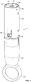
- Figures 1 to 4 show a first cassette unit 1 of an auto-injector herein arranged for use with a 1ml syringe 10 that contains a liquid drug formulation (not shown).
- the cassette unit 1 comprises an elongate form cassette unit housing 20 having an end cap 40 that is arranged for receipt of the syringe 10 and is sized and shaped for this purpose.
- the cassette unit housing 20 is provided with a viewing window 22 that allows for viewing of a 'used cassette flag' 33 provided to inner housing sleeve 30 to provide a visual indication of use, the operation of which will be described in more detail hereinafter.
- the cassette unit housing 20 is further provided with security label 21, which may in aspects be an RFID tag label for use in verification purposes.
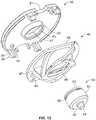
- the cassette unit 1 is provided with a removable cap 50 that is arranged to engage the needle cover 19 of the syringe 10 that is shown at Figures 1 and 2 in the capped position.
- the cap 50 is provided at the brim thereof with a peripheral arrangement of through-hole (i.e. socket like) first engagement features 52 (not visible on Figure 2 ).
- the cap 50 is shaped to define a ring pull 54 for receipt by the finger of a user.
- Needle cover gripper 56 in the form of a cage-like (or 'flower') structure and defining plural gripping elements 58 arranged about a central hub 59 is further provided to the removable cap 50.
- Such gripping elements 58 are arranged for gripping of the rigid needle sheath shield 19 on removal of the removable cap 50 such that removal of the cap 50 also results in removal of the rigid needle sheath shield 19 and needle sheath 17 enclosed thereby, and hence, unsheathing of the needle tip 15.
- the gripping ring 54 of the removable cap defines a finger aperture to receive a patient's thumb or other preferred finger for pulling the removable cap away from the cassette unit 1 to expose the needle 14.
- the finger aperture is adapted to receive a hook that some patients use to pull the removable cap 50 away from the cassette unit 1.
- the removable cap 50 with gripping ring 54 makes it easier for patients to engage and disengage the needle cover 17 and rigid needle shield 19 from the syringe barrel 12 as it does not require the patient to contort their fingers by pressing on the sides of a narrow needle cover 17/19.
- the present auto-injector is intended for use by patients having compromised manual dexterity who may therefore experience difficulty pulling a conventional needle cover 17 and/or rigid needle shield 19 off the syringe 10 before self-injection.
- the gripping ring 54 addresses this need by allowing the patient to simply put the thumb or other preferred finger through the finger aperture 54 and pull on the removable cap to thereby remove the needle cover 17 and rigid needle shield 19.
- the syringe 10 is of a standard 1ml type and comprises a barrel 12 with end flange 16 for holding a liquid drug formulation; a hollow needle 14 at one end of the barrel 12; and a syringe plunger 18 in the form of a rubber stopper that is arranged for axial movement within the barrel 12 such as to enable the liquid drug formulation to be expelled through the hollow needle 14.
- the syringe plunger 18 is at the 'pre- use' position.
- the hollow needle 14 defines a needle bore, which is of circular cross-section (e.g. 23G, 25G or 27G diameter) and a needle tip 15.
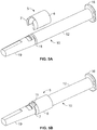
- the needle tip 15 is sheathed by needle sheath 17, which is also provided with rigid needle sheath shell 19. More detail of this relationship is now described by reference to Figures 6A to 7B , which illustrate an exemplary arrangement of needle sheath 17 and needle cover 19.
- Figure 6a depicts a perspective view of an exemplary embodiment of a sheath-like needle cover 17, which is cylindrical in shape and defines a shoulder 17a at the rear end.
- the needle sheath 17 may be made out of rubbery material that allows a portion of the connector 56 to dig into the outer surface thereof, such as that defined by the shoulder 17a to permanently engage the needle sheath 17 to the connector 56.
- Figure 6b shows a cross sectional view of the same needle sheath 17.
- the needle cover 17 includes a needle receiving portion 17b that is arranged in use, for piercing receipt of the tip 15 of the needle 14 as for example, shown at Figure 2 .
- the needle receiving portion 17b is made from butadiene rubber.
- the needle sheath 17 is hollow, but other shaped arrangements of the interior of the needle sheath 17 are also possible.
- FIGs 7a and 7b show views of a rigid needle shield 19 for use with the needle sheath 17 of Figure 6a and 6b .
- Rectangular openings 19a are provided at the rear end of the needle shield for receipt of the shoulder 17a of the needle sheath 17 to enable the forming of a needle cover as may be seen at Figure 2 .
- the cassette unit housing 20 of the cassette unit 1 is arranged to define a cassette unit housing cavity that is sized and shaped for generally fixed receipt of the syringe 10.
- the cassette unit housing 20 defines at its forward end a needle delivery aperture 23 through which in use, the hollow needle 14 of the syringe 10 and a portion of the glass hub thereof protrudes on removal of the cap 50 there from.
- the cassette unit housing 20 defines at its rearward end an end cap 40 adjacent to which the end flange 16 of the syringe 10 seats.
- the cassette unit housing 20 is provided with a radial arrangement of first engagement features in the form of movable locking legs 24 defining angled tips 25 (not visible on Figure 2 ) thereon arranged for reversibly engaging the corresponding radial arrangement of second engagement features in the form of socket through holes 52 of the removable cap 50 for reversible lock engagement of the removable cap 50 to the cassette unit housing 20.
- the cassette unit 1 is provided with an inner housing sleeve 30 for sleeved receipt of the syringe 10.
- the rear part of the inner housing sleeve 30 is provided with a spaced pair of rearward protruding arms 31.
- the inner housing sleeve 30 also forms a shuttle lock control feature 32 defining a radial arrangement of blocking elements 34 for selectively blocking movement of the movable locking legs 24 of the cassette unit housing 20 relative to the socket holes 52 of the cap 50, thereby providing for selective control of cap locking / unlocking, more details of which are described hereinafter with reference to Figures 8a to 11c .
- the syringe 10 of the cassette unit 1 additionally comprises a shoulder support feature 5 for supporting the forward shoulder 11 of the syringe.
- the shoulder support feature 5 may also used to adapt a 1ml syringe for use in the cassette unit 1. It supports the 1ml syringe shoulder 11, and transmits the load through to the same surface that would support a 2.25ml syringe shoulder directly.
- the shoulder support feature 5 may be seen to comprise a split-barrel 6 that is sized and shaped for receipt by the syringe barrel 12 and a forward split lip 7 that is arranged to locate in snap-fit fashion between the rigid needle sheath shell 19 and the forward shoulder 11 of the syringe 10.
- the use of such a shoulder support feature 5 is to adapt the smaller diameter 1ml syringe to the rigid shell 19 designed to support the 2.25ml syringe shoulder 11. Provision may also made for poor dimensional control in the production of glass syringes.
- the shoulder support feature 5 for the syringe 10 interacts with the inner wall of the cassette unit housing 20, which thereby acts to constrain the position of the shoulder support feature 5 and syringe 10 within the cassette unit housing 20.
- the inner wall of the cassette unit housing 20 also prevents the forward split lip 7 of the shoulder support feature 5 from flexing outwards when injection loads are applied to the syringe 10.
- the forward shoulder 11 of the syringe 10 effectively captures the forward split lip 7 of the shoulder support feature.
- the rearward split-barrel part 6 of the shoulder support feature 5 acts to sleeve a portion of the syringe barrel 12.
- shoulder support feature 5 may also effectively be used as a syringe size adapter feature.
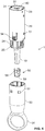
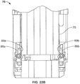
- the syringe plunger 18 is provided with a plunger slaving part 60 that is axially movable within the syringe barrel 12 and for receipt by the rear end of the plunger 18.
- the syringe plunger 18 is made of a material that is resiliently compressible and the plunger slaving part 60 is made of a less compressible material, typically a rigid material.
- the plunger slaving part 60 defining a circumferential wall 62 arranged for frictional sliding relationship with the inner wall 12a of the syringe barrel 12, a rear drive-receiving face 63 and a front plunger-contacting face 64.
- the slaving part 60 is arranged to function such that when a load is applied to its drive-receiving face 63 the load is evenly transmitted directly into the plunger 18.
- the rear drive-receiving face 63 of the plunger slaving part 60 has a central recess 65 for receipt of a drive transfer element.
- the central recess 65 is shaped such that the drive transfer element is rotatably receivable therein and has a recess form 65 that tapers to a square-cut end 66.
- the front plunger-contacting face 64 defines a protruding plug end 67 that is arranged for receipt by the rear end of the syringe plunger 18.
- the plug end 67 is designed to prevent collapse in use, of the plunger 18, which has a cavity in its centre into which a plunger rod may be screwed for manual syringe applications.
- the circumferential wall 62 of the plunger slaving part is provided with an evenly spaced radial arrangement of slide restrictors 68 that function to restrict frictional sliding movement thereof in relation to the inner wall of the syringe barrel 18.
- Each of the slide restrictors comprises a flexible vane 68 arranged to flex slightly in response to frictional sliding movement of the plunger slaving part 60 and to thereby to increase the resistance of the plunger slaving part 60 to frictional sliding movement.
- the flexible vanes 68 are arranged to increase the initial resistance to forward frictional sliding movement but to impart lesser resistance to said forward frictional sliding movement once movement is underway.
- the flexible vanes 68 are arranged to more greatly increase the resistance to a backward frictional sliding movement than to the forward frictional sliding movement.
- the slaving part 60 is coloured and performs a second function of providing an easy-to-identify visual indicator of the position of the plunger 18 within the syringe 10 so that the patient can visually confirm the drug had been fully injected.
- the flexible vanes 68 act such as to maintain the plunger slaving part 60 in the 'after use' (i.e. post-injection) position such that this indicator can be relied upon to signal this 'after use' state.
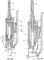
- the cassette unit 1 includes, in capping relationship with a rear opening of the cassette unit housing 20, a cassette unit end-cap 40. Further structural details of the cassette unit end-cap 40 may be seen by reference to Figures 12 and 13 .
- the cassette unit end-cap 40 defines a drive rod-receiving opening 41 for receipt of a drive rod (part of the drive unit, not shown) for providing forward axial drive to the plunger slaving part 60.
- Four fixing legs 39 with heels 38 locate at spaced intervals about the inner end wall of the end-cap 40 and protrude forwards for fixing receipt (not visible on Figure 13 ) with fixing sockets 29 of the cassette unit housing 20.
- the cassette unit end cap 40 also defines a spaced pair of cut-away apertures 51 positioned such that when the cassette unit end-cap 40 is in capped relationship with the cassette unit housing 20 the cut-away apertures 51 are in registration with the protruding arms 31 of the inner housing sleeve 30.
- Each cut-away aperture 51 is designed allow for insertion of a pushing member (e.g. a pin) such that forward pushing force may be applied to the top of the protruding arms 31 to push the inner housing sleeve 30 forward, thereby allowing for actuation of the shuttle lock control 32, as described in more detail hereinafter.
- a pushing member e.g. a pin
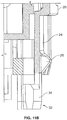
- the plunger slaving part 60 is in releasable engagement with the cassette unit end-cap 40.
- the drive rod-receiving opening 41 is defined by a periphery, which is provided with a forward skirt 42 and the plunger slaving part 60 is shaped for releasable engagement in the pre-use configuration with the forward skirt 42.
- the forward skirt 42 is provided with an inner-facing rim 43 and the plunger slaving part 60 defines a circumferential rim 61 and trough 69 shaped for releasable engagement in the pre-use configuration with the inner-facing rim 43 of the end-cap 40.
- the plunger slaving part 60 is releasable from the cassette unit end-cap 40 in response to forward axial drive provided to said rear drive-receiving face 63, 66 thereof.
- the cassette unit 1 additionally comprises an end-cap spring 45 defining a sprung biasing relationship between the cassette unit end-cap 40 and the flange 16 of the syringe 10, thereby urging the syringe 10 forwards in relation to the cassette unit end cap 40.
- the effect of this sprung relationship is to better hold the syringe 10 within the cassette unit housing 20, and in particular to minimize any potential for the syringe to 'rattle about' within the cassette unit housing 20.
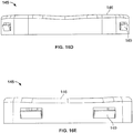
- end-cap spring 45 which is typically comprised of a polymeric material, may be seen by reference to Figures 12 , 13 and 15a to 15d .
- the rear end 46 of the end-cap spring 45 defines an essentially flat profile, which allows it to seat up against the inner end wall of the end-cap 40 where it is held in place by the interaction of pegs 44 on the inner wall of the end-cap 40 with peg-sockets 49 on the rear end 46 of the end-cap spring 45.
- Sprung arms 47 extends forwards in spiral fashion and meet at circular ring 48 at the forward end of the end-cap spring 45.
- this ring 48 is sized and shaped to fit about the forward skirt 42 of the end-cap 40 and when the plunger slaving part 60 is engaged with the end-cap 40 (e.g. as shown at Figures 2 and 13 ) about the outer circumferential wall 62 of the plunger slaving part 60.
- an alternative end-cap spring 145 is constructed from metal. Whilst the detailed shaping of this alternative end-cap spring 145 varies from that of the end-cap spring 45 of Figures 15a to 15d its function is the same.
- the rear end 146 of the alternative end-cap spring 145 defines an essentially flat profile, which allows it to rest a small distance away from the inner end wall of the end-cap 40.
- This alternative end-cap spring is held in place by the interaction of the inner side wall of the cassette unit housing 20 with clips 149 on the side wall of the alternative end-cap spring 145.
- Sprung arms 147 extends forwards in part-spiral fashion about a central ring aperture 148.
- this ring aperture 148 is sized and shaped to fit about the forward skirt 42 of the end-cap 40 and when the plunger slaving part 60 is engaged with the end-cap 40 (e.g. at a position corresponding to that shown at Figures 2 and 13 ) about the outer circumferential wall 62 of the plunger slaving part 60.
- a second alternative end-cap spring 245 is constructed from a ring of a resiliently flexible material such as a rubbery, foamed or sponge-like material. Again, whilst the detailed shaping of this second alternative end-cap spring 245 varies from that of the end-cap spring 45 of Figures 15a to 15d its function is the same.
- the rear end wall 246 of the alternative end-cap spring 245 defines an essentially flat profile, which allows it to seat up against the inner end wall of the end-cap 40.
- the alternative end-cap spring is held in place by the interaction of the inner side wall of the end-cap 40 and/or with pegs 249 on the rear end wall of the alternative end-cap spring 245.
- the body of the end-cap spring comprises a ring of material arranged about a central ring aperture 248.
- this ring aperture 248 is sized and shaped to fit about the forward skirt 42 of the end-cap 40 and when the plunger slaving part 60 is engaged with the end-cap 40 (e.g. at a position corresponding to that shown at Figures 2 and 13 ) about the outer circumferential wall 62 of the plunger slaving part 60.
- Figure 8c shows the separate cassette unit housing 20 and shuttle lock control 32 parts of the part-assembly of Figures 8a and 8b .
- the cassette unit housing 20 is provided with a radial arrangement of first engagement features in the form of axially protruding locking legs 24 having heels defining angled tips 25 movable by flexing action and arranged for reversibly engaging a corresponding radial arrangement of second engagement features in the form of socket through holes 52 of the removable cap 50 (see Figures 3 and 4 ) for reversible lock engagement of the removable cap 50 to the cassette unit housing 20.
- this arrangement also acts to prevent rotation of the cap 50 relative to the cassette unit housing 20.
- the inner housing sleeve 30 defines a shuttle lock control feature 32 comprising a radial arrangement of blocking elements 34 for selectively blocking inwardly flexing movement of the movable locking legs 24 of the cassette unit housing 20 relative to the socket holes 52 of the cap 50, thereby providing for selective control of cap locking / unlocking.
- the shuttle lock control 32 is axially movable relative to the cassette unit housing 20 in between three positions, namely:
- Movement of the shuttle lock control 32 is typically achieved by application of forward pushing force to the top of the protruding arms 31 of inner housing sleeve 30 to push the inner housing sleeve 30 and the shuttle lock control 32 forward.
- This is typically achieved by insertion of a pushing member (e.g. a pin) into each of the cut-away apertures 51 of the cassette unit end cap 40 to push forward the protruding arms 31 of the inner housing sleeve 30.
- the shuttle lock 32 is biased by the action of shuttle lock spring 35 from the second position to the third position.
- shuttle lock spring 35 on removal of the removable cap 34 the shuttle lock 32 is in the second position; during use of the cassette for injection the shuttle lock 32 is biased into the third position; and during replacement of the removable cap 50 the shuttle lock is in the second position.
- the shuttle lock control 32 is further provided with a pair of diametrically oppositely located axial position locators 36, each of which is arranged to define three distinct axial positions of the shuttle lock control 32 relative to cassette unit housing 20 and corresponding to said first, second and third positions.
- Each axial position locator 36 comprises an axial protrusion having a follower 37 arranged thereon for receipt within a corresponding axial track 26 of the inner cassette unit housing 20 such as to define an axial track-follower relationship between the shuttle lock control 32 / inner housing sleeve and the cassette unit housing 20.
- the previously defined first and second positions correspond to the opposite extremes of this axial track-follower relationship.
- each axial position locator 36 further comprises a first latch element in the form of an axial latching slot 38 arranged for selective latching relationship with a corresponding second latch element in the form of a latching foot 27 of the cassette unit housing 20.
- the latching foot 27 of the cassette unit housing 20 is movable within the axial latching slot 38 of the axial position locator 36 such as to define an axial foot-in-slot relationship between these parts.
- a non-return feature is also provided and arranged such that when the first and second latch elements 38, 27 have come into latching relationship return to a non-latching relationship is prevented.
- a forward ramped surface 39 is provided at the forward end of the first latch element, in which the axial latching slot 38 is defined, and a corresponding ramped surface 28 is defined at latching foot 27 such as to facilitate ramping over each other when coming into latching relationship.
- the latching foot 27 has been received within the axial latching slot 38 (second and third positions, see Figures 10b and 10c ) it is retained there and may not return to the first position ( Figure 10a ).
- the cassette unit 1 is initially in the first 'cassette unused' position, in which the angled tip 25 of each flexibly resilient locking leg 24 of the cassette unit housing 20 protrudes slightly into a socket through-hole first engagement feature 52 of the removable cap 50. It will be appreciated that this engaging interaction of the angled tip 25 of locking leg 24 with socket through-hole feature 52 effectively prevents movement (including rotation) of the cap 50 relative to the cassette unit housing 20.
- the blocking elements 34 block movement of the locking legs 24 of the cassette unit housing 20 relative to the socket through holes 52 of the removable cap, thereby keeping the removable cap 50 in locked relationship to the cassette unit housing 20.
- this engaging interaction can be released by pushing each locking leg 24 inwards, thereby clearing the angled tip 25 from engaging relationship with each relevant socket through-hole 52.
- Such inward pushing action on the locking leg 24 can be achieved (in the cap unlocked position of Figures 9b , 10b and 11b ) by pulling the cap 50 forwards and away from the cassette unit housing 20, which results in the angled tip 25 interacting with the wall edges of the through-hole 52 to push the locking leg 24 inwards.
- shuttle lock spring 35 After cap removal and during injected use, the action of shuttle lock spring 35 results in adoption of the third position until such time as the removable cap 50 is replaced when the second position is again adopted during cap 50 replacement. After cap replacement, the third position is again adopted.
- the shuttle lock control 32 is marked with a 'used cassette' flag 33 arranged to be brought into registration with the indicator opening of the cassette unit housing 20 at the third 'cassette used' position (see Figure 8b ) as a visual indicator that the cassette has been used.
- the alternative inner housing sleeve 330 incorporates a safety feature for preventing unintended movement (e.g. of the shuttle lock control 332 part thereof) relative to the cassette unit housing 20, which may potentially arise as a result of impact (e.g. from dropping of the cassette unit 1 or shock impact during transit thereof).
- the safety feature prevents unintended downwards movement of the inner housing sleeve 330 relative to the cassette unit housing 20 against the shuttle lock spring 35 from the first 'cassette unused' position to the third 'cassette used' position.
- This safety feature thereby prevents the 'used cassette' flag 333 of the inner housing sleeve from being moved in unintended fashion into registration with the indicator opening of the cassette unit housing 20, which would give a false visual indicator that the cassette 1 has been used.
- Figures 26 and 27 show views of the alternative inner housing sleeve 330 with its 'used cassette' flag 333.
- the alternative housing sleeve defines a shuttle lock control feature 332 comprising a radial arrangement of blocking elements 334 for selectively blocking inwardly flexing movement of the movable locking legs 24 of the cassette unit housing 20 relative to the socket holes 52 of the cap 50, thereby providing for selective control of cap locking / unlocking.
- the shuttle lock control 332 is provided with a pair of diametrically oppositely located axial position locators 336, each of which is arranged to define three distinct axial positions of the shuttle lock control 332 relative to cassette unit housing 20 and corresponding to said first, second and third positions.
- Each axial position locator 336 comprises an axial protrusion having a follower 337 arranged thereon for receipt within a corresponding axial track 26 of the inner cassette unit housing 20 such as to define an axial track-follower relationship between the shuttle lock control 32 / inner housing sleeve and the cassette unit housing.
- the previously defined first and second positions correspond to the opposite extremes of this axial track-follower relationship.
- each axial position locator 336 of the alternative inner housing sleeve 330 further comprises a first latch element in the form of an axial latching slot 338 arranged for selective latching relationship with a corresponding second latch element in the form of a latching foot 27 of the cassette unit housing 20.
- the latching foot 27 of the cassette unit housing 20 is movable within the axial latching slot 338 of the axial position locator 336 such as to define an axial foot-in-slot relationship between these parts.
- a non-return feature is also provided and arranged such that when the first and second latch elements 338, 27 have come into latching relationship return to a non-latching relationship is prevented.
- a forward ramped surface 339 is provided at the forward end of the first latch element, in which the axial latching slot 338 is defined, and a corresponding ramped surface 28 is defined at latching foot 27 such as to facilitate ramping over each other when coming into latching relationship. It will be appreciated that the interaction of axial position locator 336, axial latching slot 338 and forward ramped surface with corresponding parts 27, 28 of the cassette unit housing 20 is as described previously with particular reference to Figures 10a to 10c .
- the alternative inner housing sleeve 330 further includes a flexible latching arm 3100 arranged for selective safety latching action with part of the inner cassette unit housing 20, which safety latching action is now described by particular reference to Figures 28a to 28c .
- the flexible latching arm 3100 is hinged at hinge point 3102 such that it may move within the horizontal plane (i.e. the plane of the printed page).
- Raised central portion 3104 of the latching arm 3100 is arranged for push-receiving interaction with inwardly protruding nib 94a of flexible locking arms 94 of cassette unit housing 20.
- Slot-form cavity 3105 (see also Figures 26 and 27 ) is arranged for safety locking interaction with inner safety locking protrusion 20a of cassette unit housing 20.
- Far end of flexible latching arm 3100 is provided with finger 3106 arranged for non-return latching action with catch 3108.
- Figure 28a shows the latching arm 3100 in the 'pre use' position, in which the raised central portion 3104 thereof rests up against inwardly protruding nib 94a of flexible locking arms 94 of cassette unit housing 20, and in which end finger 3106 is spaced from (and therefore not in latching engagement with) catch 3108.
- inner safety locking protrusion 20a of cassette unit housing 20 is in safety blocking interaction with the proximal rib 3105 of the flexible latching arm 3100.
- Unintended movement (e.g. as a result of shock arising from dropping the cassette unit 1) of the alternative inner housing sleeve 330 relative to the cassette unit housing 20 is thereby, prevented.
- Figure 28b shows the latching arm 3100 in the intermediate 'safety latch releasing' position, in which inwardly protruding nib 94a of flexible locking arm 94 of cassette unit housing 20 has been pushed in (as the cassette unit 1 is inserted into cassette unit holder 75 of drive unit 70) and is accordingly pushed up against raised central portion 3104 of the flexible latching arm 3100.
- the flexible latching arm 3100 therefore flexes inwards (i) to move end finger 3106 into non-return latching engagement with catch 3108; and (ii) to move inner safety latching protrusion 20a of cassette unit housing 20 out of safety blocking interaction with proximal rib 3105 of the flexible latching arm 3100. Movement of the alternative inner housing sleeve 330 relative to the cassette unit housing 20 is as a result now possible.
- Figure 28c shows the latching arm 3100 in the 'safety latch released' position, in which (i) end finger 3106 is in non-return latching engagement with catch 3108; and (ii) inner safety latching protrusion 20a of cassette unit housing 20 is not in safety blocking interaction with proximal rib 3105 of the flexible latching arm 3100. Movement of the alternative inner housing sleeve 330 relative to the cassette unit housing 20 is as a result now possible.
- the cassette unit 1 further comprises flexible locking arms 94 for locking receipt within locking apertures 96 of a cassette unit holder 75 of a drive unit, as will be described hereinafter.
- FIG 17 shows a drive unit 70 for use with the cassette unit 1 described herein.
- the drive unit 70 comprises a drive unit housing 71 for housing a drive arrangement 80, which drive unit housing 71 is sized and shaped at its forward end for receipt of a cassette unit 1.
- Figure 18 shows the drive unit 70 having received a representative cassette unit 1 at the docking position, wherein ring pull 54 of the removable cap 50 protrudes from the drive unit housing 71.
- the drive unit housing 71 is provided with a user-interface in the form of a screen 72, which may in embodiments be a touch-sensitive screen 72.
- Figures 19 and 20 shows the inner workings of the drive unit 70 of Figures 17 and 18 , which has been configured in particular for use with the first cassette unit 1 herein.
- User-interface 72 may be seen to communicate with circuit board 74, which comprises electronic system circuitry that provides electronic control for the drive arrangement 80 and data processing capability. Further details of a representative electronic control system herein are later described by reference to Figure 21 .
- the circuit board 74 may also include inputs from various sensors and other electronic components including radiofrequency ID tag reader 73, which locates on cassette unit holder 75 and which is arranged for radiofrequency interrogation of an RFID tag on the cassette unit 1. In other embodiments, the radiofrequency ID tag reader 73 locates at the drive unit at a position closer to where the cassette unit 1 is arranged for receipt.
- the cassette unit 1 is received and held within the drive unit housing 71 by cassette unit holder 75, which is received within inner holder frame 77, which in turn seats at forward frame end 76, which defines a cassette-unit receiving aperture / needle delivery aperture 76a therein.
- Cassette unit holder 75 mounts within frame 77 and is axially (e.g. slidably) movable therein under the selective drive action of first motor 82.
- the first motor 82 e.g. stepper motor
- That worm 82b interacts with a rack locating on the back of cassette unit holder 75 to axially move the cassette unit holder 75 and cassette unit 1 and syringe 10 held thereby within the frame 77 from a rest position, in which the needle 14 with tip 15 of the syringe 10 is within the drive unit housing 71 to a use position, in which the needle 14 with tip 15 protrudes from the needle delivery aperture 76a of the drive unit housing.
- Second motor 85 selectively communicates via second gears 83a, 83b to a second drive transfer element in the form of a threaded screw 83c having cover 79 for subsequently transferring axial drive to the plunger 18 of the syringe 10 for moving the plunger 18 within the barrel 12 of the syringe 10 to eject at least part of the volume of liquid drug formulation contained therein.
- the drive unit 70 is arranged for sequential receipt of a cassette unit 1 herein.
- the drive unit 70 is arranged for initial receipt of the cassette 1 at an intermediate pre-docking position and for subsequent transport of the cassette unit 1 to the docking position.
- the drive unit 70 is arranged such that transport of the cassette unit 1 to the docking position is permitted only following positive verification of the identifier 21. Thus, only appropriately identified cassette units 1 are finally receivable into the device to enable injected drug delivery there from.
- the drive unit 70 is arranged such that transport of the cassette unit 1 from an intermediate position to a docking position is permitted only following positive verification of the identifier 21. Thus, only appropriately verified cassette units are finally receivable into the device for drug delivery there from.
- that transport of the cassette unit 1 to the docking position is by automatic control under the action of the electrically powered source of drive 82.
- positive verification of the cassette unit 1 gives rise to a 'transport to docking position' signal from the electronic control unit 74; 1001 to the source of drive, which results in the required transporting action.
- FIG 21 shows aspects of a typical electronic control system 1001 herein.
- Main microprocessor control unit (MCU) 1010 communicates with the following:
- the timer function 1090 of the MCU 1010 is initiated by the removal of the removable cap 50 and needle cover 17, 19 from the cassette unit 1.
- cap detect switch 1080 detects removal of the removable cap 50 (e.g. together with needle cover 17 and rigid needle shield 19) from the cassette unit 1.
- the timer 1090 then starts counting.
- a command to cancel the injection e.g. by preventing the action of the drive / motor function of the drive unit 70
- Drive action of the drive unit 70 is thus, prevented.
- the timer 1090 therefore acts to ensure that drug is delivered to the patient within a set time limit following removal of the removable cap 50 (e.g.
- timers examples include time or actuation-based counters installed on an integrated circuit chip, such as an 'elapsed time counter' such as the DS1602 IC manufactured by Dallas Semiconductor.
- the cassette unit 1 is selectively locked into the cassette unit holder 75 by the interaction of engaging tips 95 of locking arms 94 with the locking apertures of the cassette unit holder 75.
- Selective locking / unlocking is under the control of sprung-loaded cassette unit-unlock cams 88a, 88b, the function of which will now be described in relation to Figures 22a to 22c , which for clarity, do not show the cassette unit 1, but only the relevant drive unit 70 parts.
- Figure 22a shows the cassette unit holder 75 in the docking position, in which the cams 88a, 88b are spring-biased to the 'cassette unit 1 unlocked' position wherein the rounded heads 89a, 89b of each cam 88a, 88b are upright.
- the position corresponds to that, in which the removable cap 50 is unlocked, as further shown at Figures 23e and 24e .
- Figure 22b shows the cassette unit holder 75 moved forwards, but not yet engaging the cams 88a, 88b.
- the rounded heads 89a, 89b of each cam 88a, 88b remain upright.
- the position corresponds to that, in which the cassette unit 1 is inserted into the drive unit 70 for verification, as further shown at Figures 23c and 24c .
- Figure 22c shows the cassette unit holder 75 moved further forwards such as engage the cams 88a, 88b and to rotationally drive the rounded heads 89a, 89b of each cam 88a, 88b into a 'head bowed' position.
- the cams 88a, 88b may interact with the engaging tips 95 of locking arms 94 of the cassette unit housing 20 out of locking engagement with the locking aperture and thus, to allow the cassette unit 1 to be released from the cassette unit holder 75.
- the position which is the forward-most position of the cassette unit holder in use, corresponds to that, in which the cassette unit 1 may be ejected from the drive unit 70 after injected use, as further shown at Figures 23i and 24i .
- first auto-injector device herein may now be appreciated by reference to Figures 23a to 23i and Figures 24a to 24i and to the following description of a typical use operation:
- Figures 23a to 23i and Figures 24a to 24i show and describe sequential use steps of a first drive unit 70 essentially in accord with that already described by reference to Figures 17 to 20 as particularly used in conjunction with a first cassette unit 1 essentially in accord with that already described by reference to Figures 1 to 4 .
- the first drive unit 70 includes an electronic control system (not shown) essentially of the type described by reference to Figure 21 .
- Figures 23a to 23i and 23a to 23i most relevant to the use operation being described are identified by labelling.
- the auto-injector device is in the 'powered down' state as shown at Figures 23a and 24a , to which it returns after completion of a full use sequence, as described hereinbelow.
- the cams 88a, 88b may interact with the engaging tips 95 of locking arms 94 of the cassette unit housing 20 out of locking engagement with the locking aperture and thus, to allow the cassette unit 1 (not shown) to be released from the cassette unit holder 75.
- the auto-injector device adopts the configuration as shown at Figures 23b and 24b , in which the drive unit 70 is initially in the 'cassette receipt' position.
- the cassette unit holder 75 has been withdrawn backwards slightly to the 'cassette receipt' position within frame 77. In this position, the cassette unit holder 75 no longer engages with the sprung cams 88a, 88b and the rounded heads 89a, 89b thereof are now biased back to a 'head upright' position.
- First drive transfer element in the form of worm drive 82b for movement of the cassette unit holder 75 sets it in the 'cassette receipt' position interacting (as visible in Figure 24b only) with rack 75a provided along one side of the cassette holder.
- Second drive transfer element in the form of threaded screw 83c located within cover 79, the threaded screw 83c serving as a plunger rod 81 (for plunging movement of the plunger 18 of the syringe 10) is in its 'at rest' position.
- the cassette unit 1 contains a syringe including a syringe plunger 18 that interfaces with the plunger rod 81 upon activation for delivering medication. Forward end of the plunger rod 81 is provided with tapering, round headed end-piece 91.
- the user inserts cassette unit 1 comprising syringe 10 and having removable cap 50 to the intermediate pre-docking position within the cassette unit holder 75 of the drive unit 70.
- Needle cover gripper 56 in the form of a cage-like (or 'flower') structure is provided to the removable cap 50 for gripping of the rigid needle sheath shield 19 and configured such that removal of the cap 50 also results in removal of the rigid needle sheath shield 19 and needle sheath 17 enclosed thereby, and hence, unsheathing of the needle tip 15.
- End-cap spring 45 defines a sprung biasing relationship between the cassette unit end-cap 40 and the flange 16 of the syringe 10, thereby urging the syringe 10 forwards in relation to the cassette unit end cap 40.
- Plunger slaving part 60 is in releasable engagement with the cassette unit end-cap 40. As will be described hereinafter, in use, the plunger slaving part 60 is released from the cassette unit end-cap 40 in response to forward axial drive provided by the plunger rod 81, 91 to a rear drive-receiving face thereof.
- the general function of the tapering, round-headed end-piece 91 of the plunger rod 81 is to give rise to a point load instead of a face load.
- the slaving part 60 is made of a hard material, thus acting to reduce friction and torsion loads on the system.
- the slaving part 60 is arranged to function such that when a load is applied to its top face the load is evenly transmitted directly into the syringe plunger 18.
- the slaving part 60 is coloured and performs a second function of providing an easy-to-identify visual indicator of the position of the plunger 18 within the syringe 10 so that the patient can visually confirm the drug had been fully injected.
- shuttle lock control 32 is in the first 'cassette unused' position and thus, the removable cap 50 is in the cap locked position (also see Figures 8a , 9a , 10a and 11a ).
- the inner face of the locking arm 26 of the cassette unit housing 20 is blocked, thereby preventing any inwards movement thereof and so effectively also thereby, preventing any disengagement of the angled tip 29 of that locking arm 26 from socket through-hole 52 of the removable cap 50.
- pushing member in the form of pin 78 is spaced from the cassette 1, but locates immediately above protruding arms 31 of the inner housing sleeve 30, which are thus accessible to it via cut-away apertures 51 of the cassette unit end cap 40. More typically, a spaced pair of pins 78 would be provided. It will be appreciated that relative movement of the cassette 1 towards the pin 78 (e.g.
- Verification of the cassette unit 1 occurs at this intermediate pre-docking position.
- RFID reader 73; 1050 (see Figures 19 to 21 ) of the drive unit interrogates RFID tag 21 (see Figure 3 ) of the cassette unit 1 and thereby, reads verification information from the RFID tag 21 of the cassette unit 1.
- verification can for example, be for the purpose of checking of drug and dosage information, checking that the drug is not past its expiry date and / or checking that the cassette unit 1 has not been used previously.
- the cassette unit holder 75 and cassette unit 1 held therein are drawn further up (i.e. transported) into the drive unit 70 to the docking position of third stage of a typical use operation of Figures 23d and 24d .
- Such drawing up is achieved by the drive action of worm drive 82b on rack 75a of the cassette unit holder.
- the worm drive 82b receives axial drive from first motor 82; 1042 via gear 82a in response to a command from motor drive circuits 1042 acting under the control of motor control MCU 1040, which in turn communicates with main MCU 1010.
- the shuttle lock control 32 is in the second 'cassette unlocked' position (having been pushed relatively forward by the interaction of protruding arms 31 with pushing pin 78) and thus, the removable cap 50 is in the cap unlocked position (also see Figures 9b , 10b and 11b ).
- the inner face of the locking arm 26 of the cassette unit housing 20 is no longer blocked.
- inwards movement of the locking arm 26 is no longer prevented and disengagement of the tip 29 of the locking arm 26 from socket through-hole 52 of the removable cap 50 is achievable by suitable inwards pushing action on the tip 29 / locking arm 26.
- Such inward pushing action on the locking arm 26 is achievable by pulling the cap 50 away from the cassette unit 1, which results in the angled tip 29 interacting with the wall edges of the socket through-hole 52 to push the locking arm 26 inwards.
- the screen 72; 1070 now displays an instruction to the user to remove the cap 50 of the cassette unit 1.
- the drive unit 70 is provided with a timer function 1090, which is initiated by the removal of the removable cap 50 from the cassette unit 1.
- Cap removal sensing means 1082 are provided to detect removal of the removable cap 50 from the cassette unit 1.
- the timer 1090 then starts counting. In embodiments, once the timer 1090 reaches a certain, pre-determined count a command to prevent the drive function 80 of the drive unit 70 is generated. Drive action of the drive unit 70 is thus, prevented.
- the timer therefore acts as a safety measure to ensure that drug is delivered to the patient within a set time limit following removal of the removable cap 50 from the cassette unit 1.
- a fourth stage of a typical use operation as shown at Figures 23e and 24e , the user has removed the cap 50 together with needle sheath 17 and rigid needle shield 19.
- the needle 14 with tip 15 of the syringe 10 is now uncovered, but still shrouded by the drive unit 70 and does not protrude from the exit aperture 76a thereof.
- the screen 72; 1070 now displays an instruction to the user to place the device (i.e. the exit aperture 76a thereof) against the injection site.
- electrodes 1085a, 1085b of capacitive touch sense controller e.g. skin sensor
- the screen 72; 1070 now displays an instruction to the user to initiate the injection by pressing the 'inject' button. In other embodiments, such initiation of the injection may be configured to occur automatically on sensing of the correct placing of the device at the injection site.
- ejection of drug from the syringe barrel 12 can commence.
- Such ejection in response to forward advancement of threaded screw 83c responsive to geared driving by gears 83a, 83b, which receive axial drive from second motor 85; 1046 in response to a command from motor drive circuits 1042 acting under the control of motor control MCU 1040, which in turn communicates with main MCU 1010.
- Threaded screw 83c via end-piece 91 is brought into forward driving contact with rear drive-receiving end of slaving part 60.
- the resulting forward advancement thereof results in release of the plunger slaving part 60 from the end-cap 40 and then in forward sliding movement of that slaving part 60 within the syringe barrel 12, which in turn results in plunging movement of the plunger 18 within the barrel 12 of the syringe 10 to expel the drug formulation contents through the tip 15 of the needle 14 and into the injection site (e.g. skin of the user).
- the slaving part 60 functions such that when a driving load is applied to its rear drive-receiving face 63, 66 by round headed end-piece 91 of threaded screw 83c the load is evenly transmitted directly into the syringe plunger 18.
- cassette unit holder 75 As the cassette unit holder 75 is returned forwards the leading edge thereof interacts with sprung-loaded cassette unit-unlock cams 88a, 88b to move them from their 'head upright' to 'head bowed' positions.
- sprung-loaded cassette unit-unlock cams 88a, 88b When in the 'head bowed' position the rounded head 89a, 89b of each cam 88a, 88b presses on engaging tip 95 of locking arm 94 to move that locking arm 94 out of locking engagement with the locking aperture and thus, to allow the cassette unit 1 to be released from the cassette unit holder 75.
- the screen 72; 1070 now displays a message instructing the user to remove the cassette unit 301 from the drive unit 70. The user accordingly removes the cassette unit 1.
- the screen 72; 1070 then displays a message confirming that the cassette removal operation is complete.
- a battery check and / or data communication step may also be performed.
- the user then hits the power button to turn the drive unit off and the drive unit is stowed in the position as shown at Figures 23a and 24a until powered-up for a subsequent injection operation.
- the auto-injector as described herein is suitable for the injected delivery of drug, particularly for the treatment and/or prophylaxis of a number of diseases, disorders or conditions, including infections (viral, e.g. HIV infection, bacterial, fungal and parasitic); endotoxic shock associated with infection; inflammatory diseases/autoimmunity such as osteoarthritis, rheumatoid arthritis, psoriatic arthritis, systemic lupus erythematosus (SLE), ankylosing spondilitis, COPD, asthma, Alzheimer's Disease, Crohn's disease, ulcerative colitis, irritable bowel syndrome and psoriasis; immune mediated inflammatory disorders of the central and peripheral nervous system such as multiple sclerosis and Guillain-Barr syndrome; graft-versus-host disease; organ transplant rejection; pain; cancer (including solid tumours such as melanomas, hepatoblastomas, sarcomas, squamous cell carcinomas, transitional cell
- cystic fibrosis and sickle cell anaemia growth disorders; epilepsy; treatment of infertility; heart disease including ischaemic diseases such as myocardial infarction as well as atherosclerosis and intravascular coagulation; bone disorders such as osteopenia and osteoporosis; and metabolic/idiopathic disease, e.g. diabetes.
- the syringe of the auto-injector herein contains a liquid drug formulation, which is designed for refrigerated rest (e.g. at from 2-8°C) and for injected delivery at room temperature (e.g. at or about 18-30°C).
- the viscosity of the liquid drug formulation is less than 120 mPa.s (120 centipoise), in embodiments less than 100 mPa.s (100 centipoise) at a delivery temperature of 20°C.
- Appropriate drugs may thus be selected from biologically active agents, including chemical entities, polysaccharides, steroids and, especially, naturally occurring and recombinant proteins, including glycoproteins, polypeptides and oligopeptides and polymeric derivatives thereof.
- Particular proteins, polypeptides and oligopeptides include hormones, such as insulin, epinephrine, norepinephrine, adrenocorticotrophin, somatotropin, erythropoietin and oxytocin; cytokines, such as lymphokines, chemokines and interleukins and receptors therefor, e.g.
- IFN interferon- ⁇ , IFN- ⁇ , IFN- ⁇ , granulocyte monocyte colony stimulating factor, tumour necrosis factor- ⁇
- growth factors such as nerve growth factor and platelet-derived growth factor
- enzymes such as tissue plasminogen activator
- immunoglobulins immunoglobulins.
- the auto-injector device herein has been found to be of particular utility where the drug is an immunoglobulin or a fragment thereof, especially a PEGylated or mPEGylated antibody fragment.
- liquid drug formulations herein are typically aqueous formulations, which comprise the drug in solution and additionally other optional formulation components, which may include buffers (e.g. lactate, acetate), NaCl, and pH modifiers (e.g. NaOH).
- buffers e.g. lactate, acetate
- NaCl e.g. NaOH
- pH modifiers e.g. NaOH
- the auto-injector device herein has been found to be of particular utility wherein the concentration of the drug (e.g. a therapeutic biologic type drug) in the liquid drug formulation is quite high.
- the drug e.g. a therapeutic biologic type drug
- the auto-injector device has been found to be of particular utility wherein the concentration of the drug is greater than 100mg/ml, particularly greater than 150mg/ml such as 200mg/ml.
Claims (15)
- Unité à cassette (1) à utiliser avec un auto-injecteur ayant une unité d'entraînement alimentée électriquement, ladite unité à cassette comprenant :un boîtier d'unité à cassette (20) définissant une cavité de boîtier d'unité à cassette et une ouverture de saillie d'aiguille (23) ;ladite cavité de boîtier d'unité à cassette recevant une seringue (10) comprenant :un cylindre (12) destiné à contenir un volume d'une formulation médicamenteuse liquide, ledit cylindre définissant une bride (16) à l'extrémité arrière de celui-ci et un épaulement avant (11) à l'extrémité avant de celui-ci ;une aiguille creuse (14) à une extrémité avant dudit cylindre, ladite aiguille creuse définissant une pointe d'aiguille (15) pour la distribution de ladite formulation médicamenteuse liquide ; etun piston (18) qui est mobile axialement à l'intérieur du cylindre,caractérisée en ce qu'elle comprend :axialement mobile à l'intérieur du cylindre pour un déplacement vers l'avant jusqu'en contact avec ledit piston, une partie d'asservissement de piston (60) définissant une paroi circonférentielle (62) agencée pour une relation de glissement avec frottement avec la paroi interne (12a) du cylindre, une face arrière de réception d'entraînement (63) et une face avant de contact avec le piston (64),ladite partie d'asservissement de piston étant agencée de telle sorte que lorsqu'une charge d'entraînement est appliquée à ladite face arrière de réception d'entraînement pour mettre la face avant de contact avec le piston en contact avec le piston, la charge d'entraînement est transmise uniformément au piston,ladite paroi circonférentielle étant pourvue d'un ou plusieurs limiteurs de glissement (68) qui limitent un déplacement par glissement avec frottement de celle-ci relativement à la paroi interne du cylindre.
- Unité à cassette selon la revendication 1, dans laquelle ledit ou lesdits limiteurs de glissement sont agencés pour accroître leur résistance à un déplacement par glissement avec frottement.
- Unité à cassette selon l'une ou l'autre des revendications 1 et 2, dans laquelle le ou chacun des limiteurs de glissement comprend une ailette souple agencée pour fléchir légèrement en réponse à un déplacement par glissement avec frottement de la partie d'asservissement de piston.
- Unité à cassette selon l'une ou l'autre des revendications 2 et 3, dans laquelle ledit ou lesdits limiteurs de glissement sont agencés pour accroître la résistance initiale à un déplacement par glissement avec frottement vers l'avant, mais pour opposer une moindre résistance audit déplacement par glissement avec frottement vers l'avant une fois que le déplacement est en cours.
- Unité à cassette selon l'une quelconque des revendications 1 à 4, dans laquelle le ou les limiteurs de glissement sont agencés pour accroître plus fortement la résistance à un déplacement par glissement avec frottement vers l'arrière qu'au déplacement par glissement avec frottement vers l'avant.
- Unité à cassette selon l'une quelconque des revendications 1 à 5, dans laquelle ledit ou lesdits limiteurs de glissement sont agencés à des intervalles uniformément espacés autour de la paroi circonférentielle.
- Unité à cassette selon l'une quelconque des revendications 1 à 6, dans laquelle la face avant de contact avec le piston de la partie d'asservissement de piston est agencée pour entrer en prise avec le piston, de préférence dans laquelle le diamètre de la partie d'asservissement de piston correspond au diamètre du piston.
- Unité à cassette selon l'une quelconque des revendications 1 à 7, dans laquelle la face arrière de réception d'entraînement de la partie d'asservissement de piston a une encoche centrale (65) pour la réception d'un élément de transfert d'entraînement, de préférence dans laquelle ladite encoche centrale est façonnée de telle sorte que ledit élément de transfert d'entraînement peut y tourner, de préférence dans laquelle ladite encoche centrale est de forme conique, de préférence dans laquelle ladite encoche centrale se rétrécit jusqu'à une extrémité coupée d'équerre (66) ou jusqu'à une extrémité en oreille.
- Unité à cassette selon l'une quelconque des revendications 1 à 8, dans laquelle le boîtier d'unité à cassette définit une entrée par l'arrière dans la cavité de boîtier d'unité à cassette, comprenant également, en relation de coiffe avec ladite entrée par l'arrière du boîtier d'unité à cassette, un embout d'unité à cassette (40), ledit embout d'unité à cassette définissant une ouverture de réception de tige d'entraînement (41) pour la réception d'une tige d'entraînement destinée à appliquer un entraînement axial vers l'avant à ladite partie d'asservissement de piston.
- Unité à cassette selon la revendication 9, dans laquelle, dans une configuration avant usage, la partie d'asservissement de piston est façonnée pour venir en prise de façon détachable avec l'embout d'unité à cassette.
- Unité à cassette selon la revendication 10, dans laquelle ladite ouverture de réception de tige d'entraînement est définie par une périphérie et ladite partie d'asservissement de piston est façonnée pour venir en prise de façon détachable dans ladite configuration avant usage avec ladite périphérie ou dans laquelle ladite ouverture de réception de tige d'entraînement est définie par un bord périphérique et ladite partie d'asservissement de piston est façonnée pour venir en prise de façon détachable dans la configuration avant usage avec ledit bord périphérique.
- Unité à cassette selon l'une quelconque des revendications 9 à 11, dans laquelle l'embout est agencé pour une relation d'emboîtement-pression avec le boîtier d'unité à cassette, de préférence comprenant également un élément de rappel (45 ; 145 ; 245) définissant une relation de rappel entre l'embout d'unité à cassette et la bride de la seringue, poussant ainsi la seringue vers l'avant relativement à l'embout d'unité à cassette.
- Unité à cassette selon l'une quelconque des revendications 1 à 12, comprenant également un ou plusieurs éléments de support d'épaulement (5) destinés à supporter ledit épaulement avant de la seringue, de préférence dans laquelle le ou les éléments de support d'épaulement sont définis par une ou plusieurs parties de support d'épaulement séparées placées sur la seringue, de préférence dans laquelle le ou les éléments de support d'épaulement comportent une forme cylindrique fendue (6) agencée pour être reçue par le cylindre de la seringue.
- Unité à cassette selon l'une quelconque des revendications 1 à 13, dans laquelle le boîtier reçoit une seringue contenant une formulation médicamenteuse liquide, de préférence dans laquelle la formulation médicamenteuse liquide comprend une formulation aqueuse d'un médicament thérapeutique de type biologique.
- Auto-injecteur comprenant :(a) une unité à cassette selon l'une quelconque des revendications 1 à 14 ; et(b) une unité d'entraînement (70) comprenant :un boîtier d'unité d'entraînement (71) définissant une cavité d'arrimage et une ouverture de distribution d'aiguille (76a), ladite cavité d'arrimage étant agencée pour recevoir en arrimant l'unité à cassette à une position d'arrimage, ladite unité à cassette et/ou ladite seringue étant alors mobiles depuis une position de repos dans laquelle la pointe d'aiguille de la seringue est à l'intérieur du boîtier d'unité d'entraînement jusqu'à une position d'utilisation dans laquelle la pointe d'aiguille fait saillie depuis ladite ouverture de distribution d'aiguille ; etun agencement d'entraînement (80), ledit agencement d'entraînement comprenantune ou plusieurs sources d'entraînement axial alimentées électriquement (82, 85) ;un premier élément de transfert d'entraînement (82b) destiné à transférer ledit entraînement axial à l'unité à cassette et/ou à la seringue pour faire avancer la seringue jusqu'à ladite position d'utilisation ; etun deuxième élément de transfert d'entraînement (83c) destiné à transférer ensuite l'entraînement axial à la partie d'asservissement de piston et par conséquent au piston de la seringue pour déplacer le piston à l'intérieur du cylindre de la seringue afin d'éjecter au moins une partie dudit volume de formulation médicamenteuse liquide.
Applications Claiming Priority (3)
| Application Number | Priority Date | Filing Date | Title |
|---|---|---|---|
| GB201213503A GB201213503D0 (en) | 2012-07-30 | 2012-07-30 | Auto-injector |
| GB201222353A GB201222353D0 (en) | 2012-12-12 | 2012-12-12 | Auto-injector |
| PCT/EP2013/065940 WO2014020001A1 (fr) | 2012-07-30 | 2013-07-29 | Auto-injecteur |
Publications (2)
| Publication Number | Publication Date |
|---|---|
| EP2879737A1 EP2879737A1 (fr) | 2015-06-10 |
| EP2879737B1 true EP2879737B1 (fr) | 2018-09-12 |
Family
ID=48875084
Family Applications (1)
| Application Number | Title | Priority Date | Filing Date |
|---|---|---|---|
| EP13741801.8A Active EP2879737B1 (fr) | 2012-07-30 | 2013-07-29 | Auto-injecteur |
Country Status (3)
| Country | Link |
|---|---|
| US (1) | US9757513B2 (fr) |
| EP (1) | EP2879737B1 (fr) |
| WO (1) | WO2014020001A1 (fr) |
Families Citing this family (37)
| Publication number | Priority date | Publication date | Assignee | Title |
|---|---|---|---|---|
| US8579866B2 (en) | 2008-01-11 | 2013-11-12 | Ucb Pharma, S.A. | Systems and methods for administering medication |
| US9393369B2 (en) * | 2008-09-15 | 2016-07-19 | Medimop Medical Projects Ltd. | Stabilized pen injector |
| EP2714144B1 (fr) | 2011-06-02 | 2016-08-10 | UCB Biopharma SPRL | Auto-injecteur |
| US9757513B2 (en) | 2012-07-30 | 2017-09-12 | Ucb Biopharma Sprl | Auto-injector |
| WO2014019999A1 (fr) | 2012-07-30 | 2014-02-06 | Ucb Pharma S.A. | Auto-injecteur |
| WO2014019997A1 (fr) | 2012-07-30 | 2014-02-06 | Ucb Pharma S.A. | Auto-injecteur |
| EP2879736B1 (fr) | 2012-07-30 | 2018-11-14 | UCB Biopharma SPRL | Auto-injecteur |
| EP2781230B1 (fr) | 2013-03-22 | 2019-08-21 | TecPharma Licensing AG | Dispositif de distribution de substances avec dispositif de signal |
| GB201314381D0 (en) | 2013-08-12 | 2013-09-25 | Ucb Pharma Sa | Injector |
| WO2015110533A2 (fr) | 2014-01-27 | 2015-07-30 | Ucb Biopharma Sprl | Auto-injecteur |
| WO2015110532A1 (fr) | 2014-01-27 | 2015-07-30 | Ucb Biopharma Sprl | Auto-injecteur |
| USD782033S1 (en) | 2014-03-03 | 2017-03-21 | Sanofi | Medicament injection device |
| ES2866078T3 (es) | 2015-08-27 | 2021-10-19 | E3D Agricultural Coop Association Ltd | Dispositivo de inyección automático reutilizable |
| JP2018537251A (ja) * | 2015-12-14 | 2018-12-20 | ケアベイ・ヨーロッパ・リミテッドCarebay Europe Limited | 薬剤送達装置 |
| JP6949037B2 (ja) * | 2016-02-08 | 2021-10-13 | ウエスト ファーマスーティカル サービシーズ インコーポレイテッド | 針シールドプラー |
| WO2017174672A1 (fr) | 2016-04-07 | 2017-10-12 | Ucb Biopharma Sprl | Auto-injecteur et unité d'entraînement associée |
| EP3448459A4 (fr) | 2016-04-28 | 2019-10-30 | Becton, Dickinson and Company | Magasin d'aiguilles de stylo |
| US11207470B2 (en) | 2016-04-28 | 2021-12-28 | Becton, Dickinson And Company | Pen needle exchange system |
| ES2897406T3 (es) | 2016-04-28 | 2022-03-01 | Becton Dickinson Co | Depósito de agujas para pluma |
| WO2017189165A1 (fr) | 2016-04-28 | 2017-11-02 | Becton, Dickinson And Company | Magasin d'aiguilles de stylo |
| EP3448454A4 (fr) | 2016-04-28 | 2019-10-23 | Becton, Dickinson and Company | Magasin de stockage d'aiguilles avec indication d'état |
| EP3448473B1 (fr) | 2016-04-28 | 2021-10-27 | Becton, Dickinson and Company | Magasin d'aiguilles de stylo |
| US11007312B2 (en) | 2016-04-28 | 2021-05-18 | Becton, Dickinson And Company | Pen needle magazine |
| JP6993349B2 (ja) | 2016-04-28 | 2022-01-13 | ベクトン・ディキンソン・アンド・カンパニー | ペンニードル交換システム |
| US11285257B2 (en) | 2016-04-28 | 2022-03-29 | Becton, Dickinson And Company | Pen needle magazine |
| CN109069763B (zh) | 2016-04-28 | 2021-05-28 | 贝克顿·迪金森公司 | 笔针仓 |
| CA3026818A1 (fr) | 2016-06-06 | 2017-12-14 | Tal PIKAN | Injecteur informatise a usages multiples |
| EP3369444A1 (fr) * | 2017-03-01 | 2018-09-05 | Sanofi-Aventis Deutschland GmbH | Dispositif d'emballage, dispositif d'injection d'un médicament et paquet d'urgence |
| GB201706697D0 (en) * | 2017-04-27 | 2017-06-14 | Ucb Biopharma Sprl | Cap for an injector |
| CN110869072B (zh) | 2017-05-30 | 2021-12-10 | 西部制药服务有限公司(以色列) | 用于穿戴式注射器的模块化驱动机构 |
| CA3079355C (fr) | 2017-10-16 | 2023-09-12 | Becton, Dickinson And Company | Detection de fin de dose pour systeme d'administration de medicament |
| US11040142B2 (en) * | 2018-03-12 | 2021-06-22 | E3D A.C.A.L Ltd | Automatic injection device with a dampening element |
| EP3626291A1 (fr) | 2018-09-21 | 2020-03-25 | Regeneron Pharmaceuticals, Inc. | Dispositifs de préhension de protection d'aiguille et procédés associés |
| US11219720B2 (en) * | 2018-10-08 | 2022-01-11 | Dali Medical Devices Ltd. | Safety needle with needle hub, and methods of use thereof |
| US11154663B2 (en) * | 2018-10-25 | 2021-10-26 | Sharps Technology Inc. | Pre-filled safety needle and syringe system |
| USD999906S1 (en) | 2021-06-24 | 2023-09-26 | UCB Biopharma SRL | Gripper for auto-injector needle shield |
| WO2023126249A1 (fr) * | 2022-01-03 | 2023-07-06 | Shl Medical Ag | Sous-ensemble d'une unité de cassette de médicament |
Family Cites Families (91)
| Publication number | Priority date | Publication date | Assignee | Title |
|---|---|---|---|---|
| US2966910A (en) | 1955-07-06 | 1961-01-03 | S & R J Everett & Co Ltd | Locking devices |
| US3395704A (en) | 1964-11-19 | 1968-08-06 | Frey Max | Power operated syringe |
| NL8701091A (nl) | 1987-05-08 | 1988-12-01 | Spruyt Hillen Bv | Injectiepen. |
| EP0518416A1 (fr) | 1991-06-13 | 1992-12-16 | Duphar International Research B.V | Dispositif d'injection |
| CA2157999C (fr) | 1994-09-23 | 1999-08-03 | Robert B. Odell | Dispositif protecteur a rotation manuelle pour element de percage |
| US5843036A (en) | 1996-08-23 | 1998-12-01 | Becton Dickinson And Company | Non-dosing cartridge for an injection device |
| US6368307B1 (en) | 1997-07-18 | 2002-04-09 | Liebel-Flarsheim Company | Front-loading power injector and method of loading flanged syringe therein |
| US5957896A (en) | 1997-08-11 | 1999-09-28 | Becton, Dickinson And Company | Medication delivery pen |
| USD439657S1 (en) | 1999-10-19 | 2001-03-27 | Baxter International Inc. | Push button fluid delivery controller |
| US6958053B1 (en) | 1999-11-24 | 2005-10-25 | Medrad, Inc. | Injector providing drive member advancement and engagement with syringe plunger, and method of connecting a syringe to an injector |
| AU2001280762A1 (en) | 2000-08-02 | 2002-02-13 | Becton, Dickinson And Company | Pen needle and safety shield system |
| IL156245A0 (en) | 2000-12-22 | 2004-01-04 | Dca Design Int Ltd | Drive mechanism for an injection device |
| US6558353B2 (en) | 2001-01-25 | 2003-05-06 | Walter A. Zohmann | Spinal needle |
| JP2004528939A (ja) | 2001-06-08 | 2004-09-24 | イーライ・リリー・アンド・カンパニー | 薬剤注射器のための針隠蔽アセンブリー |
| US6869418B2 (en) | 2001-08-17 | 2005-03-22 | Hypoguard Usa Inc. | Safety shield for a needle assembly |
| DK1432466T3 (da) | 2001-09-12 | 2012-12-03 | Becton Dickinson Co | Mikronål-baseret penapparat til lægemiddeludlevering og fremgangsmåde til anvendelse heraf |
| US7553294B2 (en) | 2002-05-30 | 2009-06-30 | Medrad, Inc. | Syringe plunger sensing mechanism for a medical injector |
| US7811260B2 (en) | 2002-05-31 | 2010-10-12 | Vidacare Corporation | Apparatus and method to inject fluids into bone marrow and other target sites |
| US7125394B2 (en) | 2002-06-04 | 2006-10-24 | Syringe, Llc | Applicator for dispensing a medicinal substance |
| US7141036B2 (en) | 2002-06-04 | 2006-11-28 | Syringe, Llc | Methods of applying a medicinal substance |
| EP1391794A1 (fr) | 2002-07-23 | 2004-02-25 | Novo Nordisk A/S | Dispositif muni d'indicateur de temps |
| DE60227115D1 (de) | 2002-11-06 | 2008-07-24 | Becton Dickinson Co | Passive nadelschutzvorrichtung für injektionsvorrichtungen |
| USD484244S1 (en) | 2002-11-26 | 2003-12-23 | Caribbean Medical Brokers, Inc. | Lancet cover |
| DE10351598A1 (de) | 2003-11-05 | 2005-06-16 | Tecpharma Licensing Ag | Autoinjektionsvorrichtung |
| PL1732629T3 (pl) | 2004-03-30 | 2019-10-31 | Lilly Co Eli | Urządzenie do dozowania leków z napędzaną sprężyną blokadą załączaną na skutek podania ostatniej dawki |
| JP4654180B2 (ja) | 2004-04-05 | 2011-03-16 | 株式会社根本杏林堂 | 薬液注入システム |
| ATE415181T1 (de) | 2005-02-23 | 2008-12-15 | Mallinckrodt Inc | Stützplattenadapter für einen spritzenkolben |
| USD543273S1 (en) | 2005-04-01 | 2007-05-22 | Meridian Medical Technologies, Inc. | Automatic injector |
| GB2425062B (en) | 2005-04-06 | 2010-07-21 | Cilag Ag Int | Injection device |
| GB2424836B (en) | 2005-04-06 | 2010-09-22 | Cilag Ag Int | Injection device (bayonet cap removal) |
| CN101187962A (zh) | 2005-04-06 | 2008-05-28 | 马林克罗特公司 | 管理有关医用液体及其容器的信息的系统与方法 |
| CN101437561B (zh) | 2006-03-21 | 2011-09-28 | 泰科保健集团有限合伙公司 | 用于注射装置的被动式栓锁环安全防护装置 |
| GB2437922B (en) | 2006-05-10 | 2010-12-08 | Owen Mumford Ltd | Injection device comprising a window and a shutter element |
| GB2438590B (en) | 2006-06-01 | 2011-02-09 | Cilag Gmbh Int | Injection device |
| GB2438593B (en) | 2006-06-01 | 2011-03-30 | Cilag Gmbh Int | Injection device (cap removal feature) |
| US20080171983A1 (en) | 2006-10-27 | 2008-07-17 | Knutson Eric J | Needle hub assembly |
| US8454560B2 (en) | 2006-12-05 | 2013-06-04 | Mallinckrodt Llc | Syringe mount for a medical fluid injector |
| CN101678168B (zh) | 2007-03-22 | 2013-03-06 | 特克法马许可公司 | 具有受控制的注射针拉回功能的注射装置 |
| JP5216859B2 (ja) | 2007-09-25 | 2013-06-19 | ベクトン・ディキンソン・フランス・エス.エー.エス. | 改変を証明する手段を有する遮へい分離部を備えた自動注射器 |
| CN101983079B (zh) | 2007-11-14 | 2014-07-02 | Shl集团有限责任公司 | 能主动触发针筒撤回的自动注射装置 |
| EP2227278B1 (fr) | 2007-11-21 | 2018-06-13 | Becton Dickinson France | Dispositif d'injection qui empêche le retour du piston lorsque les systèmes de sécurité sont déployés |
| GB0724906D0 (en) | 2007-12-20 | 2008-01-30 | Ucb Pharma Sa | Auto-injector |
| GB0800103D0 (en) | 2008-01-04 | 2008-02-13 | Owen Mumford Ltd | Sheath removver device |
| US8579866B2 (en) | 2008-01-11 | 2013-11-12 | Ucb Pharma, S.A. | Systems and methods for administering medication |
| CA2720452A1 (fr) | 2008-04-02 | 2009-10-08 | Laurimed, Llc | Procedes et dispositifs pour administrer des injections |
| CA2724641C (fr) | 2008-05-20 | 2020-03-24 | Avant Medical Corp. | Systeme d'auto-injection |
| US8048029B2 (en) | 2008-06-20 | 2011-11-01 | West Pharmaceutical Services, Inc. | Injector apparatus |
| WO2010007395A1 (fr) | 2008-07-18 | 2010-01-21 | Ucb Pharma S.A. | Systèmes d'administration de médicament pour patients atteints de polyarthrite rhumatoïde |
| US8262616B2 (en) | 2008-10-10 | 2012-09-11 | Deka Products Limited Partnership | Infusion pump assembly |
| DK2468344T3 (da) | 2008-10-13 | 2013-12-09 | Sanofi Aventis Deutschland | Lægemiddelafgivelsesindretning og fremgangsmåde til fremstilling af lægemiddelafgivelsesindretning |
| GB0901801D0 (en) | 2009-02-05 | 2009-03-11 | Medical House Plc The | Improved autoinjector |
| DE202009001836U1 (de) | 2009-02-13 | 2009-05-20 | Dieter Hölzle Technik-Projekte GmbH | Elektromechanische Injektionsvorrichtung |
| EP2401009B1 (fr) | 2009-02-26 | 2012-11-28 | Tecpharma Licensing AG | Support de réservoir à produit pour un dispositif d'injection et pour la réception d'un réservoir à produit |
| CN102300597B (zh) | 2009-03-04 | 2014-08-27 | 松下健康医疗器械株式会社 | 药剂注入装置 |
| WO2010136076A1 (fr) | 2009-05-29 | 2010-12-02 | Tecpharma Licensing Ag | Dispositif d'injection comprenant un système destiné à séparer un capuchon de protection d'aiguille d'un réservoir à produit |
| WO2010136078A1 (fr) | 2009-05-29 | 2010-12-02 | Tecpharma Licensing Ag | Dispositif d'injection, notamment auto-injecteur comprenant une protection contre la piqûre involontaire et/ou une sécurité contre la surcharge, pour un réservoir à produit |
| US9457150B2 (en) | 2009-06-01 | 2016-10-04 | Sanofi-Aventis Deutschland Gmbh | Biasing mechanism for a drug delivery device |
| EP2437816B1 (fr) | 2009-06-04 | 2013-04-24 | Novo Nordisk Health Care AG | Dispositif de mélange avec un piston/inter-verrouillage de tige de piston |
| EP2442856B1 (fr) | 2009-06-17 | 2024-02-07 | SHL Medical AG | Agencement de porte-contenant de médicament |
| EP3865162B1 (fr) | 2009-07-10 | 2024-02-28 | Becton, Dickinson and Company | Ensemble seringue de rinçage |
| EP2478337B1 (fr) | 2009-09-18 | 2015-08-26 | Sanofi-Aventis Deutschland GmbH | Configuration pour déterminer une position longitudinale d'un élément d'arrêt |
| CA2778859A1 (fr) | 2009-10-30 | 2011-05-05 | Sanofi-Aventis Deutschland Gmbh | Dispositif d'administration de medicaments |
| USD636088S1 (en) | 2009-12-28 | 2011-04-12 | Miramar Labs, Inc. | Hand-held applicator for applying energy to a body tissue region |
| EP2569031B1 (fr) * | 2010-05-10 | 2017-10-11 | Medimop Medical Projects Ltd. | Injecteur précis de faible volume |
| CA2808469A1 (fr) | 2010-08-19 | 2012-02-23 | Sanofi-Aventis Deutschland Gmbh | Procede et systeme pour determiner des informations concernant un reservoir de medicament utilisant un capteur electronique |
| US9814846B2 (en) | 2010-08-26 | 2017-11-14 | Sanofi-Aventis Deutschland Gmbh | Method and system for determining information related to a drug reservoir |
| USD650070S1 (en) | 2010-09-16 | 2011-12-06 | Panasonic Corporation | Injector |
| TWI464002B (zh) | 2010-11-08 | 2014-12-11 | Shl Group Ab | 容器支撐總成和藥物輸送裝置總成 |
| EP2468341A1 (fr) | 2010-12-21 | 2012-06-27 | Sanofi-Aventis Deutschland GmbH | Auto-injecteur |
| CA2832033C (fr) | 2011-04-05 | 2016-02-09 | Shl Group Ab | Dispositif d'administration d'un medicament comportant un mecanisme de verrouillage muni d'un levier |
| USD652919S1 (en) | 2011-04-18 | 2012-01-24 | Conopco, Inc. | Laser handpiece |
| USD652513S1 (en) | 2011-04-18 | 2012-01-17 | Conopco, Inc. | Laser handpiece |
| USD652512S1 (en) | 2011-04-18 | 2012-01-17 | Conopco, Inc. | Laser handpiece |
| LT2699293T (lt) | 2011-04-20 | 2019-04-25 | Amgen Inc. | Automatinio purškimo prietaisas |
| USD671638S1 (en) | 2011-05-19 | 2012-11-27 | Oval Medical Technologies Limited | Autoinjector with removable cap |
| EP2714144B1 (fr) | 2011-06-02 | 2016-08-10 | UCB Biopharma SPRL | Auto-injecteur |
| BR112014000197B1 (pt) | 2011-07-05 | 2021-03-23 | Shl Medical Ag | Conjunto removedor de revestimento de agulha |
| US9302053B2 (en) | 2011-12-06 | 2016-04-05 | Shl Group Ab | Injection device |
| USD696770S1 (en) | 2012-04-13 | 2013-12-31 | Becton, Dickinson And Company | Autoinjector |
| USD724203S1 (en) | 2012-06-04 | 2015-03-10 | Ucb Pharma S.A. | Drive device for administering medication |
| JP1461242S (fr) | 2012-07-02 | 2016-02-01 | ||
| JP1461241S (fr) | 2012-07-02 | 2016-02-01 | ||
| WO2014019997A1 (fr) | 2012-07-30 | 2014-02-06 | Ucb Pharma S.A. | Auto-injecteur |
| EP2879736B1 (fr) | 2012-07-30 | 2018-11-14 | UCB Biopharma SPRL | Auto-injecteur |
| WO2014019999A1 (fr) | 2012-07-30 | 2014-02-06 | Ucb Pharma S.A. | Auto-injecteur |
| USD726901S1 (en) | 2012-07-30 | 2015-04-14 | Ucb Pharma S.A. | Drive device for administering medication |
| US9757513B2 (en) | 2012-07-30 | 2017-09-12 | Ucb Biopharma Sprl | Auto-injector |
| US8591463B1 (en) | 2013-03-08 | 2013-11-26 | Teva Pharmaceutical Industries Ltd. | Re-useable injector device for syringe |
| EP2978478B1 (fr) | 2013-03-25 | 2021-05-26 | SHL Medical AG | Bouchon avant pour dispositif d'administration de médicament |
| EP3099350B1 (fr) | 2014-01-27 | 2019-06-12 | UCB Biopharma SPRL | Auto-injecteur |
| WO2015110532A1 (fr) | 2014-01-27 | 2015-07-30 | Ucb Biopharma Sprl | Auto-injecteur |
-
2013
- 2013-07-29 US US14/418,441 patent/US9757513B2/en active Active
- 2013-07-29 WO PCT/EP2013/065940 patent/WO2014020001A1/fr active Application Filing
- 2013-07-29 EP EP13741801.8A patent/EP2879737B1/fr active Active
Also Published As
| Publication number | Publication date |
|---|---|
| EP2879737A1 (fr) | 2015-06-10 |
| US9757513B2 (en) | 2017-09-12 |
| WO2014020001A1 (fr) | 2014-02-06 |
| US20150182691A1 (en) | 2015-07-02 |
Similar Documents
| Publication | Publication Date | Title |
|---|---|---|
| EP2879737B1 (fr) | Auto-injecteur | |
| EP2879736B1 (fr) | Auto-injecteur | |
| US10639424B2 (en) | Auto-injector and drive unit therefor | |
| US9821123B2 (en) | Auto-injector | |
| US9764101B2 (en) | Auto-injector | |
| EP3099351B1 (fr) | Auto-injecteur | |
| US9789254B2 (en) | Auto-injector | |
| EP2879738B1 (fr) | Auto-injecteur | |
| US9669158B2 (en) | Auto-injector |
Legal Events
| Date | Code | Title | Description |
|---|---|---|---|
| PUAI | Public reference made under article 153(3) epc to a published international application that has entered the european phase |
Free format text: ORIGINAL CODE: 0009012 |
|
| 17P | Request for examination filed |
Effective date: 20150302 |
|
| AK | Designated contracting states |
Kind code of ref document: A1 Designated state(s): AL AT BE BG CH CY CZ DE DK EE ES FI FR GB GR HR HU IE IS IT LI LT LU LV MC MK MT NL NO PL PT RO RS SE SI SK SM TR |
|
| AX | Request for extension of the european patent |
Extension state: BA ME |
|
| RAP1 | Party data changed (applicant data changed or rights of an application transferred) |
Owner name: UCB BIOPHARMA SPRL |
|
| STAA | Information on the status of an ep patent application or granted ep patent |
Free format text: STATUS: EXAMINATION IS IN PROGRESS |
|
| REG | Reference to a national code |
Ref country code: DE Ref legal event code: R079 Ref document number: 602013043541 Country of ref document: DE Free format text: PREVIOUS MAIN CLASS: A61M0005200000 Ipc: A61M0005315000 |
|
| 17Q | First examination report despatched |
Effective date: 20180223 |
|
| GRAP | Despatch of communication of intention to grant a patent |
Free format text: ORIGINAL CODE: EPIDOSNIGR1 |
|
| STAA | Information on the status of an ep patent application or granted ep patent |
Free format text: STATUS: GRANT OF PATENT IS INTENDED |
|
| RIC1 | Information provided on ipc code assigned before grant |
Ipc: A61M 5/32 20060101ALI20180319BHEP Ipc: A61M 5/31 20060101ALI20180319BHEP Ipc: A61M 5/315 20060101AFI20180319BHEP Ipc: A61M 5/20 20060101ALI20180319BHEP |
|
| INTG | Intention to grant announced |
Effective date: 20180423 |
|
| GRAS | Grant fee paid |
Free format text: ORIGINAL CODE: EPIDOSNIGR3 |
|
| GRAA | (expected) grant |
Free format text: ORIGINAL CODE: 0009210 |
|
| STAA | Information on the status of an ep patent application or granted ep patent |
Free format text: STATUS: THE PATENT HAS BEEN GRANTED |
|
| AK | Designated contracting states |
Kind code of ref document: B1 Designated state(s): AL AT BE BG CH CY CZ DE DK EE ES FI FR GB GR HR HU IE IS IT LI LT LU LV MC MK MT NL NO PL PT RO RS SE SI SK SM TR |
|
| AX | Request for extension of the european patent |
Extension state: BA ME |
|
| REG | Reference to a national code |
Ref country code: GB Ref legal event code: FG4D |
|
| REG | Reference to a national code |
Ref country code: CH Ref legal event code: EP |
|
| REG | Reference to a national code |
Ref country code: IE Ref legal event code: FG4D |
|
| REG | Reference to a national code |
Ref country code: DE Ref legal event code: R096 Ref document number: 602013043541 Country of ref document: DE |
|
| REG | Reference to a national code |
Ref country code: AT Ref legal event code: REF Ref document number: 1039822 Country of ref document: AT Kind code of ref document: T Effective date: 20181015 |
|
| REG | Reference to a national code |
Ref country code: NL Ref legal event code: MP Effective date: 20180912 |
|
| REG | Reference to a national code |
Ref country code: LT Ref legal event code: MG4D |
|
| PG25 | Lapsed in a contracting state [announced via postgrant information from national office to epo] |
Ref country code: GR Free format text: LAPSE BECAUSE OF FAILURE TO SUBMIT A TRANSLATION OF THE DESCRIPTION OR TO PAY THE FEE WITHIN THE PRESCRIBED TIME-LIMIT Effective date: 20181213 Ref country code: NO Free format text: LAPSE BECAUSE OF FAILURE TO SUBMIT A TRANSLATION OF THE DESCRIPTION OR TO PAY THE FEE WITHIN THE PRESCRIBED TIME-LIMIT Effective date: 20181212 Ref country code: BG Free format text: LAPSE BECAUSE OF FAILURE TO SUBMIT A TRANSLATION OF THE DESCRIPTION OR TO PAY THE FEE WITHIN THE PRESCRIBED TIME-LIMIT Effective date: 20181212 Ref country code: FI Free format text: LAPSE BECAUSE OF FAILURE TO SUBMIT A TRANSLATION OF THE DESCRIPTION OR TO PAY THE FEE WITHIN THE PRESCRIBED TIME-LIMIT Effective date: 20180912 Ref country code: LT Free format text: LAPSE BECAUSE OF FAILURE TO SUBMIT A TRANSLATION OF THE DESCRIPTION OR TO PAY THE FEE WITHIN THE PRESCRIBED TIME-LIMIT Effective date: 20180912 Ref country code: RS Free format text: LAPSE BECAUSE OF FAILURE TO SUBMIT A TRANSLATION OF THE DESCRIPTION OR TO PAY THE FEE WITHIN THE PRESCRIBED TIME-LIMIT Effective date: 20180912 Ref country code: SE Free format text: LAPSE BECAUSE OF FAILURE TO SUBMIT A TRANSLATION OF THE DESCRIPTION OR TO PAY THE FEE WITHIN THE PRESCRIBED TIME-LIMIT Effective date: 20180912 |
|
| PG25 | Lapsed in a contracting state [announced via postgrant information from national office to epo] |
Ref country code: AL Free format text: LAPSE BECAUSE OF FAILURE TO SUBMIT A TRANSLATION OF THE DESCRIPTION OR TO PAY THE FEE WITHIN THE PRESCRIBED TIME-LIMIT Effective date: 20180912 Ref country code: HR Free format text: LAPSE BECAUSE OF FAILURE TO SUBMIT A TRANSLATION OF THE DESCRIPTION OR TO PAY THE FEE WITHIN THE PRESCRIBED TIME-LIMIT Effective date: 20180912 Ref country code: LV Free format text: LAPSE BECAUSE OF FAILURE TO SUBMIT A TRANSLATION OF THE DESCRIPTION OR TO PAY THE FEE WITHIN THE PRESCRIBED TIME-LIMIT Effective date: 20180912 |
|
| REG | Reference to a national code |
Ref country code: AT Ref legal event code: MK05 Ref document number: 1039822 Country of ref document: AT Kind code of ref document: T Effective date: 20180912 |
|
| PG25 | Lapsed in a contracting state [announced via postgrant information from national office to epo] |
Ref country code: PL Free format text: LAPSE BECAUSE OF FAILURE TO SUBMIT A TRANSLATION OF THE DESCRIPTION OR TO PAY THE FEE WITHIN THE PRESCRIBED TIME-LIMIT Effective date: 20180912 Ref country code: EE Free format text: LAPSE BECAUSE OF FAILURE TO SUBMIT A TRANSLATION OF THE DESCRIPTION OR TO PAY THE FEE WITHIN THE PRESCRIBED TIME-LIMIT Effective date: 20180912 Ref country code: AT Free format text: LAPSE BECAUSE OF FAILURE TO SUBMIT A TRANSLATION OF THE DESCRIPTION OR TO PAY THE FEE WITHIN THE PRESCRIBED TIME-LIMIT Effective date: 20180912 Ref country code: IS Free format text: LAPSE BECAUSE OF FAILURE TO SUBMIT A TRANSLATION OF THE DESCRIPTION OR TO PAY THE FEE WITHIN THE PRESCRIBED TIME-LIMIT Effective date: 20190112 Ref country code: CZ Free format text: LAPSE BECAUSE OF FAILURE TO SUBMIT A TRANSLATION OF THE DESCRIPTION OR TO PAY THE FEE WITHIN THE PRESCRIBED TIME-LIMIT Effective date: 20180912 Ref country code: IT Free format text: LAPSE BECAUSE OF FAILURE TO SUBMIT A TRANSLATION OF THE DESCRIPTION OR TO PAY THE FEE WITHIN THE PRESCRIBED TIME-LIMIT Effective date: 20180912 Ref country code: ES Free format text: LAPSE BECAUSE OF FAILURE TO SUBMIT A TRANSLATION OF THE DESCRIPTION OR TO PAY THE FEE WITHIN THE PRESCRIBED TIME-LIMIT Effective date: 20180912 Ref country code: RO Free format text: LAPSE BECAUSE OF FAILURE TO SUBMIT A TRANSLATION OF THE DESCRIPTION OR TO PAY THE FEE WITHIN THE PRESCRIBED TIME-LIMIT Effective date: 20180912 Ref country code: NL Free format text: LAPSE BECAUSE OF FAILURE TO SUBMIT A TRANSLATION OF THE DESCRIPTION OR TO PAY THE FEE WITHIN THE PRESCRIBED TIME-LIMIT Effective date: 20180912 |
|
| PG25 | Lapsed in a contracting state [announced via postgrant information from national office to epo] |
Ref country code: PT Free format text: LAPSE BECAUSE OF FAILURE TO SUBMIT A TRANSLATION OF THE DESCRIPTION OR TO PAY THE FEE WITHIN THE PRESCRIBED TIME-LIMIT Effective date: 20190112 Ref country code: SM Free format text: LAPSE BECAUSE OF FAILURE TO SUBMIT A TRANSLATION OF THE DESCRIPTION OR TO PAY THE FEE WITHIN THE PRESCRIBED TIME-LIMIT Effective date: 20180912 Ref country code: SK Free format text: LAPSE BECAUSE OF FAILURE TO SUBMIT A TRANSLATION OF THE DESCRIPTION OR TO PAY THE FEE WITHIN THE PRESCRIBED TIME-LIMIT Effective date: 20180912 |
|
| REG | Reference to a national code |
Ref country code: DE Ref legal event code: R097 Ref document number: 602013043541 Country of ref document: DE |
|
| PLBE | No opposition filed within time limit |
Free format text: ORIGINAL CODE: 0009261 |
|
| STAA | Information on the status of an ep patent application or granted ep patent |
Free format text: STATUS: NO OPPOSITION FILED WITHIN TIME LIMIT |
|
| PG25 | Lapsed in a contracting state [announced via postgrant information from national office to epo] |
Ref country code: DK Free format text: LAPSE BECAUSE OF FAILURE TO SUBMIT A TRANSLATION OF THE DESCRIPTION OR TO PAY THE FEE WITHIN THE PRESCRIBED TIME-LIMIT Effective date: 20180912 |
|
| 26N | No opposition filed |
Effective date: 20190613 |
|
| PG25 | Lapsed in a contracting state [announced via postgrant information from national office to epo] |
Ref country code: SI Free format text: LAPSE BECAUSE OF FAILURE TO SUBMIT A TRANSLATION OF THE DESCRIPTION OR TO PAY THE FEE WITHIN THE PRESCRIBED TIME-LIMIT Effective date: 20180912 |
|
| PG25 | Lapsed in a contracting state [announced via postgrant information from national office to epo] |
Ref country code: MC Free format text: LAPSE BECAUSE OF FAILURE TO SUBMIT A TRANSLATION OF THE DESCRIPTION OR TO PAY THE FEE WITHIN THE PRESCRIBED TIME-LIMIT Effective date: 20180912 |
|
| PG25 | Lapsed in a contracting state [announced via postgrant information from national office to epo] |
Ref country code: TR Free format text: LAPSE BECAUSE OF FAILURE TO SUBMIT A TRANSLATION OF THE DESCRIPTION OR TO PAY THE FEE WITHIN THE PRESCRIBED TIME-LIMIT Effective date: 20180912 |
|
| REG | Reference to a national code |
Ref country code: BE Ref legal event code: MM Effective date: 20190731 |
|
| PG25 | Lapsed in a contracting state [announced via postgrant information from national office to epo] |
Ref country code: LU Free format text: LAPSE BECAUSE OF NON-PAYMENT OF DUE FEES Effective date: 20190729 Ref country code: BE Free format text: LAPSE BECAUSE OF NON-PAYMENT OF DUE FEES Effective date: 20190731 |
|
| PG25 | Lapsed in a contracting state [announced via postgrant information from national office to epo] |
Ref country code: IE Free format text: LAPSE BECAUSE OF NON-PAYMENT OF DUE FEES Effective date: 20190729 |
|
| PG25 | Lapsed in a contracting state [announced via postgrant information from national office to epo] |
Ref country code: CY Free format text: LAPSE BECAUSE OF FAILURE TO SUBMIT A TRANSLATION OF THE DESCRIPTION OR TO PAY THE FEE WITHIN THE PRESCRIBED TIME-LIMIT Effective date: 20180912 |
|
| PG25 | Lapsed in a contracting state [announced via postgrant information from national office to epo] |
Ref country code: MT Free format text: LAPSE BECAUSE OF FAILURE TO SUBMIT A TRANSLATION OF THE DESCRIPTION OR TO PAY THE FEE WITHIN THE PRESCRIBED TIME-LIMIT Effective date: 20180912 Ref country code: HU Free format text: LAPSE BECAUSE OF FAILURE TO SUBMIT A TRANSLATION OF THE DESCRIPTION OR TO PAY THE FEE WITHIN THE PRESCRIBED TIME-LIMIT; INVALID AB INITIO Effective date: 20130729 |
|
| PG25 | Lapsed in a contracting state [announced via postgrant information from national office to epo] |
Ref country code: MK Free format text: LAPSE BECAUSE OF FAILURE TO SUBMIT A TRANSLATION OF THE DESCRIPTION OR TO PAY THE FEE WITHIN THE PRESCRIBED TIME-LIMIT Effective date: 20180912 |
|
| P01 | Opt-out of the competence of the unified patent court (upc) registered |
Effective date: 20230421 |
|
| PGFP | Annual fee paid to national office [announced via postgrant information from national office to epo] |
Ref country code: FR Payment date: 20230620 Year of fee payment: 11 |
|
| PGFP | Annual fee paid to national office [announced via postgrant information from national office to epo] |
Ref country code: GB Payment date: 20230608 Year of fee payment: 11 Ref country code: CH Payment date: 20230801 Year of fee payment: 11 |
|
| PGFP | Annual fee paid to national office [announced via postgrant information from national office to epo] |
Ref country code: DE Payment date: 20230607 Year of fee payment: 11 |