EP2878837B1 - Tilting-pad thrust bearing and rotary machine having the same - Google Patents
Tilting-pad thrust bearing and rotary machine having the same Download PDFInfo
- Publication number
- EP2878837B1 EP2878837B1 EP14192078.5A EP14192078A EP2878837B1 EP 2878837 B1 EP2878837 B1 EP 2878837B1 EP 14192078 A EP14192078 A EP 14192078A EP 2878837 B1 EP2878837 B1 EP 2878837B1
- Authority
- EP
- European Patent Office
- Prior art keywords
- pad
- guide grooves
- pads
- oil
- sliding surface
- Prior art date
- Legal status (The legal status is an assumption and is not a legal conclusion. Google has not performed a legal analysis and makes no representation as to the accuracy of the status listed.)
- Not-in-force
Links
Images


Classifications
-
- F—MECHANICAL ENGINEERING; LIGHTING; HEATING; WEAPONS; BLASTING
- F16—ENGINEERING ELEMENTS AND UNITS; GENERAL MEASURES FOR PRODUCING AND MAINTAINING EFFECTIVE FUNCTIONING OF MACHINES OR INSTALLATIONS; THERMAL INSULATION IN GENERAL
- F16C—SHAFTS; FLEXIBLE SHAFTS; ELEMENTS OR CRANKSHAFT MECHANISMS; ROTARY BODIES OTHER THAN GEARING ELEMENTS; BEARINGS
- F16C33/00—Parts of bearings; Special methods for making bearings or parts thereof
- F16C33/02—Parts of sliding-contact bearings
- F16C33/04—Brasses; Bushes; Linings
- F16C33/06—Sliding surface mainly made of metal
- F16C33/10—Construction relative to lubrication
- F16C33/1025—Construction relative to lubrication with liquid, e.g. oil, as lubricant
- F16C33/106—Details of distribution or circulation inside the bearings, e.g. details of the bearing surfaces to affect flow or pressure of the liquid
- F16C33/1065—Grooves on a bearing surface for distributing or collecting the liquid
-
- F—MECHANICAL ENGINEERING; LIGHTING; HEATING; WEAPONS; BLASTING
- F04—POSITIVE - DISPLACEMENT MACHINES FOR LIQUIDS; PUMPS FOR LIQUIDS OR ELASTIC FLUIDS
- F04D—NON-POSITIVE-DISPLACEMENT PUMPS
- F04D29/00—Details, component parts, or accessories
- F04D29/04—Shafts or bearings, or assemblies thereof
- F04D29/041—Axial thrust balancing
- F04D29/0413—Axial thrust balancing hydrostatic; hydrodynamic thrust bearings
-
- F—MECHANICAL ENGINEERING; LIGHTING; HEATING; WEAPONS; BLASTING
- F16—ENGINEERING ELEMENTS AND UNITS; GENERAL MEASURES FOR PRODUCING AND MAINTAINING EFFECTIVE FUNCTIONING OF MACHINES OR INSTALLATIONS; THERMAL INSULATION IN GENERAL
- F16C—SHAFTS; FLEXIBLE SHAFTS; ELEMENTS OR CRANKSHAFT MECHANISMS; ROTARY BODIES OTHER THAN GEARING ELEMENTS; BEARINGS
- F16C17/00—Sliding-contact bearings for exclusively rotary movement
- F16C17/04—Sliding-contact bearings for exclusively rotary movement for axial load only
- F16C17/06—Sliding-contact bearings for exclusively rotary movement for axial load only with tiltably-supported segments, e.g. Michell bearings
-
- F—MECHANICAL ENGINEERING; LIGHTING; HEATING; WEAPONS; BLASTING
- F16—ENGINEERING ELEMENTS AND UNITS; GENERAL MEASURES FOR PRODUCING AND MAINTAINING EFFECTIVE FUNCTIONING OF MACHINES OR INSTALLATIONS; THERMAL INSULATION IN GENERAL
- F16C—SHAFTS; FLEXIBLE SHAFTS; ELEMENTS OR CRANKSHAFT MECHANISMS; ROTARY BODIES OTHER THAN GEARING ELEMENTS; BEARINGS
- F16C33/00—Parts of bearings; Special methods for making bearings or parts thereof
- F16C33/02—Parts of sliding-contact bearings
- F16C33/04—Brasses; Bushes; Linings
- F16C33/06—Sliding surface mainly made of metal
- F16C33/10—Construction relative to lubrication
- F16C33/1025—Construction relative to lubrication with liquid, e.g. oil, as lubricant
- F16C33/106—Details of distribution or circulation inside the bearings, e.g. details of the bearing surfaces to affect flow or pressure of the liquid
- F16C33/1085—Channels or passages to recirculate the liquid in the bearing
-
- F—MECHANICAL ENGINEERING; LIGHTING; HEATING; WEAPONS; BLASTING
- F16—ENGINEERING ELEMENTS AND UNITS; GENERAL MEASURES FOR PRODUCING AND MAINTAINING EFFECTIVE FUNCTIONING OF MACHINES OR INSTALLATIONS; THERMAL INSULATION IN GENERAL
- F16C—SHAFTS; FLEXIBLE SHAFTS; ELEMENTS OR CRANKSHAFT MECHANISMS; ROTARY BODIES OTHER THAN GEARING ELEMENTS; BEARINGS
- F16C2300/00—Application independent of particular apparatuses
- F16C2300/30—Application independent of particular apparatuses related to direction with respect to gravity
- F16C2300/34—Vertical, e.g. bearings for supporting a vertical shaft
Definitions
- the present invention relates to a tilting-pad thrust bearing and a rotary machine having the same.
- a steam turbine used in a thermal power plant or the like is connected to a power generator via a rotary shaft extending horizontally.
- a rotary shaft extending horizontally.
- multiple journal bearings are used to support the radial load of the shaft including its weight.
- the hydrodynamic force fluctuates according to the rotational speed and load status of the rotary shaft, which causes the shaft to produce an axial load.
- a thrust bearing is used to support the axial load of the shaft and prevent axial displacement of the shaft.
- tilting-pad thrust bearings As thrust bearings having high load capabilities, tilting-pad thrust bearings are known.
- the tilting-pad thrust bearing disclosed in JP-2012-117608-A comprises: multiple pads swayably disposed on the outer circumferential side of a rotary shaft so as to face a thrust collar; and multiple oil feed sections disposed in spaces between the pads. While the thrust collar rotates, lubricating oil flows through the orifices of the oil feed sections into spaces between the thrust collar and the sliding surfaces of the pads to form oil films. These oil films help to support an axial load.
- the lubricating oil supplied to the spaces between the thrust collar and the sliding surfaces of the pads flows out not only from the trailing end of each pad (i.e., the downstream circumferential side) but also from the outer circumferential end (i.e., the radially outer side) and the inner circumferential end (i.e., the radially inner side) of each pad. Because the oil flowing out from the outer and inner circumferential ends of each pad is drained out of the bearing, oil needs to be supplied for the amount drained. Thus, there is room for improvement in terms of the amount of oil supply.
- An object of the present invention is thus to provide a tilting-pad thrust bearing that requires less oil supply and a rotary machine having the same.
- a first aspect of the invention is a tilting-pad thrust bearing according to claim 1 and an alternative second aspect according to claim 4.
- each of the outflow guide grooves prevents lubricating oil from flowing out from the inner circumferential edge of a pad and directs the oil toward the trailing end of the pad (i.e., toward the leading end of a next downstream pad).
- the inflow guide groove of the downstream pad allows the oil flowing out from the outflow guide groove of the upstream pad, which has a relatively low temperature, to be supplied onto the sliding surface of the downstream pad. Thus, the amount of oil supply can be reduced.
- each of the outflow guide grooves prevents lubricating oil from flowing out from the outer circumferential edge of a pad and directs the oil toward the trailing end of the pad (i.e., toward the leading end of a next downstream pad).
- the inflow guide groove of the downstream pad allows the oil flowing out from the outflow guide groove of the upstream pad, which has a relatively low temperature, to be supplied onto the sliding surface of the downstream pad. Thus, the amount of oil supply can be reduced.
- a third aspect of . the invention is a tilting-pad thrust bearing according to claim 7.
- each pair of the first and second outflow guide grooves prevents lubricating oil from flowing out from the inner and outer circumferential edges of a pad and directs the oil toward the trailing end of the pad (i.e., toward the leading end of a next downstream pad).
- the first and second inflow guide grooves of the downstream pad allow the oil flowing out from the first and second outflow guide grooves of the upstream pad, which has a relatively low temperature, to be supplied onto the sliding surface of the downstream pad.
- the amount of oil supply can be reduced.
- the amount of oil supply can be reduced.
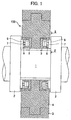
- FIG. 1 is an axial cross section illustrating the structure of a tilting-pad thrust bearing according to Embodiment 1.
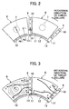
- FIG. 2 is a cross-sectional view in the direction of arrows II of FIG. 1 , illustrating the structure of pads according to Embodiment 1 (only two pads and only two oil pipes are shown for the sake of convenience).
- FIG. 3 illustrates the pressure of oil films on the sliding surfaces of the pads and the flow of lubricating oil.
- a rotary shaft 1 is disposed so as to extend horizontally (i.e., in the left and right direction of FIG. 1 ).
- the rotary shaft 1 has a pair of thrust collars 2 fixed to its outer circumference; thus, the rotary shaft 1 and the thrust collars 2 rotate together.
- the tilting-pad thrust bearing, designated by 100, receives the axial load of the rotary shaft 1 via the thrust collars 2.
- the thrust bearing 100 includes the following components: a substantially ring-shaped bearing housing 4 fixed to a pedestal 3; two substantially ring-shaped bearing bases 5, one of the bases 5 being internally fixed on one side of the housing 4 in terms of the axial direction (on the right side of FIG. 1 ), the other being internally fixed on the other side of the housing 4 (on the left side of FIG. 1 ); and multiple pads 6.
- eight pads 6 are arranged along the circumference of one of the bases 5 (i.e., on the outer circumferential side of the rotary shaft 1) so as to face one of the thrust collars 2.
- each of the pads 6 is arranged along the circumference of the other base 5 (i.e., on the outer circumferential side of the rotary shaft 1) so as to face the other thrust collar 2.
- Each of the pads 6 has a pivot 7 attached to its back side, and the pivot 7 is in contact with a pivot base 8.
- each of the pads 6 is supported in a swayable manner.
- oil pipes 9 are disposed in spaces between the pads 6.
- Each of the oil pipes 9 has multiple (three in the present embodiment) oil inlets 10 (i.e., nozzle orifices) arranged at intervals in a radial direction of the rotary shaft 1.
- each of the oil pipes 9 is disposed at a radially outward position so as not to interfere with a leading end projection 11 located at the radially inward leading end of the pad 6.
- the outermost oil inlet 10 is located at a radially outer position than the width-directional center L of the pad 6 or the center O of the swaying motion of the pad 6 (i.e., the center of the pivot 7).
- the innermost oil inlet 10 is located at a radially inner position than the width-directional center L or the swaying motion center O of the pad 6 (in other words, R1 ⁇ Ra ⁇ Rb as in FIG. 2 ).
- All the oil pipes 9 are connected to a pump (not illustrated) via oil passageways (not illustrated) formed within the bearing housing 4.
- the pump pressurizes lubricating oil, which is ejected through the oil inlets 10 of the oil pipes 9 toward the thrust collars 2. While the thrust collars 2 rotate, the oil enters spaces between the thrust collars 2 and the sliding surfaces of the pads 6 (i.e., the surfaces facing the thrust collars 2). This causes the pads 6 to sway, and the spaces between the sliding surfaces of the pads 6 and the thrust collars 2 become gradually smaller in the rotational direction of the thrust collars 2. Thus, dynamic pressure is generated due to the wedge effect, producing oil films.
- the lubricating oil supplied to the sliding surfaces of the pads 6 from the oil inlets 10 of the oil pipes 9 tends to partially drift away toward the outer and inner circumferential sides of the pads 6 due to the foregoing distribution of the oil film pressure.
- each of the pads 6 has an outflow guide groove 12.
- the outflow guide groove 12 is formed near the inner circumferential edge of the sliding surface of the pad 6 (i.e., at a position closer to the inner circumferential edge than the width-directional center L) such that it extends in a circumferential direction.
- the outflow guide groove 12 is open to the sliding surface and the trailing end surface of the pad 6.
- Each of the pads 6 also has an inflow guide groove 13 separated from the outflow guide groove 12.
- the inflow guide groove 13 is formed at the leading end projection 11 of the pad 6 (i.e., at the leading end section of the sliding surface of the pad 6) such that it is located at a radially inner position than the oil inlets 10 of the oil pipe 9.
- the inflow guide groove 13 is open to the leading end surface of the pad 6 so as to form an opening wide enough to include the same radial position as that of the opening of the outflow guide groove 12 on the trailing end surface of the pad 6.
- the inflow guide groove 13 is also open to the sliding surface of the pad 6 so as to form an opening wide enough to cover a radially outer area than the radial position of the outflow guide groove 12 on the sliding surface of the pad 6.
- the arrows a, b, c, and d of FIG. 3 represent the resultant oil flow.
- part of the oil supplied to the sliding surface of a pad 6 drifts toward the outer circumferential side of the pad 6 and flows out from the outer circumferential edge of the pad 6.
- part of the oil supplied to the sliding surface of a pad 6 slightly drifts toward the outer circumferential side of the pad 6 but flows out from the trailing end of the pad 6.
- part of the oil supplied to the sliding surface of a pad 6 slightly drifts toward the inner circumferential side of the pad 6 but flows out from the trailing end of the pad 6.
- part of the oil supplied to the sliding surface of a pad 6 drifts toward the inner circumferential side of the pad 6 but flows out from the trailing end of the pad 6 through the outflow guide groove 12.
- the oil flowing out through the outflow guide groove 12 has a relatively low temperature.
- the oil flowing out from the outflow guide groove 12 of an upstream pad 6 flows through the inflow guide groove 13 of a next downstream pad 6, reaching the sliding surface of that downstream pad 6.
- FIG. 4 is a graph illustrating the amount of oil supply according to related art (i.e., without the outflow guide groove 12 and the inflow guide groove 13).
- FIG. 5 is a graph illustrating the amount of oil supply according to Embodiment 1.
- the oil supplied to the sliding surface of a pad flows out not only from the trailing end of the pad but also from the outer and inner circumferential ends of the pad.
- the oil flowing out from the trailing end is partially supplied to a next downstream pad as a carry-over, and the rest is drained out of the bearing.
- the hatched area of FIG. 4 represents the amount of the carry-over while the non-hatched area above it represents the amount Qt of oil drained from the trailing end.
- the oil flowing out from the outer circumferential end is drained out of the bearing, and this amount is presented by the drained oil amount Qo.
- the oil flowing out from the inner circumferential end is also drained out of the bearing, and this amount is represented by the drained oil amount Qi (typically Qi ⁇ Qo).
- Qi typically Qi ⁇ Qo
- the total amount of oil drained from a pad is (Qt + Qo + Qi), which means that the same amount of oil, (Qt + Qo + Qi), needs to be supplied for the pad.
- the outflow guide groove 12 prevents the oil from flowing out from the inner circumferential end of the pad 6 and directs the oil toward the trailing end of the pad 6 (i.e., toward the leading end of the next downstream pad 6).
- the inflow guide groove 13 of the downstream pad 6 allows the oil flowing out from the outflow guide groove 12 of the upstream pad 6, which has a relatively low temperature, to be supplied onto the sliding surface of the downstream pad 6.
- the amount Qi of oil drained from the inner circumferential end of each pad 6 is substantially zero.
- the amount of oil supply needed for a pad can be reduced to (Qt + Qo).
- FIG. 6 illustrates the structure of pads according to Embodiment 2.
- the same components as used in Embodiment 1 are assigned the same reference numerals and will not be discussed further in detail.
- each oil pipe 9A is disposed at a radially inward position so as not to interfere with a leading end projection 14 located at the radially outward leading end of a pad 6A.
- the innermost oil inlet 10 of the oil pipe 9A is located at a radially inner position than the width-directional center L or the swaying motion center 0 of a pad 6A.
- the outermost oil inlet 10 is located at a radially outer position than the width-directional center L or the swaying motion center O of a pad 6A (in other words, Ra ⁇ Rb ⁇ R2 as in FIG. 6 ).
- Each pad 6A has an outflow guide groove 15.
- the outflow guide groove 15 is formed near the outer circumferential edge of the sliding surface of the pad 6A (i.e., at a position closer to the outer circumferential edge than the width-directional center L) such that it extends in a circumferential direction.
- the outflow guide groove 15 is open to the sliding surface and the trailing end surface of the pad 6A.
- Each pad 6A also has an inflow guide groove 16 separated from the outflow guide groove 15.
- the inflow guide groove 16 is formed at the leading end projection 14 of the pad 6A (i.e., at the leading end section of the sliding surface of the pad 6A) such that it is located at a radially outer position than the oil inlets 10 of the oil pipe 9A.
- the inflow guide groove 16 is open to the leading end surface of the pad 6A so as to form an opening wide enough to include the same radial position as that of the opening of the outflow guide groove 15 on the trailing end surface of the pad 6A.
- the inflow guide groove 16 is also open to the sliding surface of the pad 6A so as to form an opening wide enough to cover a radially inner area than the radial position of the outflow guide groove 15 on the sliding surface of the pad 6A.
- the outflow guide groove 15 prevents the oil from flowing out from the outer circumferential end of the pad 6A and directs the oil toward the trailing end of the pad 6A (i.e., toward the leading end of the next downstream pad 6A).
- the inflow guide groove 16 of the downstream pad 6A allows the oil flowing out from the outflow guide groove 15 of the upstream pad 6A, which has a relatively low temperature, to be supplied onto the sliding surface of the downstream pad 6A.
- the amount Qo of oil drained from the outer circumferential end of each pad 6A is substantially zero. As a result, the amount of oil supply needed for a pad can be reduced to (Qt + Qi).
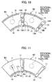
- FIG. 7 illustrates the structure of pads according to Embodiment 3.
- the same components as used in Embodiments 1 and 2 are assigned the same reference numerals and will not be discussed further in detail.
- each oil pipe 9B is disposed between two leading end projections 11 and 14 of a pad 6B so as not to interfere with the projections.
- the outer oil inlet 10 of the oil pipe 9B is located at a radially outer position than the width-directional center or the swaying motion center of a pad 6B.
- the inner oil inlet 10 is located at a radially inner position than the width-directional center or the swaying motion center of a pad 6B.
- Each pad 6B has an outflow guide groove 12.
- the outflow guide groove 12 is formed near the inner circumferential edge of the sliding surface of the pad 6B such that it extends in a circumferential direction.
- the outflow guide groove 12 is open to the sliding surface and the trailing end surface of the pad 6B.
- Each pad 6B also has an inflow guide groove 13 separated from the outflow guide groove 12.
- the inflow guide groove 13 is formed at the leading end projection 11 of the pad 6B such that it is located at a radially inner position than the oil inlets 10 of the oil pipe 9B.
- the inflow guide groove 13 is open to the leading end surface of the pad 6B so as to form an opening wide enough to include the same radial position as that of the opening of the outflow guide groove 12 on the trailing end surface of the pad 6B.
- the inflow guide groove 13 is also open to the sliding surface of the pad 6B so as to form an opening wide enough to cover a radially outer area than the radial position of the outflow guide groove 12 on the sliding surface of the pad 6B.
- Each pad 6B further has an outflow guide groove 15.
- the outflow guide groove 15 is formed near the outer circumferential edge of the sliding surface of the pad 6B such that it extends in a circumferential direction.
- the outflow guide groove 15 is open to the sliding surface and the trailing end surface of the pad 6B.
- Each pad 6B still further has an inflow guide groove 16 separated from the outflow guide groove 15.
- the inflow guide groove 16 is formed at the leading end projection 14 of the pad 6B such that it is located at a radially outer position than the oil inlets 10 of the oil pipe 9B.
- the inflow guide groove 16 is open to the leading end surface of the pad 6B so as to form an opening wide enough to include the same radial position as that of the opening of the outflow guide groove 15 on the trailing end surface of the pad 6B.
- the inflow guide groove 16 is also open to the sliding surface of the pad 6B so as to form an opening wide enough to cover a radially inner area than the radial position of the outflow guide groove 15 on the sliding surface of the pad 6B.
- the outflow guide grooves 12 and 15 prevent the oil from flowing out from the inner and outer circumferential ends of the pad 6B and direct the oil toward the trailing end of the pad 6B (i.e., toward the leading end of the next downstream pad 6B).
- the inflow guide grooves 13 and 16 of the downstream pad 6B allow the oil flowing out from the outflow guide grooves 12 and 15 of the upstream pad 6B, which has a relatively low temperature, to be supplied onto the sliding surface of the downstream pad 6B.
- the amount Qi of oil drained from the inner circumferential end of each pad 6B and the amount Qo of oil drained from the outer circumferential end of each pad 6B are both substantially zero. As a result, the amount of oil supply needed for a pad can be reduced to Qt.
- each inflow guide groove 13, as illustrated is formed such that its radially inner wall surface extends in a circumferential direction.
- each inflow guide groove 16, as illustrated is formed such that its radially outer wall surface extends in a circumferential direction.
- the present invention is not limited to such cases but can be modified without departing from the scope and spirit of the invention.
- the inflow guide groove 13A of each pad can be formed such that its radially inner wall surface is tilted radially outward as going in a downstream circumferential direction.
- the inflow guide groove 16A of each pad can be formed such that its radially outer wall surface is tilted radially inward as going in a downstream circumferential direction.
- Embodiments 1 to 3 illustrate the case where oil pipes are disposed in spaces between pads
- the invention is not limited thereto but can be modified without departing the scope and spirit of the invention.
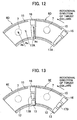
- an oil inlet 17 can instead be formed such that it is located radially outward near the front edge of the sliding surface of each pad 6C.
- the radially inner side wall of the oil inlet 17 is located at a radially inner position than the width-directional center L or the swaying motion center O of the pad 6C (i.e., R3 ⁇ Ra ⁇ Rb as in FIG. 11 ).
- an inflow guide groove 13 can be formed at the front edge of the sliding surface of each pad 6C such that it is located at a radially inner position than the oil inlet 17.
- an oil inlet 17A can instead be formed such that it is located radially inward near the front edge of the sliding surface of each pad 6D.
- the radially outer side wall of the oil inlet 17A is located at a radially outer position than the width-directional center L or the swaying motion center O of the pad 6D (i.e., Ra ⁇ Rb ⁇ R4 as in FIG. 12 ).
- an inflow guide groove 16 can be formed at the front edge of the sliding surface of each pad 6C such that it is located at a radially outer position than the oil inlet 17A.
- an oil inlet 17B can instead be formed such that it is located radially centrally near the front edge of the sliding surface of each pad 6E.
- the radially inner side wall of the oil inlet 17B is located at a radially inner position than the width-directional center or the swaying motion center of the pad 6E while the radially outer side wall of the oil inlet 17B is located at a radially outer position than the width-directional center or the swaying motion center of the pad 6E.
- an inflow guide groove 13 can be formed at the front edge of the sliding surface of each pad 6E such that it is located at a radially inner position than the oil inlet 17B while an inflow guide groove 16 can be formed at the front edge of the sliding surface of each pad 6E such that it is located at a radially outer position than the oil inlet 17B.
- FIG. 14 illustrates the structure of a steam turbine having the tilting-pad thrust bearing 100.
- the steam turbine includes a highpressure turbine 20, a medium-pressure turbine 21, and a low-pressure turbine 22 to receive different steam pressures. These turbines 20, 21, and 22 are connected to a generator 23 via a rotary shaft 1.
- the steam turbine also includes multiple journal bearings 24 for receiving the radial load of the rotary shaft 1 and the thrust bearing 100 for receiving the axial load of the rotary shaft 1.
- auxiliary equipment and related components for oil supply can be reduced in size since the amount of oil supply to the thrust bearing 100 is smaller. Accordingly, the steam turbine can also be made compact.
- the rotary shaft 1 extends horizontally, and the tilting-pad thrust bearing 100 receives the axial load of the rotary shaft 1 via a pair of thrust collars 2.
- the present invention is not limited to such a case but can be modified without departing from the scope and spirit of the invention.
- the rotary shaft 1 can instead extend vertically, and the tilting-pad thrust bearing 100 can receive the axial load of the rotary shaft 1 via one thrust collar.
- the same advantageous effects as those of the above example can be obtained.
Landscapes
- Engineering & Computer Science (AREA)
- General Engineering & Computer Science (AREA)
- Mechanical Engineering (AREA)
- Chemical & Material Sciences (AREA)
- Oil, Petroleum & Natural Gas (AREA)
- Physics & Mathematics (AREA)
- Fluid Mechanics (AREA)
- Sliding-Contact Bearings (AREA)
Applications Claiming Priority (1)
| Application Number | Priority Date | Filing Date | Title |
|---|---|---|---|
| JP2013232028A JP6184299B2 (ja) | 2013-11-08 | 2013-11-08 | ティルティングパッド式スラスト軸受及びこれを備えた回転機械 |
Publications (2)
| Publication Number | Publication Date |
|---|---|
| EP2878837A1 EP2878837A1 (en) | 2015-06-03 |
| EP2878837B1 true EP2878837B1 (en) | 2016-04-27 |
Family
ID=51903809
Family Applications (1)
| Application Number | Title | Priority Date | Filing Date |
|---|---|---|---|
| EP14192078.5A Not-in-force EP2878837B1 (en) | 2013-11-08 | 2014-11-06 | Tilting-pad thrust bearing and rotary machine having the same |
Country Status (3)
| Country | Link |
|---|---|
| US (1) | US9670957B2 (enExample) |
| EP (1) | EP2878837B1 (enExample) |
| JP (1) | JP6184299B2 (enExample) |
Families Citing this family (12)
| Publication number | Priority date | Publication date | Assignee | Title |
|---|---|---|---|---|
| JP2018105467A (ja) | 2016-12-28 | 2018-07-05 | 株式会社日立製作所 | ティルティングパッド型ジャーナル軸受 |
| JP6990977B2 (ja) | 2017-03-07 | 2022-01-12 | 大同メタル工業株式会社 | 摺動部材 |
| DE102017116786A1 (de) * | 2017-07-25 | 2019-01-31 | Zollern Bhw Gleitlager Gmbh & Co. Kg | Lageranordnung zum Lagern einer Welle eines Getriebes |
| CN107642542B (zh) * | 2017-09-25 | 2024-01-09 | 台州七八一六船舶工业有限公司 | 一种高速止推滑动轴承 |
| BR112020009947B1 (pt) * | 2018-03-15 | 2024-02-20 | Sulzer Management Ag | Almofada para um conjunto de rolamentos de empuxo de almofada oscilante e conjunto de rolamentos de empuxo e bomba centrífuga |
| JP7136734B2 (ja) | 2019-03-28 | 2022-09-13 | 大同メタル工業株式会社 | 摺動部材 |
| CN110552745A (zh) * | 2019-09-23 | 2019-12-10 | 云南锡业股份有限公司铜业分公司 | 一种汽轮机推力瓦组件及延长推力瓦使用寿命的方法 |
| JP7335178B2 (ja) * | 2020-02-06 | 2023-08-29 | 大同メタル工業株式会社 | 摺動部材 |
| JP7335179B2 (ja) * | 2020-02-06 | 2023-08-29 | 大同メタル工業株式会社 | 摺動部材 |
| CN113775642B (zh) * | 2021-09-15 | 2023-08-22 | 上海涟屹轴承科技有限公司 | 推力轴承及转动轴 |
| US12135057B2 (en) * | 2022-08-31 | 2024-11-05 | Elliott Company | Tilt pad journal bearing with lubrication arrangement |
| CN116241553B (zh) * | 2023-04-06 | 2024-08-06 | 浙江彰贵轴承科技有限公司 | 一种支点偏移量可调节的可倾瓦推力滑动轴承 |
Family Cites Families (15)
| Publication number | Priority date | Publication date | Assignee | Title |
|---|---|---|---|---|
| JPS4967063A (enExample) * | 1972-11-10 | 1974-06-28 | ||
| US4077682A (en) * | 1976-08-24 | 1978-03-07 | Waukesha Bearings Corporation | Large thrust bearing with lubrication in the spaces between pads |
| DE3117746A1 (de) | 1981-05-05 | 1982-12-09 | Krupp Polysius Ag, 4720 Beckum | Hydrodynamisches radial-gleitlager |
| JPS594817U (ja) * | 1982-07-01 | 1984-01-12 | 株式会社東芝 | パツド型ジヤ−ナル軸受装置 |
| JPS5996422U (ja) | 1982-12-20 | 1984-06-30 | 株式会社東芝 | パツド形スラスト軸受装置 |
| JPS6295455U (enExample) * | 1985-12-02 | 1987-06-18 | ||
| JPH07113422A (ja) * | 1993-10-15 | 1995-05-02 | Mitsubishi Heavy Ind Ltd | ティルティングパッドスラスト軸受 |
| JPH08145052A (ja) * | 1994-11-24 | 1996-06-04 | Mitsubishi Heavy Ind Ltd | 動圧軸受 |
| US5702186A (en) * | 1996-08-02 | 1997-12-30 | Westinghouse Electric Corporation | Journal bearing with leading edge groove vent |
| US6499883B2 (en) | 1997-03-31 | 2002-12-31 | Whm Holding Corporation | Tilting pad for bearings |
| JP2000356222A (ja) * | 1999-06-14 | 2000-12-26 | Tokyo Electric Power Co Inc:The | スラスト軸受装置 |
| JP2012117608A (ja) * | 2010-11-30 | 2012-06-21 | Mitsubishi Heavy Ind Ltd | スラスト軸受装置 |
| US9739310B2 (en) * | 2011-09-21 | 2017-08-22 | Dresser-Rand Company | Tilt pad bearing with through-pivot lubrication |
| JP5860172B2 (ja) * | 2012-12-28 | 2016-02-16 | 株式会社日立製作所 | 組合せ軸受装置 |
| JP2015007463A (ja) * | 2013-06-26 | 2015-01-15 | 三菱日立パワーシステムズ株式会社 | ティルティングパッド軸受 |
-
2013
- 2013-11-08 JP JP2013232028A patent/JP6184299B2/ja not_active Expired - Fee Related
-
2014
- 2014-11-05 US US14/533,468 patent/US9670957B2/en not_active Expired - Fee Related
- 2014-11-06 EP EP14192078.5A patent/EP2878837B1/en not_active Not-in-force
Also Published As
| Publication number | Publication date |
|---|---|
| JP2015094373A (ja) | 2015-05-18 |
| US20150132105A1 (en) | 2015-05-14 |
| JP6184299B2 (ja) | 2017-08-23 |
| EP2878837A1 (en) | 2015-06-03 |
| US9670957B2 (en) | 2017-06-06 |
Similar Documents
| Publication | Publication Date | Title |
|---|---|---|
| EP2878837B1 (en) | Tilting-pad thrust bearing and rotary machine having the same | |
| JP6412788B2 (ja) | ティルティングパッド軸受 | |
| CN103842667B (zh) | 增压器的止推轴承装置 | |
| JP5416859B2 (ja) | ティルティングパッド型ジャーナル軸受及びこれを備えた回転機械 | |
| US20060186671A1 (en) | Submerged turbine generator | |
| US10161446B2 (en) | Plain self-centering bearing | |
| JPWO2016084937A1 (ja) | ジャーナル軸受、回転機械 | |
| JP6296157B2 (ja) | 軸受構造、および、過給機 | |
| CN103470319A (zh) | 用于涡轮的轴颈轴承垫 | |
| JP2006510855A (ja) | 耐荷重が増大した軸方向スラスト軸受用のコンプライアントサポート | |
| US9377051B2 (en) | Duplex bearing device | |
| EP3163102A1 (en) | Thrust bearing and rotating machine | |
| CN111042923B (zh) | 一种转子系统及微型燃气轮机发电机组 | |
| CN108884861B (zh) | 轴承装置及旋转机械 | |
| JP5569114B2 (ja) | 過給機 | |
| JP2008151239A (ja) | ティルティングパッド型軸受 | |
| JP6403594B2 (ja) | ジャーナル軸受及び回転機械 | |
| JP6403593B2 (ja) | ジャーナル軸受及び回転機械 | |
| JP5978946B2 (ja) | 過給機 | |
| KR20230145022A (ko) | 유체 베어링 | |
| JP6399698B2 (ja) | 軸受装置、回転機械 | |
| CN104583563B (zh) | 包括转子和壳体的流体机械 | |
| JP2014167281A (ja) | ガスタービン |
Legal Events
| Date | Code | Title | Description |
|---|---|---|---|
| PUAI | Public reference made under article 153(3) epc to a published international application that has entered the european phase |
Free format text: ORIGINAL CODE: 0009012 |
|
| 17P | Request for examination filed |
Effective date: 20141219 |
|
| AK | Designated contracting states |
Kind code of ref document: A1 Designated state(s): AL AT BE BG CH CY CZ DE DK EE ES FI FR GB GR HR HU IE IS IT LI LT LU LV MC MK MT NL NO PL PT RO RS SE SI SK SM TR |
|
| AX | Request for extension of the european patent |
Extension state: BA ME |
|
| GRAP | Despatch of communication of intention to grant a patent |
Free format text: ORIGINAL CODE: EPIDOSNIGR1 |
|
| RIC1 | Information provided on ipc code assigned before grant |
Ipc: F16C 17/03 20060101AFI20150923BHEP Ipc: F16C 33/10 20060101ALI20150923BHEP Ipc: F16C 17/06 20060101ALI20150923BHEP |
|
| INTG | Intention to grant announced |
Effective date: 20151029 |
|
| GRAS | Grant fee paid |
Free format text: ORIGINAL CODE: EPIDOSNIGR3 |
|
| GRAA | (expected) grant |
Free format text: ORIGINAL CODE: 0009210 |
|
| AK | Designated contracting states |
Kind code of ref document: B1 Designated state(s): AL AT BE BG CH CY CZ DE DK EE ES FI FR GB GR HR HU IE IS IT LI LT LU LV MC MK MT NL NO PL PT RO RS SE SI SK SM TR |
|
| REG | Reference to a national code |
Ref country code: GB Ref legal event code: FG4D |
|
| REG | Reference to a national code |
Ref country code: CH Ref legal event code: EP |
|
| REG | Reference to a national code |
Ref country code: AT Ref legal event code: REF Ref document number: 795152 Country of ref document: AT Kind code of ref document: T Effective date: 20160515 |
|
| REG | Reference to a national code |
Ref country code: IE Ref legal event code: FG4D |
|
| REG | Reference to a national code |
Ref country code: DE Ref legal event code: R096 Ref document number: 602014001719 Country of ref document: DE |
|
| REG | Reference to a national code |
Ref country code: LT Ref legal event code: MG4D |
|
| REG | Reference to a national code |
Ref country code: NL Ref legal event code: MP Effective date: 20160427 |
|
| REG | Reference to a national code |
Ref country code: AT Ref legal event code: MK05 Ref document number: 795152 Country of ref document: AT Kind code of ref document: T Effective date: 20160427 |
|
| PG25 | Lapsed in a contracting state [announced via postgrant information from national office to epo] |
Ref country code: NL Free format text: LAPSE BECAUSE OF FAILURE TO SUBMIT A TRANSLATION OF THE DESCRIPTION OR TO PAY THE FEE WITHIN THE PRESCRIBED TIME-LIMIT Effective date: 20160427 |
|
| PG25 | Lapsed in a contracting state [announced via postgrant information from national office to epo] |
Ref country code: FI Free format text: LAPSE BECAUSE OF FAILURE TO SUBMIT A TRANSLATION OF THE DESCRIPTION OR TO PAY THE FEE WITHIN THE PRESCRIBED TIME-LIMIT Effective date: 20160427 Ref country code: NO Free format text: LAPSE BECAUSE OF FAILURE TO SUBMIT A TRANSLATION OF THE DESCRIPTION OR TO PAY THE FEE WITHIN THE PRESCRIBED TIME-LIMIT Effective date: 20160727 Ref country code: LT Free format text: LAPSE BECAUSE OF FAILURE TO SUBMIT A TRANSLATION OF THE DESCRIPTION OR TO PAY THE FEE WITHIN THE PRESCRIBED TIME-LIMIT Effective date: 20160427 Ref country code: PL Free format text: LAPSE BECAUSE OF FAILURE TO SUBMIT A TRANSLATION OF THE DESCRIPTION OR TO PAY THE FEE WITHIN THE PRESCRIBED TIME-LIMIT Effective date: 20160427 |
|
| PG25 | Lapsed in a contracting state [announced via postgrant information from national office to epo] |
Ref country code: SE Free format text: LAPSE BECAUSE OF FAILURE TO SUBMIT A TRANSLATION OF THE DESCRIPTION OR TO PAY THE FEE WITHIN THE PRESCRIBED TIME-LIMIT Effective date: 20160427 Ref country code: PT Free format text: LAPSE BECAUSE OF FAILURE TO SUBMIT A TRANSLATION OF THE DESCRIPTION OR TO PAY THE FEE WITHIN THE PRESCRIBED TIME-LIMIT Effective date: 20160829 Ref country code: GR Free format text: LAPSE BECAUSE OF FAILURE TO SUBMIT A TRANSLATION OF THE DESCRIPTION OR TO PAY THE FEE WITHIN THE PRESCRIBED TIME-LIMIT Effective date: 20160728 Ref country code: RS Free format text: LAPSE BECAUSE OF FAILURE TO SUBMIT A TRANSLATION OF THE DESCRIPTION OR TO PAY THE FEE WITHIN THE PRESCRIBED TIME-LIMIT Effective date: 20160427 Ref country code: AT Free format text: LAPSE BECAUSE OF FAILURE TO SUBMIT A TRANSLATION OF THE DESCRIPTION OR TO PAY THE FEE WITHIN THE PRESCRIBED TIME-LIMIT Effective date: 20160427 Ref country code: ES Free format text: LAPSE BECAUSE OF FAILURE TO SUBMIT A TRANSLATION OF THE DESCRIPTION OR TO PAY THE FEE WITHIN THE PRESCRIBED TIME-LIMIT Effective date: 20160427 Ref country code: HR Free format text: LAPSE BECAUSE OF FAILURE TO SUBMIT A TRANSLATION OF THE DESCRIPTION OR TO PAY THE FEE WITHIN THE PRESCRIBED TIME-LIMIT Effective date: 20160427 Ref country code: LV Free format text: LAPSE BECAUSE OF FAILURE TO SUBMIT A TRANSLATION OF THE DESCRIPTION OR TO PAY THE FEE WITHIN THE PRESCRIBED TIME-LIMIT Effective date: 20160427 |
|
| PG25 | Lapsed in a contracting state [announced via postgrant information from national office to epo] |
Ref country code: BE Free format text: LAPSE BECAUSE OF FAILURE TO SUBMIT A TRANSLATION OF THE DESCRIPTION OR TO PAY THE FEE WITHIN THE PRESCRIBED TIME-LIMIT Effective date: 20160427 Ref country code: IT Free format text: LAPSE BECAUSE OF FAILURE TO SUBMIT A TRANSLATION OF THE DESCRIPTION OR TO PAY THE FEE WITHIN THE PRESCRIBED TIME-LIMIT Effective date: 20160427 |
|
| REG | Reference to a national code |
Ref country code: DE Ref legal event code: R097 Ref document number: 602014001719 Country of ref document: DE |
|
| PG25 | Lapsed in a contracting state [announced via postgrant information from national office to epo] |
Ref country code: CZ Free format text: LAPSE BECAUSE OF FAILURE TO SUBMIT A TRANSLATION OF THE DESCRIPTION OR TO PAY THE FEE WITHIN THE PRESCRIBED TIME-LIMIT Effective date: 20160427 Ref country code: EE Free format text: LAPSE BECAUSE OF FAILURE TO SUBMIT A TRANSLATION OF THE DESCRIPTION OR TO PAY THE FEE WITHIN THE PRESCRIBED TIME-LIMIT Effective date: 20160427 Ref country code: DK Free format text: LAPSE BECAUSE OF FAILURE TO SUBMIT A TRANSLATION OF THE DESCRIPTION OR TO PAY THE FEE WITHIN THE PRESCRIBED TIME-LIMIT Effective date: 20160427 Ref country code: RO Free format text: LAPSE BECAUSE OF FAILURE TO SUBMIT A TRANSLATION OF THE DESCRIPTION OR TO PAY THE FEE WITHIN THE PRESCRIBED TIME-LIMIT Effective date: 20160427 Ref country code: SK Free format text: LAPSE BECAUSE OF FAILURE TO SUBMIT A TRANSLATION OF THE DESCRIPTION OR TO PAY THE FEE WITHIN THE PRESCRIBED TIME-LIMIT Effective date: 20160427 |
|
| PG25 | Lapsed in a contracting state [announced via postgrant information from national office to epo] |
Ref country code: SM Free format text: LAPSE BECAUSE OF FAILURE TO SUBMIT A TRANSLATION OF THE DESCRIPTION OR TO PAY THE FEE WITHIN THE PRESCRIBED TIME-LIMIT Effective date: 20160427 |
|
| PLBE | No opposition filed within time limit |
Free format text: ORIGINAL CODE: 0009261 |
|
| STAA | Information on the status of an ep patent application or granted ep patent |
Free format text: STATUS: NO OPPOSITION FILED WITHIN TIME LIMIT |
|
| 26N | No opposition filed |
Effective date: 20170130 |
|
| PG25 | Lapsed in a contracting state [announced via postgrant information from national office to epo] |
Ref country code: SI Free format text: LAPSE BECAUSE OF FAILURE TO SUBMIT A TRANSLATION OF THE DESCRIPTION OR TO PAY THE FEE WITHIN THE PRESCRIBED TIME-LIMIT Effective date: 20160427 |
|
| REG | Reference to a national code |
Ref country code: IE Ref legal event code: MM4A |
|
| REG | Reference to a national code |
Ref country code: FR Ref legal event code: ST Effective date: 20170731 |
|
| PG25 | Lapsed in a contracting state [announced via postgrant information from national office to epo] |
Ref country code: LU Free format text: LAPSE BECAUSE OF NON-PAYMENT OF DUE FEES Effective date: 20161130 |
|
| PG25 | Lapsed in a contracting state [announced via postgrant information from national office to epo] |
Ref country code: FR Free format text: LAPSE BECAUSE OF NON-PAYMENT OF DUE FEES Effective date: 20161130 |
|
| PG25 | Lapsed in a contracting state [announced via postgrant information from national office to epo] |
Ref country code: IE Free format text: LAPSE BECAUSE OF NON-PAYMENT OF DUE FEES Effective date: 20161106 |
|
| PG25 | Lapsed in a contracting state [announced via postgrant information from national office to epo] |
Ref country code: HU Free format text: LAPSE BECAUSE OF FAILURE TO SUBMIT A TRANSLATION OF THE DESCRIPTION OR TO PAY THE FEE WITHIN THE PRESCRIBED TIME-LIMIT; INVALID AB INITIO Effective date: 20141106 |
|
| PG25 | Lapsed in a contracting state [announced via postgrant information from national office to epo] |
Ref country code: MK Free format text: LAPSE BECAUSE OF FAILURE TO SUBMIT A TRANSLATION OF THE DESCRIPTION OR TO PAY THE FEE WITHIN THE PRESCRIBED TIME-LIMIT Effective date: 20160427 Ref country code: CY Free format text: LAPSE BECAUSE OF FAILURE TO SUBMIT A TRANSLATION OF THE DESCRIPTION OR TO PAY THE FEE WITHIN THE PRESCRIBED TIME-LIMIT Effective date: 20160427 Ref country code: MC Free format text: LAPSE BECAUSE OF FAILURE TO SUBMIT A TRANSLATION OF THE DESCRIPTION OR TO PAY THE FEE WITHIN THE PRESCRIBED TIME-LIMIT Effective date: 20160427 Ref country code: IS Free format text: LAPSE BECAUSE OF FAILURE TO SUBMIT A TRANSLATION OF THE DESCRIPTION OR TO PAY THE FEE WITHIN THE PRESCRIBED TIME-LIMIT Effective date: 20160427 |
|
| PG25 | Lapsed in a contracting state [announced via postgrant information from national office to epo] |
Ref country code: LI Free format text: LAPSE BECAUSE OF NON-PAYMENT OF DUE FEES Effective date: 20171130 Ref country code: BG Free format text: LAPSE BECAUSE OF FAILURE TO SUBMIT A TRANSLATION OF THE DESCRIPTION OR TO PAY THE FEE WITHIN THE PRESCRIBED TIME-LIMIT Effective date: 20160427 Ref country code: CH Free format text: LAPSE BECAUSE OF NON-PAYMENT OF DUE FEES Effective date: 20171130 |
|
| PG25 | Lapsed in a contracting state [announced via postgrant information from national office to epo] |
Ref country code: MT Free format text: LAPSE BECAUSE OF NON-PAYMENT OF DUE FEES Effective date: 20161106 |
|
| PG25 | Lapsed in a contracting state [announced via postgrant information from national office to epo] |
Ref country code: TR Free format text: LAPSE BECAUSE OF FAILURE TO SUBMIT A TRANSLATION OF THE DESCRIPTION OR TO PAY THE FEE WITHIN THE PRESCRIBED TIME-LIMIT Effective date: 20160427 Ref country code: AL Free format text: LAPSE BECAUSE OF FAILURE TO SUBMIT A TRANSLATION OF THE DESCRIPTION OR TO PAY THE FEE WITHIN THE PRESCRIBED TIME-LIMIT Effective date: 20160427 |
|
| GBPC | Gb: european patent ceased through non-payment of renewal fee |
Effective date: 20181106 |
|
| PG25 | Lapsed in a contracting state [announced via postgrant information from national office to epo] |
Ref country code: GB Free format text: LAPSE BECAUSE OF NON-PAYMENT OF DUE FEES Effective date: 20181106 |
|
| REG | Reference to a national code |
Ref country code: DE Ref legal event code: R082 Ref document number: 602014001719 Country of ref document: DE Representative=s name: MERH-IP MATIAS ERNY REICHL HOFFMANN PATENTANWA, DE Ref country code: DE Ref legal event code: R081 Ref document number: 602014001719 Country of ref document: DE Owner name: MITSUBISHI POWER, LTD., JP Free format text: FORMER OWNER: MITSUBISHI HITACHI POWER SYSTEMS, LTD., YOKOHAMA, JP |
|
| PGFP | Annual fee paid to national office [announced via postgrant information from national office to epo] |
Ref country code: DE Payment date: 20210929 Year of fee payment: 8 |
|
| REG | Reference to a national code |
Ref country code: DE Ref legal event code: R119 Ref document number: 602014001719 Country of ref document: DE |
|
| PG25 | Lapsed in a contracting state [announced via postgrant information from national office to epo] |
Ref country code: DE Free format text: LAPSE BECAUSE OF NON-PAYMENT OF DUE FEES Effective date: 20230601 |