US9739310B2 - Tilt pad bearing with through-pivot lubrication - Google Patents

Tilt pad bearing with through-pivot lubrication Download PDF

Info

Publication number
US9739310B2
US9739310B2 US14/344,932 US201214344932A US9739310B2 US 9739310 B2 US9739310 B2 US 9739310B2 US 201214344932 A US201214344932 A US 201214344932A US 9739310 B2 US9739310 B2 US 9739310B2
Authority
US
United States
Prior art keywords
pad
pivot
support structure
channel
bearing
Prior art date
Legal status (The legal status is an assumption and is not a legal conclusion. Google has not performed a legal analysis and makes no representation as to the accuracy of the status listed.)
Active, expires
Application number
US14/344,932
Other versions
US20150159692A1 (en
Inventor
Herve Dourlens
Claude Lemetteil
Current Assignee (The listed assignees may be inaccurate. Google has not performed a legal analysis and makes no representation or warranty as to the accuracy of the list.)
Siemens Energy Inc
Original Assignee
Dresser Rand Co
Priority date (The priority date is an assumption and is not a legal conclusion. Google has not performed a legal analysis and makes no representation as to the accuracy of the date listed.)
Filing date
Publication date
Application filed by Dresser Rand Co filed Critical Dresser Rand Co
Priority to US14/344,932 priority Critical patent/US9739310B2/en
Assigned to DRESSER-RAND COMPANY reassignment DRESSER-RAND COMPANY ASSIGNMENT OF ASSIGNORS INTEREST (SEE DOCUMENT FOR DETAILS). Assignors: DOURLENS, HERVE, LEMETTEIL, CLAUDE
Publication of US20150159692A1 publication Critical patent/US20150159692A1/en
Application granted granted Critical
Publication of US9739310B2 publication Critical patent/US9739310B2/en
Assigned to SIEMENS ENERGY, INC. reassignment SIEMENS ENERGY, INC. MERGER (SEE DOCUMENT FOR DETAILS). Assignors: DRESSER-RAND COMPANY
Active legal-status Critical Current
Adjusted expiration legal-status Critical

Links

Images

Classifications

    • FMECHANICAL ENGINEERING; LIGHTING; HEATING; WEAPONS; BLASTING
    • F16ENGINEERING ELEMENTS AND UNITS; GENERAL MEASURES FOR PRODUCING AND MAINTAINING EFFECTIVE FUNCTIONING OF MACHINES OR INSTALLATIONS; THERMAL INSULATION IN GENERAL
    • F16CSHAFTS; FLEXIBLE SHAFTS; ELEMENTS OR CRANKSHAFT MECHANISMS; ROTARY BODIES OTHER THAN GEARING ELEMENTS; BEARINGS
    • F16C33/00Parts of bearings; Special methods for making bearings or parts thereof
    • F16C33/02Parts of sliding-contact bearings
    • FMECHANICAL ENGINEERING; LIGHTING; HEATING; WEAPONS; BLASTING
    • F16ENGINEERING ELEMENTS AND UNITS; GENERAL MEASURES FOR PRODUCING AND MAINTAINING EFFECTIVE FUNCTIONING OF MACHINES OR INSTALLATIONS; THERMAL INSULATION IN GENERAL
    • F16CSHAFTS; FLEXIBLE SHAFTS; ELEMENTS OR CRANKSHAFT MECHANISMS; ROTARY BODIES OTHER THAN GEARING ELEMENTS; BEARINGS
    • F16C17/00Sliding-contact bearings for exclusively rotary movement
    • F16C17/02Sliding-contact bearings for exclusively rotary movement for radial load only
    • F16C17/03Sliding-contact bearings for exclusively rotary movement for radial load only with tiltably-supported segments, e.g. Michell bearings
    • FMECHANICAL ENGINEERING; LIGHTING; HEATING; WEAPONS; BLASTING
    • F16ENGINEERING ELEMENTS AND UNITS; GENERAL MEASURES FOR PRODUCING AND MAINTAINING EFFECTIVE FUNCTIONING OF MACHINES OR INSTALLATIONS; THERMAL INSULATION IN GENERAL
    • F16CSHAFTS; FLEXIBLE SHAFTS; ELEMENTS OR CRANKSHAFT MECHANISMS; ROTARY BODIES OTHER THAN GEARING ELEMENTS; BEARINGS
    • F16C17/00Sliding-contact bearings for exclusively rotary movement
    • F16C17/04Sliding-contact bearings for exclusively rotary movement for axial load only
    • F16C17/06Sliding-contact bearings for exclusively rotary movement for axial load only with tiltably-supported segments, e.g. Michell bearings
    • FMECHANICAL ENGINEERING; LIGHTING; HEATING; WEAPONS; BLASTING
    • F16ENGINEERING ELEMENTS AND UNITS; GENERAL MEASURES FOR PRODUCING AND MAINTAINING EFFECTIVE FUNCTIONING OF MACHINES OR INSTALLATIONS; THERMAL INSULATION IN GENERAL
    • F16CSHAFTS; FLEXIBLE SHAFTS; ELEMENTS OR CRANKSHAFT MECHANISMS; ROTARY BODIES OTHER THAN GEARING ELEMENTS; BEARINGS
    • F16C33/00Parts of bearings; Special methods for making bearings or parts thereof
    • F16C33/02Parts of sliding-contact bearings
    • F16C33/04Brasses; Bushes; Linings
    • F16C33/06Sliding surface mainly made of metal
    • F16C33/10Construction relative to lubrication
    • F16C33/1025Construction relative to lubrication with liquid, e.g. oil, as lubricant
    • F16C33/106Details of distribution or circulation inside the bearings, e.g. details of the bearing surfaces to affect flow or pressure of the liquid
    • F16C33/1085Channels or passages to recirculate the liquid in the bearing

Definitions

  • Tilt pad bearings are used to support a rotating shaft within a turbomachine, such as a turbine or a compressor.
  • Tilt pad bearings include a bearing cage and one or more pads that are coupled to the bearing cage through a pivot.
  • the pads are adapted to contact and support the shaft, and the pivot enables the pads to move or “tilt” when supporting the shaft to prevent pad edge loading.
  • Lubricating fluid such as oil, is often injected between the shaft and the pads to reduce the friction, and the associated heat, between the two components.
  • Oil injectors are oftentimes positioned between adjacent pads. When positioned in this manner, however, the oil injectors restrain the circulation of lubricant behind the pads, thus limiting the desired cooling effect to this region of the pads.
  • other bearing designs include a small pipe that extends from the bearing cage through an edge of the pad and provides lubricant to the inner surface of the pad. The pipe, however, tends to reduce the ability of the pads to move freely on their pivots.
  • Embodiments of the disclosure may provide a tilt pad bearing including a support structure having first and second support structure surfaces.
  • a pivot may have first and second pivot surfaces, and the first pivot surface may be coupled to the second support structure surface.
  • a pad may have first and second pad surfaces, and the first pad surface may be coupled to the second pivot surface.
  • a path of fluid communication may extend from the first support structure surface, through the pivot, and to an opening in the second pad surface.
  • Embodiments of the disclosure may also provide a tilt pad bearing including a support structure having first and second support structure surfaces and a support structure channel extending between the first and second support structure surfaces.
  • a pivot may have first and second pivot surfaces, and the first pivot surface may be coupled to the second support structure surface.
  • the pivot may define a pivot channel that extends between the first and second pivot surfaces and is in fluid communication with the support structure channel.
  • a pad may have first and second pad surfaces, and the first pad surface may be coupled to the second pivot surface.
  • the pad may define a pad channel that extends between the first and second pad surfaces and is in fluid communication with the pivot channel.
  • Embodiments of the disclosure may further provide a method of lubricating a tilt pad bearing.
  • the method may include introducing a lubricant to a support structure channel defined by a support structure.
  • the method may also include flowing the lubricant from the support structure channel into a pivot channel defined by a pivot and fluidly coupled to the support structure channel, and the pivot may be coupled to the support structure.
  • the method may further include flowing the lubricant from the pivot channel into a pad channel defined by a pad and fluidly coupled to the pivot channel.
  • the pad may be coupled to the pivot such that the pad is adapted to tilt with respect to the support structure.
  • FIG. 1 illustrates a perspective view of a portion of a tilt pad journal bearing, according to one or more embodiments disclosed.
  • FIG. 2 illustrates a cross-sectional view of the tilt pad journal bearing of FIG. 1 having a bearing cage disposed circumferentially thereabout, according to one or more embodiments disclosed.
  • FIG. 3 illustrates a perspective view of a portion of a tilt pad thrust bearing, according to one or more embodiments disclosed.
  • FIG. 4 illustrates a top view of a portion of the tilt pad thrust bearing of FIG. 3 , according to one or more embodiments disclosed.
  • FIG. 5 illustrates a cross-sectional view of the tilt pad thrust bearing depicted in FIG. 4 taken along line V-V, according to one or more embodiments disclosed.
  • FIG. 6 is a flowchart of a method for lubricating a tilt pad bearing, according to one or more embodiments disclosed.
  • first and second features are formed in direct contact
  • additional features may be formed interposing the first and second features, such that the first and second features may not be in direct contact.
  • exemplary embodiments presented below may be combined in any combination of ways, i.e., any element from one exemplary embodiment may be used in any other exemplary embodiment, without departing from the scope of the disclosure.
  • FIG. 1 illustrates a perspective view of a portion of a tilt pad journal bearing 100
  • FIG. 2 illustrates a cross-sectional view of the tilt pad journal bearing 100 having a bearing cage 102 disposed circumferentially thereabout, according to one or more embodiments described.
  • the journal bearing 100 may be adapted to engage and support a rotatable shaft (not shown) in a turbomachine. At least one journal bearing 100 may be disposed proximate each axial end of the shaft and adapted to support a radial load thereof.
  • the bearing 100 may be used in a variety of turbomachine applications, such as turbines, compressors, pumps, etc.
  • the journal bearing 100 may include a support structure 102 ( FIG. 2 ), or annular bearing cage, having a first, radially-outer surface 104 and a second, radially-inner surface 106 .
  • a bearing housing (not shown) may be disposed radially-outward from the outer surface 104 of the bearing cage 102 , thereby maintaining the support structure aligned.
  • One or more pivots 110 (five are shown) may be disposed radially-inward from the bearing cage 102 .
  • Each pivot 110 may have a first, outer surface 112 and a second, inner surface 114 .
  • the outer surface 112 of each pivot 110 may be coupled to and/or engaged with the inner surface 106 of the bearing cage 102 .
  • the outer surface 112 may be generally flat, and the inner surface 114 may be arcuate, as illustrated.
  • One or more pads 120 may be disposed radially-inward from the respective pivots 110 .
  • Each pad 120 may have a first, outer surface 122 and a second, inner surface 124 .
  • the outer surface 122 of the pad 120 may be coupled to the inner surface 114 of the corresponding pivot 110 .
  • the arcuate inner surface 114 enables the pad 120 to move freely or “tilt” when supporting the shaft to accommodate shaft misalignment and reduce edge loading of the pads 120 .
  • the pivots 110 enable the pads 120 to tilt from side-to-side in a radial plane with respect to a longitudinal axis 150 through the journal bearing 100 .
  • the pivots 110 may enable the pads 120 to tilt from side-to-side in the radial plane with respect to the longitudinal axis 150 through the journal bearing 100 , from side-to side in an axial plane with respect to the longitudinal axis 150 , and all angles therebetween, i.e., move/rotate as a ball and socket joint.
  • five circumferentially-offset pads 120 are shown, it is contemplated that the number of pads 120 , and the circumferential spacing of the pads 120 , may vary.
  • the bearing cage 102 may define one or more support structure channels or cage channels 130 extending from the outer surface 104 of the bearing cage 102 to the inner surface 106 of the bearing cage 102 .
  • Each pivot 110 may define one or more pivot channels 132 that extend from the outer surface 112 of the pivot 110 to the inner surface 114 of the pivot 110 .
  • Each pivot channel 132 may be in fluid communication with and contiguous with a corresponding cage channel 130 .
  • Each pad 120 may define one or more pad channels 134 that extend from the outer surface 122 of the pad 120 to one or more openings 136 (one is shown) in the inner surface 124 of the pad 120 .
  • Each pad channel 134 may be in fluid communication with and contiguous with a corresponding pivot channel 132 .
  • a path of fluid communication may extend from the outer surface 104 of the bearing cage 102 , through the pivot 110 (via the pivot channel 132 ), and to the opening 136 in the inner surface 124 of the pad 120 .
  • the opening 136 may be disposed proximate the leading edge 140 of the inner surface 124 , the trailing edge 142 of the inner surface 124 , or anywhere therebetween. As shown, the opening 136 is an axially-extending slot disposed proximate the leading edge 140 of the pad 120 . In other embodiments, the opening 136 may include a plurality of openings 136 (not shown). For example, the openings 136 may be axially-spaced apart along the inner surface 124 of the pad 120 , i.e., between first and second axial ends 144 , 146 (see FIG. 1 ) of the pad 120 .
  • the opening(s) 136 may have any cross-sectional shape including, but not limited to, a circle, an oval, a square, a rectangle, combinations thereof, or the like.
  • the cross-sectional area of the opening(s) 136 may be varied depending on typical operating conditions of the turbomachine, such as rotational speed, potential friction, temperature constraints, and frequency of use.
  • a lubricant e.g., oil
  • the lubricant may be introduced to the cage channel 130 proximate the outer surface 104 of the bearing cage 102 and flow therethrough toward the inner surface 106 of the bearing cage 102 proximate the pivot 110 .
  • the lubricant may then flow from the cage channel 130 into and through the pivot channel 132 .
  • the lubricant may then flow from the pivot channel 132 into and through the pad channel 134 to the opening 136 in the inner surface 124 of the pad 120 .
  • One or more flow control devices may be disposed in the cage channel 130 , the pivot channel 132 , and/or the pad channel 134 to adjust the rate at which the lubricant flows therethrough.
  • the axially-extending opening 136 may enable the lubricant to be distributed across the axial width of the pads 120 . Further, the opening 136 may be disposed proximate the leading edge 140 of the pads 120 such that a shaft rotating in the clockwise direction, as viewed in FIGS. 1 and 2 , may distribute the lubricant along the at least partially circumferential length of the pad 120 to the trailing edge 142 . If it is desired to rotate the shaft in the opposite direction, the pads 120 may be rotated 180°. In another embodiment, the pads 120 may be removed from the bearing cage 102 and replaced with pads 120 having openings 136 in what is now the new leading edge 140 . In this way, the bearing cage 102 is independent from the direction that the shaft rotates.
  • journal bearing 100 may be a primary bearing adapted to contact and support the shaft during normal operation of the turbomachine. In another embodiment, the journal bearing 100 may be an auxiliary bearing adapted to contact and support the shaft when the primary bearings are inactive or otherwise fail.
  • FIG. 3 illustrates a perspective view of a portion of a tilt pad thrust bearing 400
  • FIG. 4 illustrates a top view of a portion of the tilt pad thrust bearing 400 depicted in FIG. 3
  • FIG. 5 illustrates a cross-sectional view of the tilt pad thrust bearing 400 depicted in FIG. 4 taken along line V-V, according to one or more embodiments described.
  • the thrust bearing 400 may include a support structure 402 having a first surface 404 and a second surface 406 .
  • the support structure 402 may be an annular support ring having a first axial surface 404 and a second axial surface 406 .
  • An outer radial surface 408 of the support ring 402 may be coupled to or integral with a stationary portion of the turbomachine, e.g., the casing, and an inner radial surface 410 of the support ring 402 may be disposed radially-outward from the shaft.
  • a plurality of pivots 412 may be coupled to the second axial surface 406 of the support ring 402 .
  • Each pivot 412 may include a first surface 414 and a second surface 416 .
  • the first surface 414 may be generally flat, and the second surface 416 may be arcuate.
  • the first surface 414 may be coupled to the second axial surface 406 of the support ring 402 .
  • the second surface 416 may be coupled to and/or engaged with a first axial surface 422 of a pad 420 .
  • the pad 420 may be coupled to the pivot 412 such that the pad 420 may move freely or “tilt” to accommodate axial misalignment and prevent edge loading of the pad 420 .
  • a second axial surface 424 of the pad 420 may be adapted to engage and withstand axial thrusts derived from an annular disc (not shown) coupled to the shaft.
  • one pad 420 has been removed to provide a view of the second axial end 406 of the support ring 402 and a pivot 412 .
  • the support ring 402 may define a support structure channel or ring channel 430 extending from the first axial surface 404 of the support ring 402 to the second axial surface 406 of the support ring 402 .
  • the ring channel 430 may be in fluid communication with and contiguous with a pivot channel 432 , which extends generally from the first axial surface 414 of the pivot 412 to the second axial surface 416 of the pivot 412 .
  • the pivot channel 432 may be in fluid communication with and contiguous with a pad channel 434 , which extends generally from the first axial surface 422 of the pad 420 to one or more openings 436 (one is shown) in the second axial surface 424 of the pad 420 .
  • a path of fluid communication may extend from the first axial surface 404 of the support ring 402 , through the pivot 412 (via the pivot channel 432 ), and to the opening 436 in the second axial surface 424 of the pad 420 .
  • the opening 436 may be disposed proximate the leading edge 440 of the second axial surface 424 , the trailing edge 442 of the second axial surface 424 , or anywhere therebetween. As shown, the opening 436 is a radially-extending slot disposed proximate the leading edge 440 of the pad 102 .
  • the pad channel 434 may be fluidly coupled generally to the center of the opening 436 , i.e., equidistant between first and second radial ends 444 , 446 of the pad 420 .
  • the pad channel 434 may be fluidly coupled to the opening 436 closer to one radial end 446 than the other radial end 444 , as shown. As such, the position of the channel 434 relative to the radial ends 444 , 446 may influence the oil velocity distribution in the opening 436 and impact the temperature of the pad 420 .
  • the opening 436 may include a plurality of openings (not shown).
  • the openings 436 may be radially spaced apart along the second axial surface 424 of the pad 420 , i.e., between the first and second radial ends 444 , 446 of the pad 420 .
  • the opening(s) 436 may have any cross-sectional shape including, but not limited to, a circle, an oval, a square, a rectangle, combinations thereof, or the like.
  • the cross-sectional area of the opening(s) 436 may be varied depending on operating conditions of the turbomachine, such as friction, temperature, and frequency of use.
  • the lubricating fluid may be introduced and/or injected to the second axial surface 424 of the pads 420 to reduce the friction, and associated heat, between the pads 420 and the rotating annular disc coupled to the shaft.
  • the lubricant may be introduced to the ring channel 430 proximate the first axial surface 404 of the support ring 402 and flow therethrough to the second axial surface 406 of the support ring 402 proximate the pivot 412 .
  • the lubricant may then flow from the ring channel 430 into and through the pivot channel 432 .
  • the lubricant may then flow from the pivot channel 432 into and through the pad channel 434 to the opening 436 in the second axial surface 424 of the pad 420 .
  • One or more flow control devices may be disposed in the ring channel 430 , the pivot channel 432 , and/or the pad channel 434 to adjust the rate at which the lubricant flows therethrough.
  • the radially-extending opening 436 may enable the lubricant to be distributed across the radial width of the pads 420 . Further, the opening 436 may be disposed proximate the leading edge 440 of the pads 420 such that the rotation of the annular disc may distribute the lubricant along the at least partially circumferential length of the pad 420 to the trailing edge 442 . If it is desired to rotate the shaft in the opposite direction, the pads 420 may be rotated 180°. In another embodiment, the pads 420 may be removed from the support ring 402 and replaced with pads 420 having openings 436 in what is now the new leading edge 440 . In this way, the support ring 402 is independent from the direction that the shaft rotates.
  • FIG. 6 is a flowchart of a method 600 of lubricating a tilt pad bearing, according to one or more embodiments disclosed.
  • the method may include introducing lubricant through a support structure channel defined by a support structure, as shown at 602 .
  • the lubricant may then flow from the support structure channel into a pivot channel defined by a pivot and fluidly coupled to the support structure channel, as shown at 604 .
  • the pivot may be coupled to the support structure.
  • the lubricant may then flow from the pivot channel into a pad channel defined by a pad and fluidly coupled to the pivot channel, as shown at 606 .
  • the pad may be coupled to the pivot such that the pad is adapted to tilt with respect to the support structure.

Abstract

A tilt pad bearing may include a support structure having first and second support structure surfaces. A pivot may have first and second pivot surfaces, and the first pivot surface may be coupled to the second support structure surface. A pad may have first and second pad surfaces, and the first pad surface may be coupled to the second pivot surface. A path of fluid communication may extend from the first support structure surface, through the pivot, and to an opening in the second pad surface.

Description

The present application is a national stage application of PCT Pat. App. No. PCT/US2012/055459, filed Sep. 14, 2012, which claims priority to U.S. Provisional Patent Application Ser. No. 61/537,339, which was filed Sep. 21, 2011. These priority applications are hereby incorporated by reference in their entirety into the present application, to the extent that these priority applications are not inconsistent with the present application.
BACKGROUND
Tilt pad bearings are used to support a rotating shaft within a turbomachine, such as a turbine or a compressor. Tilt pad bearings include a bearing cage and one or more pads that are coupled to the bearing cage through a pivot. The pads are adapted to contact and support the shaft, and the pivot enables the pads to move or “tilt” when supporting the shaft to prevent pad edge loading. When the rotating shaft contacts the pads, heat is rapidly generated due to the friction between the shaft and the pads. Lubricating fluid, such as oil, is often injected between the shaft and the pads to reduce the friction, and the associated heat, between the two components.
Oil injectors are oftentimes positioned between adjacent pads. When positioned in this manner, however, the oil injectors restrain the circulation of lubricant behind the pads, thus limiting the desired cooling effect to this region of the pads. To counteract this, other bearing designs include a small pipe that extends from the bearing cage through an edge of the pad and provides lubricant to the inner surface of the pad. The pipe, however, tends to reduce the ability of the pads to move freely on their pivots.
What is needed, therefore, is a practical approach for providing lubricant to the tilt pads of a bearing without restricting the range of motion of the pads.
SUMMARY
Embodiments of the disclosure may provide a tilt pad bearing including a support structure having first and second support structure surfaces. A pivot may have first and second pivot surfaces, and the first pivot surface may be coupled to the second support structure surface. A pad may have first and second pad surfaces, and the first pad surface may be coupled to the second pivot surface. A path of fluid communication may extend from the first support structure surface, through the pivot, and to an opening in the second pad surface.
Embodiments of the disclosure may also provide a tilt pad bearing including a support structure having first and second support structure surfaces and a support structure channel extending between the first and second support structure surfaces. A pivot may have first and second pivot surfaces, and the first pivot surface may be coupled to the second support structure surface. The pivot may define a pivot channel that extends between the first and second pivot surfaces and is in fluid communication with the support structure channel. A pad may have first and second pad surfaces, and the first pad surface may be coupled to the second pivot surface. The pad may define a pad channel that extends between the first and second pad surfaces and is in fluid communication with the pivot channel.
Embodiments of the disclosure may further provide a method of lubricating a tilt pad bearing. The method may include introducing a lubricant to a support structure channel defined by a support structure. The method may also include flowing the lubricant from the support structure channel into a pivot channel defined by a pivot and fluidly coupled to the support structure channel, and the pivot may be coupled to the support structure. The method may further include flowing the lubricant from the pivot channel into a pad channel defined by a pad and fluidly coupled to the pivot channel. The pad may be coupled to the pivot such that the pad is adapted to tilt with respect to the support structure.
BRIEF DESCRIPTION OF THE DRAWINGS
The present disclosure is best understood from the following detailed description when read with the accompanying Figures. It is emphasized that, in accordance with the standard practice in the industry, various features are not drawn to scale. In fact, the dimensions of the various features may be arbitrarily increased or reduced for clarity of discussion.
FIG. 1 illustrates a perspective view of a portion of a tilt pad journal bearing, according to one or more embodiments disclosed.
FIG. 2 illustrates a cross-sectional view of the tilt pad journal bearing of FIG. 1 having a bearing cage disposed circumferentially thereabout, according to one or more embodiments disclosed.
FIG. 3 illustrates a perspective view of a portion of a tilt pad thrust bearing, according to one or more embodiments disclosed.
FIG. 4 illustrates a top view of a portion of the tilt pad thrust bearing of FIG. 3, according to one or more embodiments disclosed.
FIG. 5 illustrates a cross-sectional view of the tilt pad thrust bearing depicted in FIG. 4 taken along line V-V, according to one or more embodiments disclosed.
FIG. 6 is a flowchart of a method for lubricating a tilt pad bearing, according to one or more embodiments disclosed.
DETAILED DESCRIPTION
It is to be understood that the following disclosure describes several exemplary embodiments for implementing different features, structures, or functions of the invention. Exemplary embodiments of components, arrangements, and configurations are described below to simplify the present disclosure, however, these exemplary embodiments are provided merely as examples and are not intended to limit the scope of the invention. Additionally, the present disclosure may repeat reference numerals and/or letters in the various exemplary embodiments and across the Figures provided herein. This repetition is for the purpose of simplicity and clarity and does not in itself dictate a relationship between the various exemplary embodiments and/or configurations discussed in the various Figures. Moreover, the formation of a first feature over or on a second feature in the description that follows may include embodiments in which the first and second features are formed in direct contact, and may also include embodiments in which additional features may be formed interposing the first and second features, such that the first and second features may not be in direct contact. Finally, the exemplary embodiments presented below may be combined in any combination of ways, i.e., any element from one exemplary embodiment may be used in any other exemplary embodiment, without departing from the scope of the disclosure.
Additionally, certain terms are used throughout the following description and claims to refer to particular components. As one skilled in the art will appreciate, various entities may refer to the same component by different names, and as such, the naming convention for the elements described herein is not intended to limit the scope of the invention, unless otherwise specifically defined herein. Further, the naming convention used herein is not intended to distinguish between components that differ in name but not function. Further, in the following discussion and in the claims, the terms “including” and “comprising” are used in an open-ended fashion, and thus should be interpreted to mean “including, but not limited to.” All numerical values in this disclosure may be exact or approximate values unless otherwise specifically stated. Accordingly, various embodiments of the disclosure may deviate from the numbers, values, and ranges disclosed herein without departing from the intended scope. Furthermore, as it is used in the claims or specification, the term “or” is intended to encompass both exclusive and inclusive cases, i.e., “A or B” is intended to be synonymous with “at least one of A and B,” unless otherwise expressly specified herein.
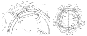
FIG. 1 illustrates a perspective view of a portion of a tilt pad journal bearing 100, and FIG. 2 illustrates a cross-sectional view of the tilt pad journal bearing 100 having a bearing cage 102 disposed circumferentially thereabout, according to one or more embodiments described. Referring to FIGS. 1 and 2, the journal bearing 100 may be adapted to engage and support a rotatable shaft (not shown) in a turbomachine. At least one journal bearing 100 may be disposed proximate each axial end of the shaft and adapted to support a radial load thereof. As will be appreciated by those of skill in the art, the bearing 100 may be used in a variety of turbomachine applications, such as turbines, compressors, pumps, etc.
The journal bearing 100 may include a support structure 102 (FIG. 2), or annular bearing cage, having a first, radially-outer surface 104 and a second, radially-inner surface 106. A bearing housing (not shown) may be disposed radially-outward from the outer surface 104 of the bearing cage 102, thereby maintaining the support structure aligned. One or more pivots 110 (five are shown) may be disposed radially-inward from the bearing cage 102. Each pivot 110 may have a first, outer surface 112 and a second, inner surface 114. The outer surface 112 of each pivot 110 may be coupled to and/or engaged with the inner surface 106 of the bearing cage 102. In at least one embodiment, the outer surface 112 may be generally flat, and the inner surface 114 may be arcuate, as illustrated.
One or more pads 120 (five are shown) may be disposed radially-inward from the respective pivots 110. Each pad 120 may have a first, outer surface 122 and a second, inner surface 124. The outer surface 122 of the pad 120 may be coupled to the inner surface 114 of the corresponding pivot 110. In operation, the arcuate inner surface 114 enables the pad 120 to move freely or “tilt” when supporting the shaft to accommodate shaft misalignment and reduce edge loading of the pads 120. Moreover, the pivots 110 enable the pads 120 to tilt from side-to-side in a radial plane with respect to a longitudinal axis 150 through the journal bearing 100. In other embodiments, the pivots 110 may enable the pads 120 to tilt from side-to-side in the radial plane with respect to the longitudinal axis 150 through the journal bearing 100, from side-to side in an axial plane with respect to the longitudinal axis 150, and all angles therebetween, i.e., move/rotate as a ball and socket joint. Although five circumferentially-offset pads 120 are shown, it is contemplated that the number of pads 120, and the circumferential spacing of the pads 120, may vary.
The bearing cage 102 may define one or more support structure channels or cage channels 130 extending from the outer surface 104 of the bearing cage 102 to the inner surface 106 of the bearing cage 102. Each pivot 110 may define one or more pivot channels 132 that extend from the outer surface 112 of the pivot 110 to the inner surface 114 of the pivot 110. Each pivot channel 132 may be in fluid communication with and contiguous with a corresponding cage channel 130. Each pad 120 may define one or more pad channels 134 that extend from the outer surface 122 of the pad 120 to one or more openings 136 (one is shown) in the inner surface 124 of the pad 120. Each pad channel 134 may be in fluid communication with and contiguous with a corresponding pivot channel 132. Thus, a path of fluid communication may extend from the outer surface 104 of the bearing cage 102, through the pivot 110 (via the pivot channel 132), and to the opening 136 in the inner surface 124 of the pad 120.
The opening 136 may be disposed proximate the leading edge 140 of the inner surface 124, the trailing edge 142 of the inner surface 124, or anywhere therebetween. As shown, the opening 136 is an axially-extending slot disposed proximate the leading edge 140 of the pad 120. In other embodiments, the opening 136 may include a plurality of openings 136 (not shown). For example, the openings 136 may be axially-spaced apart along the inner surface 124 of the pad 120, i.e., between first and second axial ends 144, 146 (see FIG. 1) of the pad 120. The opening(s) 136 may have any cross-sectional shape including, but not limited to, a circle, an oval, a square, a rectangle, combinations thereof, or the like. The cross-sectional area of the opening(s) 136 may be varied depending on typical operating conditions of the turbomachine, such as rotational speed, potential friction, temperature constraints, and frequency of use.
In operation, a lubricant, e.g., oil, may be introduced and/or injected to the inner surface 124 of the pads 120 to reduce the friction, and associated heat, between the pads 120 and the rotating shaft. The lubricant may be introduced to the cage channel 130 proximate the outer surface 104 of the bearing cage 102 and flow therethrough toward the inner surface 106 of the bearing cage 102 proximate the pivot 110. The lubricant may then flow from the cage channel 130 into and through the pivot channel 132. The lubricant may then flow from the pivot channel 132 into and through the pad channel 134 to the opening 136 in the inner surface 124 of the pad 120. One or more flow control devices (not shown) may be disposed in the cage channel 130, the pivot channel 132, and/or the pad channel 134 to adjust the rate at which the lubricant flows therethrough.
The axially-extending opening 136 may enable the lubricant to be distributed across the axial width of the pads 120. Further, the opening 136 may be disposed proximate the leading edge 140 of the pads 120 such that a shaft rotating in the clockwise direction, as viewed in FIGS. 1 and 2, may distribute the lubricant along the at least partially circumferential length of the pad 120 to the trailing edge 142. If it is desired to rotate the shaft in the opposite direction, the pads 120 may be rotated 180°. In another embodiment, the pads 120 may be removed from the bearing cage 102 and replaced with pads 120 having openings 136 in what is now the new leading edge 140. In this way, the bearing cage 102 is independent from the direction that the shaft rotates.
In at least one embodiment, the journal bearing 100 may be a primary bearing adapted to contact and support the shaft during normal operation of the turbomachine. In another embodiment, the journal bearing 100 may be an auxiliary bearing adapted to contact and support the shaft when the primary bearings are inactive or otherwise fail.
FIG. 3 illustrates a perspective view of a portion of a tilt pad thrust bearing 400, FIG. 4 illustrates a top view of a portion of the tilt pad thrust bearing 400 depicted in FIG. 3, and FIG. 5 illustrates a cross-sectional view of the tilt pad thrust bearing 400 depicted in FIG. 4 taken along line V-V, according to one or more embodiments described. Referring to FIGS. 3-5, the thrust bearing 400 may include a support structure 402 having a first surface 404 and a second surface 406. In at least one embodiment, the support structure 402 may be an annular support ring having a first axial surface 404 and a second axial surface 406. An outer radial surface 408 of the support ring 402 may be coupled to or integral with a stationary portion of the turbomachine, e.g., the casing, and an inner radial surface 410 of the support ring 402 may be disposed radially-outward from the shaft.
A plurality of pivots 412 may be coupled to the second axial surface 406 of the support ring 402. Each pivot 412 may include a first surface 414 and a second surface 416. In at least one embodiment, the first surface 414 may be generally flat, and the second surface 416 may be arcuate. The first surface 414 may be coupled to the second axial surface 406 of the support ring 402. The second surface 416 may be coupled to and/or engaged with a first axial surface 422 of a pad 420. The pad 420 may be coupled to the pivot 412 such that the pad 420 may move freely or “tilt” to accommodate axial misalignment and prevent edge loading of the pad 420. A second axial surface 424 of the pad 420 may be adapted to engage and withstand axial thrusts derived from an annular disc (not shown) coupled to the shaft. In FIG. 3, one pad 420 has been removed to provide a view of the second axial end 406 of the support ring 402 and a pivot 412.
The support ring 402 may define a support structure channel or ring channel 430 extending from the first axial surface 404 of the support ring 402 to the second axial surface 406 of the support ring 402. The ring channel 430 may be in fluid communication with and contiguous with a pivot channel 432, which extends generally from the first axial surface 414 of the pivot 412 to the second axial surface 416 of the pivot 412. The pivot channel 432 may be in fluid communication with and contiguous with a pad channel 434, which extends generally from the first axial surface 422 of the pad 420 to one or more openings 436 (one is shown) in the second axial surface 424 of the pad 420. Thus, a path of fluid communication may extend from the first axial surface 404 of the support ring 402, through the pivot 412 (via the pivot channel 432), and to the opening 436 in the second axial surface 424 of the pad 420.
The opening 436 may be disposed proximate the leading edge 440 of the second axial surface 424, the trailing edge 442 of the second axial surface 424, or anywhere therebetween. As shown, the opening 436 is a radially-extending slot disposed proximate the leading edge 440 of the pad 102. In at least one embodiment, the pad channel 434 may be fluidly coupled generally to the center of the opening 436, i.e., equidistant between first and second radial ends 444, 446 of the pad 420. In another embodiment, the pad channel 434 may be fluidly coupled to the opening 436 closer to one radial end 446 than the other radial end 444, as shown. As such, the position of the channel 434 relative to the radial ends 444, 446 may influence the oil velocity distribution in the opening 436 and impact the temperature of the pad 420.
The opening 436 may include a plurality of openings (not shown). For example, the openings 436 may be radially spaced apart along the second axial surface 424 of the pad 420, i.e., between the first and second radial ends 444, 446 of the pad 420. The opening(s) 436 may have any cross-sectional shape including, but not limited to, a circle, an oval, a square, a rectangle, combinations thereof, or the like. The cross-sectional area of the opening(s) 436 may be varied depending on operating conditions of the turbomachine, such as friction, temperature, and frequency of use.
In operation, the lubricating fluid may be introduced and/or injected to the second axial surface 424 of the pads 420 to reduce the friction, and associated heat, between the pads 420 and the rotating annular disc coupled to the shaft. The lubricant may be introduced to the ring channel 430 proximate the first axial surface 404 of the support ring 402 and flow therethrough to the second axial surface 406 of the support ring 402 proximate the pivot 412. The lubricant may then flow from the ring channel 430 into and through the pivot channel 432. The lubricant may then flow from the pivot channel 432 into and through the pad channel 434 to the opening 436 in the second axial surface 424 of the pad 420. One or more flow control devices (not shown) may be disposed in the ring channel 430, the pivot channel 432, and/or the pad channel 434 to adjust the rate at which the lubricant flows therethrough.
The radially-extending opening 436 may enable the lubricant to be distributed across the radial width of the pads 420. Further, the opening 436 may be disposed proximate the leading edge 440 of the pads 420 such that the rotation of the annular disc may distribute the lubricant along the at least partially circumferential length of the pad 420 to the trailing edge 442. If it is desired to rotate the shaft in the opposite direction, the pads 420 may be rotated 180°. In another embodiment, the pads 420 may be removed from the support ring 402 and replaced with pads 420 having openings 436 in what is now the new leading edge 440. In this way, the support ring 402 is independent from the direction that the shaft rotates.
FIG. 6 is a flowchart of a method 600 of lubricating a tilt pad bearing, according to one or more embodiments disclosed. The method may include introducing lubricant through a support structure channel defined by a support structure, as shown at 602. The lubricant may then flow from the support structure channel into a pivot channel defined by a pivot and fluidly coupled to the support structure channel, as shown at 604. The pivot may be coupled to the support structure. The lubricant may then flow from the pivot channel into a pad channel defined by a pad and fluidly coupled to the pivot channel, as shown at 606. The pad may be coupled to the pivot such that the pad is adapted to tilt with respect to the support structure.
The foregoing has outlined features of several embodiments so that those skilled in the art may better understand the present disclosure. Those skilled in the art should appreciate that they may readily use the present disclosure as a basis for designing or modifying other processes and structures for carrying out the same purposes and/or achieving the same advantages of the embodiments introduced herein. Those skilled in the art should also realize that such equivalent constructions do not depart from the spirit and scope of the present disclosure, and that they may make various changes, substitutions and alterations herein without departing from the spirit and scope of the present disclosure.

Claims (13)

We claim:
1. A tilt pad bearing, comprising:
a support structure having first and second support structure surfaces;
a pivot having first and second pivot surfaces, the first pivot surface being coupled to the second support structure surface;
a pad having first and second pad surfaces, the first pad surface being coupled to the second pivot surface and the second pad surface being configured to contact and support a rotating shaft; and
a path of fluid communication extending from the first support structure surface, through the pivot, and to an opening in the second pad surface, the opening being disposed proximate a leading edge of the pad.
2. The tilt pad bearing of claim 1, wherein the tilt pad bearing further comprises a tilt pad journal bearing, and wherein the support structure comprises a bearing cage.
3. The tilt pad bearing of claim 1, wherein the tilt pad bearing further comprises a tilt pad thrust bearing, and wherein the support structure comprises a support ring.
4. The tilt pad bearing of claim 1, wherein the path of fluid communication further comprises:
a support structure channel extending from the first support structure surface to the second support structure surface;
a pivot channel fluidly coupled to the support structure channel and extending to the second pivot surface; and
a pad channel fluidly coupled to the pivot channel and extending to the opening in the second pad surface.
5. The tilt pad bearing of claim 4, wherein a lubricant is adapted to flow through the path of fluid communication to the second pad surface.
6. The tilt pad bearing of claim 5, wherein the lubricant is oil.
7. The tilt pad bearing of claim 1, wherein the opening comprises at least one of an axially-extending slot and a radially-extending slot.
8. A tilt pad bearing, comprising:
a support structure having first and second support structure surfaces and a support structure channel extending between the first and second support structure surfaces;
a pivot having first and second pivot surfaces, the first pivot surface being coupled to the second support structure surface, the pivot defining a pivot channel that extends between the first and second pivot surfaces and is in fluid communication with the support structure channel; and
a pad having first and second pad surfaces, the first pad surface being coupled to the second pivot surface and the second pad surface being configured to contact and support a rotating shaft, the pad defining a pad channel that extends from the first pad surface to the second pad surface and is in fluid communication with the pivot channel,
wherein the support structure channel, the pivot channel, and the pad channel define a path of fluid communication from the first support structure surface to an opening in the second pad surface, the opening being disposed proximate a leading edge of the pad.
9. The tilt pad bearing of claim 8, wherein tilt pad bearing further comprises a tilt pad journal bearing, and wherein the support structure comprises a bearing cage.
10. The tilt pad bearing of claim 8, wherein the tilt pad bearing further comprises a tilt pad thrust bearing, and wherein the support structure comprises a support ring.
11. A method of lubricating a tilt pad bearing, comprising:
introducing a lubricant to a support structure channel defined by a support structure;
flowing the lubricant from the support structure channel into a pivot channel defined by a pivot having first and second pivot surfaces, the pivot channel fluidly coupled to the support structure channel, wherein the first pivot surface is coupled to the support structure;
flowing the lubricant from the pivot channel into a pad channel defined by a pad comprising:
a first pad surface coupled to the second pivot surface; and
a second pad surface configured to contact and support a rotating shaft, wherein the pad channel extends from the first pad surface to the second pad surface and is fluidly coupled to the pivot channel, the pad being coupled to the pivot such that the pad is adapted to tilt with respect to the support structure; and
flowing the lubricant from the pad channel through an opening in the second pad surface, the opening being disposed proximate a leading edge of the pad.
12. The method of claim 11, wherein the tilt pad bearing comprises a tilt pad journal bearing, and wherein the support structure comprises a bearing cage.
13. The method of claim 11, wherein the tilt pad bearing comprises a tilt pad thrust bearing, and wherein the support structure comprises a support ring.
US14/344,932 2011-09-21 2012-09-14 Tilt pad bearing with through-pivot lubrication Active 2033-07-16 US9739310B2 (en)

Priority Applications (1)

Application Number Priority Date Filing Date Title
US14/344,932 US9739310B2 (en) 2011-09-21 2012-09-14 Tilt pad bearing with through-pivot lubrication

Applications Claiming Priority (3)

Application Number Priority Date Filing Date Title
US201161537339P 2011-09-21 2011-09-21
PCT/US2012/055459 WO2013043495A1 (en) 2011-09-21 2012-09-14 Tilt pad bearing with through-pivot lubrication
US14/344,932 US9739310B2 (en) 2011-09-21 2012-09-14 Tilt pad bearing with through-pivot lubrication

Publications (2)

Publication Number Publication Date
US20150159692A1 US20150159692A1 (en) 2015-06-11
US9739310B2 true US9739310B2 (en) 2017-08-22

Family

ID=47914776

Family Applications (1)

Application Number Title Priority Date Filing Date
US14/344,932 Active 2033-07-16 US9739310B2 (en) 2011-09-21 2012-09-14 Tilt pad bearing with through-pivot lubrication

Country Status (3)

Country Link
US (1) US9739310B2 (en)
EP (1) EP2758679A4 (en)
WO (1) WO2013043495A1 (en)

Cited By (3)

* Cited by examiner, † Cited by third party
Publication number Priority date Publication date Assignee Title
US20160123391A1 (en) * 2013-08-01 2016-05-05 Ihi Corporation Tilting-pad bearing and turbo compressor
US20190085832A1 (en) * 2017-09-20 2019-03-21 Siemens Gamesa Renewable Energy A/S Wind turbine
WO2023046974A1 (en) 2021-09-27 2023-03-30 Voith Patent Gmbh Tilting pad bearing, in particular radial tilting pad bearing

Families Citing this family (11)

* Cited by examiner, † Cited by third party
Publication number Priority date Publication date Assignee Title
JP6184299B2 (en) * 2013-11-08 2017-08-23 三菱日立パワーシステムズ株式会社 Tilting pad type thrust bearing and rotating machine equipped with the same
JP6038088B2 (en) * 2014-09-22 2016-12-07 三菱重工業株式会社 Bearings and bearing pads
US9874247B2 (en) * 2016-05-09 2018-01-23 Elliott Company Internal cooling bearing pads
KR101871043B1 (en) * 2016-06-30 2018-06-25 두산중공업 주식회사 Tilting Pad Journal Bearings with Ball-Socket
US10323687B2 (en) * 2016-09-07 2019-06-18 New Way Machine Components, Inc. Snap joint for externally pressurized gas bearings
US11333194B2 (en) * 2018-03-15 2022-05-17 Sulzer Management Ag Pad for a tilting pad thrust bearing assembly and thrust bearing assembly
US10774873B2 (en) * 2018-06-11 2020-09-15 Trane International Inc. Porous gas bearing
US10753392B2 (en) 2018-06-11 2020-08-25 Trane International Inc. Porous gas bearing
CN109340255B (en) * 2018-08-22 2020-06-16 株洲季元科技有限责任公司 Spherical hinge joint composite bearing structure of rolling-resisting torsion bar device of locomotive vehicle
DE102019118440B4 (en) 2019-07-08 2022-03-03 Miba Industrial Bearings Germany Gmbh Hydrodynamic plain bearing
KR102426623B1 (en) * 2020-02-07 2022-07-28 두산에너빌리티 주식회사 Bearing and Power generating equipment comprising the same

Citations (29)

* Cited by examiner, † Cited by third party
Publication number Priority date Publication date Assignee Title
US3687510A (en) * 1970-11-12 1972-08-29 Westinghouse Electric Corp Pivoted pad journal bearing
US3982796A (en) * 1973-02-28 1976-09-28 The Glacier Metal Company Limited Thrust bearings
US4247157A (en) * 1978-11-10 1981-01-27 Maag Gear-Wheel & Machine Company Ltd. Cant segment-radial bearing for heavily loaded high-speed shafts
US4335925A (en) * 1978-11-02 1982-06-22 The Glacier Metal Company, Limited Thrust bearing
FR2507265A1 (en) 1981-06-05 1982-12-10 Technip Cie DEVICE FOR FACILITATING MOVEMENT BETWEEN TWO ORGANS, SUCH AS A BEARING OR A STOP, WITH OSCILLATING SKATES
JPS5837312A (en) 1981-08-28 1983-03-04 Hitachi Ltd Pad type journal bearing
US4456391A (en) * 1981-09-30 1984-06-26 Aeplc Tilting pad thrust bearing
US4597676A (en) * 1984-04-30 1986-07-01 General Electric Company Hybrid bearing
US4699524A (en) * 1986-05-09 1987-10-13 Canadian General Electric Company Limited Supplementary cooling system for thrust bearing
US5288153A (en) * 1993-01-04 1994-02-22 Delaware Capital Formation, Inc. Tilting pad journal bearing using directed lubrication
US5482380A (en) * 1994-08-24 1996-01-09 Corratti; Anthony A. Double tilting pad journal bearing
US5720558A (en) * 1995-10-16 1998-02-24 Dresser-Rand Company Tilting bearing pad with an axial feed groove having an exit side profiled area
US5738447A (en) * 1997-04-01 1998-04-14 Rotating Machinery Technology, Inc. Pad bearing assembly with fluid spray and blocker bar
US5743657A (en) * 1994-08-06 1998-04-28 The Glacier Metal Company Limited Tilting pad journal bearing
WO1998045608A1 (en) 1997-04-09 1998-10-15 Pioneer Motor Bearing Co. Hydrostatically supported tilting pad journal bearing improvements
US6000851A (en) * 1997-12-10 1999-12-14 The United States Of America As Represented By The Secretary Of The Navy Adjustable electric motor bearing system
WO2000011360A1 (en) 1998-08-19 2000-03-02 Corac Group Plc Hydrodynamic journal bearing
JP2001124062A (en) * 1999-10-21 2001-05-08 Hitachi Ltd Tilting pad bearing device
US20020141670A1 (en) * 2001-03-28 2002-10-03 Nicholas John C. Sleeve bearing with bypass cooling
US6739756B2 (en) 2001-03-12 2004-05-25 Whm Holding Corporation Combination thrust bearing and journal bearing, and method for distributing fluid to same
US6746152B2 (en) * 2001-07-27 2004-06-08 Pioneer Motor Bearing Company Thrust bearing and method for equalizing load
US7237957B2 (en) * 2005-02-28 2007-07-03 Kingsbury, Inc. Journal bearing having self-retaining shoes and method of using the same to support a rotating shaft
KR20070098126A (en) 2006-03-31 2007-10-05 (주)터보링크 Tilting 5-pad journal bearing of turbine and generators for the reduction of shaft vibration and bearing metal temperature
KR20090128849A (en) * 2008-06-11 2009-12-16 두산중공업 주식회사 Tilting pad journal bearing installed stepped seal tooth at oil supply zone position between bearing pads
US20100215299A1 (en) 2009-02-25 2010-08-26 Waki Yuichiro Oiling nozzle for thrust bearing
US20100220944A1 (en) 2009-02-27 2010-09-02 Waki Yuichiro Journal bearing
US8366323B2 (en) * 2008-11-12 2013-02-05 Mitsubishi Heavy Industries, Ltd. Rotation shaft supporting structure with journal bearing and assembling method of the bearing
US20140270607A1 (en) * 2013-03-13 2014-09-18 Waukesha Bearings Corporation Trailing Edge Cooling On Hydrodynamic Bearings
US9022658B2 (en) * 2012-06-01 2015-05-05 Alstom Technology Ltd Journal bearing pad for turbine

Patent Citations (32)

* Cited by examiner, † Cited by third party
Publication number Priority date Publication date Assignee Title
US3687510A (en) * 1970-11-12 1972-08-29 Westinghouse Electric Corp Pivoted pad journal bearing
US3982796A (en) * 1973-02-28 1976-09-28 The Glacier Metal Company Limited Thrust bearings
US4335925A (en) * 1978-11-02 1982-06-22 The Glacier Metal Company, Limited Thrust bearing
US4247157A (en) * 1978-11-10 1981-01-27 Maag Gear-Wheel & Machine Company Ltd. Cant segment-radial bearing for heavily loaded high-speed shafts
FR2507265A1 (en) 1981-06-05 1982-12-10 Technip Cie DEVICE FOR FACILITATING MOVEMENT BETWEEN TWO ORGANS, SUCH AS A BEARING OR A STOP, WITH OSCILLATING SKATES
JPS5837312A (en) 1981-08-28 1983-03-04 Hitachi Ltd Pad type journal bearing
US4456391A (en) * 1981-09-30 1984-06-26 Aeplc Tilting pad thrust bearing
US4597676A (en) * 1984-04-30 1986-07-01 General Electric Company Hybrid bearing
US4699524A (en) * 1986-05-09 1987-10-13 Canadian General Electric Company Limited Supplementary cooling system for thrust bearing
US5288153A (en) * 1993-01-04 1994-02-22 Delaware Capital Formation, Inc. Tilting pad journal bearing using directed lubrication
US5743657A (en) * 1994-08-06 1998-04-28 The Glacier Metal Company Limited Tilting pad journal bearing
US5482380A (en) * 1994-08-24 1996-01-09 Corratti; Anthony A. Double tilting pad journal bearing
US5720558A (en) * 1995-10-16 1998-02-24 Dresser-Rand Company Tilting bearing pad with an axial feed groove having an exit side profiled area
US5738447A (en) * 1997-04-01 1998-04-14 Rotating Machinery Technology, Inc. Pad bearing assembly with fluid spray and blocker bar
WO1998045608A1 (en) 1997-04-09 1998-10-15 Pioneer Motor Bearing Co. Hydrostatically supported tilting pad journal bearing improvements
US6000851A (en) * 1997-12-10 1999-12-14 The United States Of America As Represented By The Secretary Of The Navy Adjustable electric motor bearing system
WO2000011360A1 (en) 1998-08-19 2000-03-02 Corac Group Plc Hydrodynamic journal bearing
US6623164B1 (en) * 1998-08-19 2003-09-23 Corac Group Plc Hydrodynamic journal bearing
JP2001124062A (en) * 1999-10-21 2001-05-08 Hitachi Ltd Tilting pad bearing device
US6739756B2 (en) 2001-03-12 2004-05-25 Whm Holding Corporation Combination thrust bearing and journal bearing, and method for distributing fluid to same
US20020141670A1 (en) * 2001-03-28 2002-10-03 Nicholas John C. Sleeve bearing with bypass cooling
WO2002079657A2 (en) 2001-03-28 2002-10-10 Rotating Machinery Technology, Inc. Bearing assembly with bypass cooling
US6485182B2 (en) * 2001-03-28 2002-11-26 Rotating Machinery Technology, Inc. Sleeve bearing with bypass cooling
US6746152B2 (en) * 2001-07-27 2004-06-08 Pioneer Motor Bearing Company Thrust bearing and method for equalizing load
US7237957B2 (en) * 2005-02-28 2007-07-03 Kingsbury, Inc. Journal bearing having self-retaining shoes and method of using the same to support a rotating shaft
KR20070098126A (en) 2006-03-31 2007-10-05 (주)터보링크 Tilting 5-pad journal bearing of turbine and generators for the reduction of shaft vibration and bearing metal temperature
KR20090128849A (en) * 2008-06-11 2009-12-16 두산중공업 주식회사 Tilting pad journal bearing installed stepped seal tooth at oil supply zone position between bearing pads
US8366323B2 (en) * 2008-11-12 2013-02-05 Mitsubishi Heavy Industries, Ltd. Rotation shaft supporting structure with journal bearing and assembling method of the bearing
US20100215299A1 (en) 2009-02-25 2010-08-26 Waki Yuichiro Oiling nozzle for thrust bearing
US20100220944A1 (en) 2009-02-27 2010-09-02 Waki Yuichiro Journal bearing
US9022658B2 (en) * 2012-06-01 2015-05-05 Alstom Technology Ltd Journal bearing pad for turbine
US20140270607A1 (en) * 2013-03-13 2014-09-18 Waukesha Bearings Corporation Trailing Edge Cooling On Hydrodynamic Bearings

Non-Patent Citations (2)

* Cited by examiner, † Cited by third party
Title
PCT International Preliminary Report on Patentability for International Application No. PCT/US2012/055459 dated Oct. 22, 2013.
PCT International Search Report for International Application No. PCT/US2012/055459 dated Feb. 28, 2013.

Cited By (6)

* Cited by examiner, † Cited by third party
Publication number Priority date Publication date Assignee Title
US20160123391A1 (en) * 2013-08-01 2016-05-05 Ihi Corporation Tilting-pad bearing and turbo compressor
US10247239B2 (en) * 2013-08-01 2019-04-02 Ihi Rotating Machinery Engineering Co., Ltd. Tilting-pad bearing and turbo compressor
US20190085832A1 (en) * 2017-09-20 2019-03-21 Siemens Gamesa Renewable Energy A/S Wind turbine
US10584685B2 (en) * 2017-09-20 2020-03-10 Siemens Gamesa Renewable Energy A/S Wind turbine
WO2023046974A1 (en) 2021-09-27 2023-03-30 Voith Patent Gmbh Tilting pad bearing, in particular radial tilting pad bearing
DE102021124857A1 (en) 2021-09-27 2023-03-30 Voith Patent Gmbh Tilting pad bearings, in particular radial tilting pad plain bearings

Also Published As

Publication number Publication date
US20150159692A1 (en) 2015-06-11
EP2758679A1 (en) 2014-07-30
WO2013043495A1 (en) 2013-03-28
EP2758679A4 (en) 2016-01-20

Similar Documents

Publication Publication Date Title
US9739310B2 (en) Tilt pad bearing with through-pivot lubrication
EP3299686B1 (en) Sliding component
US8628247B2 (en) Bearing structure of turbocharger
US7470064B2 (en) Axial thrust bearing
JP6471090B2 (en) Axial bearing device
JP5863422B2 (en) Thrust bearing and rotating machine
US10520026B2 (en) Bearing structure and turbocharger
US9599152B2 (en) Compact squeeze film damper bearing
EP3627011A1 (en) Sliding component
US10415635B2 (en) Tilting pad journal bearing
US20130336608A1 (en) Bearing assembly for use with a turbine engine
JP6410006B2 (en) Tilting pad bearing and turbo compressor
KR102055517B1 (en) Journal bearing and rolling machine
EP3851690B1 (en) Damper bearing and damper
US9377051B2 (en) Duplex bearing device
US10385921B2 (en) Combination bearing and seal assembly for rotatable shafts
US11168793B2 (en) Sliding component
JP2014125921A (en) Ball bearing unit for turbocharger
WO2019087890A1 (en) Tilting pad bearing
WO2019142383A1 (en) Tilting pad bearing device and rotating machine
US20190048924A1 (en) Journal device and rotary machine
CN110657123B (en) Sealing device for refrigerant compressor
US11143242B2 (en) Journal Device and rotary machine
JP2016113937A (en) Bearing mechanism for turbocharger
JP2006077871A (en) Bearing structure

Legal Events

Date Code Title Description
AS Assignment

Owner name: DRESSER-RAND COMPANY, NEW YORK

Free format text: ASSIGNMENT OF ASSIGNORS INTEREST;ASSIGNORS:DOURLENS, HERVE;LEMETTEIL, CLAUDE;REEL/FRAME:034047/0299

Effective date: 20141022

STCF Information on status: patent grant

Free format text: PATENTED CASE

MAFP Maintenance fee payment

Free format text: PAYMENT OF MAINTENANCE FEE, 4TH YEAR, LARGE ENTITY (ORIGINAL EVENT CODE: M1551); ENTITY STATUS OF PATENT OWNER: LARGE ENTITY

Year of fee payment: 4

AS Assignment

Owner name: SIEMENS ENERGY, INC., FLORIDA

Free format text: MERGER;ASSIGNOR:DRESSER-RAND COMPANY;REEL/FRAME:062886/0944

Effective date: 20221205