JP6184299B2 - Tilting pad type thrust bearing and rotating machine equipped with the same - Google Patents
Tilting pad type thrust bearing and rotating machine equipped with the same Download PDFInfo
- Publication number
- JP6184299B2 JP6184299B2 JP2013232028A JP2013232028A JP6184299B2 JP 6184299 B2 JP6184299 B2 JP 6184299B2 JP 2013232028 A JP2013232028 A JP 2013232028A JP 2013232028 A JP2013232028 A JP 2013232028A JP 6184299 B2 JP6184299 B2 JP 6184299B2
- Authority
- JP
- Japan
- Prior art keywords
- pad
- guide groove
- sliding surface
- opening
- thrust bearing
- Prior art date
- Legal status (The legal status is an assumption and is not a legal conclusion. Google has not performed a legal analysis and makes no representation as to the accuracy of the status listed.)
- Expired - Fee Related
Links
Images


Classifications
-
- F—MECHANICAL ENGINEERING; LIGHTING; HEATING; WEAPONS; BLASTING
- F16—ENGINEERING ELEMENTS AND UNITS; GENERAL MEASURES FOR PRODUCING AND MAINTAINING EFFECTIVE FUNCTIONING OF MACHINES OR INSTALLATIONS; THERMAL INSULATION IN GENERAL
- F16C—SHAFTS; FLEXIBLE SHAFTS; ELEMENTS OR CRANKSHAFT MECHANISMS; ROTARY BODIES OTHER THAN GEARING ELEMENTS; BEARINGS
- F16C33/00—Parts of bearings; Special methods for making bearings or parts thereof
- F16C33/02—Parts of sliding-contact bearings
- F16C33/04—Brasses; Bushes; Linings
- F16C33/06—Sliding surface mainly made of metal
- F16C33/10—Construction relative to lubrication
- F16C33/1025—Construction relative to lubrication with liquid, e.g. oil, as lubricant
- F16C33/106—Details of distribution or circulation inside the bearings, e.g. details of the bearing surfaces to affect flow or pressure of the liquid
- F16C33/1065—Grooves on a bearing surface for distributing or collecting the liquid
-
- F—MECHANICAL ENGINEERING; LIGHTING; HEATING; WEAPONS; BLASTING
- F04—POSITIVE - DISPLACEMENT MACHINES FOR LIQUIDS; PUMPS FOR LIQUIDS OR ELASTIC FLUIDS
- F04D—NON-POSITIVE-DISPLACEMENT PUMPS
- F04D29/00—Details, component parts, or accessories
- F04D29/04—Shafts or bearings, or assemblies thereof
- F04D29/041—Axial thrust balancing
- F04D29/0413—Axial thrust balancing hydrostatic; hydrodynamic thrust bearings
-
- F—MECHANICAL ENGINEERING; LIGHTING; HEATING; WEAPONS; BLASTING
- F16—ENGINEERING ELEMENTS AND UNITS; GENERAL MEASURES FOR PRODUCING AND MAINTAINING EFFECTIVE FUNCTIONING OF MACHINES OR INSTALLATIONS; THERMAL INSULATION IN GENERAL
- F16C—SHAFTS; FLEXIBLE SHAFTS; ELEMENTS OR CRANKSHAFT MECHANISMS; ROTARY BODIES OTHER THAN GEARING ELEMENTS; BEARINGS
- F16C17/00—Sliding-contact bearings for exclusively rotary movement
- F16C17/04—Sliding-contact bearings for exclusively rotary movement for axial load only
- F16C17/06—Sliding-contact bearings for exclusively rotary movement for axial load only with tiltably-supported segments, e.g. Michell bearings
-
- F—MECHANICAL ENGINEERING; LIGHTING; HEATING; WEAPONS; BLASTING
- F16—ENGINEERING ELEMENTS AND UNITS; GENERAL MEASURES FOR PRODUCING AND MAINTAINING EFFECTIVE FUNCTIONING OF MACHINES OR INSTALLATIONS; THERMAL INSULATION IN GENERAL
- F16C—SHAFTS; FLEXIBLE SHAFTS; ELEMENTS OR CRANKSHAFT MECHANISMS; ROTARY BODIES OTHER THAN GEARING ELEMENTS; BEARINGS
- F16C33/00—Parts of bearings; Special methods for making bearings or parts thereof
- F16C33/02—Parts of sliding-contact bearings
- F16C33/04—Brasses; Bushes; Linings
- F16C33/06—Sliding surface mainly made of metal
- F16C33/10—Construction relative to lubrication
- F16C33/1025—Construction relative to lubrication with liquid, e.g. oil, as lubricant
- F16C33/106—Details of distribution or circulation inside the bearings, e.g. details of the bearing surfaces to affect flow or pressure of the liquid
- F16C33/1085—Channels or passages to recirculate the liquid in the bearing
-
- F—MECHANICAL ENGINEERING; LIGHTING; HEATING; WEAPONS; BLASTING
- F16—ENGINEERING ELEMENTS AND UNITS; GENERAL MEASURES FOR PRODUCING AND MAINTAINING EFFECTIVE FUNCTIONING OF MACHINES OR INSTALLATIONS; THERMAL INSULATION IN GENERAL
- F16C—SHAFTS; FLEXIBLE SHAFTS; ELEMENTS OR CRANKSHAFT MECHANISMS; ROTARY BODIES OTHER THAN GEARING ELEMENTS; BEARINGS
- F16C2300/00—Application independent of particular apparatuses
- F16C2300/30—Application independent of particular apparatuses related to direction with respect to gravity
- F16C2300/34—Vertical, e.g. bearings for supporting a vertical shaft
Description
本発明は、ティルティングパッド式スラスト軸受及びこれを備えた回転機械に関する。 The present invention relates to a tilting pad type thrust bearing and a rotary machine including the same.
一般に、火力発電設備等で用いられる蒸気タービンは、回転軸を介して発電機と連結されている。この回転軸は、水平方向へ延在するように設置されており、その回転軸の自重を含む径方向荷重を受ける複数のジャーナル軸受が設けられている。また、蒸気タービンにおいては、回転軸の回転速度や負荷状態によって流体力が変動しており、この流体力によって回転軸の軸方向荷重も生じる。そのため、この回転軸の軸方向荷重を受けるとともに回転軸の軸方向変位を抑えるスラスト軸受が設けられている。 Generally, a steam turbine used in a thermal power generation facility or the like is connected to a generator via a rotating shaft. The rotating shaft is installed so as to extend in the horizontal direction, and a plurality of journal bearings that receive a radial load including the weight of the rotating shaft are provided. In the steam turbine, the fluid force fluctuates depending on the rotation speed and load state of the rotation shaft, and an axial load on the rotation shaft is also generated by the fluid force. Therefore, a thrust bearing is provided that receives the axial load of the rotating shaft and suppresses the axial displacement of the rotating shaft.
負荷能力が高いスラスト軸受として、ティルティングパッド式スラスト軸受が知られている(例えば特許文献1参照)。特許文献1に記載のティルティングパッド式スラスト軸受は、スラストカラーに対向するように回転軸の外周側に配置され、揺動可能に設けられた複数のパッドと、複数のパッドの間に設けられた複数の給油片とを備えている。そして、給油片の給油孔から供給された潤滑油は、スラストカラーの回転に伴い、スラストカラーとパッドの摺動面の間に流入して油膜を形成する。この油膜により、軸方向荷重を支持するようになっている。
A tilting pad type thrust bearing is known as a thrust bearing having a high load capacity (see, for example, Patent Document 1). The tilting pad type thrust bearing described in
しかしながら、上記従来技術には次のような改善の余地がある。すなわち、特許文献1には明確に記載されていないものの、スラストカラーとパッドの摺動面の間に供給された潤滑油は、パッドの後端(言い換えれば、周方向下流側)からだけでなく、パッドの外周端(言い換えれば、径方向外側)及び内周端(言い換えれば、径方向内側)からも流出する。そして、パッドの外周端及び内周端から流出した潤滑油が、軸受の外部へ排出される。そのため、そのぶん潤滑油を供給する必要があり、給油量の点で改善の余地があった。
However, the above prior art has room for improvement as follows. That is, although not clearly described in
本発明の目的は、給油量を低減できるティルティングパッド式スラスト軸受及びこれを備えた回転機械を提供することにある。 An object of the present invention is to provide a tilting pad type thrust bearing capable of reducing the amount of oil supply and a rotating machine including the same.
上記目的を達成するために、第1の発明は、回転軸の外周側に固定されたスラストカラーを介して、前記回転軸の軸方向荷重を受けるティルティングパッド式スラスト軸受において、前記スラストカラーに対向するように前記回転軸の外周側に配置され、揺動可能に設けられた複数のパッドと、前記複数のパッドの間若しくは前記複数のパッドの摺動面の前縁部に設けられた複数の給油口と、前記パッドの摺動面における幅方向中心よりも内周縁に近づけられた位置で周方向に延在するように形成された流出案内溝と、前記流出案内溝とは独立して、前記給油口より径方向内側に位置するように前記パッドの摺動面の前縁部に形成された流入案内溝とを有し、前記流出案内溝は、前記パッドの摺動面及び後端面に開口し、前記流入案内溝は、前記パッドの後端面における前記流出案内溝の開口と同じ径方向位置を含む開口を形成するように、前記パッドの前端面に開口し、且つ、前記パッドの摺動面における前記流出案内溝の開口と同じ径方向位置より径方向外側の領域を含む開口を形成するように、前記パッドの摺動面に開口する。 In order to achieve the above object, a first invention provides a tilting pad type thrust bearing that receives an axial load of the rotary shaft through a thrust collar fixed to the outer peripheral side of the rotary shaft. A plurality of pads disposed on the outer peripheral side of the rotating shaft so as to face each other and provided so as to be able to swing, and a plurality of pads provided between the plurality of pads or at a front edge portion of a sliding surface of the plurality of pads. And an outflow guide groove formed so as to extend in the circumferential direction at a position closer to the inner periphery than the center in the width direction on the sliding surface of the pad, and the outflow guide groove And an inflow guide groove formed in a front edge portion of the sliding surface of the pad so as to be located radially inward from the oil filler port, and the outflow guide groove includes a sliding surface and a rear end surface of the pad And the inflow guide groove is An opening in the front end surface of the pad and an opening of the outflow guide groove in the sliding surface of the pad so as to form an opening including the same radial position as the opening of the outflow guide groove in the rear end surface of the pad. And an opening is formed in the sliding surface of the pad so as to form an opening including a region radially outside the same radial position as.
第1の発明においては、流出案内溝によって、パッドの内周端からの潤滑油の排出を抑止でき、さらに、その潤滑油を後端側(すなわち、下流側パッドの前端側)に流出させることができる。そして、下流側パッドの流入案内溝によって、上流側パッドの流出案内溝から流出した比較的低温な潤滑油を、下流側パッドの摺動面に供給することができる。したがって、給油量を低減できる。 In the first invention, the outflow guide groove can prevent the lubricating oil from being discharged from the inner peripheral end of the pad, and the lubricating oil can flow out to the rear end side (that is, the front end side of the downstream pad). Can do. The relatively cold lubricating oil that has flowed out of the outflow guide groove of the upstream pad can be supplied to the sliding surface of the downstream pad by the inflow guide groove of the downstream pad. Therefore, the amount of oil supply can be reduced.
上記目的を達成するために、第2の発明は、回転軸の外周側に固定されたスラストカラーを介して、前記回転軸の軸方向荷重を受けるティルティングパッド式スラスト軸受において、前記スラストカラーに対向するように前記回転軸の外周側に配置され、揺動可能に設けられた複数のパッドと、前記複数のパッドの間若しくは前記複数のパッドの摺動面の前縁側に形成された複数の給油口と、前記パッドの摺動面における幅方向中心よりも外周縁に近づけられた位置で周方向に延在するように形成された流出案内溝と、前記給油口より径方向外側に位置し、前記流出案内溝とは独立して前記パッドの摺動面の前縁側に形成された流入案内溝とを有し、前記流出案内溝は、前記パッドの摺動面及び後端面に開口し、前記流入案内溝は、前記パッドの後端面における前記流出案内溝の開口と同じ径方向位置を含む開口を形成するように、前記パッドの前端面に開口し、且つ、前記パッドの摺動面における前記流出案内溝の開口と同じ径方向位置より径方向内側の領域を含む開口を形成するように、前記パッドの摺動面に開口する。 In order to achieve the above object, a second invention provides a tilting pad type thrust bearing that receives an axial load of the rotating shaft through a thrust collar fixed to the outer peripheral side of the rotating shaft. A plurality of pads disposed on the outer peripheral side of the rotating shaft so as to face each other and provided so as to be able to swing, and a plurality of pads formed between the plurality of pads or on a front edge side of a sliding surface of the plurality of pads. An oil supply port, an outflow guide groove formed to extend in the circumferential direction at a position closer to the outer peripheral edge than the center in the width direction on the sliding surface of the pad, and located radially outward from the oil supply port. An inflow guide groove formed on the front edge side of the sliding surface of the pad independently of the outflow guide groove, and the outflow guide groove opens on the sliding surface and the rear end surface of the pad, The inflow guide groove has the pad. An opening in the front end surface of the pad so as to form an opening including the same radial position as the opening of the outflow guide groove on the rear end surface, and the same as the opening of the outflow guide groove in the sliding surface of the pad An opening is formed in the sliding surface of the pad so as to form an opening including a region radially inward from the radial position.
第2の発明においては、流出案内溝によって、パッドの外周端からの潤滑油の排出を抑止でき、さらに、その潤滑油を後端側(すなわち、下流側パッドの前端側)に流出させることができる。そして、下流側パッドの流入案内溝によって、上流側パッドの流出案内溝から流出した比較的低温な潤滑油を、下流側パッドの摺動面に供給することができる。したがって、給油量を低減できる。 In the second invention, the outflow guide groove can prevent the lubricating oil from being discharged from the outer peripheral end of the pad, and the lubricating oil can flow out to the rear end side (that is, the front end side of the downstream pad). it can. The relatively cold lubricating oil that has flowed out of the outflow guide groove of the upstream pad can be supplied to the sliding surface of the downstream pad by the inflow guide groove of the downstream pad. Therefore, the amount of oil supply can be reduced.
上記目的を達成するために、第3の発明は、回転軸の外周側に固定されたスラストカラーを介して、前記回転軸の軸方向荷重を受けるティルティングパッド式スラスト軸受において、前記スラストカラーに対向するように前記回転軸の外周側に配置され、揺動可能に設けられた複数のパッドと、前記複数のパッドの間若しくは前記複数のパッドの摺動面の前縁側に形成された複数の給油口と、前記パッドの摺動面における幅方向中心よりも内周縁に近づけられた位置で周方向に延在するように形成された第1の流出案内溝と、前記給油口より径方向内側に位置し、前記第1の流出案内溝とは独立して前記パッドの摺動面の前縁側に形成された第1の流入案内溝と、前記パッドの摺動面における幅方向中心よりも外周縁に近づけられた位置で周方向に延在するように形成された第2の流出案内溝と、前記給油口より径方向外側に位置し、前記第2の流出案内溝とは独立して前記パッドの摺動面の前縁側に形成された第2の流入案内溝とを有し、前記第1の流出案内溝は、前記パッドの摺動面及び後端面に開口し、前記第1の流入案内溝は、前記パッドの後端面における前記第1の流出案内溝の開口と同じ径方向位置を含む開口を形成するように、前記パッドの前端面に開口し、且つ、前記パッドの摺動面における前記第1の流出案内溝の開口と同じ径方向位置より径方向外側の領域を含む開口を形成するように、前記パッドの摺動面に開口し、前記第2の流出案内溝は、前記パッドの摺動面及び後端面に開口し、前記第2の流入案内溝は、前記パッドの後端面における前記第2の流出案内溝の開口と同じ径方向位置を含む開口を形成するように、前記パッドの前端面に開口し、且つ、前記パッドの摺動面における前記第2の流出案内溝の開口と同じ径方向位置より径方向内側の領域を含む開口を形成するように、前記パッドの摺動面に開口する。 In order to achieve the above object, a third invention provides a tilting pad type thrust bearing that receives an axial load of the rotary shaft through a thrust collar fixed to the outer peripheral side of the rotary shaft. A plurality of pads disposed on the outer peripheral side of the rotating shaft so as to face each other and provided so as to be able to swing, and a plurality of pads formed between the plurality of pads or on a front edge side of a sliding surface of the plurality of pads. An oil supply port, a first outflow guide groove formed to extend in the circumferential direction at a position closer to the inner peripheral edge than the center in the width direction on the sliding surface of the pad, and radially inward from the oil supply port The first inflow guide groove formed on the front edge side of the sliding surface of the pad independently of the first outflow guide groove and outside the center in the width direction on the sliding surface of the pad Around the periphery A second outflow guide groove formed so as to extend in the direction of the leading edge of the sliding surface of the pad, which is positioned radially outward from the oil filler port and independent of the second outflow guide groove A second inflow guide groove formed on the pad, wherein the first outflow guide groove opens on a sliding surface and a rear end surface of the pad, and the first inflow guide groove is formed on the back of the pad. The first outflow guide groove in the front end surface of the pad and the first outflow guide groove in the sliding surface of the pad so as to form an opening including the same radial position as the opening of the first outflow guide groove in the end surface An opening is formed in the sliding surface of the pad so as to form an opening including a region radially outside the same radial position as the opening of the pad, and the second outflow guide groove includes the sliding surface and the rear end surface of the pad. And the second inflow guide groove is formed on the rear end surface of the pad. An opening at the front end surface of the pad so as to form an opening including the same radial position as the opening of the inner groove, and the same radial position as the opening of the second outflow guide groove on the sliding surface of the pad An opening is formed in the sliding surface of the pad so as to form an opening including a region on the radially inner side.
第3の発明においては、第1及び第2の流出案内溝によって、パッドの内周端及び外周端からの潤滑油の排出を抑止でき、さらに、その潤滑油を後端側(すなわち、下流側パッドの前端側)に流出させることができる。そして、下流側パッドの第1及び第2の流入案内溝によって、上流側パッドの第1及び第2の流出案内溝から流出した比較的低温な潤滑油を、下流側パッドの摺動面に供給することができる。したがって、給油量を低減できる。 In the third aspect of the invention, the first and second outflow guide grooves can prevent the lubricating oil from being discharged from the inner peripheral end and the outer peripheral end of the pad, and the lubricating oil is further removed from the rear end side (that is, the downstream side). Can flow out to the front end side of the pad). Then, the relatively cold lubricating oil flowing out from the first and second outflow guide grooves of the upstream pad is supplied to the sliding surface of the downstream pad by the first and second inflow guide grooves of the downstream pad. can do. Therefore, the amount of oil supply can be reduced.
本発明によれば、給油量を低減できる。 According to the present invention, the amount of oil supply can be reduced.
本発明の第1の実施形態を、図面を参照しつつ説明する。 A first embodiment of the present invention will be described with reference to the drawings.
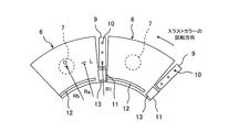
図1は、本実施形態におけるティルティングパッド式スラスト軸受の構造を表す軸方向断面図である。図2は、図1におけるII−II断面矢視図であって、本実施形態におけるパッドの構造を表す図である(便宜上、2つのパッドのみ示すものである)。図3は、本実施形態におけるパッドの摺動面上の油膜の圧力と潤滑油の流れを示す図である。 FIG. 1 is an axial sectional view showing a structure of a tilting pad type thrust bearing in the present embodiment. FIG. 2 is a sectional view taken along the line II-II in FIG. 1 and shows the structure of the pad in the present embodiment (for convenience, only two pads are shown). FIG. 3 is a diagram showing the pressure of the oil film on the sliding surface of the pad and the flow of lubricating oil in the present embodiment.
図1で示すように、回転軸1は、水平方向(図中左右方向)に延在するように設置されている。回転軸1の外周側には一対のスラストカラー2が固定されており、回転軸1とスラストカラー2が一体となって回転するようになっている。ティルティングパッド式スラスト軸受100は、一対のスラストカラー2を介して回転軸1の軸方向荷重を受けるように構成されている。
As shown in FIG. 1, the
スラスト軸受100は、ペデスタル3で固定された略円環状の軸受ハウジング4と、この軸受ハウジング4の内側で且つ軸方向一方側(図1中右側)及び他方側(図1中左側)にそれぞれ固定された略円環状の軸受ベース5と、一方側のスラストカラー2に対向するように一方側の軸受ベース5の周方向に沿って(言い換えれば、回転軸1の外周側に)配置された複数(本実施形態では8つ)のパッド6と、他方側のスラストカラー2に対向するように他方側の軸受ベース5の周方向に沿って(言い換えれば、回転軸1の外周側に)配置された複数(本実施形態では8つ)のパッド6とを備えている。パッド6は、その背面側(図1中左側)にピボット7が設けられており、このピボット7がピボット受8と接触している。これにより、パッド6が揺動可能に支持されている。
The
図2で示すように、複数のパッド6の間には、複数の給油管9が設けられている。各給油管9は、回転軸1の径方向に離間して形成された複数(本実施形態では3つ)の給油口10(ノズル孔)を有している。なお、給油管9は、パッド6の前端側かつ径方向内側に設けられた前端突出部11と干渉しないように、その径方向外側に配置されている。最外側の給油口10は、パッド6の幅方向中心L又は揺動中心(言い換えれば、ピボット7の中心)Oより径方向外側に位置している。最内側の給油口10は、パッド6の幅方向中心L又は揺動中心Oより径方向内側に位置している(すなわち、図中、R1<Ra<Rb)。
As shown in FIG. 2, a plurality of
給油管9は、軸受ハウジング4に形成された給油路(図示せず)等を介してポンプ(図示せず)に接続されている。ポンプで昇圧された潤滑油は、給油管9の給油口10からスラストカラー2に向けて噴出される。そして、スラストカラー2の回転に伴い、スラストカラー2とパッド6の摺動面(言い換えれば、スラストカラー2に対向する対向面)との間に流入する。このとき、パッド6が揺動し、パッド6の摺動面とスラストカラー2との隙間が回転方向に徐々に小さくなるので、くさび効果により動圧が発生し、油膜を形成する。図3中の二点鎖線は油膜圧力の等圧力線を示しているが、パッド6の揺動中心Oにて最大圧力となる圧力分布が生じる。この油膜により、スラストカラー2の回転(ひいては、回転軸1の回転)を阻害することなく、スラストカラー2を介して回転軸1の軸方向荷重を支持するようになっている。
The
ところで、給油管9の給油口10からパッド6の摺動面に供給された潤滑油は、上述した油膜圧力により、その一部がパッド6の外周側及び内周側に押し流される傾向にある。
By the way, a part of the lubricating oil supplied to the sliding surface of the
そこで、本実施形態では、パッド6の摺動面の内周縁の近傍(すなわち、パッド6の摺動面における幅方向中心Cよりも内周縁に近づけられた位置)に、周方向に延在するように流出案内溝12が形成されている。この流出案内溝12は、パッド6の摺動面及び後端面に開口している。また、流出案内溝12とは独立して、給油管9の給油口10より径方向内側に位置するように、パッド6の前端突出部11(言い換えれば、パッド6の摺動面の前縁部)に流入案内溝13が形成されている。この流入案内溝13は、パッド6の後端面における流出案内溝12の開口と同じ径方向位置を含む開口を形成するように、パッド6の前端面に開口している。また、流入案内溝13は、パッド6の摺動面における流出案内溝12の開口と同じ径方向位置より径方向外側の領域を含む開口を形成するように、パッド6の摺動面に開口している。
Therefore, in the present embodiment, it extends in the circumferential direction in the vicinity of the inner peripheral edge of the sliding surface of the pad 6 (that is, a position closer to the inner peripheral edge than the center C in the width direction on the sliding surface of the pad 6). Thus, the
これにより、潤滑油の流れは、図3中矢印a,b,c,d,eで示すようになる。具体的に説明すると、矢印aで示すように、パッド6の摺動面に供給された潤滑油の一部は、パッド6の外周側に押し流され、パッド6の外周端から流出する。矢印bで示すように、パッド6の摺動面に供給された潤滑油の一部は、パッド6の外周側に若干押し流されるものの、パッド6の後端から流出する。矢印cで示すように、パッド6の摺動面に供給された潤滑油の一部は、パッド6の内周側に若干押し流されるものの、パッド6の後端から流出する。矢印dで示すように、パッド6の摺動面に供給された潤滑油の一部は、パッド6の内周側に押し流されるものの、流出案内溝12を経由して、パッド6の後端から流出する。流出案内溝12から流出する潤滑油は、比較的低温である。そして、矢印eで示すように、上流側パッド6の流出案内溝12から流出した潤滑油は、下流側パッド6の流入案内溝13を経由して、下流側パッド6の摺動面に供給されるようになっている。
Thereby, the flow of the lubricating oil becomes as shown by arrows a, b, c, d, and e in FIG. More specifically, as indicated by an arrow a, part of the lubricating oil supplied to the sliding surface of the
本実施形態の作用効果を、図4及び図5を用いて説明する。図4は、従来技術(すなわち、流出案内溝12及び流入案内溝13を有しない場合)における給油量を説明するための図であり、図5は、本実施形態における給油量を説明するための図である。
The effect of this embodiment is demonstrated using FIG.4 and FIG.5. FIG. 4 is a diagram for explaining the oil supply amount in the prior art (that is, when the
従来技術においては、パッドの摺動面に供給された潤滑油は、パッドの後端からだけでなく、パッドの外周端及び内周端からも流出する。パッドの後端から流出した潤滑油は、一部がキャリーオーバとして下流側パッドに供給され、残りが軸受の外部へ排出される。図4中の斜線部分はキャリーオーバの油量であり、白抜部分は排油量Qtである。パッドの外周端から流出した潤滑油は、軸受の外部へ排出されており、排油量Qoである。パッドの内周端から流出した潤滑油は、軸受の外部へ排出されており、排油量Qi(但し、一般的に、Qi<Qo)である。したがって、全排油量(Qt+Qo+Qi)となるため、給油量(Qt+Qo+Qi)が必要となる。 In the prior art, the lubricating oil supplied to the sliding surface of the pad flows out not only from the rear end of the pad but also from the outer peripheral end and inner peripheral end of the pad. A part of the lubricating oil flowing out from the rear end of the pad is supplied to the downstream pad as a carry-over, and the rest is discharged to the outside of the bearing. The shaded portion in FIG. 4 is the carryover oil amount, and the white portion is the oil discharge amount Qt. The lubricating oil that has flowed out from the outer peripheral edge of the pad is discharged to the outside of the bearing, and has an oil discharge amount Qo. The lubricating oil that has flowed out from the inner peripheral edge of the pad is discharged to the outside of the bearing, and the amount of oil discharged Qi (however, generally Qi <Qo). Therefore, since the total oil drain amount (Qt + Qo + Qi) is obtained, the oil supply amount (Qt + Qo + Qi) is required.
一方、本実施形態においては、流出案内溝12によって、パッド6の内周端からの潤滑油の排出を抑止でき、さらに、その潤滑油を後端側(すなわち、下流側パッド6の前端側)に流出させることができる。そして、下流側パッド6の流入案内溝13によって、上流側パッド6の流出案内溝12から流出した比較的低温な潤滑油を、下流側パッド6の摺動面に供給することができる。したがって、パッド6の内周端からの排油量Qiを実質的になくすことができる。その結果、給油量を(Qt+Qo)に低減することができる。
On the other hand, in the present embodiment, the
本発明の第2の実施形態を、図6により説明する。図6は、本施形態におけるパッドの構造を表す図である。なお、本実施形態において、上記第1の実施形態と同等の部分は同一の符号を付し、適宜説明を省略する。 A second embodiment of the present invention will be described with reference to FIG. FIG. 6 is a diagram illustrating the structure of the pad in the present embodiment. Note that in this embodiment, the same parts as those in the first embodiment are denoted by the same reference numerals, and description thereof will be omitted as appropriate.
本実施形態では、給油管9Aは、パッド6Aの前端側かつ径方向外側に設けられた前端突出部14と干渉しないように、その径方向内側に配置されている。最内側の給油口10は、パッド6の幅方向中心L又は揺動中心Oより径方向内側に位置している。最外側の給油口10は、パッド6の幅方向中心L又は揺動中心Oより径方向外側に位置している(すなわち、図中、Ra<Rb<R2)。
In the present embodiment, the
そして、パッド6Aの摺動面の外周縁の近傍(すなわち、パッド6Aの摺動面における幅方向中心Cよりも外周縁に近づけられた位置)に、周方向に延在するように流出案内溝15が形成されている。この流出案内溝15は、パッド6Aの摺動面及び後端面に開口している。また、流出案内溝15とは独立して、給油管9Aの給油口10より径方向外側に位置するように、パッド6Aの前端突出部14(言い換えれば、パッド6Aの摺動面の前縁部)に流入案内溝16が形成されている。この流入案内溝16は、パッド6Aの後端面における流出案内溝15の開口と同じ径方向位置を含む開口を形成するように、パッド6Aの前端面に開口している。また、流入案内溝16は、パッド6Aの摺動面における流出案内溝15の開口と同じ径方向位置より径方向内側の領域を含む開口を形成するように、パッド6Aの摺動面に開口している。
The outflow guide groove extends in the vicinity of the outer peripheral edge of the sliding surface of the
これにより、パッド6Aの摺動面に供給された潤滑油の一部は、パッド6Aの外周側に押し流されるものの、流出案内溝15を経由して、パッド6Aの後端から流出する。流出案内溝15から流出する潤滑油は、比較的低温である。そして、上流側パッド6Aの流出案内溝15から流出した潤滑油は、下流側パッド6Aの流入案内溝16を経由して、下流側パッド6Aの摺動面に供給されるようになっている。
As a result, a part of the lubricating oil supplied to the sliding surface of the
このような本実施形態においては、流出案内溝15によって、パッド6Aの外周端からの潤滑油の排出を抑止でき、さらに、その潤滑油を後端側(すなわち、下流側パッド6Aの前端側)に流出させることができる。そして、下流側パッド6Aの流入案内溝16によって、上流側パッド6Aの流出案内溝15から流出した比較的低温な潤滑油を、下流側パッド6Aの摺動面に供給することができる。したがって、パッド6Aの外周端からの排油量Qoを実質的になくすことができる。その結果、給油量を(Qt+Qi)に低減することができる。
In such an embodiment, the
本発明の第3の実施形態を、図7により説明する。図7は、本施形態におけるパッドの構造を表す図である。なお、本実施形態において、上記第1及び第2の実施形態と同等の部分は同一の符号を付し、適宜説明を省略する。 A third embodiment of the present invention will be described with reference to FIG. FIG. 7 is a diagram showing the structure of the pad in the present embodiment. In the present embodiment, the same parts as those in the first and second embodiments are denoted by the same reference numerals, and description thereof will be omitted as appropriate.
本実施形態では、給油管9Bは、パッド6Bの前端突出部11,14と干渉しないように、それらの間に配置されている。外側の給油口10は、パッド6Bの幅方向中心又は揺動中心より径方向外側に位置し、内側の給油口10は、パッド6Bの幅方向中心又は揺動中心より径方向内側に位置している。
In the present embodiment, the
そして、パッド6Bの摺動面の内周縁の近傍に、周方向に延在するように流出案内溝12が形成されている。この流出案内溝12は、パッド6Bの摺動面及び後端面に開口している。また、流出案内溝12とは独立して、給油管9Bの給油口10より径方向内側に位置するように、パッド6Bの前端突出部11に流入案内溝13が形成されている。この流入案内溝13は、パッド6Bの後端面における流出案内溝12の開口と同じ径方向位置を含む開口を形成するように、パッド6Bの前端面に開口している。また、流入案内溝13は、パッド6Bの摺動面における流出案内溝12の開口と同じ径方向位置より径方向外側の領域を含む開口を形成するように、パッド6Bの摺動面に開口している。
An
これにより、パッド6Bの摺動面に供給された潤滑油の一部は、パッド6Bの内周側に押し流されるものの、流出案内溝12を経由して、パッド6Bの後端から流出する。流出案内溝12から流出する潤滑油は、比較的低温である。そして、上流側パッド6Bの流出案内溝12から流出した潤滑油は、下流側パッド6Bの流入案内溝13を経由して、下流側パッド6Bの摺動面に供給されるようになっている。
Thereby, a part of the lubricating oil supplied to the sliding surface of the
また、パッド6Bの摺動面の外周縁の近傍に、周方向に延在するように流出案内溝15が形成されている。この流出案内溝15は、パッド6Bの摺動面及び後端面に開口している。また、流出案内溝15とは独立して、給油管9Bの給油口10より径方向外側に位置するように、パッド6Bの前端突出部14に流入案内溝16が形成されている。この流入案内溝16は、パッド6Bの後端面における流出案内溝15の開口と同じ径方向位置を含む開口を形成するように、パッド6Bの前端面に開口している。また、流入案内溝16は、パッド6Bの摺動面における流出案内溝15の開口と同じ径方向位置より径方向内側の領域を含む開口を形成するように、パッド6Bの摺動面に開口している。
An
これにより、パッド6Bの摺動面に供給された潤滑油の一部は、パッド6Bの外周側に押し流されるものの、流出案内溝15を経由して、パッド6Bの後端から流出する。流出案内溝15から流出する潤滑油は、比較的低温である。そして、上流側パッド6Bの流出案内溝15から流出した潤滑油は、下流側パッド6Bの流入案内溝16を経由して、下流側パッド6Bの摺動面に供給されるようになっている。
As a result, a part of the lubricating oil supplied to the sliding surface of the
このような本実施形態においては、流出案内溝12,15によって、パッド6Bの内周端及び外周端からの潤滑油の排出を抑止でき、さらに、その潤滑油を後端側(すなわち、下流側パッド6Bの前端側)に流出させることができる。そして、下流側パッド6Bの流入案内溝13,16によって、上流側パッド6Bの流出案内溝12,15から流出した比較的低温な潤滑油を、下流側パッド6Bの摺動面に供給することができる。したがって、パッド6Bの内周端からの排油量Qi及び外周端からの排油量Qoを実質的になくすことができる。その結果、給油量をQtに低減することができる。
In this embodiment, the
なお、上記第1及び第3の実施形態においては、図示のように、流入案内溝13は、径方向内側の壁面が周方向に延在するように形成された場合を例にとり、上記第2及び第3の実施形態においては、図示のように、流入案内溝16は、径方向外側の壁面が周方向に延在するように形成された場合を例にとって説明したが、これに限られず、本発明の趣旨及び技術思想を逸脱しない範囲内で変形が可能である。すなわち、図8で示す第1の実施形態の一変形例及び図10で示す第3の実施形態の一変形例のように、パッド6の流入案内溝13Aは、径方向内側の壁面が周方向下流側に向かって径方向外側に傾斜するように形成されてもよい。あるいは、図9で示す第2の実施形態の一変形例及び図10で示す第3の実施形態の一変形例のように、パッド6Aの流入案内溝16Aは、径方向外側の壁面が周方向下流側に向かって径方向内側に傾斜するように形成されてもよい。これらの変形例においては、上記実施形態と比べ、流入案内溝からパッドの摺動面への供給量を増加させることができる。したがって、給油量をさらに低減することができる。
In the first and third embodiments, as shown in the drawing, the
また、上記第1〜第3の実施形態においては、複数のパッドの間に複数の給油管を設けた場合を例にとって説明したが、これに限られず、本発明の趣旨及び技術思想を逸脱しない範囲内で変形が可能である。すなわち、図11で示す第1の実施形態の他の変形例のように、パッド6Cの摺動面の前縁部で径方向外側に位置するように給油口17が形成されてもよい。この給油口17の径方向内側側壁は、パッド6Cの幅方向中心L又は揺動中心Oより径方向内側に位置している(すなわち、図中、R3<Ra<Rb)。そして、流入案内溝13は、給油口17より径方向内側に位置するように、パッド6Cの摺動面の前縁部に形成されればよい。あるいは、図12で示す第2の実施形態の他の変形例のように、パッド6Dの摺動面の前縁部で径方向内側に位置するように給油口17Aが形成されてもよい。この給油口17Aの径方向外側側壁は、パッド6Dの幅方向中心L又は揺動中心Oより径方向外側に位置している(すなわち、図中、Ra<Rb<R4)。そして、流入案内溝16は、給油口17Aより径方向外側に位置するように、パッド6Dの摺動面の前縁部に形成されればよい。あるいは、図13で示す第3の実施形態の他の変形例のように、パッド6Eの摺動面の前縁部で幅方向中央に位置するように給油口17Bが形成されてもよい。この給油口17Bの径方向内側側壁は、パッド6Eの幅方向中心又は揺動中心より径方向内側に位置し、径方向外側側壁は、パッド6Eの幅方向中心又は揺動中心より径方向外側に位置している。そして、流入案内溝13は、給油口17Bより径方向内側に位置するように、パッド6Eの摺動面の前縁部に形成されればよい。また、流入案内溝16は、給油口17Bより径方向外側に位置するように、パッド6Eの摺動面の前縁部に形成されればよい。これらの変形例においても、上記実施形態と同様の効果を得ることができる。
In the first to third embodiments, the case where a plurality of oil supply pipes are provided between a plurality of pads has been described as an example. However, the present invention is not limited to this and does not depart from the spirit and technical idea of the present invention. Variations are possible within the range. That is, as in another modification of the first embodiment shown in FIG. 11, the
次に、上述したティルティングパッド式スラスト軸受100を備えた回転機械の一例を、図14を用いて説明する。図14は、上述したティルティングパッド式スラスト軸受100を備えた蒸気タービンの構成を表す図である。
Next, an example of a rotating machine provided with the above-described tilting pad
図14で示すように、蒸気タービンは、蒸気圧力にそれぞれ対応した高圧タービン20、中圧タービン21、及び低圧タービン22で構成されており、これらタービン20,21,22と発電機23が回転軸1を介して連結されている。そして、回転軸1の径方向荷重を受ける複数のジャーナル軸受24と、回転軸1の軸方向荷重を受けるスラスト軸受100が設けられている。
As shown in FIG. 14, the steam turbine includes a high-
このような蒸気タービンにおいては、スラスト軸受100への給油量の低減により、給油のための補機や付属品(詳細には、ポンプや配管など)を小型化することができる。そのため、蒸気タービンのコンパクト化を図ることができる。
In such a steam turbine, by reducing the amount of oil supplied to the
なお、以上においては、回転軸1が水平方向に延在するように設置されており、ティルティングパッド式スラスト軸受100が一対のスラストカラー2を介して回転軸1の軸方向荷重を受けるような構成を例にとって説明したが、これに限られず、本発明の趣旨及び技術思想を逸脱しない範囲内で変形が可能である。すなわち、例えば、回転軸が鉛直方向に延在するように設置されており、ティルティングパッド式スラスト軸受が1つのスラストカラーを介して回転軸の軸方向荷重を受けるような構成であってもよい。この場合も、上記同様の効果を得ることができる。
In the above, the
1 回転軸
2 スラストカラー
6,6A,6B,6C,6D,6E パッド
10 給油口
12 流出案内溝
13,13A 流入案内溝
15 流出案内溝
16,16A 流入案内溝
17 給油口
100 ティルティングパッド式スラスト軸受
DESCRIPTION OF
Claims (11)
前記スラストカラーに対向するように前記回転軸の外周側に配置され、揺動可能に設けられた複数のパッドと、
前記複数のパッドの間若しくは前記複数のパッドの摺動面の前縁部に設けられた複数の給油口と、
前記パッドの摺動面における幅方向中心よりも内周縁に近づけられた位置で周方向に延在するように形成された流出案内溝と、
前記流出案内溝とは独立して、前記給油口より径方向内側に位置するように前記パッドの摺動面の前縁部に形成された流入案内溝とを有し、
前記流出案内溝は、前記パッドの摺動面及び後端面に開口し、
前記流入案内溝は、前記パッドの後端面における前記流出案内溝の開口と同じ径方向位置を含む開口を形成するように、前記パッドの前端面に開口し、且つ、前記パッドの摺動面における前記流出案内溝の開口と同じ径方向位置より径方向外側の領域を含む開口を形成するように、前記パッドの摺動面に開口したことを特徴とするティルティングパッド式スラスト軸受。 In the tilting pad type thrust bearing that receives the axial load of the rotating shaft through a thrust collar fixed to the outer peripheral side of the rotating shaft,
A plurality of pads arranged on the outer peripheral side of the rotating shaft so as to face the thrust collar and provided so as to be swingable;
A plurality of oil filler openings provided between the plurality of pads or at a front edge of a sliding surface of the plurality of pads;
An outflow guide groove formed to extend in the circumferential direction at a position closer to the inner peripheral edge than the center in the width direction on the sliding surface of the pad;
Inflow guide groove formed on the front edge portion of the sliding surface of the pad so as to be located radially inward from the oil filler port independently of the outflow guide groove,
The outflow guide groove opens on the sliding surface and rear end surface of the pad,
The inflow guide groove opens in the front end surface of the pad so as to form an opening including the same radial position as the opening of the outflow guide groove in the rear end surface of the pad, and in the sliding surface of the pad. A tilting pad type thrust bearing, wherein an opening is formed in the sliding surface of the pad so as to form an opening including a region radially outside the same radial position as the opening of the outflow guide groove.
前記流入案内溝より径方向外側に位置する前記給油口は、前記パッドの幅方向中心又は揺動中心より径方向外側だけでなく径方向内側にも配置されたことを特徴とするティルティングパッド式スラスト軸受。 The tilting pad type thrust bearing according to claim 1,
The tilting pad type is characterized in that the oil filler port located radially outward from the inflow guide groove is disposed not only radially outward but also radially inward from the width direction center or swing center of the pad. Thrust bearing.
前記流入案内溝は、径方向内側の壁面が周方向下流側に向かって径方向外側に傾斜するように形成されたことを特徴とするティルティングパッド式スラスト軸受。 The tilting pad type thrust bearing according to claim 1,
The tilting pad type thrust bearing, wherein the inflow guide groove is formed such that a radially inner wall surface is inclined radially outward toward a downstream side in the circumferential direction.
前記スラストカラーに対向するように前記回転軸の外周側に配置され、揺動可能に設けられた複数のパッドと、
前記複数のパッドの間若しくは前記複数のパッドの摺動面の前縁部に設けられた複数の給油口と、
前記パッドの摺動面における幅方向中心よりも外周縁に近づけられた位置で周方向に延在するように形成された流出案内溝と、
前記給油口より径方向外側に位置し、前記流出案内溝とは独立して前記パッドの摺動面の前縁部に形成された流入案内溝とを有し、
前記流出案内溝は、前記パッドの摺動面及び後端面に開口し、
前記流入案内溝は、前記パッドの後端面における前記流出案内溝の開口と同じ径方向位置を含む開口を形成するように、前記パッドの前端面に開口し、且つ、前記パッドの摺動面における前記流出案内溝の開口と同じ径方向位置より径方向内側の領域を含む開口を形成するように、前記パッドの摺動面に開口したことを特徴とするティルティングパッド式スラスト軸受。 In the tilting pad type thrust bearing that receives the axial load of the rotating shaft through a thrust collar fixed to the outer peripheral side of the rotating shaft,
A plurality of pads arranged on the outer peripheral side of the rotating shaft so as to face the thrust collar and provided so as to be swingable;
A plurality of oil filler openings provided between the plurality of pads or at a front edge of a sliding surface of the plurality of pads;
An outflow guide groove formed to extend in the circumferential direction at a position closer to the outer peripheral edge than the center in the width direction on the sliding surface of the pad;
An inflow guide groove that is located radially outward from the oil filler opening and that is formed on the front edge of the sliding surface of the pad independently of the outflow guide groove;
The outflow guide groove opens on the sliding surface and rear end surface of the pad,
The inflow guide groove opens in the front end surface of the pad so as to form an opening including the same radial position as the opening of the outflow guide groove in the rear end surface of the pad, and in the sliding surface of the pad. A tilting pad type thrust bearing, wherein an opening is formed in the sliding surface of the pad so as to form an opening including a region radially inward from the same radial position as the opening of the outflow guide groove.
前記流入案内溝より径方向内側に位置する前記給油口は、前記パッドの幅方向中心又は揺動中心より径方向内側だけでなく径方向外側にも配置されたことを特徴とするティルティングパッド式スラスト軸受。 The tilting pad type thrust bearing according to claim 4,
The tilting pad type, wherein the oil supply port located radially inward from the inflow guide groove is disposed not only radially inward but also radially outward from the center in the width direction or the swing center of the pad. Thrust bearing.
前記流入案内溝は、径方向外側の壁面が周方向下流側に向かって径方向内側に傾斜するように形成されたことを特徴とするティルティングパッド式スラスト軸受。 The tilting pad type thrust bearing according to claim 4,
The tilting pad type thrust bearing, wherein the inflow guide groove is formed such that a radially outer wall surface is inclined radially inward toward a circumferential downstream side.
前記スラストカラーに対向するように前記回転軸の外周側に配置され、揺動可能に設けられた複数のパッドと、
前記複数のパッドの間若しくは前記複数のパッドの摺動面の前縁部に設けられた複数の給油口と、
前記パッドの摺動面における幅方向中心よりも内周縁に近づけられた位置で周方向に延在するように形成された第1の流出案内溝と、
前記給油口より径方向内側に位置し、前記第1の流出案内溝とは独立して前記パッドの摺動面の前縁部に形成された第1の流入案内溝と、
前記パッドの摺動面における幅方向中心よりも外周縁に近づけられた位置で周方向に延在するように形成された第2の流出案内溝と、
前記給油口より径方向外側に位置し、前記第2の流出案内溝とは独立して前記パッドの摺動面の前縁部に形成された第2の流入案内溝とを有し、
前記第1の流出案内溝は、前記パッドの摺動面及び後端面に開口し、
前記第1の流入案内溝は、前記パッドの後端面における前記第1の流出案内溝の開口と同じ径方向位置を含む開口を形成するように、前記パッドの前端面に開口し、且つ、前記パッドの摺動面における前記第1の流出案内溝の開口と同じ径方向位置より径方向外側の領域を含む開口を形成するように、前記パッドの摺動面に開口し、
前記第2の流出案内溝は、前記パッドの摺動面及び後端面に開口し、
前記第2の流入案内溝は、前記パッドの後端面における前記第2の流出案内溝の開口と同じ径方向位置を含む開口を形成するように、前記パッドの前端面に開口し、且つ、前記パッドの摺動面における前記第2の流出案内溝の開口と同じ径方向位置より径方向内側の領域を含む開口を形成するように、前記パッドの摺動面に開口したことを特徴とするティルティングパッド式スラスト軸受。 In the tilting pad type thrust bearing that receives the axial load of the rotating shaft through a thrust collar fixed to the outer peripheral side of the rotating shaft,
A plurality of pads arranged on the outer peripheral side of the rotating shaft so as to face the thrust collar and provided so as to be swingable;
A plurality of oil filler openings provided between the plurality of pads or at a front edge of a sliding surface of the plurality of pads;
A first outflow guide groove formed to extend in the circumferential direction at a position closer to the inner peripheral edge than the center in the width direction on the sliding surface of the pad;
A first inflow guide groove which is located radially inward from the oil filler opening and which is formed on a front edge portion of the sliding surface of the pad independently of the first outflow guide groove;
A second outflow guide groove formed to extend in the circumferential direction at a position closer to the outer peripheral edge than the center in the width direction on the sliding surface of the pad;
A second inflow guide groove formed on the front edge of the sliding surface of the pad independently of the second outflow guide groove, located on the radially outer side from the oil filler opening;
The first outflow guide groove opens on a sliding surface and a rear end surface of the pad,
The first inflow guide groove opens at the front end surface of the pad so as to form an opening including the same radial position as the opening of the first outflow guide groove in the rear end surface of the pad, and Opening the sliding surface of the pad so as to form an opening including a region radially outside the same radial position as the opening of the first outflow guide groove on the sliding surface of the pad;
The second outflow guide groove opens on the sliding surface and rear end surface of the pad,
The second inflow guide groove opens at the front end surface of the pad so as to form an opening including the same radial position as the opening of the second outflow guide groove on the rear end surface of the pad, and A till having an opening on the sliding surface of the pad so as to form an opening including a region radially inward from the same radial position as the opening of the second outflow guide groove on the sliding surface of the pad. Ting pad type thrust bearing.
前記第1の流入案内溝より径方向外側に位置し、且つ前記第2の流入案内溝より径方向外側に位置する前記給油口は、前記パッドの幅方向中心又は揺動中心より径方向外側だけでなく径方向内側にも配置されたことを特徴とするティルティングパッド式スラスト軸受。 The tilting pad type thrust bearing according to claim 7,
The oil filler port located radially outward from the first inflow guide groove and radially outward from the second inflow guide groove is only radially outward from the width direction center or swing center of the pad. A tilting pad type thrust bearing characterized by being arranged not only in the radial direction but also in the radial direction.
前記第1の流入案内溝は、径方向内側の壁面が周方向下流側に向かって径方向外側に傾斜するように形成され、
前記第2の流入案内溝は、径方向外側の壁面が周方向下流側に向かって径方向内側に傾斜するように形成されたことを特徴とするティルティングパッド式スラスト軸受。 The tilting pad type thrust bearing according to claim 7,
The first inflow guide groove is formed such that a radially inner wall surface is inclined radially outward toward a circumferential downstream side,
The tilting pad thrust bearing, wherein the second inflow guide groove is formed such that a radially outer wall surface is inclined radially inward toward the circumferential downstream side.
Priority Applications (3)
| Application Number | Priority Date | Filing Date | Title |
|---|---|---|---|
| JP2013232028A JP6184299B2 (en) | 2013-11-08 | 2013-11-08 | Tilting pad type thrust bearing and rotating machine equipped with the same |
| US14/533,468 US9670957B2 (en) | 2013-11-08 | 2014-11-05 | Tilting-pad thrust bearing and rotary machine having the same |
| EP14192078.5A EP2878837B1 (en) | 2013-11-08 | 2014-11-06 | Tilting-pad thrust bearing and rotary machine having the same |
Applications Claiming Priority (1)
| Application Number | Priority Date | Filing Date | Title |
|---|---|---|---|
| JP2013232028A JP6184299B2 (en) | 2013-11-08 | 2013-11-08 | Tilting pad type thrust bearing and rotating machine equipped with the same |
Publications (3)
| Publication Number | Publication Date |
|---|---|
| JP2015094373A JP2015094373A (en) | 2015-05-18 |
| JP2015094373A5 JP2015094373A5 (en) | 2016-11-04 |
| JP6184299B2 true JP6184299B2 (en) | 2017-08-23 |
Family
ID=51903809
Family Applications (1)
| Application Number | Title | Priority Date | Filing Date |
|---|---|---|---|
| JP2013232028A Expired - Fee Related JP6184299B2 (en) | 2013-11-08 | 2013-11-08 | Tilting pad type thrust bearing and rotating machine equipped with the same |
Country Status (3)
| Country | Link |
|---|---|
| US (1) | US9670957B2 (en) |
| EP (1) | EP2878837B1 (en) |
| JP (1) | JP6184299B2 (en) |
Families Citing this family (12)
| Publication number | Priority date | Publication date | Assignee | Title |
|---|---|---|---|---|
| JP2018105467A (en) | 2016-12-28 | 2018-07-05 | 株式会社日立製作所 | Tilting pad type journal bearing |
| JP6990977B2 (en) | 2017-03-07 | 2022-01-12 | 大同メタル工業株式会社 | Sliding member |
| DE102017116786A1 (en) * | 2017-07-25 | 2019-01-31 | Zollern Bhw Gleitlager Gmbh & Co. Kg | Bearing arrangement for supporting a shaft of a transmission |
| CN107642542B (en) * | 2017-09-25 | 2024-01-09 | 台州七八一六船舶工业有限公司 | High-speed thrust sliding bearing |
| CN111771067B (en) * | 2018-03-15 | 2022-06-21 | 苏尔寿管理有限公司 | Bearing shell for tilt bearing shell thrust bearing assembly and thrust bearing assembly |
| JP7136734B2 (en) | 2019-03-28 | 2022-09-13 | 大同メタル工業株式会社 | sliding member |
| CN110552745A (en) * | 2019-09-23 | 2019-12-10 | 云南锡业股份有限公司铜业分公司 | Steam turbine thrust pad assembly and method for prolonging service life of thrust pad |
| JP7335179B2 (en) | 2020-02-06 | 2023-08-29 | 大同メタル工業株式会社 | sliding member |
| JP7335178B2 (en) * | 2020-02-06 | 2023-08-29 | 大同メタル工業株式会社 | sliding member |
| CN113775642B (en) * | 2021-09-15 | 2023-08-22 | 上海涟屹轴承科技有限公司 | Thrust bearing and rotating shaft |
| US20240068510A1 (en) * | 2022-08-31 | 2024-02-29 | Elliott Company | Tilt pad journal bearing with lubrication arrangement |
| CN116241553A (en) * | 2023-04-06 | 2023-06-09 | 浙江彰贵轴承科技有限公司 | Tilting pad thrust sliding bearing with adjustable fulcrum offset |
Family Cites Families (15)
| Publication number | Priority date | Publication date | Assignee | Title |
|---|---|---|---|---|
| JPS4967063A (en) * | 1972-11-10 | 1974-06-28 | ||
| US4077682A (en) * | 1976-08-24 | 1978-03-07 | Waukesha Bearings Corporation | Large thrust bearing with lubrication in the spaces between pads |
| DE3117746A1 (en) | 1981-05-05 | 1982-12-09 | Krupp Polysius Ag, 4720 Beckum | HYDRODYNAMIC RADIAL SLIDING BEARING |
| JPS594817U (en) * | 1982-07-01 | 1984-01-12 | 株式会社東芝 | Pad type journal bearing device |
| JPS5996422U (en) | 1982-12-20 | 1984-06-30 | 株式会社東芝 | Pad type thrust bearing device |
| JPS6295455U (en) * | 1985-12-02 | 1987-06-18 | ||
| JPH07113422A (en) * | 1993-10-15 | 1995-05-02 | Mitsubishi Heavy Ind Ltd | Tilting pad thrust bearing |
| JPH08145052A (en) * | 1994-11-24 | 1996-06-04 | Mitsubishi Heavy Ind Ltd | Dynamic pressure bearing |
| US5702186A (en) * | 1996-08-02 | 1997-12-30 | Westinghouse Electric Corporation | Journal bearing with leading edge groove vent |
| US6499883B2 (en) | 1997-03-31 | 2002-12-31 | Whm Holding Corporation | Tilting pad for bearings |
| JP2000356222A (en) * | 1999-06-14 | 2000-12-26 | Tokyo Electric Power Co Inc:The | Thrust bearing device |
| JP2012117608A (en) * | 2010-11-30 | 2012-06-21 | Mitsubishi Heavy Ind Ltd | Thrust bearing device |
| WO2013043495A1 (en) * | 2011-09-21 | 2013-03-28 | Dresser-Rand Company | Tilt pad bearing with through-pivot lubrication |
| JP5860172B2 (en) * | 2012-12-28 | 2016-02-16 | 株式会社日立製作所 | Combined bearing device |
| JP2015007463A (en) * | 2013-06-26 | 2015-01-15 | 三菱日立パワーシステムズ株式会社 | Tilting pad bearing |
-
2013
- 2013-11-08 JP JP2013232028A patent/JP6184299B2/en not_active Expired - Fee Related
-
2014
- 2014-11-05 US US14/533,468 patent/US9670957B2/en active Active
- 2014-11-06 EP EP14192078.5A patent/EP2878837B1/en not_active Not-in-force
Also Published As
| Publication number | Publication date |
|---|---|
| US9670957B2 (en) | 2017-06-06 |
| EP2878837A1 (en) | 2015-06-03 |
| EP2878837B1 (en) | 2016-04-27 |
| JP2015094373A (en) | 2015-05-18 |
| US20150132105A1 (en) | 2015-05-14 |
Similar Documents
| Publication | Publication Date | Title |
|---|---|---|
| JP6184299B2 (en) | Tilting pad type thrust bearing and rotating machine equipped with the same | |
| JP5416859B2 (en) | Tilting pad type journal bearing and rotating machine having the same | |
| JP6412788B2 (en) | Tilting pad bearing | |
| JP6312346B2 (en) | Journal bearing, rotating machine | |
| EP3032123B1 (en) | Tilting pad type journal bearing | |
| JP6038088B2 (en) | Bearings and bearing pads | |
| JP2015007463A (en) | Tilting pad bearing | |
| JP2008057346A (en) | Bearing for compressor | |
| JP2014202268A (en) | Bearing device and rotating machine | |
| JP2014119080A (en) | Slide bearing device | |
| JP2008151239A (en) | Tilting pad type bearing | |
| JP5860172B2 (en) | Combined bearing device | |
| KR102240987B1 (en) | Bearing device and rotating machine | |
| WO2019142383A1 (en) | Tilting pad bearing device and rotating machine | |
| JP2017026089A (en) | Tilting pad journal bearing | |
| JP2015028323A (en) | Steam turbine system and steam turbine power generation plant | |
| JP2010249200A (en) | Tilting pad bearing and rotary machine | |
| JP6798950B2 (en) | Tilting pad journal bearing equipment | |
| JP2017160861A (en) | Turbo machine | |
| JP2001132737A (en) | Bearing device and turbine | |
| JP7000010B2 (en) | Journal bearings and rotating machinery | |
| JP2017160860A (en) | Turbo machine | |
| JP2015218809A (en) | Journal bearing | |
| JP6399698B2 (en) | Bearing device, rotating machine | |
| JP2020016308A (en) | Tilting pad type journal bearing and rotary machine using the same |
Legal Events
| Date | Code | Title | Description |
|---|---|---|---|
| A521 | Request for written amendment filed |
Free format text: JAPANESE INTERMEDIATE CODE: A523 Effective date: 20160915 |
|
| A621 | Written request for application examination |
Free format text: JAPANESE INTERMEDIATE CODE: A621 Effective date: 20160915 |
|
| A977 | Report on retrieval |
Free format text: JAPANESE INTERMEDIATE CODE: A971007 Effective date: 20170623 |
|
| TRDD | Decision of grant or rejection written | ||
| A01 | Written decision to grant a patent or to grant a registration (utility model) |
Free format text: JAPANESE INTERMEDIATE CODE: A01 Effective date: 20170627 |
|
| A61 | First payment of annual fees (during grant procedure) |
Free format text: JAPANESE INTERMEDIATE CODE: A61 Effective date: 20170725 |
|
| R150 | Certificate of patent or registration of utility model |
Ref document number: 6184299 Country of ref document: JP Free format text: JAPANESE INTERMEDIATE CODE: R150 |
|
| R250 | Receipt of annual fees |
Free format text: JAPANESE INTERMEDIATE CODE: R250 |
|
| S533 | Written request for registration of change of name |
Free format text: JAPANESE INTERMEDIATE CODE: R313533 |
|
| R350 | Written notification of registration of transfer |
Free format text: JAPANESE INTERMEDIATE CODE: R350 |
|
| R250 | Receipt of annual fees |
Free format text: JAPANESE INTERMEDIATE CODE: R250 |
|
| LAPS | Cancellation because of no payment of annual fees |