EP3032123B1 - Tilting pad type journal bearing - Google Patents
Tilting pad type journal bearing Download PDFInfo
- Publication number
- EP3032123B1 EP3032123B1 EP15199290.6A EP15199290A EP3032123B1 EP 3032123 B1 EP3032123 B1 EP 3032123B1 EP 15199290 A EP15199290 A EP 15199290A EP 3032123 B1 EP3032123 B1 EP 3032123B1
- Authority
- EP
- European Patent Office
- Prior art keywords
- pad
- sliding surface
- oil
- nozzle
- journal bearing
- Prior art date
- Legal status (The legal status is an assumption and is not a legal conclusion. Google has not performed a legal analysis and makes no representation as to the accuracy of the status listed.)
- Active
Links
Images


Classifications
-
- F—MECHANICAL ENGINEERING; LIGHTING; HEATING; WEAPONS; BLASTING
- F16—ENGINEERING ELEMENTS AND UNITS; GENERAL MEASURES FOR PRODUCING AND MAINTAINING EFFECTIVE FUNCTIONING OF MACHINES OR INSTALLATIONS; THERMAL INSULATION IN GENERAL
- F16C—SHAFTS; FLEXIBLE SHAFTS; ELEMENTS OR CRANKSHAFT MECHANISMS; ROTARY BODIES OTHER THAN GEARING ELEMENTS; BEARINGS
- F16C17/00—Sliding-contact bearings for exclusively rotary movement
- F16C17/02—Sliding-contact bearings for exclusively rotary movement for radial load only
- F16C17/03—Sliding-contact bearings for exclusively rotary movement for radial load only with tiltably-supported segments, e.g. Michell bearings
-
- F—MECHANICAL ENGINEERING; LIGHTING; HEATING; WEAPONS; BLASTING
- F16—ENGINEERING ELEMENTS AND UNITS; GENERAL MEASURES FOR PRODUCING AND MAINTAINING EFFECTIVE FUNCTIONING OF MACHINES OR INSTALLATIONS; THERMAL INSULATION IN GENERAL
- F16C—SHAFTS; FLEXIBLE SHAFTS; ELEMENTS OR CRANKSHAFT MECHANISMS; ROTARY BODIES OTHER THAN GEARING ELEMENTS; BEARINGS
- F16C33/00—Parts of bearings; Special methods for making bearings or parts thereof
- F16C33/02—Parts of sliding-contact bearings
- F16C33/04—Brasses; Bushes; Linings
- F16C33/06—Sliding surface mainly made of metal
- F16C33/10—Construction relative to lubrication
- F16C33/1025—Construction relative to lubrication with liquid, e.g. oil, as lubricant
- F16C33/1045—Details of supply of the liquid to the bearing
-
- F—MECHANICAL ENGINEERING; LIGHTING; HEATING; WEAPONS; BLASTING
- F16—ENGINEERING ELEMENTS AND UNITS; GENERAL MEASURES FOR PRODUCING AND MAINTAINING EFFECTIVE FUNCTIONING OF MACHINES OR INSTALLATIONS; THERMAL INSULATION IN GENERAL
- F16C—SHAFTS; FLEXIBLE SHAFTS; ELEMENTS OR CRANKSHAFT MECHANISMS; ROTARY BODIES OTHER THAN GEARING ELEMENTS; BEARINGS
- F16C33/00—Parts of bearings; Special methods for making bearings or parts thereof
- F16C33/02—Parts of sliding-contact bearings
- F16C33/04—Brasses; Bushes; Linings
- F16C33/06—Sliding surface mainly made of metal
- F16C33/10—Construction relative to lubrication
- F16C33/1025—Construction relative to lubrication with liquid, e.g. oil, as lubricant
- F16C33/106—Details of distribution or circulation inside the bearings, e.g. details of the bearing surfaces to affect flow or pressure of the liquid
- F16C33/108—Details of distribution or circulation inside the bearings, e.g. details of the bearing surfaces to affect flow or pressure of the liquid with a plurality of elements forming the bearing surfaces, e.g. bearing pads
-
- F—MECHANICAL ENGINEERING; LIGHTING; HEATING; WEAPONS; BLASTING
- F16—ENGINEERING ELEMENTS AND UNITS; GENERAL MEASURES FOR PRODUCING AND MAINTAINING EFFECTIVE FUNCTIONING OF MACHINES OR INSTALLATIONS; THERMAL INSULATION IN GENERAL
- F16C—SHAFTS; FLEXIBLE SHAFTS; ELEMENTS OR CRANKSHAFT MECHANISMS; ROTARY BODIES OTHER THAN GEARING ELEMENTS; BEARINGS
- F16C33/00—Parts of bearings; Special methods for making bearings or parts thereof
- F16C33/02—Parts of sliding-contact bearings
- F16C33/04—Brasses; Bushes; Linings
- F16C33/06—Sliding surface mainly made of metal
- F16C33/10—Construction relative to lubrication
- F16C33/1025—Construction relative to lubrication with liquid, e.g. oil, as lubricant
- F16C33/106—Details of distribution or circulation inside the bearings, e.g. details of the bearing surfaces to affect flow or pressure of the liquid
- F16C33/1085—Channels or passages to recirculate the liquid in the bearing
-
- F—MECHANICAL ENGINEERING; LIGHTING; HEATING; WEAPONS; BLASTING
- F16—ENGINEERING ELEMENTS AND UNITS; GENERAL MEASURES FOR PRODUCING AND MAINTAINING EFFECTIVE FUNCTIONING OF MACHINES OR INSTALLATIONS; THERMAL INSULATION IN GENERAL
- F16C—SHAFTS; FLEXIBLE SHAFTS; ELEMENTS OR CRANKSHAFT MECHANISMS; ROTARY BODIES OTHER THAN GEARING ELEMENTS; BEARINGS
- F16C2300/00—Application independent of particular apparatuses
- F16C2300/30—Application independent of particular apparatuses related to direction with respect to gravity
- F16C2300/34—Vertical, e.g. bearings for supporting a vertical shaft
Definitions
- the present invention relates to a tilting pad type journal bearing.
- the slide bearing is a shaft bearing that supports a rotary shaft via a thin fluid film.
- the slide bearings have higher load bearing performance compared to rolling bearings and also excel in vibration damping properties and shock resistance. Therefore, the slide bearings are widely employed for industrial rotary machines (steam turbines, generators, gas turbines, compressors, etc.) required to have high reliability. Tilting pad type journal bearings, excelling in oscillation stability, are well known as a type of slide bearings used for these rotary machines.
- the tilting pad type journal bearing comprises a plurality of pads which are arranged along the periphery of a rotary shaft and a bearing housing which supports the pads in a tiltable manner via a plurality of pivots.
- Lubricating oil is supplied to the gaps between the peripheral surface of the rotary shaft and sliding surfaces of the pads to form oil films, and the rotary shaft is supported by the pressure of the oil films. Since the tilting angle of each pad changes according to the pressure distribution of the oil film, unstable oscillation such as the so-called "oil whip" can be suppressed.
- the tilting pad type journal bearings can be roughly classified into two types: the oil bath type and the direct oil supply type.
- the oil bath type the lubricating oil is supplied to the gaps between the peripheral surface of the rotary shaft and the sliding surfaces of the pads by increasing the sealability of the bearing chamber accommodating the pads and storing the lubricating oil in the bearing chamber.
- the direct oil supply type the lubricating oil is supplied to the gaps between the peripheral surface of the rotary shaft and the sliding surfaces of the pads via nozzles arranged between the pads, for example (see JP-2004-197890-A , for example).
- Patent document JP 2011 179609 A describes a tilting pad journal bearing including: a plurality of tilting pads provided in the circumferential direction of the outer peripheral surface of a rotating shaft and rotatably supporting the rotating shaft; and a pair of plates respectively disposed at spaces on both sides in the axial direction of the rotating shaft to the plurality of tilting pads. The spaces are set to be narrower on the downstream side than on the upstream side in the rotating direction of the rotating shaft.
- Patent Document EP2762735A1 describes a direct lubrication tilting pad journal bearing. In the direct lubrication tilting pad journal bearing, a pad has an oil collection path in a groove shape.
- the oil collection path is formed so that an inlet may open in an opposite end surface to a rotation direction of a rotation shaft in the pad, an outlet may open in an inner circumferential surface of the pad, and the inlet and the outlet may continuously open. Further, a width dimension of the oil collection path is smaller than a width dimension of the pad. Furthermore, a depth dimension from an outer circumferential surface of the rotation shaft to a bottom surface of the oil collection path is larger than a distance from the outer circumferential surface of the rotation shaft to an end of a nozzle.
- the sliding surface of each pad is formed so that its width in the axial direction is constant from the front edge (upstream end in the circumferential direction) to the rear edge (downstream end in the circumferential direction). Therefore, even though part of the lubricating oil supplied from the nozzle to a front edge part of the sliding surface of the pad flows towards a rear edge part of the sliding surface, the rest of the lubricating oil flows towards the side edges of the sliding surface and leaks out.
- the thickness of the oil film formed between the peripheral surface of the rotary shaft and the sliding surface of the pad decreases as it goes downstream in the circumferential direction. Therefore, if the width of the sliding surface of the pad in the axial direction is constant as mentioned above, the cross-sectional area of the oil film formed between the peripheral surface of the rotary shaft and the sliding surface of the pad (i.e., the cross-sectional area of the gap formed between the peripheral surface of the rotary shaft and the sliding surface of the pad) also decreases as it goes downstream in the circumferential direction.
- the amount of oil leakage via the side edges of the sliding surface of the pad is not small, and the amount of oil supplied from the nozzle has to be set greater in consideration of the amount of oil leakage.
- part of the lubricating oil after passing through the rear edge part of the sliding surface of the pad merges with the lubricating oil supplied from the nozzle and flows into the front edge part of the sliding surface of the next pad on the downstream side (carry-over). Therefore, the amount of oil that has to be supplied from the nozzle can be reduced if the amount of the carry-over oil is increased under a condition that the temperature rise of the sliding surface of the pad is relatively slight.
- the object of the present invention is to provide a tilting pad type journal bearing capable of reducing the amount of oil that has to be supplied to the bearing.
- the above object is achieved by a tilting pad type journal bearing according to claim 1.
- the sliding surface of each pad is formed so that its width increases as it goes from the front edge part towards the rear edge part (i.e., so that the width of the front edge part is small and the width of the rear edge part is large).
- the cross-sectional area of the oil film formed between the peripheral surface of the rotary shaft and the sliding surface of the pad does not decrease as it goes downstream in the circumferential direction, or the decrease can be suppressed. Accordingly, the amount of oil leakage via the side edges of the sliding surface of the pad can be decreased. Consequently, the amount of oil that has to be supplied from the nozzle can be reduced.
- the groove part formed in the tip end part of the nozzle induces the flow heading from the lateral parts towards the center in the width direction in the oil flow from the rear edge part of the sliding surface of the pad on the upstream side to the front edge part of the sliding surface of the pad on the downstream side. Accordingly, the ratio of the amount of the lubricating oil flowing into the front edge part of the sliding surface of the downstream pad while merging with the lubricating oil supplied from the nozzle to the amount of the lubricating oil flowing out from the rear edge part of the sliding surface of the upstream pad can be increased. In other words, the amount of the carry-over oil can be increased. Therefore, the amount of oil that has to be supplied from the nozzle can be reduced.
- the amount of oil that has to be supplied to the bearing can be reduced.
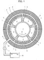
- Fig. 1 is a circumferential cross-sectional view showing the structure of a tilting pad type journal bearing according to a first embodiment of the present invention.
- Fig. 2A is a circumferential cross-sectional view showing a tilting state of a pad in this embodiment.
- Fig. 2B is a graph showing variations in the thickness of an oil film formed between the peripheral surface of the rotary shaft and a sliding surface of the pad in this embodiment.
- Fig. 3 is a perspective view showing the structure of the pad in this embodiment.
- Fig. 4 is a perspective view showing the structure of a nozzle in this embodiment.
- the tilting pad type journal bearing in this embodiment is a shaft bearing for supporting the radial-direction load of a rotary shaft 1 extending in the vertical direction, for example.
- the bearing comprises a plurality of (five in Fig. 1 ) pads 2 which are arranged along the periphery of the rotary shaft 1, a bearing housing 4 which supports the pads 2 in a tiltable (pivotable) manner via a plurality of (five in Fig. 1 ) pivots 3, and a plurality of (five in Fig. 1 ) nozzles 5 which are each arranged between the pads 2.
- an oil guide groove 6 is formed to extend circumferentially.
- the oil guide groove 6 of the bearing housing 4 is provided with a plurality of oil guide holes 7 penetrating the bearing housing 4 in the radial direction.
- the oil guide holes 7 are each connected to the nozzles 5.
- the oil guide groove 6 of the bearing housing 4 is connected to an oil tank 12 via an oil guide hole 9 of a casing 8, a pipe 10, and a pump 11.
- lubricating oil stored in the oil tank 12 is supplied to the oil guide groove 6 of the bearing housing 4, and further to the gap between the peripheral surface 13 of the rotary shaft 1 and the sliding surface 14 of each pad 2 via the oil guide hole 7 of the bearing housing 4 and the nozzles 5.
- the sliding surface 14 of the pad 2 is formed of metal having a low melting point (e.g., white metal) or resin.
- the lubricating oil supplied to the gap between the peripheral surface 13 of the rotary shaft 1 and the sliding surface 14 of each pad 2 rotates following the rotary shaft 1 and forms an oil film (unshown).
- the rotary shaft 1 is supported by the pressure of the oil film.
- each pad 2 tilts as shown in Fig. 2A depending on the pressure distribution in the oil film.
- the thickness of the oil film formed between the peripheral surface 13 of the rotary shaft 1 and the sliding surface 14 of each pad 2 decreases as it goes downstream in the circumferential direction (i.e., rotational direction of the rotary shaft 1 indicated by the arrow A in Figs. 1 and 2A ).
- the sliding surface 14 of the pad 2 has a width dimension W1 at the front edge and a greater width dimension W2 at the rear edge (W2 > W1).
- the sliding surface 14 is formed so that its width increases as it goes downstream in the circumferential direction from the front edge to the rear edge.
- Fig. 11 shows an example in which the sliding surface 14 is formed so that its width increases linearly, the width may also be increased differently (e.g. according to a curve).
- the nozzle 5 is formed of a round pipe 15 which is connected to the oil guide hole 7 of the bearing housing 4 and a hollow nozzle head 16 (tip end part) which is connected to the tip end of the round pipe 15.
- the nozzle head 16 has a width dimension W3 greater than the aforementioned width dimension W2 of the rear edge of the sliding surface 14 of the pad 2.
- a top surface (tip end surface) 17 of the nozzle head 16 has the width dimension W3.
- a groove part 18 is formed on the top surface 17 of the nozzle head 16.
- the groove part 18 has a substantially trapezoidal shape when viewed in the direction of the normal to the top surface 17.
- the width dimension of the front edge of the groove part 18 is W2, which equals the width dimension W2 of the rear edge of the sliding surface 14 of the pad 2
- the width dimension of the rear edge of the groove part 18 is W1, which equals the width dimension W1 of the front edge of the sliding surface 14 of the pad 2.
- a plurality of oil discharge ports 19 connecting to the inside of the nozzle head 16 and the round pipe 15 are formed. The oil discharged from these oil discharge ports 19 is supplied to the sliding surface 14 of the pad 2 arranged on the downstream side.
- a concavity 20 as an oil pool is formed around the oil discharge ports 19 (i.e., formed in a part of the groove part 18). With the concavity 20 formed as an oil pool, the oil can be supplied to the sliding surface 14 of the pad 2 even when the pump 11 stopped temporarily for some reason. However, the concavity 20 may also be left out as shown in Fig. 11 (explained later).
- Fig. 5 is a circumferential cross-sectional view showing the structure of a tilting pad type journal bearing as a first comparative example.
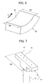
- Fig. 6 is a perspective view showing the structure of a pad in the first comparative example.
- Fig. 7 is a perspective view showing the structure of a nozzle in the first comparative example.
- Fig. 8 is a circumferential cross-sectional view showing the structure of a tilting pad type journal bearing as a second comparative example.
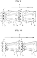
- Fig. 9 is a developed view showing the oil flow on the pad sliding surfaces and the nozzle top surfaces in the first comparative example.
- Fig. 10 is a developed view showing the oil flow on the pad sliding surfaces and the nozzle top surfaces in the second comparative example.
- Fig. 11 is a developed view showing the oil flow on the pad sliding surfaces and the nozzle top surfaces in this embodiment.
- the tilting pad type journal bearing as the first comparative example comprises a plurality of (five in Fig. 5 ) pads 30 and a plurality of (five in Fig. 5 ) nozzles 31 which are each arranged between the pads 30. As shown in Fig. 6 , a sliding surface 32 of each pad 30 is formed so that its width is constant (W2) from the front edge to the rear edge.
- the nozzle 31 is formed of a round pipe 15 and a hollow nozzle head 33 which is connected to the tip end of the round pipe 15.
- No groove part 18 is formed on the top surface 17 of the nozzle head 33.
- the top surface 17 of the nozzle head 33 is provided with a plurality of oil discharge ports 19.
- the width dimension of the nozzle head 33 (i.e., the width dimension of the top surface 17 of the nozzle head 33) is W3.
- the amount of oil leakage via the side edges of the sliding surface 32 of the pad 30 is not small, and the amount of oil supplied from the nozzle 31 has to be set greater in consideration of the amount of oil leakage.
- the tilting pad type journal bearing as the second comparative example comprises the pads 2 in the first embodiment instead of the pads 30.
- the sliding surface 14 of the pad 2 is formed so that its width increases as it goes downstream in the circumferential direction from the front edge to the rear edge.
- the cross-sectional area of the oil film does not decrease as it goes downstream in the circumferential direction, or the decrease can be suppressed. Accordingly, the amount of oil leakage via the side edges of the sliding surface 14 of the pad 2 can be reduced.
- most of the lubricating oil supplied from the nozzle 31 to the front edge part of the sliding surface 14 of the pad 2 flows towards the rear edge part of the sliding surface 14 as indicated by the arrows F1 in Fig. 10 . Therefore, the amount of oil that has to be supplied from the nozzle 31 can be reduced in comparison with the first comparative example.
- the tilting pad type journal bearing comprises the aforementioned nozzles 5 instead of the nozzles 31.
- the groove part 18 is formed on the top surface 17 of the nozzle 5.
- the groove part 18 induces a flow heading from lateral parts towards the center in the width direction (see arrows F5 in Fig. 11 ). Accordingly, the ratio of the amount of the lubricating oil flowing into the front edge part of the sliding surface 14 of the downstream pad 2 while merging with the lubricating oil supplied from the oil discharge ports 19 of the nozzle 5 (see arrows F6 in Fig.
- the amount of oil that has to be supplied to the bearing can be reduced in comparison with the first and second comparative examples.
- Fig. 12 is a circumferential cross-sectional view showing the structure of a tilting pad type journal bearing according to the second embodiment of the present invention. Elements in this embodiment equivalent to those in the above embodiment and comparative examples are assigned the already used reference characters and repeated explanation thereof is omitted properly.
- the tilting pad type journal bearing in this embodiment is a shaft bearing for supporting the radial-direction load of a rotary shaft 1 extending in a horizontal direction, for example.
- One of the pads 2 is arranged under (right under) the rotary shaft 1, and thus the load on the particular pad 2 is higher than that on each of the other pads 2.
- the temperature rise of the sliding surface 14 of the particular pad 2 situated under the rotary shaft 1 is greater in comparison with the sliding surfaces 14 of the other pads 2.
- the aforementioned nozzle 31 is arranged on the upstream side of the particular pad 2 situated under the rotary shaft 1, by which the amount of the carry-over oil for the particular pad 2 situated under the rotary shaft 1 is reduced and the temperature rise of the sliding surface 14 of the particular pad 2 is suppressed.
- the aforementioned nozzle 5 is arranged on the upstream side of each of the other pads 2, by which the amount of the carry-over oil for the other pads 2 is increased.
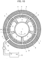
- Fig. 13 is a circumferential cross-sectional view showing the structure of a tilting pad type journal bearing according to the third embodiment of the present invention. Elements in this embodiment equivalent to those in the above embodiments and comparative examples are assigned the already used reference characters and repeated explanation thereof is omitted properly.
- the tilting pad type journal bearing in this embodiment is a shaft bearing for supporting the radial-direction load of a rotary shaft 1 extending in a horizontal direction, for example.
- One of the nozzles is arranged under (right under) the rotary shaft 1, and thus the load on each of two pads 2 situated upstream and downstream of the particular nozzle is higher than that on each of the other pads 2.
- the temperature rise of the sliding surfaces 14 of the two pads 2 upstream and downstream of the particular nozzle situated under the rotary shaft 1 is greater in comparison with the sliding surfaces 14 of the other pads 2.
- the aforementioned nozzle 31 is arranged under the rotary shaft 1 and another nozzle 31 is arranged at the position upstream of the former nozzle 31 across one pad 2, by which the amount of the carry-over oil for the two pads 2 upstream and downstream of the particular nozzle 31 situated under the rotary shaft 1 is reduced and the temperature rise of the sliding surfaces 14 of the two pads 2 is suppressed.
- the aforementioned nozzle 5 is arranged on the upstream side of each of the other pads 2, by which the amount of the carry-over oil for the other pads 2 is increased.
- the tilting pad type journal bearing comprises four of the nozzles 5 (i.e., the groove parts 18 are formed in the tip end parts of four nozzles) in the second embodiment and three of the nozzles 5 (i.e., the groove parts 18 are formed in the tip end parts of three nozzles) in the third embodiment, the number of the nozzles 5 is not limited to these examples. It is sufficient if the tilting pad type journal bearing comprises - at least one nozzle 5 (i.e., the groove part 18 is formed in the tip end part of at least one nozzle).
- the outline width dimension of the top surface 17 of the nozzle 5 (or 31) is greater than the width dimension W2 of the rear edge of the sliding surface 14 of the pad 2
- the outline width dimension of the top surface 17 of the nozzle 5 (or 31) may also;be set equal to the width dimension W2 of the rear edge of the sliding surface 14 of the pad 2.
- the configuration of the sliding surface 14 of the pad 2 is not limited to these examples.
- the front edge part of the sliding surface of the pad may be formed to have a constant width in the axial direction
- the rear edge part of the sliding surface of the pad e.g., a part from the circumferential-direction position ⁇ B where the oil film thickness hits the minimum to the rear edge, or a rear part of the sliding surface within 1/5 circumferential length of the sliding surface from the rear edge
- the amount of oil leakage via the side edges of the sliding surface of the pad can be decreased and the amount of oil that has to be supplied to the bearing can be reduced.
- a pad 2A may be configured to have a step surface 21 (specifically, a step surface 21 more recessed than the sliding surface 14 and forming no oil film between itself and the peripheral surface 13 of the rotary shaft 1) on each side of the sliding surface 14 in the axial direction.
- the pad 2A may also be configured so that its total width (including the sliding surface 14 and the step surfaces 21) in the axial direction is constant (W2) from the front edge (upstream end in the circumferential direction) to the rear edge (downstream end in the circumferential direction). Also in such a modification, the amount of oil that has to be supplied to the bearing can be reduced similarly to the above embodiments. Further, in this modification, the gap between each side face of the pad 2A and a wall surface facing the side face becomes narrower than those in the above embodiments. Therefore, mobility of the pad 2A in the axial direction decreases and mountability of the pad 2A is improved.
- Features, components and specific details of the structures of the above-described embodiments may be exchanged or combined to form further embodiments optimized for the respective application. As far as those modifications are apparent for an expert skilled in the art they shall be disclosed implicitly by the above description without specifying explicitly every possible combination.
Description
- The present invention relates to a tilting pad type journal bearing.
- The slide bearing is a shaft bearing that supports a rotary shaft via a thin fluid film. The slide bearings have higher load bearing performance compared to rolling bearings and also excel in vibration damping properties and shock resistance. Therefore, the slide bearings are widely employed for industrial rotary machines (steam turbines, generators, gas turbines, compressors, etc.) required to have high reliability. Tilting pad type journal bearings, excelling in oscillation stability, are well known as a type of slide bearings used for these rotary machines.
- The tilting pad type journal bearing comprises a plurality of pads which are arranged along the periphery of a rotary shaft and a bearing housing which supports the pads in a tiltable manner via a plurality of pivots. Lubricating oil is supplied to the gaps between the peripheral surface of the rotary shaft and sliding surfaces of the pads to form oil films, and the rotary shaft is supported by the pressure of the oil films. Since the tilting angle of each pad changes according to the pressure distribution of the oil film, unstable oscillation such as the so-called "oil whip" can be suppressed.
- The tilting pad type journal bearings can be roughly classified into two types: the oil bath type and the direct oil supply type. In the oil bath type, the lubricating oil is supplied to the gaps between the peripheral surface of the rotary shaft and the sliding surfaces of the pads by increasing the sealability of the bearing chamber accommodating the pads and storing the lubricating oil in the bearing chamber. In contrast, in the direct oil supply type, the lubricating oil is supplied to the gaps between the peripheral surface of the rotary shaft and the sliding surfaces of the pads via nozzles arranged between the pads, for example (see
JP-2004-197890-A
Patent documentJP 2011 179609 A
Patent DocumentEP2762735A1 describes a direct lubrication tilting pad journal bearing. In the direct lubrication tilting pad journal bearing, a pad has an oil collection path in a groove shape. The oil collection path is formed so that an inlet may open in an opposite end surface to a rotation direction of a rotation shaft in the pad, an outlet may open in an inner circumferential surface of the pad, and the inlet and the outlet may continuously open. Further, a width dimension of the oil collection path is smaller than a width dimension of the pad. Furthermore, a depth dimension from an outer circumferential surface of the rotation shaft to a bottom surface of the oil collection path is larger than a distance from the outer circumferential surface of the rotation shaft to an end of a nozzle. - In the tilting pad type journal bearing described in
JP-2004-197890-A - Further, in general, part of the lubricating oil after passing through the rear edge part of the sliding surface of the pad merges with the lubricating oil supplied from the nozzle and flows into the front edge part of the sliding surface of the next pad on the downstream side (carry-over). Therefore, the amount of oil that has to be supplied from the nozzle can be reduced if the amount of the carry-over oil is increased under a condition that the temperature rise of the sliding surface of the pad is relatively slight.
- The object of the present invention is to provide a tilting pad type journal bearing capable of reducing the amount of oil that has to be supplied to the bearing. The above object is achieved by a tilting pad type journal bearing according to
claim 1. - In the tilting pad type journal bearing according to the present invention, the sliding surface of each pad is formed so that its width increases as it goes from the front edge part towards the rear edge part (i.e., so that the width of the front edge part is small and the width of the rear edge part is large). With this configuration, the cross-sectional area of the oil film formed between the peripheral surface of the rotary shaft and the sliding surface of the pad does not decrease as it goes downstream in the circumferential direction, or the decrease can be suppressed. Accordingly, the amount of oil leakage via the side edges of the sliding surface of the pad can be decreased. Consequently, the amount of oil that has to be supplied from the nozzle can be reduced.
- Further, the groove part formed in the tip end part of the nozzle induces the flow heading from the lateral parts towards the center in the width direction in the oil flow from the rear edge part of the sliding surface of the pad on the upstream side to the front edge part of the sliding surface of the pad on the downstream side. Accordingly, the ratio of the amount of the lubricating oil flowing into the front edge part of the sliding surface of the downstream pad while merging with the lubricating oil supplied from the nozzle to the amount of the lubricating oil flowing out from the rear edge part of the sliding surface of the upstream pad can be increased. In other words, the amount of the carry-over oil can be increased. Therefore, the amount of oil that has to be supplied from the nozzle can be reduced.
- According to the present invention, the amount of oil that has to be supplied to the bearing can be reduced.
-
-
Fig. 1 is a circumferential cross-sectional view showing the structure of a tilting pad type journal bearing according to a first embodiment of the present invention. -
Fig. 2A is a circumferential cross-sectional view showing a tilting state of a pad in the first embodiment of the present invention. -
Fig. 2B is a graph showing variations in the thickness of an oil film formed between the peripheral surface of the rotary shaft and a sliding surface of the pad in the first embodiment of the present invention. -
Fig. 3 is a perspective view showing the structure of the pad in the first embodiment of the present invention. -
Fig. 4 is a perspective view showing the structure of a nozzle in the first embodiment of the present invention. -
Fig. 5 is a circumferential cross-sectional view showing the structure of a tilting pad type journal bearing as a first comparative example. -
Fig. 6 is a perspective view showing the structure of a pad in the first comparative example. -
Fig. 7 is a perspective view showing the structure of a nozzle in the first comparative example. -
Fig. 8 is a circumferential cross-sectional view showing the structure of a tilting pad type journal bearing as a second comparative example. -
Fig. 9 is a developed view showing the oil flow on the pad sliding surfaces and the nozzle top surfaces in the first comparative example. -
Fig. 10 is a developed view showing the oil flow on the pad sliding surfaces and the nozzle top surfaces in the second comparative example. -
Fig. 11 is a developed view showing the oil flow on the pad sliding surfaces and the nozzle top surfaces in the first embodiment of the present invention. -
Fig. 12 is a circumferential cross-sectional view showing the structure of a tilting pad type journal bearing according to a second embodiment of the present invention. -
Fig. 13 is a circumferential cross-sectional view showing the structure of a tilting pad type journal bearing according to a third embodiment of the present invention. -
Fig. 14 is a perspective view showing the structure of a pad in a modification according to the present invention. - A first embodiment of the present invention will be described below with reference to figures.
-
Fig. 1 is a circumferential cross-sectional view showing the structure of a tilting pad type journal bearing according to a first embodiment of the present invention.Fig. 2A is a circumferential cross-sectional view showing a tilting state of a pad in this embodiment.Fig. 2B is a graph showing variations in the thickness of an oil film formed between the peripheral surface of the rotary shaft and a sliding surface of the pad in this embodiment.Fig. 3 is a perspective view showing the structure of the pad in this embodiment.Fig. 4 is a perspective view showing the structure of a nozzle in this embodiment. - The tilting pad type journal bearing in this embodiment is a shaft bearing for supporting the radial-direction load of a
rotary shaft 1 extending in the vertical direction, for example. The bearing comprises a plurality of (five inFig. 1 )pads 2 which are arranged along the periphery of therotary shaft 1, a bearinghousing 4 which supports thepads 2 in a tiltable (pivotable) manner via a plurality of (five inFig. 1 ) pivots 3, and a plurality of (five inFig. 1 )nozzles 5 which are each arranged between thepads 2. - On the peripheral side of the bearing
housing 4, anoil guide groove 6 is formed to extend circumferentially. Theoil guide groove 6 of the bearinghousing 4 is provided with a plurality of oil guide holes 7 penetrating the bearinghousing 4 in the radial direction. The oil guide holes 7 are each connected to thenozzles 5. Theoil guide groove 6 of the bearinghousing 4 is connected to anoil tank 12 via anoil guide hole 9 of acasing 8, apipe 10, and apump 11. - By the driving the
pump 11, lubricating oil stored in theoil tank 12 is supplied to theoil guide groove 6 of the bearinghousing 4, and further to the gap between theperipheral surface 13 of therotary shaft 1 and the slidingsurface 14 of eachpad 2 via theoil guide hole 7 of the bearinghousing 4 and thenozzles 5. The slidingsurface 14 of thepad 2 is formed of metal having a low melting point (e.g., white metal) or resin. - The lubricating oil supplied to the gap between the
peripheral surface 13 of therotary shaft 1 and the slidingsurface 14 of eachpad 2 rotates following therotary shaft 1 and forms an oil film (unshown). Therotary shaft 1 is supported by the pressure of the oil film. In this case, eachpad 2 tilts as shown inFig. 2A depending on the pressure distribution in the oil film. Specifically, as shown inFig. 2B , the thickness of the oil film formed between theperipheral surface 13 of therotary shaft 1 and the slidingsurface 14 of eachpad 2 decreases as it goes downstream in the circumferential direction (i.e., rotational direction of therotary shaft 1 indicated by the arrow A inFigs. 1 and2A ). More specifically, the oil film thickness takes on the maximum value at the front edge (circumferential-direction position θ = 0) of the slidingsurface 14 of thepad 2, decreases as it goes downstream in the circumferential direction, and hits the minimum at a circumferential-direction position θB. Thereafter, the oil film thickness slightly increases as it goes towards the rear edge (circumferential-direction position θ = θA) of the slidingsurface 14. - As shown in
Fig. 3 , the slidingsurface 14 of thepad 2 has a width dimension W1 at the front edge and a greater width dimension W2 at the rear edge (W2 > W1). The slidingsurface 14 is formed so that its width increases as it goes downstream in the circumferential direction from the front edge to the rear edge. WhileFig. 11 (explained later) shows an example in which the slidingsurface 14 is formed so that its width increases linearly, the width may also be increased differently (e.g. according to a curve). - As shown in
Fig. 4 , thenozzle 5 is formed of around pipe 15 which is connected to theoil guide hole 7 of the bearinghousing 4 and a hollow nozzle head 16 (tip end part) which is connected to the tip end of theround pipe 15. Thenozzle head 16 has a width dimension W3 greater than the aforementioned width dimension W2 of the rear edge of the slidingsurface 14 of thepad 2. Thus, a top surface (tip end surface) 17 of thenozzle head 16 has the width dimension W3. - A
groove part 18 is formed on thetop surface 17 of thenozzle head 16. Thegroove part 18 has a substantially trapezoidal shape when viewed in the direction of the normal to thetop surface 17. In this embodiment, the width dimension of the front edge of thegroove part 18 is W2, which equals the width dimension W2 of the rear edge of the slidingsurface 14 of thepad 2, and the width dimension of the rear edge of thegroove part 18 is W1, which equals the width dimension W1 of the front edge of the slidingsurface 14 of thepad 2. At the bottom of thegroove part 18, a plurality ofoil discharge ports 19 connecting to the inside of thenozzle head 16 and theround pipe 15 are formed. The oil discharged from theseoil discharge ports 19 is supplied to the slidingsurface 14 of thepad 2 arranged on the downstream side. - A
concavity 20 as an oil pool is formed around the oil discharge ports 19 (i.e., formed in a part of the groove part 18). With theconcavity 20 formed as an oil pool, the oil can be supplied to the slidingsurface 14 of thepad 2 even when thepump 11 stopped temporarily for some reason. However, theconcavity 20 may also be left out as shown inFig. 11 (explained later). - Next, the effects of this embodiment will be explained below by using comparative examples.
-
Fig. 5 is a circumferential cross-sectional view showing the structure of a tilting pad type journal bearing as a first comparative example.Fig. 6 is a perspective view showing the structure of a pad in the first comparative example.Fig. 7 is a perspective view showing the structure of a nozzle in the first comparative example.Fig. 8 is a circumferential cross-sectional view showing the structure of a tilting pad type journal bearing as a second comparative example.Fig. 9 is a developed view showing the oil flow on the pad sliding surfaces and the nozzle top surfaces in the first comparative example.Fig. 10 is a developed view showing the oil flow on the pad sliding surfaces and the nozzle top surfaces in the second comparative example.Fig. 11 is a developed view showing the oil flow on the pad sliding surfaces and the nozzle top surfaces in this embodiment. Elements in the first and second comparative examples equivalent to those in the first embodiment are assigned the already used reference characters and repeated explanation thereof is omitted properly. - The tilting pad type journal bearing as the first comparative example comprises a plurality of (five in
Fig. 5 )pads 30 and a plurality of (five inFig. 5 )nozzles 31 which are each arranged between thepads 30. As shown inFig. 6 , a slidingsurface 32 of eachpad 30 is formed so that its width is constant (W2) from the front edge to the rear edge. - As shown in
Fig. 7 , thenozzle 31 is formed of around pipe 15 and ahollow nozzle head 33 which is connected to the tip end of theround pipe 15. Nogroove part 18 is formed on thetop surface 17 of thenozzle head 33. Thetop surface 17 of thenozzle head 33 is provided with a plurality ofoil discharge ports 19. The width dimension of the nozzle head 33 (i.e., the width dimension of thetop surface 17 of the nozzle head 33) is W3. - Part of the lubricating oil supplied from the
nozzle 31 to a front edge part of the slidingsurface 32 of thepad 30 flows towards a rear edge part of the slidingsurface 32 as indicated by the arrows F1 inFig. 9 , while the remaining lubricating oil flows towards the side edges of the slidingsurface 32 and leaks out as indicated by the arrows F2 inFig. 9 . More specifically, since the oil film thickness decreases as it goes downstream in the circumferential direction as shown in the aforementionedFigs. 2A and 2B , the cross-sectional area of the oil film also decreases as it goes downstream in the circumferential direction. The oil leaks out via the side edges of the slidingsurface 32 of thepad 30 in an amount corresponding to the decrease in the cross-sectional area of the oil film. Thus, the amount of oil leakage via the side edges of the slidingsurface 32 of thepad 30 is not small, and the amount of oil supplied from thenozzle 31 has to be set greater in consideration of the amount of oil leakage. - The tilting pad type journal bearing as the second comparative example comprises the
pads 2 in the first embodiment instead of thepads 30. As mentioned above, the slidingsurface 14 of thepad 2 is formed so that its width increases as it goes downstream in the circumferential direction from the front edge to the rear edge. With this configuration, the cross-sectional area of the oil film does not decrease as it goes downstream in the circumferential direction, or the decrease can be suppressed. Accordingly, the amount of oil leakage via the side edges of the slidingsurface 14 of thepad 2 can be reduced. In other words, most of the lubricating oil supplied from thenozzle 31 to the front edge part of the slidingsurface 14 of thepad 2 flows towards the rear edge part of the slidingsurface 14 as indicated by the arrows F1 inFig. 10 . Therefore, the amount of oil that has to be supplied from thenozzle 31 can be reduced in comparison with the first comparative example. - In the second comparative example, however, in the total amount of lubricating oil flowing out from the rear edge part of the sliding
surface 14 of thepad 2 on the upstream side (see arrows F3 inFig. 10 ), the ratio of the amount of lubricating oil flowing into the front edge part of the slidingsurface 14 of thepad 2 on the downstream side while merging with lubricating oil supplied from theoil discharge ports 19 of the nozzle 31 (see arrows F4 inFig. 10 ) decreases. In other words, the amount of the carry-over oil decreases. - The tilting pad type journal bearing according to this embodiment comprises the
aforementioned nozzles 5 instead of thenozzles 31. As mentioned above, thegroove part 18 is formed on thetop surface 17 of thenozzle 5. In the oil flow from the rear edge part of the slidingsurface 14 of theupstream pad 2 to the front edge part of the slidingsurface 14 of thedownstream pad 2, thegroove part 18 induces a flow heading from lateral parts towards the center in the width direction (see arrows F5 inFig. 11 ). Accordingly, the ratio of the amount of the lubricating oil flowing into the front edge part of the slidingsurface 14 of thedownstream pad 2 while merging with the lubricating oil supplied from theoil discharge ports 19 of the nozzle 5 (see arrows F6 inFig. 11 ) to the amount of the lubricating oil flowing out from the rear edge part of the slidingsurface 14 of the upstream pad 2 (see arrows F5 inFig. 11 ) can be increased. In other words, the amount of the carry-over oil can be increased. Therefore, the amount of oil that has to be supplied from thenozzle 5 can be reduced. - As described above, according to this embodiment, the amount of oil that has to be supplied to the bearing can be reduced in comparison with the first and second comparative examples.
- A second embodiment of the present invention will be described below with reference to
Fig. 12. Fig. 12 is a circumferential cross-sectional view showing the structure of a tilting pad type journal bearing according to the second embodiment of the present invention. Elements in this embodiment equivalent to those in the above embodiment and comparative examples are assigned the already used reference characters and repeated explanation thereof is omitted properly. - The tilting pad type journal bearing in this embodiment is a shaft bearing for supporting the radial-direction load of a
rotary shaft 1 extending in a horizontal direction, for example. One of thepads 2 is arranged under (right under) therotary shaft 1, and thus the load on theparticular pad 2 is higher than that on each of theother pads 2. Put another way, the temperature rise of the slidingsurface 14 of theparticular pad 2 situated under therotary shaft 1 is greater in comparison with the slidingsurfaces 14 of theother pads 2. - Therefore, in this embodiment, the
aforementioned nozzle 31 is arranged on the upstream side of theparticular pad 2 situated under therotary shaft 1, by which the amount of the carry-over oil for theparticular pad 2 situated under therotary shaft 1 is reduced and the temperature rise of the slidingsurface 14 of theparticular pad 2 is suppressed. On the other hand, theaforementioned nozzle 5 is arranged on the upstream side of each of theother pads 2, by which the amount of the carry-over oil for theother pads 2 is increased. Thus, also in this embodiment, the amount of oil that has to be supplied to the bearing can be reduced in comparison with the aforementioned first and second comparative examples. - A third embodiment of the present invention will be described below with reference to
Fig. 13. Fig. 13 is a circumferential cross-sectional view showing the structure of a tilting pad type journal bearing according to the third embodiment of the present invention. Elements in this embodiment equivalent to those in the above embodiments and comparative examples are assigned the already used reference characters and repeated explanation thereof is omitted properly. - The tilting pad type journal bearing in this embodiment is a shaft bearing for supporting the radial-direction load of a
rotary shaft 1 extending in a horizontal direction, for example. One of the nozzles is arranged under (right under) therotary shaft 1, and thus the load on each of twopads 2 situated upstream and downstream of the particular nozzle is higher than that on each of theother pads 2. Put another way, the temperature rise of the slidingsurfaces 14 of the twopads 2 upstream and downstream of the particular nozzle situated under therotary shaft 1 is greater in comparison with the slidingsurfaces 14 of theother pads 2. - Therefore, in this embodiment, the
aforementioned nozzle 31 is arranged under therotary shaft 1 and anothernozzle 31 is arranged at the position upstream of theformer nozzle 31 across onepad 2, by which the amount of the carry-over oil for the twopads 2 upstream and downstream of theparticular nozzle 31 situated under therotary shaft 1 is reduced and the temperature rise of the slidingsurfaces 14 of the twopads 2 is suppressed. On the other hand, theaforementioned nozzle 5 is arranged on the upstream side of each of theother pads 2, by which the amount of the carry-over oil for theother pads 2 is increased. Thus, also in this embodiment, the amount of oil that has to be supplied to the bearing can be reduced in comparison with the aforementioned first and second comparative examples. - Although not particularly mentioned in the above second and third embodiments, it is also possible to increase the number and/or the diameter of the
oil discharge ports 19 of thenozzle 31 in comparison with theoil discharge ports 19 of thenozzle 5. - While the above description of the embodiments has been given assuming, for example, that the tilting pad type journal bearing comprises four of the nozzles 5 (i.e., the
groove parts 18 are formed in the tip end parts of four nozzles) in the second embodiment and three of the nozzles 5 (i.e., thegroove parts 18 are formed in the tip end parts of three nozzles) in the third embodiment, the number of thenozzles 5 is not limited to these examples. It is sufficient if the tilting pad type journal bearing comprises - at least one nozzle 5 (i.e., thegroove part 18 is formed in the tip end part of at least one nozzle). - While the above description of the first through third embodiments has been given by using examples in which the outline width dimension of the
top surface 17 of the nozzle 5 (or 31) is greater than the width dimension W2 of the rear edge of the slidingsurface 14 of thepad 2, the outline width dimension of thetop surface 17 of the nozzle 5 (or 31) may also;be set equal to the width dimension W2 of the rear edge of the slidingsurface 14 of thepad 2. - While the above description of the first through third embodiments has been given by using examples in which the sliding
surface 14 of thepad 2 is formed so that its width in the axial direction increases as it goes downstream in the circumferential direction from the front edge to the rear edge (i.e., the front edge part and the rear edge part are also formed so that its width in the axial direction increases as it goes downstream in the circumferential direction) as shown inFigs. 3 and11 , the configuration of the slidingsurface 14 of thepad 2 is not limited to these examples. For example, the front edge part of the sliding surface of the pad (e.g., front part of the sliding surface within 1/5 circumferential length of the sliding surface from the front edge) may be formed to have a constant width in the axial direction, or the rear edge part of the sliding surface of the pad (e.g., a part from the circumferential-direction position θB where the oil film thickness hits the minimum to the rear edge, or a rear part of the sliding surface within 1/5 circumferential length of the sliding surface from the rear edge) may be formed to have a constant width in the axial direction. Also in these modifications, the amount of oil leakage via the side edges of the sliding surface of the pad can be decreased and the amount of oil that has to be supplied to the bearing can be reduced. - While the above description of the first through third embodiments has been given by using examples in which the
pad 2 is formed so that its total width in the axial direction increases as it goes downstream in the circumferential direction from the front edge (upstream end in the circumferential direction) to the rear edge (downstream end in the circumferential direction), the configuration of thepad 2 is not limited to these examples. For example, as shown inFig. 14 , apad 2A may be configured to have a step surface 21 (specifically, astep surface 21 more recessed than the slidingsurface 14 and forming no oil film between itself and theperipheral surface 13 of the rotary shaft 1) on each side of the slidingsurface 14 in the axial direction. Thepad 2A may also be configured so that its total width (including the slidingsurface 14 and the step surfaces 21) in the axial direction is constant (W2) from the front edge (upstream end in the circumferential direction) to the rear edge (downstream end in the circumferential direction). Also in such a modification, the amount of oil that has to be supplied to the bearing can be reduced similarly to the above embodiments. Further, in this modification, the gap between each side face of thepad 2A and a wall surface facing the side face becomes narrower than those in the above embodiments. Therefore, mobility of thepad 2A in the axial direction decreases and mountability of thepad 2A is improved.
Features, components and specific details of the structures of the above-described embodiments may be exchanged or combined to form further embodiments optimized for the respective application. As far as those modifications are apparent for an expert skilled in the art they shall be disclosed implicitly by the above description without specifying explicitly every possible combination.
Claims (6)
- A tilting pad type journal bearing comprising:a plurality of pads (2; 2A) which are arranged along the periphery of a rotary shaft (1);a bearing housing (4) which supports the pads (2; 2A) in a tiltable manner via a plurality of pivots (3); anda plurality of nozzles (5; 31) which are each arranged between the pads (2; 2A) to supply lubricating oil to sliding surfaces (14) of the pads (2; 2A),characterized in that:the sliding surface (14) of each of the pads (2; 2A) is formed so that the width of the sliding surface (14) increases as it goes from a front edge part towards a rear edge part of the sliding surface (14), anda tip end part (16) of at least one (5) of the nozzles has a groove part (18) formed on a top surface (17) of the tip end part (16) and the groove part (18) has a trapezoidal shape when viewed in the direction of the normal to the top surface (17), whereinthe width dimension of the front edge of the groove part (18) is equal to the width dimension (W2) of the rear edge of the sliding surface (14) of the pad (2), and
the width dimension of the rear edge of the groove part (18) is equal to the width dimension (W1) of the front edge of sliding surface (14) of the pad (2), thereby inducing a flow heading from lateral parts towards the center in the width direction, in an oil flow from the rear edge part of the sliding surface (14) of an upstream pad (2; 2A) to the front edge part of the sliding surface (14) of a downstream pad (2; 2A). - The tilting pad type journal bearing according to claim 1, wherein:
the top surface (17) has an outline width dimension that is greater than or equal to the width dimension of the rear edge part of the sliding surface (14) of the pad (2; 2A). - The tilting pad type journal bearing according to claim 2, wherein:each nozzle (31) not having the groove part (18) includes at least one oil discharge port (19) formed on the top surface (17), andeach nozzle (5) having the groove part (18) includes at least one oil discharge port (19) formed at the bottom of the groove part (18).
- The tilting pad type journal bearing according to claim 1 or 2, wherein:the rotary shaft (1) extends in a horizontal direction, andthe groove part (18) is formed on at least one (5) of the nozzles excluding a nozzle (31) on the upstream side of a pad (2; 2A) situated under the rotary shaft (1).
- The tilting pad type journal bearing according to claim 1 or 2, wherein:the rotary shaft (1) extends in a horizontal direction, andthe groove part (18) is formed on at least one (5) of the nozzles excluding a nozzle (31) situated under the rotary shaft (1) and a nozzle (31) situated upstream of the former nozzle (31) across a pad (2; 2A).
- The tilting pad type journal bearing according to at least one of the claims 1-5, wherein:
the pad (2A) is configured so that the total width of the entire pad including the sliding surface (14) and step surfaces (21) is constant from its front edge to its rear edge.
Applications Claiming Priority (1)
| Application Number | Priority Date | Filing Date | Title |
|---|---|---|---|
| JP2014249781A JP6426993B2 (en) | 2014-12-10 | 2014-12-10 | Tilting pad type journal bearing |
Publications (2)
| Publication Number | Publication Date |
|---|---|
| EP3032123A1 EP3032123A1 (en) | 2016-06-15 |
| EP3032123B1 true EP3032123B1 (en) | 2020-02-12 |
Family
ID=54848466
Family Applications (1)
| Application Number | Title | Priority Date | Filing Date |
|---|---|---|---|
| EP15199290.6A Active EP3032123B1 (en) | 2014-12-10 | 2015-12-10 | Tilting pad type journal bearing |
Country Status (4)
| Country | Link |
|---|---|
| US (1) | US9746024B2 (en) |
| EP (1) | EP3032123B1 (en) |
| JP (1) | JP6426993B2 (en) |
| CN (1) | CN105697537B (en) |
Families Citing this family (8)
| Publication number | Priority date | Publication date | Assignee | Title |
|---|---|---|---|---|
| DE102013209199A1 (en) * | 2013-05-17 | 2014-11-20 | Voith Patent Gmbh | Tilting segment and radial plain bearings |
| CN106151273B (en) * | 2016-07-08 | 2018-07-20 | 山东大学 | A kind of active control flexible hinge tilting-pad bearing |
| US11035404B2 (en) * | 2016-08-10 | 2021-06-15 | Mitsubishi Power, Ltd. | Bearing device and rotary machine |
| JP2018105467A (en) * | 2016-12-28 | 2018-07-05 | 株式会社日立製作所 | Tilting pad type journal bearing |
| JP6867027B2 (en) * | 2017-09-19 | 2021-04-28 | 京楽産業.株式会社 | Pachinko machine |
| JP6745292B2 (en) * | 2018-03-09 | 2020-08-26 | 三菱重工業株式会社 | Pad bearings, rotating machinery |
| JP7231437B2 (en) | 2019-02-20 | 2023-03-01 | 三菱重工業株式会社 | Oil bath type bearing device and rotating machine |
| US20240068510A1 (en) * | 2022-08-31 | 2024-02-29 | Elliott Company | Tilt pad journal bearing with lubrication arrangement |
Family Cites Families (13)
| Publication number | Priority date | Publication date | Assignee | Title |
|---|---|---|---|---|
| US3339990A (en) * | 1964-07-13 | 1967-09-05 | Worthington Corp | Lubricated bearing shoe |
| US3604767A (en) * | 1969-10-06 | 1971-09-14 | Cincinnati Milacron Inc | Adjustable pivoted shoe bearing and method of adjusting |
| JP3637187B2 (en) * | 1997-10-20 | 2005-04-13 | 三菱重工業株式会社 | Journal bearing |
| JP2000274432A (en) * | 1999-03-19 | 2000-10-03 | Toshiba Corp | Pad type journal bearing |
| US6739756B2 (en) * | 2001-03-12 | 2004-05-25 | Whm Holding Corporation | Combination thrust bearing and journal bearing, and method for distributing fluid to same |
| JP2004197890A (en) | 2002-12-20 | 2004-07-15 | Hitachi Ltd | Tilting pad bearing device |
| US7237957B2 (en) * | 2005-02-28 | 2007-07-03 | Kingsbury, Inc. | Journal bearing having self-retaining shoes and method of using the same to support a rotating shaft |
| CN101761546A (en) * | 2009-11-04 | 2010-06-30 | 西安交通大学 | Combined radial sliding bearing with tilting pad and fixed pad |
| JP5370215B2 (en) * | 2010-03-02 | 2013-12-18 | 株式会社Ihi | Tilting pad journal bearing |
| CN101793292B (en) * | 2010-03-30 | 2012-10-10 | 申科滑动轴承股份有限公司 | Direct-lubricating wide oil inlet nozzle for tilting pad bearing |
| WO2012114445A1 (en) * | 2011-02-21 | 2012-08-30 | 株式会社日立製作所 | Tilting pad journal bearing and rotary machine equipped with same |
| EP2762735A1 (en) * | 2011-09-29 | 2014-08-06 | Hitachi, Ltd. | Direct lubrication-type tilting pad journal bearing |
| JP2015007463A (en) | 2013-06-26 | 2015-01-15 | 三菱日立パワーシステムズ株式会社 | Tilting pad bearing |
-
2014
- 2014-12-10 JP JP2014249781A patent/JP6426993B2/en not_active Expired - Fee Related
-
2015
- 2015-12-08 US US14/961,981 patent/US9746024B2/en active Active
- 2015-12-08 CN CN201510896769.0A patent/CN105697537B/en not_active Expired - Fee Related
- 2015-12-10 EP EP15199290.6A patent/EP3032123B1/en active Active
Non-Patent Citations (1)
| Title |
|---|
| None * |
Also Published As
| Publication number | Publication date |
|---|---|
| US9746024B2 (en) | 2017-08-29 |
| US20160169274A1 (en) | 2016-06-16 |
| EP3032123A1 (en) | 2016-06-15 |
| CN105697537A (en) | 2016-06-22 |
| JP2016109268A (en) | 2016-06-20 |
| JP6426993B2 (en) | 2018-11-21 |
| CN105697537B (en) | 2018-03-27 |
Similar Documents
| Publication | Publication Date | Title |
|---|---|---|
| EP3032123B1 (en) | Tilting pad type journal bearing | |
| US9169866B2 (en) | Tilting pad bearing | |
| JP6412788B2 (en) | Tilting pad bearing | |
| JP6184299B2 (en) | Tilting pad type thrust bearing and rotating machine equipped with the same | |
| JP6325915B2 (en) | Tilting pad type journal bearing | |
| JP2009257445A (en) | Tilting pad thrust bearing | |
| KR102104938B1 (en) | Tilting Pad Journal Bearing | |
| WO2016121640A1 (en) | Tilting pad journal bearing | |
| KR20160097328A (en) | Tilting segment for a shaft bearing device, and shaft bearing device | |
| KR102096732B1 (en) | Journal bearing and rolling machine | |
| US9377051B2 (en) | Duplex bearing device | |
| JP2008151239A (en) | Tilting pad type bearing | |
| JP6818668B2 (en) | Tilting pad journal bearing and centrifugal compressor using it | |
| WO2019142383A1 (en) | Tilting pad bearing device and rotating machine | |
| KR102078494B1 (en) | Journal bearing and rolling machine | |
| JP6200722B2 (en) | Tilting pad bearing device | |
| KR102155064B1 (en) | Journal bearing and rotating machine | |
| JP7161341B2 (en) | single suction pump | |
| JP6115994B2 (en) | Bearing device | |
| JP2010242842A (en) | Tilting pad bearing | |
| JP2021071185A (en) | Labyrinth seal |
Legal Events
| Date | Code | Title | Description |
|---|---|---|---|
| PUAI | Public reference made under article 153(3) epc to a published international application that has entered the european phase |
Free format text: ORIGINAL CODE: 0009012 |
|
| 17P | Request for examination filed |
Effective date: 20160219 |
|
| AK | Designated contracting states |
Kind code of ref document: A1 Designated state(s): AL AT BE BG CH CY CZ DE DK EE ES FI FR GB GR HR HU IE IS IT LI LT LU LV MC MK MT NL NO PL PT RO RS SE SI SK SM TR |
|
| AX | Request for extension of the european patent |
Extension state: BA ME |
|
| STAA | Information on the status of an ep patent application or granted ep patent |
Free format text: STATUS: EXAMINATION IS IN PROGRESS |
|
| 17Q | First examination report despatched |
Effective date: 20181121 |
|
| GRAP | Despatch of communication of intention to grant a patent |
Free format text: ORIGINAL CODE: EPIDOSNIGR1 |
|
| STAA | Information on the status of an ep patent application or granted ep patent |
Free format text: STATUS: GRANT OF PATENT IS INTENDED |
|
| INTG | Intention to grant announced |
Effective date: 20190716 |
|
| GRAS | Grant fee paid |
Free format text: ORIGINAL CODE: EPIDOSNIGR3 |
|
| GRAA | (expected) grant |
Free format text: ORIGINAL CODE: 0009210 |
|
| STAA | Information on the status of an ep patent application or granted ep patent |
Free format text: STATUS: THE PATENT HAS BEEN GRANTED |
|
| AK | Designated contracting states |
Kind code of ref document: B1 Designated state(s): AL AT BE BG CH CY CZ DE DK EE ES FI FR GB GR HR HU IE IS IT LI LT LU LV MC MK MT NL NO PL PT RO RS SE SI SK SM TR |
|
| REG | Reference to a national code |
Ref country code: GB Ref legal event code: FG4D |
|
| REG | Reference to a national code |
Ref country code: CH Ref legal event code: EP |
|
| REG | Reference to a national code |
Ref country code: AT Ref legal event code: REF Ref document number: 1232496 Country of ref document: AT Kind code of ref document: T Effective date: 20200215 |
|
| REG | Reference to a national code |
Ref country code: IE Ref legal event code: FG4D |
|
| REG | Reference to a national code |
Ref country code: DE Ref legal event code: R096 Ref document number: 602015046700 Country of ref document: DE |
|
| PG25 | Lapsed in a contracting state [announced via postgrant information from national office to epo] |
Ref country code: NO Free format text: LAPSE BECAUSE OF FAILURE TO SUBMIT A TRANSLATION OF THE DESCRIPTION OR TO PAY THE FEE WITHIN THE PRESCRIBED TIME-LIMIT Effective date: 20200512 Ref country code: FI Free format text: LAPSE BECAUSE OF FAILURE TO SUBMIT A TRANSLATION OF THE DESCRIPTION OR TO PAY THE FEE WITHIN THE PRESCRIBED TIME-LIMIT Effective date: 20200212 Ref country code: RS Free format text: LAPSE BECAUSE OF FAILURE TO SUBMIT A TRANSLATION OF THE DESCRIPTION OR TO PAY THE FEE WITHIN THE PRESCRIBED TIME-LIMIT Effective date: 20200212 |
|
| REG | Reference to a national code |
Ref country code: LT Ref legal event code: MG4D |
|
| REG | Reference to a national code |
Ref country code: NL Ref legal event code: MP Effective date: 20200212 |
|
| PG25 | Lapsed in a contracting state [announced via postgrant information from national office to epo] |
Ref country code: HR Free format text: LAPSE BECAUSE OF FAILURE TO SUBMIT A TRANSLATION OF THE DESCRIPTION OR TO PAY THE FEE WITHIN THE PRESCRIBED TIME-LIMIT Effective date: 20200212 Ref country code: GR Free format text: LAPSE BECAUSE OF FAILURE TO SUBMIT A TRANSLATION OF THE DESCRIPTION OR TO PAY THE FEE WITHIN THE PRESCRIBED TIME-LIMIT Effective date: 20200513 Ref country code: IS Free format text: LAPSE BECAUSE OF FAILURE TO SUBMIT A TRANSLATION OF THE DESCRIPTION OR TO PAY THE FEE WITHIN THE PRESCRIBED TIME-LIMIT Effective date: 20200612 Ref country code: BG Free format text: LAPSE BECAUSE OF FAILURE TO SUBMIT A TRANSLATION OF THE DESCRIPTION OR TO PAY THE FEE WITHIN THE PRESCRIBED TIME-LIMIT Effective date: 20200512 Ref country code: LV Free format text: LAPSE BECAUSE OF FAILURE TO SUBMIT A TRANSLATION OF THE DESCRIPTION OR TO PAY THE FEE WITHIN THE PRESCRIBED TIME-LIMIT Effective date: 20200212 Ref country code: SE Free format text: LAPSE BECAUSE OF FAILURE TO SUBMIT A TRANSLATION OF THE DESCRIPTION OR TO PAY THE FEE WITHIN THE PRESCRIBED TIME-LIMIT Effective date: 20200212 |
|
| PG25 | Lapsed in a contracting state [announced via postgrant information from national office to epo] |
Ref country code: NL Free format text: LAPSE BECAUSE OF FAILURE TO SUBMIT A TRANSLATION OF THE DESCRIPTION OR TO PAY THE FEE WITHIN THE PRESCRIBED TIME-LIMIT Effective date: 20200212 |
|
| PG25 | Lapsed in a contracting state [announced via postgrant information from national office to epo] |
Ref country code: LT Free format text: LAPSE BECAUSE OF FAILURE TO SUBMIT A TRANSLATION OF THE DESCRIPTION OR TO PAY THE FEE WITHIN THE PRESCRIBED TIME-LIMIT Effective date: 20200212 Ref country code: RO Free format text: LAPSE BECAUSE OF FAILURE TO SUBMIT A TRANSLATION OF THE DESCRIPTION OR TO PAY THE FEE WITHIN THE PRESCRIBED TIME-LIMIT Effective date: 20200212 Ref country code: PT Free format text: LAPSE BECAUSE OF FAILURE TO SUBMIT A TRANSLATION OF THE DESCRIPTION OR TO PAY THE FEE WITHIN THE PRESCRIBED TIME-LIMIT Effective date: 20200705 Ref country code: CZ Free format text: LAPSE BECAUSE OF FAILURE TO SUBMIT A TRANSLATION OF THE DESCRIPTION OR TO PAY THE FEE WITHIN THE PRESCRIBED TIME-LIMIT Effective date: 20200212 Ref country code: ES Free format text: LAPSE BECAUSE OF FAILURE TO SUBMIT A TRANSLATION OF THE DESCRIPTION OR TO PAY THE FEE WITHIN THE PRESCRIBED TIME-LIMIT Effective date: 20200212 Ref country code: DK Free format text: LAPSE BECAUSE OF FAILURE TO SUBMIT A TRANSLATION OF THE DESCRIPTION OR TO PAY THE FEE WITHIN THE PRESCRIBED TIME-LIMIT Effective date: 20200212 Ref country code: EE Free format text: LAPSE BECAUSE OF FAILURE TO SUBMIT A TRANSLATION OF THE DESCRIPTION OR TO PAY THE FEE WITHIN THE PRESCRIBED TIME-LIMIT Effective date: 20200212 Ref country code: SM Free format text: LAPSE BECAUSE OF FAILURE TO SUBMIT A TRANSLATION OF THE DESCRIPTION OR TO PAY THE FEE WITHIN THE PRESCRIBED TIME-LIMIT Effective date: 20200212 Ref country code: SK Free format text: LAPSE BECAUSE OF FAILURE TO SUBMIT A TRANSLATION OF THE DESCRIPTION OR TO PAY THE FEE WITHIN THE PRESCRIBED TIME-LIMIT Effective date: 20200212 |
|
| REG | Reference to a national code |
Ref country code: DE Ref legal event code: R097 Ref document number: 602015046700 Country of ref document: DE |
|
| REG | Reference to a national code |
Ref country code: AT Ref legal event code: MK05 Ref document number: 1232496 Country of ref document: AT Kind code of ref document: T Effective date: 20200212 |
|
| REG | Reference to a national code |
Ref country code: DE Ref legal event code: R082 Ref document number: 602015046700 Country of ref document: DE Representative=s name: MERH-IP MATIAS ERNY REICHL HOFFMANN PATENTANWA, DE Ref country code: DE Ref legal event code: R081 Ref document number: 602015046700 Country of ref document: DE Owner name: MITSUBISHI POWER, LTD., JP Free format text: FORMER OWNER: MITSUBISHI HITACHI POWER SYSTEMS, LTD., YOKOHAMA, JP |
|
| PLBE | No opposition filed within time limit |
Free format text: ORIGINAL CODE: 0009261 |
|
| STAA | Information on the status of an ep patent application or granted ep patent |
Free format text: STATUS: NO OPPOSITION FILED WITHIN TIME LIMIT |
|
| 26N | No opposition filed |
Effective date: 20201113 |
|
| PG25 | Lapsed in a contracting state [announced via postgrant information from national office to epo] |
Ref country code: IT Free format text: LAPSE BECAUSE OF FAILURE TO SUBMIT A TRANSLATION OF THE DESCRIPTION OR TO PAY THE FEE WITHIN THE PRESCRIBED TIME-LIMIT Effective date: 20200212 Ref country code: AT Free format text: LAPSE BECAUSE OF FAILURE TO SUBMIT A TRANSLATION OF THE DESCRIPTION OR TO PAY THE FEE WITHIN THE PRESCRIBED TIME-LIMIT Effective date: 20200212 |
|
| PG25 | Lapsed in a contracting state [announced via postgrant information from national office to epo] |
Ref country code: PL Free format text: LAPSE BECAUSE OF FAILURE TO SUBMIT A TRANSLATION OF THE DESCRIPTION OR TO PAY THE FEE WITHIN THE PRESCRIBED TIME-LIMIT Effective date: 20200212 Ref country code: SI Free format text: LAPSE BECAUSE OF FAILURE TO SUBMIT A TRANSLATION OF THE DESCRIPTION OR TO PAY THE FEE WITHIN THE PRESCRIBED TIME-LIMIT Effective date: 20200212 |
|
| REG | Reference to a national code |
Ref country code: CH Ref legal event code: PL |
|
| GBPC | Gb: european patent ceased through non-payment of renewal fee |
Effective date: 20201210 |
|
| PG25 | Lapsed in a contracting state [announced via postgrant information from national office to epo] |
Ref country code: MC Free format text: LAPSE BECAUSE OF FAILURE TO SUBMIT A TRANSLATION OF THE DESCRIPTION OR TO PAY THE FEE WITHIN THE PRESCRIBED TIME-LIMIT Effective date: 20200212 |
|
| REG | Reference to a national code |
Ref country code: BE Ref legal event code: MM Effective date: 20201231 |
|
| PG25 | Lapsed in a contracting state [announced via postgrant information from national office to epo] |
Ref country code: FR Free format text: LAPSE BECAUSE OF NON-PAYMENT OF DUE FEES Effective date: 20201231 Ref country code: LU Free format text: LAPSE BECAUSE OF NON-PAYMENT OF DUE FEES Effective date: 20201210 Ref country code: IE Free format text: LAPSE BECAUSE OF NON-PAYMENT OF DUE FEES Effective date: 20201210 |
|
| PG25 | Lapsed in a contracting state [announced via postgrant information from national office to epo] |
Ref country code: CH Free format text: LAPSE BECAUSE OF NON-PAYMENT OF DUE FEES Effective date: 20201231 Ref country code: LI Free format text: LAPSE BECAUSE OF NON-PAYMENT OF DUE FEES Effective date: 20201231 Ref country code: GB Free format text: LAPSE BECAUSE OF NON-PAYMENT OF DUE FEES Effective date: 20201210 |
|
| PGFP | Annual fee paid to national office [announced via postgrant information from national office to epo] |
Ref country code: DE Payment date: 20211102 Year of fee payment: 7 |
|
| PG25 | Lapsed in a contracting state [announced via postgrant information from national office to epo] |
Ref country code: TR Free format text: LAPSE BECAUSE OF FAILURE TO SUBMIT A TRANSLATION OF THE DESCRIPTION OR TO PAY THE FEE WITHIN THE PRESCRIBED TIME-LIMIT Effective date: 20200212 Ref country code: MT Free format text: LAPSE BECAUSE OF FAILURE TO SUBMIT A TRANSLATION OF THE DESCRIPTION OR TO PAY THE FEE WITHIN THE PRESCRIBED TIME-LIMIT Effective date: 20200212 Ref country code: CY Free format text: LAPSE BECAUSE OF FAILURE TO SUBMIT A TRANSLATION OF THE DESCRIPTION OR TO PAY THE FEE WITHIN THE PRESCRIBED TIME-LIMIT Effective date: 20200212 |
|
| PG25 | Lapsed in a contracting state [announced via postgrant information from national office to epo] |
Ref country code: MK Free format text: LAPSE BECAUSE OF FAILURE TO SUBMIT A TRANSLATION OF THE DESCRIPTION OR TO PAY THE FEE WITHIN THE PRESCRIBED TIME-LIMIT Effective date: 20200212 Ref country code: AL Free format text: LAPSE BECAUSE OF FAILURE TO SUBMIT A TRANSLATION OF THE DESCRIPTION OR TO PAY THE FEE WITHIN THE PRESCRIBED TIME-LIMIT Effective date: 20200212 |
|
| PG25 | Lapsed in a contracting state [announced via postgrant information from national office to epo] |
Ref country code: BE Free format text: LAPSE BECAUSE OF NON-PAYMENT OF DUE FEES Effective date: 20201231 |
|
| REG | Reference to a national code |
Ref country code: DE Ref legal event code: R119 Ref document number: 602015046700 Country of ref document: DE |
|
| PG25 | Lapsed in a contracting state [announced via postgrant information from national office to epo] |
Ref country code: DE Free format text: LAPSE BECAUSE OF NON-PAYMENT OF DUE FEES Effective date: 20230701 |