JP2017160861A - Turbo machine - Google Patents
Turbo machine Download PDFInfo
- Publication number
- JP2017160861A JP2017160861A JP2016046891A JP2016046891A JP2017160861A JP 2017160861 A JP2017160861 A JP 2017160861A JP 2016046891 A JP2016046891 A JP 2016046891A JP 2016046891 A JP2016046891 A JP 2016046891A JP 2017160861 A JP2017160861 A JP 2017160861A
- Authority
- JP
- Japan
- Prior art keywords
- axial
- rotor
- grooves
- turbo machine
- circumferential direction
- Prior art date
- Legal status (The legal status is an assumption and is not a legal conclusion. Google has not performed a legal analysis and makes no representation as to the accuracy of the status listed.)
- Pending
Links
Images


Classifications
-
- F—MECHANICAL ENGINEERING; LIGHTING; HEATING; WEAPONS; BLASTING
- F04—POSITIVE - DISPLACEMENT MACHINES FOR LIQUIDS; PUMPS FOR LIQUIDS OR ELASTIC FLUIDS
- F04D—NON-POSITIVE-DISPLACEMENT PUMPS
- F04D29/00—Details, component parts, or accessories
- F04D29/08—Sealings
- F04D29/10—Shaft sealings
- F04D29/106—Shaft sealings especially adapted for liquid pumps
-
- F—MECHANICAL ENGINEERING; LIGHTING; HEATING; WEAPONS; BLASTING
- F04—POSITIVE - DISPLACEMENT MACHINES FOR LIQUIDS; PUMPS FOR LIQUIDS OR ELASTIC FLUIDS
- F04D—NON-POSITIVE-DISPLACEMENT PUMPS
- F04D1/00—Radial-flow pumps, e.g. centrifugal pumps; Helico-centrifugal pumps
- F04D1/06—Multi-stage pumps
-
- F—MECHANICAL ENGINEERING; LIGHTING; HEATING; WEAPONS; BLASTING
- F04—POSITIVE - DISPLACEMENT MACHINES FOR LIQUIDS; PUMPS FOR LIQUIDS OR ELASTIC FLUIDS
- F04D—NON-POSITIVE-DISPLACEMENT PUMPS
- F04D29/00—Details, component parts, or accessories
- F04D29/04—Shafts or bearings, or assemblies thereof
- F04D29/046—Bearings
-
- F—MECHANICAL ENGINEERING; LIGHTING; HEATING; WEAPONS; BLASTING
- F04—POSITIVE - DISPLACEMENT MACHINES FOR LIQUIDS; PUMPS FOR LIQUIDS OR ELASTIC FLUIDS
- F04D—NON-POSITIVE-DISPLACEMENT PUMPS
- F04D29/00—Details, component parts, or accessories
- F04D29/08—Sealings
- F04D29/10—Shaft sealings
- F04D29/12—Shaft sealings using sealing-rings
- F04D29/126—Shaft sealings using sealing-rings especially adapted for liquid pumps
-
- F—MECHANICAL ENGINEERING; LIGHTING; HEATING; WEAPONS; BLASTING
- F04—POSITIVE - DISPLACEMENT MACHINES FOR LIQUIDS; PUMPS FOR LIQUIDS OR ELASTIC FLUIDS
- F04D—NON-POSITIVE-DISPLACEMENT PUMPS
- F04D29/00—Details, component parts, or accessories
- F04D29/08—Sealings
- F04D29/16—Sealings between pressure and suction sides
- F04D29/165—Sealings between pressure and suction sides especially adapted for liquid pumps
- F04D29/167—Sealings between pressure and suction sides especially adapted for liquid pumps of a centrifugal flow wheel
-
- F—MECHANICAL ENGINEERING; LIGHTING; HEATING; WEAPONS; BLASTING
- F04—POSITIVE - DISPLACEMENT MACHINES FOR LIQUIDS; PUMPS FOR LIQUIDS OR ELASTIC FLUIDS
- F04D—NON-POSITIVE-DISPLACEMENT PUMPS
- F04D29/00—Details, component parts, or accessories
- F04D29/40—Casings; Connections of working fluid
- F04D29/42—Casings; Connections of working fluid for radial or helico-centrifugal pumps
- F04D29/426—Casings; Connections of working fluid for radial or helico-centrifugal pumps especially adapted for liquid pumps
-
- F—MECHANICAL ENGINEERING; LIGHTING; HEATING; WEAPONS; BLASTING
- F04—POSITIVE - DISPLACEMENT MACHINES FOR LIQUIDS; PUMPS FOR LIQUIDS OR ELASTIC FLUIDS
- F04D—NON-POSITIVE-DISPLACEMENT PUMPS
- F04D29/00—Details, component parts, or accessories
- F04D29/66—Combating cavitation, whirls, noise, vibration or the like; Balancing
- F04D29/669—Combating cavitation, whirls, noise, vibration or the like; Balancing especially adapted for liquid pumps
-
- F—MECHANICAL ENGINEERING; LIGHTING; HEATING; WEAPONS; BLASTING
- F16—ENGINEERING ELEMENTS AND UNITS; GENERAL MEASURES FOR PRODUCING AND MAINTAINING EFFECTIVE FUNCTIONING OF MACHINES OR INSTALLATIONS; THERMAL INSULATION IN GENERAL
- F16J—PISTONS; CYLINDERS; SEALINGS
- F16J15/00—Sealings
- F16J15/44—Free-space packings
Landscapes
- Engineering & Computer Science (AREA)
- General Engineering & Computer Science (AREA)
- Mechanical Engineering (AREA)
- Sealing Using Fluids, Sealing Without Contact, And Removal Of Oil (AREA)
- Structures Of Non-Positive Displacement Pumps (AREA)
Abstract
Description
本発明はターボ機械に係り、特に作動流体として液体を取り扱う遠心ポンプやポンプ水車などのターボ機械における軸封装置の構造に関する。 The present invention relates to a turbomachine, and more particularly to the structure of a shaft seal device in a turbomachine such as a centrifugal pump or a pump turbine that handles a liquid as a working fluid.
遠心ポンプなどのターボ機械は、主に、羽根車を有するロータと、ロータを回転自在に支持する軸受と、前記ロータを内包して静止流路を形成するケーシング等を備える。また、前記ロータを回転させることにより、前記羽根車が作動流体に動圧を与え、前記ケーシングに形成されている前記静止流路の部分において動圧を静圧に変換し、これにより高圧の作動流体を圧送する。 A turbo machine such as a centrifugal pump mainly includes a rotor having an impeller, a bearing that rotatably supports the rotor, a casing that encloses the rotor and forms a stationary flow path, and the like. Further, by rotating the rotor, the impeller applies dynamic pressure to the working fluid, and the dynamic pressure is converted into static pressure in the portion of the static flow path formed in the casing, thereby operating at high pressure. Pump fluid.
前記ターボ機械に吸い込まれた作動流体の一部は、前記ケーシングと前記ロータ間の間隙部から漏えいする。この漏れ流れを低減するために、ケーシングとロータ間の間隙部には軸封装置が設置されている。 Part of the working fluid sucked into the turbomachine leaks from the gap between the casing and the rotor. In order to reduce this leakage flow, a shaft seal device is installed in the gap between the casing and the rotor.
作動流体として液体を取り扱うターボ機械としての遠心ポンプの場合、例えば特開平10−259799号公報(特許文献1)に記載されているものでは、前記間隙部からの作動流体の漏えいを防止するため、ケーシング(ステータ)側の内周面に、ラビリンス溝加工を施したいわゆるラビリンス軸封装置が設けられている。 In the case of a centrifugal pump as a turbomachine that handles a liquid as a working fluid, for example, what is described in Japanese Patent Laid-Open No. 10-259799 (Patent Document 1), in order to prevent leakage of the working fluid from the gap, A so-called labyrinth shaft seal device having a labyrinth groove is provided on the inner peripheral surface on the casing (stator) side.
この特許文献1に記載されているラビリンス軸封装置は、その図9に示すように、羽根車側との間隙が大きくなる円周方向の溝部(円周方向溝)と羽根車との間隙が小さくなる円周方向のランド部とが軸方向に交互に設けられており、前記溝部における隙間流路の急拡大による流れのエネルギ損失と、前記ランド部における粘性摩擦による流れのエネルギ損失とを利用して、漏れ流れを低減するようにしている。また、前記ランド部の幅(軸方向の長さ)と、前記溝部の幅(軸方向の長さ)とは、同程度に構成されている。
In the labyrinth shaft seal device described in
なお、作動流体として気体を取り扱う遠心圧縮機においては、例えば特開2014−74360号公報(特許文献2)に示すように、軸方向に複数個の溝を形成し、且つ前記各溝は周方向に複数のポケットを形成したラビリンスシール(ポケットダンパ軸封装置)を用いることが記載されている(特許文献2の図2、図3参照)。また、この特許文献2のラビリンスシールでは、遠心圧縮機のシール部からの漏れ低減と、シール部でのダンピング特性の向上の両立を図ることが記載されている。
In a centrifugal compressor that handles gas as a working fluid, for example, as shown in Japanese Patent Application Laid-Open No. 2014-74360 (Patent Document 2), a plurality of grooves are formed in the axial direction, and each groove is in the circumferential direction. The use of a labyrinth seal (pocket damper shaft sealing device) in which a plurality of pockets are formed is described (see FIGS. 2 and 3 of Patent Document 2). Moreover, in the labyrinth seal of this
ラビリンス軸封装置に流入する漏れ流れは、ロータの回転方向に沿って旋回する旋回流となって軸方向に流れるため、この流れとロータの振動との相互作用によりにより、ラビリンス軸封装置の部分では、ロータに対して、振動による円周方向のふれまわり運動を更に助長するような不安定流体力が発生する。このため、ロータに不安定振動が発生する可能性が大きくなることがわかった。
従って、このロータの不安定振動を防止するためには、軸封装置における旋回流の低減を図ると共に、軸封装置における振動減衰特性を向上させることが有効である。しかし、特許文献1に記載のラビリンス軸封装置は、前記円周方向溝が円周方向に連通されており、ロータの変位時に溝内に流れ込んだ作動流体が円周方向に逃げてしまうため、軸封装置の振動減衰特性が低下する可能性がある。また、前記円周方向溝が連通されているため、軸封装置に流入した旋回流が抑制されずに流れ、不安定流体力が増加する可能性がある。
The leakage flow that flows into the labyrinth shaft seal device flows in the axial direction as a swirl flow that swirls along the rotation direction of the rotor. Then, an unstable fluid force is generated on the rotor that further promotes the circumferential whirling motion caused by vibration. For this reason, it has been found that the possibility of unstable vibrations in the rotor increases.
Therefore, in order to prevent this unstable vibration of the rotor, it is effective to reduce the swirling flow in the shaft seal device and improve the vibration damping characteristics in the shaft seal device. However, in the labyrinth shaft seal device described in
上記特許文献2に示すポケットダンパ軸封装置は、ロータの円周方向に平行かつ断続した溝を複数備えており、この溝が円周方向に連通しないポケット構造になっている。このため、ロータの変位時に、ポケット内に流れ込んだ作動流体が円周方向に逃げる量を低減できるので、軸封装置の振動減衰特性を向上することはできる。また、円周方向に形成されている前記溝が連通していないことから、不安定流体力の原因となる旋回流を抑制でき、不安定流体力も低減できる。
The pocket damper shaft sealing device shown in
しかし、この特許文献2のものは、その図2に示されているように、気体用の軸封装置であって、特許文献1に示すランド部に相当する部分の幅は、非常に薄いフィン形状となっており、また前記ランド部に相当する部分間のピッチも短くなっている。
However, the thing of this
このような気体用の軸封装置を、気体より粘度の大きい液体を取り扱うターボ機械の軸封装置として採用すると、ランド部に相当する部分の幅が薄いため、作動流体の粘性摩擦によるエネルギ損失効果を十分に利用することができず、漏れ流れを十分に低減できない可能性がある。 If such a shaft seal device for gas is used as a shaft seal device for a turbomachine that handles liquids with a viscosity higher than that of gas, the width corresponding to the land portion is thin, so the energy loss effect due to viscous friction of the working fluid. Cannot be fully utilized, and the leakage flow may not be sufficiently reduced.
本発明の目的は、作動流体として液体を取り扱うターボ機械の軸封装置における作動流体の漏えいを低減すると共に、ロータに作用する不安定流体力も低減することのできるターボ機械を得ることにある。 An object of the present invention is to obtain a turbomachine capable of reducing leakage of working fluid in a shaft seal device of a turbomachine that handles liquid as working fluid and also reducing unstable fluid force acting on a rotor.
上記の目的を達成するために、本発明は、羽根車を有するロータと、該ロータを回転自在に支持する軸受と、前記ロータを内包して静止流路を形成するケーシングと、該ケーシングと前記ロータ間の間隙部からの作動流体の漏えいを低減する軸封装置を有するターボ機械であって、前記作動流体は液体であり、前記軸封装置は、その内周面に、前記ロータの軸方向及び円周方向にランド部を介して断続的に配置された複数の軸方向溝が設けられていることを特徴とする。 To achieve the above object, the present invention provides a rotor having an impeller, a bearing that rotatably supports the rotor, a casing that includes the rotor to form a stationary flow path, the casing, and the casing. A turbomachine having a shaft seal device that reduces leakage of a working fluid from a gap between rotors, wherein the working fluid is a liquid, and the shaft seal device is arranged on an inner peripheral surface thereof in an axial direction of the rotor. And the some axial groove | channel arrange | positioned intermittently through the land part in the circumferential direction is provided, It is characterized by the above-mentioned.
本発明の他の特徴は、羽根車を有するロータと、該ロータを回転自在に支持する軸受と、前記ロータを内包して静止流路を形成するケーシングと、該ケーシングと前記ロータ間の間隙部からの作動流体の漏えいを低減する軸封装置を有するターボ機械であって、前記作動流体は液体であり、前記軸封装置は、その内周面に、軸方向の同一直線上にランド部を介して断続的に配置された複数の軸方向溝を有する軸方向溝群を備え、前記軸方向溝群は円周方向に複数隣接配置され、周方向に隣接配置された複数の前記軸方向溝群はランド部を介して互いに平行になるように設けられていることにある。 Other features of the present invention include a rotor having an impeller, a bearing that rotatably supports the rotor, a casing that includes the rotor to form a stationary flow path, and a gap between the casing and the rotor. A turbomachine having a shaft seal device that reduces leakage of the working fluid from the fluid, wherein the working fluid is a liquid, and the shaft seal device has a land portion on the same straight line in the axial direction on the inner peripheral surface thereof. A plurality of axial grooves arranged in the circumferential direction and adjacent to each other in the circumferential direction. The group is provided so as to be parallel to each other via the land portion.
本発明によれば、作動流体として液体を取り扱うターボ機械の軸封装置における作動流体の漏えいを低減すると共に、ロータに作用する不安定流体力も低減することのできるターボ機械を得ることができる効果がある。 According to the present invention, it is possible to obtain a turbo machine that can reduce the leakage of the working fluid in the shaft seal device of the turbo machine that handles the liquid as the working fluid, and can also reduce the unstable fluid force acting on the rotor. is there.
以下、本発明のターボ機械の具体的実施例を図面に基づいて説明する。各図において、同一符号を付した部分は同一或いは相当する部分を示している。 Hereinafter, specific embodiments of the turbomachine of the present invention will be described with reference to the drawings. In each figure, the part which attached | subjected the same code | symbol has shown the part which is the same or it corresponds.
本発明のターボ機械の実施例1を図1〜図3を用いて説明する。
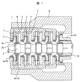
図1は本発明のターボ機械としての一軸多段遠心ポンプの部分縦断面図である。まず、この図1により本実施例1のターボ機械の全体構成を説明する。なお、一軸多段遠心ポンプとしては、例えばボイラ給水ポンプなどがある。 FIG. 1 is a partial longitudinal sectional view of a single-shaft multistage centrifugal pump as a turbomachine of the present invention. First, the overall configuration of the turbo machine according to the first embodiment will be described with reference to FIG. An example of the single-shaft multistage centrifugal pump is a boiler feed pump.
図1において、本実施例のターボ機械1は、羽根車2を有するロータ3、このロータ3を回転自在に支持する軸受(図示せず)、ロータ3を内包して静止流路4を形成する内側のケーシング(インナーケーシング)5、この内側のケーシング5を内包する外側のケーシング(アウターケーシング)6などにより構成されている。前記静止流路4には、前記羽根車2の吐出側に設けられたディフューザベーン7と、次段羽根車2側に設けられたリターンベーン8が備えられている。
In FIG. 1, a
また、前記羽根車2の口金部2a外周面に対向する静止部内面(この例ではケーシング5の内面)には、ウェアリングリング9aが設けられており、このウェアリングリング9aは、羽根車2の口金部2aと前記静止部との間の隙間をシールするラビリンス軸封装置9を構成している。
A
前記羽根車2の背面側には円筒部2bが設けられており、この円筒部2b外周面に対向する静止部内面(ケーシング5の内面)には、ステージブッシュ9bが設けられており、このステージブッシュ9bは、前記羽根車2の円筒部2bと前記静止部との間の隙間をシールするラビリンス軸封装置9を構成している。
A cylindrical portion 2b is provided on the rear side of the
10は前記ロータ3に作用するスラスト力をバランスさせるためのバランスドラムで、このバランスドラム10の外周面に対向する静止部内面(ケーシング5または6の内面)には、バランスドラム軸封装置9cが設けられており、このバランスドラム軸封装置9cは、前記バランスドラム10と前記静止部との間の隙間をシールするラビリンス軸封装置9を構成している。
次に、上記のように構成されているターボ機械の動作を説明する。前記ロータ3が回転することにより、作動流体(この例では水などの液体)は、前記羽根車2に吸い込まれ、この羽根車2により動圧を与えられて前記静止流路4に吐出され、前記ディフューザベーン7及び前記リターンベーン8を備える前記静止流路4で、動圧が静圧に変換される。これにより高圧の作動流体となり、次段の羽根車2に順次流れて圧力が上昇し、最終段の羽根車2から吐出された高圧の作動流体は需要先等に圧送される。
Next, the operation of the turbomachine configured as described above will be described. As the
ターボ機械1の内部を流れる作動流体の一部は、ケーシング5などの静止部とロータ3との間の間隙部、即ち、前述した羽根車2の口金部2a外周面と静止部間の隙間、羽根車2の円筒部2b外周面と静止部間の隙間、及び前記バランスドラム10の外周面と静止部間との間の隙間等から漏えいする。
Part of the working fluid flowing inside the
これらの漏れ流れを低減するために、前述した各間隙部には、それぞれラビリンス軸封装置9が設けられている。即ち、羽根車2入口の口金部2aには前記ウェアリングリング9a、羽根車2背面の円筒部2bには前記ステージブッシュ9b、最終段羽根車2背面のバランスドラム10の部分にはバランスドラム軸封装置9cがそれぞれ設けられている。
In order to reduce these leakage flows, a labyrinth
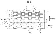
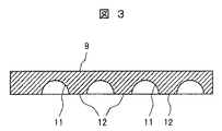
次に、これらの軸封装置の構成を図2、図3を用いて説明する。図2は図1に示すターボ機械における軸封装置の内面形状を説明する図で、軸封装置を円周方向に展開して示す要部展開図、図3は図2のIII−III線矢視断面図である。円周方向を示す矢印は回転方向と一致している。以下同様である。また、漏れ流れは旋回成分を有するため、軸方向から円周方向に傾いて流入する。 Next, the structure of these shaft seal devices will be described with reference to FIGS. 2 is a view for explaining the inner shape of the shaft seal device in the turbo machine shown in FIG. 1, and is a development of a main part showing the shaft seal device in the circumferential direction. FIG. 3 is a sectional view taken along line III-III in FIG. FIG. The arrow indicating the circumferential direction coincides with the rotation direction. The same applies hereinafter. Further, since the leakage flow has a swirling component, it flows in an inclined direction from the axial direction to the circumferential direction.
なお、ターボ機械1に設けられているラビリンス軸封装置9としては、前述したように、羽根車2入口の口金部2aに設けたウェアリングリング9a、羽根車2背面のステージブッシュ9b、及び最終段羽根車2背面部のバランスドラム10に設けたバランスドラム軸封装置9cがある。本実施例では、上記軸封装置9a〜9cにおける内面形状が何れも同一形状となっており、図2、図3に示す軸封装置は、上述したウェアリングリング9a、ステージブッシュ9b、バランスドラム軸封装置9cに共通の構造である。従って、以下の説明では、単に軸封装置(或いはラビリンス軸封装置)9として説明する。
As described above, the labyrinth
図2に示すように、本実施例1における軸封装置9は、その内面に、ロータ3の軸方向に平行な溝、即ち軸方向溝11が多数設けられている。更に詳しく説明すると、軸封装置9の内面には、前記ロータ3の軸方向に平行な同一直線上に、ランド部12を介して断続的に配置された複数(この例では4個)の軸方向溝11で構成された軸方向溝群A(A1,A2,A3,…,A8)が設けられている。この軸方向溝群Aは、軸封装置9内面の円周方向に複数列、隣接配置されている。この周方向に隣接配置された複数列の軸方向溝群は、図2に示す例では、その図示の範囲で、円周方向に8つの軸方向溝群A1,A2,…,A8が設けられている。また、周方向に隣接配置された複数の前記軸方向溝群A1,A2,…,A8は、互いに平行または略平行になるように配置されている。
As shown in FIG. 2, the
また、図2に示す例では、前記軸封装置9を構成する複数の前記軸方向溝11は、前記ロータの円周方向にも軸方向にも、隣り合う溝の位置がずれる千鳥配置となるように設けられている。更に、千鳥配置されている前記複数の軸方向溝11は、それぞれ円周方向の長さよりも軸方向の長さが長くなる長方形状に形成され、前記複数の軸方向溝11が、円周方向には一部が重なるように配置され、軸方向には前記各軸方向溝群A1,A2,…,A8の各軸方向溝11は他の軸方向溝群の軸方向溝11とは重ならないように構成されている。
In the example shown in FIG. 2, the plurality of
前記軸封装置9に設けられている各軸方向溝11は、例えばエンドミルのような円形工具を前記軸封装置9の内面に押しつけることにより、簡単に加工することができ、図3に示すように、半円形(円弧状)の軸方向に平行な溝を、複数個、断続的に形成することが容易に可能である。前記軸方向溝11を断続して形成することにより、作動流体として液体を取り扱う場合に好適なランド部12の長さを十分にとって、ランド部12が厚みを有する軸封装置9を簡単に製作することができる。前記ランド部12の長さを十分にとることにより、軸封装置9からの軸方向の漏れ流量を効果的に低減することが可能となる。
Each
一方、前記軸封装置9の内面には、軸方向に長く円周方向には短い軸方向溝11を、円周方向に多数配置した構成としているので、ロータ3の変位時に軸方向溝11内に流入した作動流体が円周方向に逃げる量を低減でき、これにより前記軸封装置9の振動減衰特性を向上することができる。
On the other hand, on the inner surface of the
また、前記軸封装置9の内面には、複数の前記軸方向溝群A(A1,A2,…,A8)が円周方向に配設されており、各軸方向溝群Aの各軸方向溝11は、円周方向に、千鳥状で且つ一部が重なるように配置されているので、漏れ流れはランド部12と軸方向溝11の部分を交互に通過する。このため、不安定流体力の原因となる旋回方向流れを効果的に抑制できる。
A plurality of axial groove groups A (A1, A2,..., A8) are arranged in the circumferential direction on the inner surface of the
即ち、軸封装置9に流入する漏れ流れが、ロータの回転方向に沿って旋回する旋回流となって軸方向に流れるのを抑制できるため、ロータ3に対して、振動による円周方向のふれまわり運動を更に助長するような不安定流体力が発生するのを低減でき、これによりロータに不安定振動が発生するのを抑制できる。
That is, the leakage flow flowing into the
しかも、本実施例によれば、軸方向への漏れ流れの大部分が、前記ランド部12と前記軸方向溝11の部分を交互に通過することになるが、前記ランド部12は軸方向に十分な厚み(例えば、軸方向溝11の長さの半分以上の長さの厚み)をもっているので、このランド部12を流れる際の粘性摩擦が大となり、また軸方向溝11に流入する際の漏れ流れ流路の急拡大により、軸方向流れも低減することができる。
In addition, according to the present embodiment, most of the leakage flow in the axial direction alternately passes through the
なお、上述した本実施例1における前記軸方向溝11の形状は、円周方向の長さよりも軸方向の長さが長くなる長方形状に形成しているので、軸封装置9に流入した漏れ流れが旋回流となるのを抑制する効果をより大きくできる。但し、前記軸方向溝11の軸方向幅と円周方向幅のアスペクト比は、軸方向に長い長方形状にするものには限定されず、軸方向溝11を形成するための工具の形状に合わせて溝形状を適宜選定しても良く、例えば前記軸方向溝11の軸方向幅と円周方向幅を同程度に構成しても良い。
In addition, since the shape of the
また、上述した軸封装置9は、ターボ機械1の全ての軸封装置9(ウェアリングリング9a、ステージブッシュ9b及びバランスドラム軸封装置9c)に適用することが好ましいが、少なくとも1つの軸封装置9に適用しても良く、特に不安定流体力や漏れ量が大きくなる高圧部の軸封装置9に本発明を適用すれば効果的である。
Further, the
次に、上述した実施例1のターボ機械の変形例を図4〜図13を用いて説明する。各図において、図1〜図3と同一符号を付した部分は同一或いは相当する部分を示しており、ターボ機械1の全体構成は上記実施例1で説明した図1の構成と同様であるので、ターボ機械1の全体構成の説明は省略し、構成が異なる軸封装置9の部分についてのみ説明する。
Next, modified examples of the turbo machine according to the first embodiment will be described with reference to FIGS. In each figure, the parts denoted by the same reference numerals as in FIGS. 1 to 3 indicate the same or corresponding parts, and the overall configuration of the
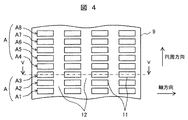
図4、図5により、上述した実施例1における軸封装置9の第1変形例を説明する。図4は図1に示すターボ機械における軸封装置の第1変形例を示す図で、図2に相当する図、図5は図4のV−V線矢視断面図である。
A first modification of the
図2に示す例では、前記軸封装置9を構成する複数の前記軸方向溝11は、前記ロータ3の円周方向にも軸方向にも千鳥配置となるように設けられているが、この第1変形例では、軸方向に平行で長方形状の複数の軸方向溝11を、図4に示すように、隣り合う溝の位置が同一となる格子状に配列したものである。
このように本実施例は、前記軸方向溝11を格子状に配列しても良く、この場合、複数の前記軸方向溝11は、軸方向と円周方向にそれぞれ並んで(同一直線状に)配置されるため、軸方向溝11が存在しない部分であるランド部12が円周方向に連続して形成される。このため、軸封装置9に流入する漏れ流れが、ロータの回転方向に沿って旋回する旋回流となるのを抑制する効果は減少する。しかし、この第1変形例の構成とすることにより、前記軸方向溝11を加工する際の工具や素材の位置決め作業が軽減されるので、製作性を大幅に向上できる効果が得られる。
In the example shown in FIG. 2, the plurality of
As described above, in the present embodiment, the
図6、図7により、上述した実施例1における軸封装置9の第2変形例を説明する。図6は図1に示すターボ機械における軸封装置の第2変形例を示す図で、図2に相当する図、図7は図6のVII−VII線矢視断面図である。
A second modification of the
図2に示す例では、軸方向に長い前記軸方向溝11の軸方向断面形状を半円形の円弧状とした例を示したが、この第2変形例では、図7に示すように、前記軸方向溝11の軸方向断面形状を略矩形状としたものである。このように、前記軸方向溝11の軸方向断面形状は円弧状に限られるものではなく、円弧以外の形状、例えば矩形、楕円、台形、或いは三角形などの形状にすることも可能であり、同様の漏れ流れ低減効果や不安定流体力低減効果が得られる。なお、図3に示すような円弧状にすれば、軸方向溝11の加工を容易に行うことができる利点がある。
In the example shown in FIG. 2, an example in which the axial sectional shape of the
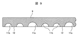
図8、図9により、上述した実施例1における軸封装置9の第3変形例を説明する。図8は図1に示すターボ機械における軸封装置の第3変形例を示す図で、図2に相当する図、図9は図8のIX−IX線矢視断面図である。
A third modification of the
上述した図2〜図7に示した軸封装置9では、全て同じ形状及び寸法の軸方向溝11を設けた例を説明したが、この第3変形例では、図8、図9に示すように、前記軸方向溝11を、軸方向及び径方向の寸法が大きい大溝11aと、軸方向及び径方向の寸法が小さい小溝11bの2種類の溝で構成したものである。前記大溝11aは、前記小溝11bが軸方向に数個設けられる毎に、1個ずつ設けるようにすると良い。この図8、図9に示す例では、前記小溝11bが軸方向に2個設けられる毎に、1個の前記大溝11aが配置されるように構成している。円周方向に複数設けられている各軸方向溝群A1,A2,…,A8についても同様に構成されている。
In the
前記大溝11aは、流れの一様性を阻害することにより、不安定流体力の発生要因である旋回流れの成長をより効果的に抑制できるので、不安定流体力の低減効果を向上できる。なお、前記軸方向溝11の種類は2種類には限られず、軸方向及び径方向の寸法が異なる溝を3種類以上として構成しても良い。
Since the
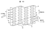
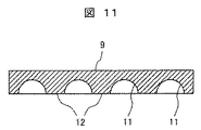
図10、図11により、上述した実施例1における軸封装置9の第4変形例を説明する。図10は図1に示すターボ機械における軸封装置の第4変形例を示す図で、図2に相当する図、図11は図10のXI−XI線矢視断面図である。
A fourth modification of the
上述した図2〜図9に示した軸封装置9では、前記軸方向溝11を軸方向に平行な溝とし、円周方向に複数設けられている各軸方向溝群A1,A2,…,A8についても、それぞれ軸方向に互いに平行となるように配置している例を説明した。これに対して、この第4変形例では、図10に示すように、前記軸方向溝11を、ロータ3の軸方向から回転方向(円周方向)に傾斜させて設け、円周方向に複数設けられている各軸方向溝群A1,A2,…,A8についても、それぞれ軸方向から回転方向に傾斜させて互いに平行となるように配置している。
In the
このように、軸封装置9を構成する軸方向溝11や軸方向溝群A1,A2,…,A8をロータ3の軸方向から回転方向に傾斜させることにより、軸封装置9に流入する漏れ流れの方向に前記軸方向溝11の方向を近づけることができるので、漏れ流れの流速をより効率的に減速することができる。従って、漏れ流れをより低減できると共に、不安定流体力も効果的に抑制することができる。
As described above, the
なお、軸封装置9は漏れ流れをできるだけ抑制する必要があるため、前記軸方向溝11の方向或いは前記軸方向溝群A1,A2,…,A8の方向は、ロータ3の軸方向との為す角を45゜未満、すなわち回転方向とのなす角を45゜以上とすることが好ましい。また、ロータ3の軸方向との為す角が45゜未満の溝や溝群についても、本発明の説明では、それぞれ軸方向溝、軸方向溝群と称する。
Since the
図12、図13により、上述した実施例1における軸封装置9の第5変形例を説明する。図12は図1に示すターボ機械における軸封装置の第5変形例を示す図で、図2に相当する図、図13は図12のXIII−XIII線矢視断面図である。
A fifth modification of the
この第5変形例は、図2、図3に示す実施例1の前記軸封装置9の一部変形例であり、基本構成は図2、図3に示すものと同様であり、異なる点を中心に説明する。
この第5変形例においては、複数の軸方向溝11は、ロータ3の軸方向に千鳥配置となるように配置されている点では図2、図3に示す例と同様である。但し、図2、図3に示す例では、軸方向の同一直線上に配置されている軸方向溝11は、他の同一直線上の軸方向溝11とは重ならないように構成しているが、この第5変形例では、軸方向の同一直線上に配置されている軸方向溝11は、周方向に隣接配置されている他の軸方向溝11、或いは他の同一直線上の軸方向溝11と一部が重なるように構成しているものである。
This fifth modification is a partial modification of the
In the fifth modification, the plurality of
図12で説明すると、例えば、軸方向溝群A1の軸方向溝11は、円周方向に隣接する軸方向溝群A2(図2の例では溝が1つのみ)の軸方向溝11と軸方向に一部が重なるように配置されている。他の軸方向溝群A3〜A12についても同様である。また、円周方向に対しては、前記各軸方向溝群A1〜A12の各軸方向溝11は円周方向に隣接する他の軸方向溝群の軸方向溝11とは重ならないように構成されている。従って、この第5変形例では、ランド部12が周方向に連続して設けられている。他の構成は図2、図3に示す例と同様である。
Referring to FIG. 12, for example, the
この第5変形例によれば、軸方向溝11が軸方向に一部重なる構成としているので、軸方向の漏れ流れをより低減できる効果が得られる。
According to the fifth modification, since the
以上説明したように、本発明の上記実施例や各変形例によれば、軸封装置は、その内周面に、ロータの軸方向及び円周方向にランド部を介して断続的に配置された複数の軸方向溝が設けられているので、作動流体として液体を取り扱うターボ機械の軸封装置における作動流体の漏えいを低減すると共に、ロータに作用する不安定流体力も低減することのできるターボ機械を得ることができる。 As described above, according to the above-described embodiments and modifications of the present invention, the shaft seal device is intermittently disposed on the inner peripheral surface of the rotor in the axial direction and the circumferential direction of the rotor via the land portions. In addition, since a plurality of axial grooves are provided, the turbomachine capable of reducing leakage of the working fluid in the shaft seal device of the turbomachine that handles the liquid as the working fluid and also reducing the unstable fluid force acting on the rotor Can be obtained.
なお、本発明は上記した実施例に限定されるものではなく、様々な変形例が含まれる。例えば、上記実施例では、ターボ機械としての一軸多段遠心ポンプに本発明を適用した場合の例について説明したが、本発明は一軸多段遠心ポンプに限られるものではなく、単段の遠心ポンプや、ポンプ水車及び水車等にも同様に適用可能である。
また、上述した実施例或いは変形例の構成の一部を他の変形例の構成に置き換えることが可能であり、上記実施例或いはある変形例の構成に他の変形例の構成を加えることも可能である。更に、上記した実施例は本発明を分かり易く説明するために詳細に説明したものであり、必ずしも説明した全ての構成を備えるものに限定されるものではない。
In addition, this invention is not limited to an above-described Example, Various modifications are included. For example, in the above embodiment, an example in which the present invention is applied to a single-shaft multistage centrifugal pump as a turbomachine has been described, but the present invention is not limited to a single-shaft multistage centrifugal pump, The same applies to pump turbines and turbines.
Further, a part of the configuration of the above-described embodiment or modification can be replaced with the configuration of another modification, and the configuration of another modification can be added to the configuration of the above-described embodiment or some modification. It is. Further, the above-described embodiments have been described in detail for easy understanding of the present invention, and are not necessarily limited to those having all the configurations described.
1…ターボ機械、2…羽根車、3…ロータ、
4…静止流路、
5,6…ケーシング(5…インナーケーシング、6…アウターケーシング)、
7…ディフューザベーン、8…リターンベーン、
9…軸封装置(ラビリンス軸封装置)
9a…ウェアリングリング、9b…ステージブッシュ、9c…バランスドラム軸封装置、10…バランスドラム、
11…軸方向溝(溝)、11a…大溝、11b…小溝、12…ランド部、
A(A1,A2,…,A12)…軸方向溝群。
1 ... turbomachine, 2 ... impeller, 3 ... rotor,
4 ... static flow path,
5, 6 ... casing (5 ... inner casing, 6 ... outer casing),
7 ... Diffuser vane, 8 ... Return vane,
9. Shaft seal device (labyrinth shaft seal device)
9a ... Wear ring, 9b ... Stage bush, 9c ... Balance drum shaft seal device, 10 ... Balance drum,
11 ... Axial groove (groove), 11a ... large groove, 11b ... small groove, 12 ... land part,
A (A1, A2,..., A12)... Axial groove group.
Claims (12)
前記作動流体は液体であり、
前記軸封装置は、その内周面に、前記ロータの軸方向及び円周方向にランド部を介して断続的に配置された複数の軸方向溝が設けられている
ことを特徴とするターボ機械。 A rotor having an impeller, a bearing that rotatably supports the rotor, a casing that includes the rotor to form a stationary flow path, and leakage of working fluid from a gap between the casing and the rotor is reduced. A turbomachine having a shaft seal device,
The working fluid is a liquid;
The turbomachine characterized in that the shaft sealing device is provided with a plurality of axial grooves that are intermittently arranged via land portions in the axial direction and the circumferential direction of the rotor on an inner peripheral surface thereof. .
前記作動流体は液体であり、
前記軸封装置は、その内周面に、軸方向の同一直線上にランド部を介して断続的に配置された複数の軸方向溝を有する軸方向溝群を備え、
前記軸方向溝群は円周方向に複数隣接配置され、周方向に隣接配置された複数の前記軸方向溝群はランド部を介して互いに平行になるように設けられている
ことを特徴とするターボ機械。 A rotor having an impeller, a bearing that rotatably supports the rotor, a casing that includes the rotor to form a stationary flow path, and leakage of working fluid from a gap between the casing and the rotor is reduced. A turbomachine having a shaft seal device,
The working fluid is a liquid;
The shaft sealing device includes an axial groove group having a plurality of axial grooves intermittently arranged via land portions on the same straight line in the axial direction on the inner peripheral surface thereof.
A plurality of the axial groove groups are arranged adjacent to each other in the circumferential direction, and the plurality of axial groove groups arranged adjacent to each other in the circumferential direction are provided so as to be parallel to each other via a land portion. Turbo machine.
Priority Applications (3)
| Application Number | Priority Date | Filing Date | Title |
|---|---|---|---|
| JP2016046891A JP2017160861A (en) | 2016-03-10 | 2016-03-10 | Turbo machine |
| EP17000320.6A EP3217016B1 (en) | 2016-03-10 | 2017-03-01 | Turbomachine |
| US15/454,865 US10718348B2 (en) | 2016-03-10 | 2017-03-09 | Turbomachine |
Applications Claiming Priority (1)
| Application Number | Priority Date | Filing Date | Title |
|---|---|---|---|
| JP2016046891A JP2017160861A (en) | 2016-03-10 | 2016-03-10 | Turbo machine |
Publications (1)
| Publication Number | Publication Date |
|---|---|
| JP2017160861A true JP2017160861A (en) | 2017-09-14 |
Family
ID=58227882
Family Applications (1)
| Application Number | Title | Priority Date | Filing Date |
|---|---|---|---|
| JP2016046891A Pending JP2017160861A (en) | 2016-03-10 | 2016-03-10 | Turbo machine |
Country Status (3)
| Country | Link |
|---|---|
| US (1) | US10718348B2 (en) |
| EP (1) | EP3217016B1 (en) |
| JP (1) | JP2017160861A (en) |
Families Citing this family (2)
| Publication number | Priority date | Publication date | Assignee | Title |
|---|---|---|---|---|
| CN108730196A (en) * | 2018-08-07 | 2018-11-02 | 安德里茨(中国)有限公司 | Sectional type multi-stage pump |
| US11773738B2 (en) * | 2021-12-09 | 2023-10-03 | Rtx Corporation | Radial lift seal |
Citations (10)
| Publication number | Priority date | Publication date | Assignee | Title |
|---|---|---|---|---|
| JPS53117158A (en) * | 1977-03-23 | 1978-10-13 | Hitachi Ltd | Floating ring seal |
| JPS6116294A (en) * | 1984-07-04 | 1986-01-24 | Hitachi Ltd | Fluid leakage preventing device in fluid machine |
| JPH0271115U (en) * | 1988-11-17 | 1990-05-30 | ||
| JP2010196797A (en) * | 2009-02-25 | 2010-09-09 | Mitsubishi Heavy Ind Ltd | Sealant |
| US20110049809A1 (en) * | 2009-08-27 | 2011-03-03 | Garrison Glenn M | Hydrodynamic Circumferential Seal System for Large Translations |
| JP2011185272A (en) * | 1999-12-20 | 2011-09-22 | Sulzer Metco Ag | Profiled surface used as abradable coating in fluid machine |
| WO2014077058A1 (en) * | 2012-11-13 | 2014-05-22 | 三菱重工コンプレッサ株式会社 | Rotary machine |
| JP2014126139A (en) * | 2012-12-26 | 2014-07-07 | Kawasaki Heavy Ind Ltd | Non-contact annular seal |
| JP2014219023A (en) * | 2013-05-02 | 2014-11-20 | 株式会社荏原製作所 | Non-contact annular seal |
| JP2014238066A (en) * | 2013-06-10 | 2014-12-18 | 三菱重工業株式会社 | Rotary machine |
Family Cites Families (26)
| Publication number | Priority date | Publication date | Assignee | Title |
|---|---|---|---|---|
| US1622911A (en) * | 1924-05-13 | 1927-03-29 | Firm Feodor Burgmann | Packing of rotary shafts |
| US3259393A (en) * | 1964-09-02 | 1966-07-05 | Gen Motors Corp | Lip seal for rotary shaft with patterned grooves |
| US3529905A (en) * | 1966-12-12 | 1970-09-22 | Gen Motors Corp | Cellular metal and seal |
| NL6812699A (en) * | 1968-09-05 | 1970-03-09 | ||
| US3861825A (en) * | 1970-12-21 | 1975-01-21 | Borg Warner | Multistage pump and manufacturing method |
| US4545586A (en) * | 1983-04-28 | 1985-10-08 | The United States Of America As Represented By The Administrator Of The National Aeronautics And Space Administration | Damping seal for turbomachinery |
| JPH0271115A (en) | 1988-05-31 | 1990-03-09 | Ichikoh Ind Ltd | Photoelectric leveling apparatus |
| US4927326A (en) * | 1989-05-26 | 1990-05-22 | The United States Of America As Represented By The Administrator Of The National Aeronautics And Space Administration | Turbomachinery rotor support with damping |
| DE9001229U1 (en) * | 1990-02-03 | 1990-04-12 | Ksb Aktiengesellschaft, 6710 Frankenthal, De | |
| US5190440A (en) * | 1991-03-11 | 1993-03-02 | Dresser-Rand Company | Swirl control labyrinth seal |
| EP0689650A1 (en) * | 1993-01-08 | 1996-01-03 | THE TEXAS A&M UNIVERSITY SYSTEM | Pressure damper seals |
| JP3573590B2 (en) | 1997-03-19 | 2004-10-06 | 株式会社 日立インダストリイズ | Centrifugal pump |
| JP3567064B2 (en) * | 1997-06-23 | 2004-09-15 | 株式会社 日立インダストリイズ | Labyrinth seal device and fluid machine provided with the same |
| US20030047880A1 (en) * | 2001-09-07 | 2003-03-13 | Ross Colby M. | Seal and method |
| WO2004113771A2 (en) * | 2003-06-20 | 2004-12-29 | Elliott Company | Hybrid abradable labyrinth damper seal |
| JP2006214289A (en) * | 2005-02-01 | 2006-08-17 | Hitachi Industries Co Ltd | Industrial pump and manufacturing method thereof |
| US8074998B2 (en) * | 2006-05-05 | 2011-12-13 | The Texas A&M University System | Annular seals for non-contact sealing of fluids in turbomachinery |
| US20080206542A1 (en) * | 2007-02-22 | 2008-08-28 | Siemens Power Generation, Inc. | Ceramic matrix composite abradable via reduction of surface area |
| US7819625B2 (en) * | 2007-05-07 | 2010-10-26 | Siemens Energy, Inc. | Abradable CMC stacked laminate ring segment for a gas turbine |
| US8905408B2 (en) * | 2008-05-22 | 2014-12-09 | Stein Seal Company | Windback device for a circumferential seal |
| US9909440B2 (en) * | 2011-03-24 | 2018-03-06 | Dresser-Rand Company | Interlocking hole pattern seal |
| EP2636931B1 (en) * | 2011-03-30 | 2019-08-07 | Eagle Industry Co., Ltd. | Seal device |
| ITCO20110029A1 (en) * | 2011-07-26 | 2013-01-27 | Nuovo Pignone Spa | CENTRIFUGAL AND TURBOMACHINE IMPELLER |
| JP6049385B2 (en) | 2012-10-04 | 2016-12-21 | 株式会社日立製作所 | Centrifugal compressor |
| CN104813082B (en) * | 2012-12-06 | 2016-12-07 | 三菱重工压缩机有限公司 | Sealing device and rotating machinery |
| BR102016016335A2 (en) * | 2015-10-14 | 2017-04-25 | Sulzer Management Ag | pump to drive a highly viscous fluid |
-
2016
- 2016-03-10 JP JP2016046891A patent/JP2017160861A/en active Pending
-
2017
- 2017-03-01 EP EP17000320.6A patent/EP3217016B1/en active Active
- 2017-03-09 US US15/454,865 patent/US10718348B2/en active Active
Patent Citations (10)
| Publication number | Priority date | Publication date | Assignee | Title |
|---|---|---|---|---|
| JPS53117158A (en) * | 1977-03-23 | 1978-10-13 | Hitachi Ltd | Floating ring seal |
| JPS6116294A (en) * | 1984-07-04 | 1986-01-24 | Hitachi Ltd | Fluid leakage preventing device in fluid machine |
| JPH0271115U (en) * | 1988-11-17 | 1990-05-30 | ||
| JP2011185272A (en) * | 1999-12-20 | 2011-09-22 | Sulzer Metco Ag | Profiled surface used as abradable coating in fluid machine |
| JP2010196797A (en) * | 2009-02-25 | 2010-09-09 | Mitsubishi Heavy Ind Ltd | Sealant |
| US20110049809A1 (en) * | 2009-08-27 | 2011-03-03 | Garrison Glenn M | Hydrodynamic Circumferential Seal System for Large Translations |
| WO2014077058A1 (en) * | 2012-11-13 | 2014-05-22 | 三菱重工コンプレッサ株式会社 | Rotary machine |
| JP2014126139A (en) * | 2012-12-26 | 2014-07-07 | Kawasaki Heavy Ind Ltd | Non-contact annular seal |
| JP2014219023A (en) * | 2013-05-02 | 2014-11-20 | 株式会社荏原製作所 | Non-contact annular seal |
| JP2014238066A (en) * | 2013-06-10 | 2014-12-18 | 三菱重工業株式会社 | Rotary machine |
Also Published As
| Publication number | Publication date |
|---|---|
| EP3217016A1 (en) | 2017-09-13 |
| EP3217016B1 (en) | 2019-05-08 |
| US10718348B2 (en) | 2020-07-21 |
| US20170260991A1 (en) | 2017-09-14 |
Similar Documents
| Publication | Publication Date | Title |
|---|---|---|
| JP5416859B2 (en) | Tilting pad type journal bearing and rotating machine having the same | |
| JP5021365B2 (en) | Packing ring assembly with variable spacing and turbine diaphragm | |
| JP2016089768A (en) | Seal device and turbo machine | |
| JP5972374B2 (en) | Axial fluid machine | |
| US10480339B2 (en) | Sealing assembly | |
| EP2154380B1 (en) | Seal device for rotary fluid machine and rotary fluid machine | |
| US11187097B2 (en) | Rotary machine | |
| WO2017150365A1 (en) | Seal structure and turbomachine | |
| JP2013174192A (en) | Turbo machine | |
| JP2017160861A (en) | Turbo machine | |
| JP6167158B2 (en) | Seal structure and turbomachine | |
| US11136897B2 (en) | Seal device and turbomachine | |
| JP6571257B2 (en) | Sealing device and turbomachine | |
| JP2014238066A (en) | Rotary machine | |
| JP2014152696A (en) | Labyrinth seal device, and turbomachine using the same | |
| JP2018040282A (en) | Axial flow turbine and diaphragm outer ring thereof | |
| WO2016024409A1 (en) | Centrifugal rotary machine | |
| JP2019002361A (en) | Turbomachine | |
| JP2017160860A (en) | Turbo machine | |
| JP2013142435A (en) | Seal device | |
| JP5909081B2 (en) | Turbomachine sealing assembly and method for assembling the same | |
| JP7225076B2 (en) | labyrinth seal | |
| JP2023150867A (en) | Rotary machine | |
| WO2017163911A1 (en) | Rotary machine | |
| JP2019124156A (en) | Turbomachine |
Legal Events
| Date | Code | Title | Description |
|---|---|---|---|
| A621 | Written request for application examination |
Free format text: JAPANESE INTERMEDIATE CODE: A621 Effective date: 20180822 |
|
| A977 | Report on retrieval |
Free format text: JAPANESE INTERMEDIATE CODE: A971007 Effective date: 20190617 |
|
| A131 | Notification of reasons for refusal |
Free format text: JAPANESE INTERMEDIATE CODE: A131 Effective date: 20190625 |
|
| A521 | Request for written amendment filed |
Free format text: JAPANESE INTERMEDIATE CODE: A523 Effective date: 20190809 |
|
| A131 | Notification of reasons for refusal |
Free format text: JAPANESE INTERMEDIATE CODE: A131 Effective date: 20200107 |
|
| A711 | Notification of change in applicant |
Free format text: JAPANESE INTERMEDIATE CODE: A712 Effective date: 20200122 |
|
| A521 | Request for written amendment filed |
Free format text: JAPANESE INTERMEDIATE CODE: A523 Effective date: 20200213 |
|
| A02 | Decision of refusal |
Free format text: JAPANESE INTERMEDIATE CODE: A02 Effective date: 20200630 |