WO2019087890A1 - Tilting pad bearing - Google Patents
Tilting pad bearing Download PDFInfo
- Publication number
- WO2019087890A1 WO2019087890A1 PCT/JP2018/039459 JP2018039459W WO2019087890A1 WO 2019087890 A1 WO2019087890 A1 WO 2019087890A1 JP 2018039459 W JP2018039459 W JP 2018039459W WO 2019087890 A1 WO2019087890 A1 WO 2019087890A1
- Authority
- WO
- WIPO (PCT)
- Prior art keywords
- pad
- recess
- liner
- axis
- bearing
- Prior art date
Links
Images


Classifications
-
- F—MECHANICAL ENGINEERING; LIGHTING; HEATING; WEAPONS; BLASTING
- F16—ENGINEERING ELEMENTS AND UNITS; GENERAL MEASURES FOR PRODUCING AND MAINTAINING EFFECTIVE FUNCTIONING OF MACHINES OR INSTALLATIONS; THERMAL INSULATION IN GENERAL
- F16C—SHAFTS; FLEXIBLE SHAFTS; ELEMENTS OR CRANKSHAFT MECHANISMS; ROTARY BODIES OTHER THAN GEARING ELEMENTS; BEARINGS
- F16C17/00—Sliding-contact bearings for exclusively rotary movement
- F16C17/04—Sliding-contact bearings for exclusively rotary movement for axial load only
- F16C17/06—Sliding-contact bearings for exclusively rotary movement for axial load only with tiltably-supported segments, e.g. Michell bearings
-
- F—MECHANICAL ENGINEERING; LIGHTING; HEATING; WEAPONS; BLASTING
- F16—ENGINEERING ELEMENTS AND UNITS; GENERAL MEASURES FOR PRODUCING AND MAINTAINING EFFECTIVE FUNCTIONING OF MACHINES OR INSTALLATIONS; THERMAL INSULATION IN GENERAL
- F16C—SHAFTS; FLEXIBLE SHAFTS; ELEMENTS OR CRANKSHAFT MECHANISMS; ROTARY BODIES OTHER THAN GEARING ELEMENTS; BEARINGS
- F16C17/00—Sliding-contact bearings for exclusively rotary movement
- F16C17/02—Sliding-contact bearings for exclusively rotary movement for radial load only
- F16C17/03—Sliding-contact bearings for exclusively rotary movement for radial load only with tiltably-supported segments, e.g. Michell bearings
-
- F—MECHANICAL ENGINEERING; LIGHTING; HEATING; WEAPONS; BLASTING
- F16—ENGINEERING ELEMENTS AND UNITS; GENERAL MEASURES FOR PRODUCING AND MAINTAINING EFFECTIVE FUNCTIONING OF MACHINES OR INSTALLATIONS; THERMAL INSULATION IN GENERAL
- F16C—SHAFTS; FLEXIBLE SHAFTS; ELEMENTS OR CRANKSHAFT MECHANISMS; ROTARY BODIES OTHER THAN GEARING ELEMENTS; BEARINGS
- F16C17/00—Sliding-contact bearings for exclusively rotary movement
- F16C17/10—Sliding-contact bearings for exclusively rotary movement for both radial and axial load
-
- F—MECHANICAL ENGINEERING; LIGHTING; HEATING; WEAPONS; BLASTING
- F16—ENGINEERING ELEMENTS AND UNITS; GENERAL MEASURES FOR PRODUCING AND MAINTAINING EFFECTIVE FUNCTIONING OF MACHINES OR INSTALLATIONS; THERMAL INSULATION IN GENERAL
- F16C—SHAFTS; FLEXIBLE SHAFTS; ELEMENTS OR CRANKSHAFT MECHANISMS; ROTARY BODIES OTHER THAN GEARING ELEMENTS; BEARINGS
- F16C17/00—Sliding-contact bearings for exclusively rotary movement
- F16C17/12—Sliding-contact bearings for exclusively rotary movement characterised by features not related to the direction of the load
- F16C17/24—Sliding-contact bearings for exclusively rotary movement characterised by features not related to the direction of the load with devices affected by abnormal or undesired positions, e.g. for preventing overheating, for safety
- F16C17/243—Sliding-contact bearings for exclusively rotary movement characterised by features not related to the direction of the load with devices affected by abnormal or undesired positions, e.g. for preventing overheating, for safety related to temperature and heat, e.g. for preventing overheating
-
- F—MECHANICAL ENGINEERING; LIGHTING; HEATING; WEAPONS; BLASTING
- F16—ENGINEERING ELEMENTS AND UNITS; GENERAL MEASURES FOR PRODUCING AND MAINTAINING EFFECTIVE FUNCTIONING OF MACHINES OR INSTALLATIONS; THERMAL INSULATION IN GENERAL
- F16C—SHAFTS; FLEXIBLE SHAFTS; ELEMENTS OR CRANKSHAFT MECHANISMS; ROTARY BODIES OTHER THAN GEARING ELEMENTS; BEARINGS
- F16C27/00—Elastic or yielding bearings or bearing supports, for exclusively rotary movement
- F16C27/02—Sliding-contact bearings
-
- F—MECHANICAL ENGINEERING; LIGHTING; HEATING; WEAPONS; BLASTING
- F16—ENGINEERING ELEMENTS AND UNITS; GENERAL MEASURES FOR PRODUCING AND MAINTAINING EFFECTIVE FUNCTIONING OF MACHINES OR INSTALLATIONS; THERMAL INSULATION IN GENERAL
- F16C—SHAFTS; FLEXIBLE SHAFTS; ELEMENTS OR CRANKSHAFT MECHANISMS; ROTARY BODIES OTHER THAN GEARING ELEMENTS; BEARINGS
- F16C33/00—Parts of bearings; Special methods for making bearings or parts thereof
- F16C33/02—Parts of sliding-contact bearings
- F16C33/04—Brasses; Bushes; Linings
- F16C33/06—Sliding surface mainly made of metal
- F16C33/10—Construction relative to lubrication
- F16C33/1025—Construction relative to lubrication with liquid, e.g. oil, as lubricant
- F16C33/106—Details of distribution or circulation inside the bearings, e.g. details of the bearing surfaces to affect flow or pressure of the liquid
- F16C33/1075—Wedges, e.g. ramps or lobes, for generating pressure
-
- F—MECHANICAL ENGINEERING; LIGHTING; HEATING; WEAPONS; BLASTING
- F16—ENGINEERING ELEMENTS AND UNITS; GENERAL MEASURES FOR PRODUCING AND MAINTAINING EFFECTIVE FUNCTIONING OF MACHINES OR INSTALLATIONS; THERMAL INSULATION IN GENERAL
- F16C—SHAFTS; FLEXIBLE SHAFTS; ELEMENTS OR CRANKSHAFT MECHANISMS; ROTARY BODIES OTHER THAN GEARING ELEMENTS; BEARINGS
- F16C33/00—Parts of bearings; Special methods for making bearings or parts thereof
- F16C33/02—Parts of sliding-contact bearings
- F16C33/04—Brasses; Bushes; Linings
- F16C33/06—Sliding surface mainly made of metal
- F16C33/10—Construction relative to lubrication
- F16C33/1025—Construction relative to lubrication with liquid, e.g. oil, as lubricant
- F16C33/106—Details of distribution or circulation inside the bearings, e.g. details of the bearing surfaces to affect flow or pressure of the liquid
- F16C33/108—Details of distribution or circulation inside the bearings, e.g. details of the bearing surfaces to affect flow or pressure of the liquid with a plurality of elements forming the bearing surfaces, e.g. bearing pads
-
- F—MECHANICAL ENGINEERING; LIGHTING; HEATING; WEAPONS; BLASTING
- F16—ENGINEERING ELEMENTS AND UNITS; GENERAL MEASURES FOR PRODUCING AND MAINTAINING EFFECTIVE FUNCTIONING OF MACHINES OR INSTALLATIONS; THERMAL INSULATION IN GENERAL
- F16C—SHAFTS; FLEXIBLE SHAFTS; ELEMENTS OR CRANKSHAFT MECHANISMS; ROTARY BODIES OTHER THAN GEARING ELEMENTS; BEARINGS
- F16C2360/00—Engines or pumps
- F16C2360/23—Gas turbine engines
-
- F—MECHANICAL ENGINEERING; LIGHTING; HEATING; WEAPONS; BLASTING
- F16—ENGINEERING ELEMENTS AND UNITS; GENERAL MEASURES FOR PRODUCING AND MAINTAINING EFFECTIVE FUNCTIONING OF MACHINES OR INSTALLATIONS; THERMAL INSULATION IN GENERAL
- F16C—SHAFTS; FLEXIBLE SHAFTS; ELEMENTS OR CRANKSHAFT MECHANISMS; ROTARY BODIES OTHER THAN GEARING ELEMENTS; BEARINGS
- F16C33/00—Parts of bearings; Special methods for making bearings or parts thereof
- F16C33/02—Parts of sliding-contact bearings
- F16C33/04—Brasses; Bushes; Linings
- F16C33/06—Sliding surface mainly made of metal
- F16C33/12—Structural composition; Use of special materials or surface treatments, e.g. for rust-proofing
- F16C33/121—Use of special materials
Definitions
- the present invention relates to a tilting pad bearing.
- Priority is claimed on Japanese Patent Application No. 2017-211141, filed Oct. 31, 2017, the content of which is incorporated herein by reference.
- Patent Document 1 describes a journal bearing.
- the journal bearing described in Patent Document 1 supports the rotation shaft by a plurality of pads arranged in the circumferential direction of the rotation shaft. An oil film of lubricating oil is formed between the pad and the outer peripheral surface of the rotating shaft.
- there is one called a tilting pad bearing In the tilting pad bearing, each pad is pivotally supported by a pointed pivot provided on the inner circumferential surface of the housing.
- the present invention has been made in view of the above circumstances, and provides a tilting pad bearing capable of stably supporting a rotating shaft while suppressing an increase in pad temperature and occurrence of local plastic flow. .
- the tilting pad bearing supports the pad disposed so as to face the outer peripheral surface of the rotating shaft, and supports the pad radially outward around the axis of the rotating shaft.
- the liner includes: a liner; and a pivot that supports the pad at a radially outer side about the axis and at a central position in an axial direction of the rotation axis, whereby the pad can swing.
- the surface of the liner facing the pad is at least at the central position, in the direction away from the pad, in one of the surface of the pad facing the pad and the surface of the pad facing the liner. It has a concave recess.
- a recess is formed at the center of either the surface of the liner facing the pad or the surface of the pad facing the liner, and a gap is formed between the liner and the pad.
- Be done That is, when a recess is formed in the liner, when a bearing load acts on the pad, a portion of the pad adjacent to the recess is bent and enters the gap to reduce the contact pressure at the radially inner position of the corresponding portion. Can.
- the central position of the pad in which the recess is formed is bent and the gap is reduced, so the contact pressure at the radially inner position of the corresponding portion Can be reduced.
- the distribution of the contact pressure between the pad and the rotation axis can be prevented from being concentrated only near the position supported by the pivot, and the distribution of the contact pressure can be averaged. Therefore, it can suppress that pad temperature rise and local plastic flow occur.
- the recess according to the first aspect may be formed in an arc shape when viewed from the direction orthogonal to the axis. With this configuration, no corner is formed in the recess. Therefore, under high bearing load conditions, local angular contact can be avoided when the pad is bent and contact between the pad and the inner surface of the recess or contact between the liner and the inner surface of the recess occurs.
- the recess according to the second aspect includes a small recess at a central position in the axial direction, and the small recess is the recess when viewed from a direction orthogonal to the axis. It may be formed in an arc shape having a smaller radius of curvature. By configuring in this manner, a small recess is formed in the recess. Therefore, when the bearing load is large, the central position of the pad can be bent in two steps toward the small recess. This can further suppress the distribution of the contact pressure between the pad and the rotation axis from being concentrated only in the vicinity of the pivot. Therefore, the thickness of the oil film on the pad can be kept more constant.
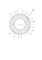
- the tilting pad bearing 100 of this embodiment is used to support the load of the rotating shaft 90 rotating about the axis A from the radial direction around the axis A.
- the tilting pad bearing 100 has an annular housing 1 centered on the axis A, and a plurality of (for example, four) pads 2 circumferentially spaced along the outer peripheral surface of the rotating shaft 90;
- a liner 3 supports the pads 2 from the outside in the radial direction, and a plurality of (for example, four) pivots 4 support the liners 3 on the inner peripheral surface of the housing 1.
- the rotating shaft 90 is used, for example, as a rotor of a rotating machine such as a steam turbine or a gas turbine.
- the rotation axis 90 has a cylindrical shape centered on the axis A. The rotation axis 90 rotates around the axis A.
- the pad 2 has a plate shape curved along the outer peripheral surface of the rotation shaft 90.
- the pad 2 is integrally formed of a metal material such as white metal.
- four pads 2 are arranged at intervals in the circumferential direction of the axis A.
- Lubricating oil is supplied between the inner peripheral surface of the pad 2 and the outer peripheral surface of the rotary shaft 90 by an oil supply device (not shown). The lubricating oil forms an oil film between the pad 2 and the rotating shaft 90.
- Each pad 2 is supported by the liner 3 from the radially outer side.
- the liner 3 when viewed in the direction of the axis A, the liner 3 is in the form of a curved plate having a radius of curvature substantially the same as that of the pad 2.
- the liner 3 is supported by a pivot 4 provided on the inner peripheral surface of the housing 1.
- a radially inner end of the pivot 4 is formed, for example, in a pointed shape, and supports the liner 3 at a point.
- the liner 3 can swing around the tip of the pivot 4.
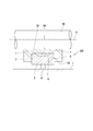
- FIG. 2 is a cross-sectional view of the rotation shaft 90 and the tilting pad bearing 100 in a plane including the axis A.
- the liner 3 is accommodated in an accommodation recess 5 formed in an outer side surface 2 ⁇ / b> A facing radially outward with respect to the axis A among the surfaces of the pad 2.
- the accommodation recess 5 is recessed in the shape of a square groove radially inward with respect to the axis A on the outer side surface 2A.
- the bottom surface 5A of the housing recess 5 is in the form of a plane extending substantially parallel to the axis A.
- the dimension of the liner 3 in the direction of the axis A is smaller than the dimension of the pad 2 in the direction of the axis A, and slightly smaller than the dimension of the accommodation recess 5 in the direction of the axis A.
- the pivot 4 supports the liner 3 from the radially outer side at a central position in the direction of the axis A of the liner 3.
- the inner surface 3A of the liner 3 (that is, the surface facing the pad 2) is formed with a recess 6 recessed in a direction away from the pad 2 (in other words, radially outward around the axis A).
- the recess 6 has an arc-shaped inner surface having a predetermined radius of curvature when viewed in a cross section including the axis A shown in FIG. 2, that is, in a direction orthogonal to the axis A.
- the recess 6 exemplified in this embodiment is formed in a shallow circular groove shape having the same radius of curvature at all positions in the direction orthogonal to the axis A (the front and back direction in FIG. 2).
- the end faces on both sides in the direction of the axis A of the recess 6 in the liner 3 formed in this way are contact portions 7 that contact the outer surface 2 A of the pad 2 (the bottom 5 A of the accommodation recess 5).
- the predetermined radius of curvature of the recess 6 in the liner 3 may be determined by simulation based on, for example, the material of the liner 3, the shape of the liner 3, the shape of the pad 2, the maximum value of the bearing load applied to the pad 2, etc. it can.
- the dimension of the recess 6 in the direction of the axis A is 1/2 or more, and may be 2/3 or more, with respect to the dimension of the liner 3 in the direction of the axis A.
- the recess 6 is formed at the center position of the liner 3 facing the pad 2. Therefore, a gap is formed between the liner 3 and the pad 2. That is, the liner 3 supports the bearing load applied to the pad 2 by the portion excluding the recess 6 (gap). In other words, both sides of the liner 3 adjacent to the recess 6 are pushed by the pad 2. When the bearing load is large, the pad 2 slightly bends in the direction in which the gap of the recess 6 narrows in the radial direction around the axis A.
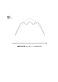
- FIG. 3 is a graph showing the distribution of the contact pressure in the direction of the axis A of the pad 2.
- the solid line indicates the pressure distribution when the recess 6 is formed in the liner 3 as in this embodiment
- the broken line indicates the pressure distribution when the recess 6 is not formed in the liner 3. .
- the pressure distribution of the pad 2 becomes chevron (in other words, reverse V-shaped) when the bearing load increases, and the center supported by the pivot 4 A peak of contact pressure appears at the position.
- the peak value of the pressure distribution is higher than when the recess 6 shown by the broken line is not formed even if the bearing load increases.
- the number of peaks increases from one to three. That is, the pressure distribution is averaged without the contact pressure being concentrated at a local position such as a central position. As a result, it is possible to suppress that the pad temperature rise and the local plastic flow occur.
- a second embodiment of the present invention will be described based on the drawings.
- the second embodiment is different from the first embodiment only in the configuration of the liner 3. Therefore, while attaching and explaining the same code to the same portion as a first embodiment, the overlapping explanation is omitted.
- a recess 6 is formed in the liner 3 of the tilting pad bearing 200 of the second embodiment.
- the small recess 8 is formed in the recess 6.
- the small recess 8 is formed in the recess 6 at a central position in the direction of the axis A.
- the small recess 8 has a smaller radius of curvature than the recess 6.
- the small recessed portion 8 is formed in a shallow circular groove shape having the same radius of curvature at all positions in the direction orthogonal to the axis line A (the front and back direction in FIG. 4). ing.
- the radius of curvature of the small recess 8 may be set in accordance with the peak value of the pressure distribution appearing at the central portion when only the recess 6 is formed.
- the radius of curvature of the small recess 8 can also be determined, for example, by simulation based on various conditions such as the shape and material of the pad 2 and the liner 3 as in the recess 6.
- the small recess 8 is further formed in the recess 6, when the bearing load is large, the pad 2 in the radial direction centering on the axis A, that is, the receiving recess
- the gap between the bottom surface 5A of 5 and the inner surface of the recess 6 can be bent in the narrowing direction.
- the small recessed part 8 is formed, even if the inner surface of the recessed part 6 contacts the pad 2, the condition where the inner surface of the small recessed part 8 does not contact the pad 2 can be created.
- the peak of the load at the central position where the pivot 4 is disposed can be reduced by the portion where the small concave portion 8 is formed and even when the bearing load is large. Thereby, the distribution of the contact pressure between the pad 2 and the rotation shaft 90 can be further suppressed from being concentrated only in the vicinity of the pivot 4.
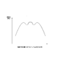
- FIG. 5 is a graph showing the distribution of the contact pressure in the direction of the axis A of the pad 2.
- the solid line shows the pressure distribution in the case where the recess 6 and the small recess 8 are formed in the liner 3 as in this embodiment, and the broken line shows that only the recess 6 is formed in the liner 3 and the small recess 8 is formed. It shows the pressure distribution when not being used.
- the peak value of the pressure distribution is smaller than in the case shown by the broken line, and the number of peaks is three to five. To increase. That is, the pressure distribution is averaged without the contact pressure being concentrated at a local position such as a central position. As a result, it is possible to further suppress the occurrence of the pad temperature rise and the local plastic flow.
- journal bearing in a third embodiment of the present invention will be described based on the drawings.
- the journal bearing of the third embodiment differs from the first embodiment described above only in that a recess is formed on the pad side. Therefore, while attaching and explaining the same code to the same portion as a first embodiment, the overlapping explanation is omitted.
- FIG. 6 is a cross-sectional view corresponding to FIG. 2 in the third embodiment of the present invention.
- the tilting pad bearing 300 in the third embodiment includes a housing 1, a pad 2, a liner 3 and a pivot 4.
- the liner 3 is housed in a housing recess 5 formed on the outer side surface 2A of the pad 2 facing radially outward with respect to the axis A.
- the accommodation recess 5 is recessed in the shape of a square groove radially inward with respect to the axis A on the outer side surface 2A.
- the inner surface 3A of the liner 3 (that is, the surface facing the pad 2) has a planar shape that extends substantially parallel to the axis A in a cross-sectional view in a plane including the axis A.
- the dimension of the liner 3 in the direction of the axis A is smaller than the dimension of the pad 2 in the direction of the axis A, and slightly smaller than the dimension of the accommodation recess 5 in the direction of the axis A.
- the pivot 4 supports the liner 3 from the radially outer side at a central position in the direction of the axis A of the liner 3.
- the bottom surface 5A of the housing recess 5 (that is, the surface facing the inner surface 3A of the liner 3) has a recess 306 recessed in a direction away from the liner 3 (in other words, radially inward around the axis A). It is formed. Similar to the recess 6 of the first embodiment described above, the recess 306 has an arc-shaped inner surface having a predetermined radius of curvature when viewed in a cross section including the axis A shown in FIG. 6, ie, a direction orthogonal to the axis A. have.
- the concave portion 306 exemplified in this embodiment is formed in a shallow circular groove shape having the same radius of curvature at all positions in the direction orthogonal to the axis A (the front and back direction in the drawing of FIG. 6).
- the end surface (bottom surface 5A of the accommodation recess 5) on both sides in the axial line A direction of the recess 306 in the pad 2 thus formed is an abutment portion 307 that abuts on the inner side surface 3A of the liner 3.
- the predetermined curvature radius of the concave portion 306 in the pad 2 is, for example, the material of the pad 2, the shape of the liner 3, the shape of the pad 2, the maximum value of the bearing load applied to the pad 2, etc. Based on this, it can be obtained by simulation or the like.
- the dimension of the recess 306 in the direction of the axis A is 1/2 or more, and may be 2/3 or more, with respect to the dimension of the liner 3 in the direction of the axis A.
- the recess 306 is formed at the central position of the pad 2 facing the liner 3. Therefore, a gap is formed between the liner 3 and the pad 2. That is, the liner 3 supports the bearing load applied to the pad 2 by the portion excluding the recess 306 (gap). In other words, both sides of the liner 3 adjacent to the recess 306 are pushed by the pad 2. When the bearing load is large, the pad 2 slightly bends in the direction in which the gap of the recess 306 narrows in the radial direction around the axis A.
- the present invention is not limited to the configurations of the above-described embodiments, and design changes can be made without departing from the scope of the invention.
- the configuration in which four pads 2 are provided has been described.
- the number of pads 2 is not limited to four, and may be four or less or five or more.
- Reference Signs List 1 housing 2 pad 2A outer surface 3 liner 3A inner surface 4 pivot 5 accommodation recess 5A bottom surface 6, 306 recess 306A inner surface 7 contact portion 8, 308 small recess 90 rotation shaft 100, 200, 300 tilting pad bearing A axis
Abstract
A tilting pad bearing (100) comprises: a pad (2) disposed opposite the outer peripheral surface of a rotating shaft (90); a liner (3) for supporting the pad (2) outward in a radial direction about the axis (A) of the rotating shaft (90); and a pivot (4) that makes the pad (2) swingable by supporting the liner (3) outward in the radial direction about the axis (A) and at the central position of the rotating shaft (90) in the axis (A) direction. The surface of the liner (3) opposite the pad (2) or the surface of the pad (2) opposite the liner (3) has, at least at the central position, a recessed section (6) recessed in a direction away from the pad (2).
Description
この発明は、ティルティングパッド軸受に関する。
本願は、2017年10月31日に、日本に出願された特願2017-211141号に基づき優先権を主張し、その内容をここに援用する。 The present invention relates to a tilting pad bearing.
Priority is claimed on Japanese Patent Application No. 2017-211141, filed Oct. 31, 2017, the content of which is incorporated herein by reference.
本願は、2017年10月31日に、日本に出願された特願2017-211141号に基づき優先権を主張し、その内容をここに援用する。 The present invention relates to a tilting pad bearing.
Priority is claimed on Japanese Patent Application No. 2017-211141, filed Oct. 31, 2017, the content of which is incorporated herein by reference.
蒸気タービンやガスタービン等の回転機械では、回転軸の軸端を軸受によって支持することが一般的である。軸受は、荷重を支持する方向の違いによって、スラスト軸受とジャーナル軸受とに分けられる。スラスト軸受は、回転軸の軸線方向における荷重を支持する。ジャーナル軸受は、軸線の径方向における荷重を支持する。
特許文献1には、ジャーナル軸受が記載されている。この特許文献1に記載されたジャーナル軸受は、回転軸の周方向に配列された複数のパッドによって回転軸を支持する。そして、パッドと回転軸の外周面との間には潤滑油による油膜が形成されている。
ここで、パッド型軸受の中には、ティルティングパッド軸受と呼ばれるものがある。ティルティングパッド軸受では、ハウジングの内周面に設けられた尖頭状のピボットによって各パッドが揺動可能に支持される。 In rotary machines such as steam turbines and gas turbines, it is common to support the shaft end of the rotary shaft with a bearing. Bearings are divided into thrust bearings and journal bearings depending on the direction of load support. The thrust bearing supports the load in the axial direction of the rotating shaft. The journal bearings support the load in the radial direction of the axis.
Patent Document 1 describes a journal bearing. The journal bearing described in Patent Document 1 supports the rotation shaft by a plurality of pads arranged in the circumferential direction of the rotation shaft. An oil film of lubricating oil is formed between the pad and the outer peripheral surface of the rotating shaft.
Here, among the pad-type bearings, there is one called a tilting pad bearing. In the tilting pad bearing, each pad is pivotally supported by a pointed pivot provided on the inner circumferential surface of the housing.
特許文献1には、ジャーナル軸受が記載されている。この特許文献1に記載されたジャーナル軸受は、回転軸の周方向に配列された複数のパッドによって回転軸を支持する。そして、パッドと回転軸の外周面との間には潤滑油による油膜が形成されている。
ここで、パッド型軸受の中には、ティルティングパッド軸受と呼ばれるものがある。ティルティングパッド軸受では、ハウジングの内周面に設けられた尖頭状のピボットによって各パッドが揺動可能に支持される。 In rotary machines such as steam turbines and gas turbines, it is common to support the shaft end of the rotary shaft with a bearing. Bearings are divided into thrust bearings and journal bearings depending on the direction of load support. The thrust bearing supports the load in the axial direction of the rotating shaft. The journal bearings support the load in the radial direction of the axis.
Here, among the pad-type bearings, there is one called a tilting pad bearing. In the tilting pad bearing, each pad is pivotally supported by a pointed pivot provided on the inner circumferential surface of the housing.
しかしながら、特許文献1に記載されているようなジャーナル軸受において、軸受荷重が大きくなった場合、パッド表面とロータ表面との接触が生じる低速回転域では、ロータとパッドとの接触圧力の大部分がピボット付近に集中し、パッドのピボット付近に局所的な塑性流動等を生じる可能性がある。
However, in the journal bearing as described in Patent Document 1, when the bearing load increases, most of the contact pressure between the rotor and the pad is low in the low speed rotation region where contact between the pad surface and the rotor surface occurs. It is concentrated near the pivot, and local plastic flow etc. may occur near the pivot of the pad.
この発明は、上記事情に鑑みてなされたものであり、パッド温度上昇及び局所的な塑性流動が生じることを抑制し、安定的に回転軸を支持することが可能なティルティングパッド軸受を提供する。
The present invention has been made in view of the above circumstances, and provides a tilting pad bearing capable of stably supporting a rotating shaft while suppressing an increase in pad temperature and occurrence of local plastic flow. .
上記の課題を解決するために以下の構成を採用する。
この発明の第一の態様によれば、ティルティングパッド軸受は、回転軸の外周面に対向して配置されたパッドと、前記パッドを前記回転軸の軸線を中心とした径方向外側で支持するライナと、前記ライナを、前記軸線を中心とした径方向外側、かつ、前記回転軸の軸線方向の中央位置で支持することで、前記パッドを揺動可能とするピボットと、を備え、前記ライナの前記パッドに対向する面と、前記パッドの前記ライナに対向する面と、の何れか一方には、前記ライナの前記パッドに対向する面は、少なくとも前記中央位置に、前記パッドから離れる方向に凹む凹部を備える。
このように構成することで、パッドと対向するライナの面と、ライナと対向するパッドの面と、の何れか一方の中央位置に凹部が形成され、ライナとパッドとの間には隙間が形成される。即ち、凹部がライナに形成される場合、パッドに軸受荷重が作用すると、パッドのうち、凹部に隣接する部分は撓んで隙間内に入り込み、該当部位の径方向内側位置における接触圧力を低減することができる。同様に、凹部がパッドに形成される場合、パッドに軸受荷重が作用すると、凹部の形成されているパッドの中央位置が撓んで、隙間が減少するので、該当部位の径方向内側位置における接触圧力を低減することができる。これにより、パッドと回転軸との接触圧力の分布が、ピボットに支持される位置の近くのみに集中することを抑制し、接触圧力の分布を平均化することができる。したがって、パッド温度上昇及び局所的な塑性流動が生じることを抑制することができる。 In order to solve the above problems, the following configuration is adopted.
According to the first aspect of the present invention, the tilting pad bearing supports the pad disposed so as to face the outer peripheral surface of the rotating shaft, and supports the pad radially outward around the axis of the rotating shaft. The liner includes: a liner; and a pivot that supports the pad at a radially outer side about the axis and at a central position in an axial direction of the rotation axis, whereby the pad can swing. The surface of the liner facing the pad is at least at the central position, in the direction away from the pad, in one of the surface of the pad facing the pad and the surface of the pad facing the liner. It has a concave recess.
With this configuration, a recess is formed at the center of either the surface of the liner facing the pad or the surface of the pad facing the liner, and a gap is formed between the liner and the pad. Be done. That is, when a recess is formed in the liner, when a bearing load acts on the pad, a portion of the pad adjacent to the recess is bent and enters the gap to reduce the contact pressure at the radially inner position of the corresponding portion. Can. Similarly, when a recess is formed in the pad, when the bearing load acts on the pad, the central position of the pad in which the recess is formed is bent and the gap is reduced, so the contact pressure at the radially inner position of the corresponding portion Can be reduced. Thereby, the distribution of the contact pressure between the pad and the rotation axis can be prevented from being concentrated only near the position supported by the pivot, and the distribution of the contact pressure can be averaged. Therefore, it can suppress that pad temperature rise and local plastic flow occur.
この発明の第二の態様によれば、第一の態様に係る前記凹部は、前記軸線に直交する方向から見て、円弧状に形成されていてもよい。
このように構成することで、凹部内に角部が形成されていない。そのため、軸受荷重が高い条件下で、パッドが撓んでパッドと凹部の内面との接触、又はライナと凹部の内面との接触が生じた際に、局所的な角当たりを回避することができる。 According to the second aspect of the present invention, the recess according to the first aspect may be formed in an arc shape when viewed from the direction orthogonal to the axis.
With this configuration, no corner is formed in the recess. Therefore, under high bearing load conditions, local angular contact can be avoided when the pad is bent and contact between the pad and the inner surface of the recess or contact between the liner and the inner surface of the recess occurs.
この発明の第三の態様によれば、第二の態様に係る前記凹部は、前記軸線方向の中央位置に小凹部を備え、前記小凹部は、前記軸線に直交する方向から見て、前記凹部よりも小さな曲率半径を有する円弧状に形成されていてもよい。
このように構成することで、凹部内に小凹部が形成される。そのため、軸受荷重が大きい場合には、パッドの中央位置が、小凹部に向けて二段階に撓むことができる。これにより、パッドと回転軸との接触圧力の分布が、ピボットの付近のみに集中することをさらに抑制できる。したがって、パッド上における油膜の厚さをさらに一定に保つことができる。 According to a third aspect of the present invention, the recess according to the second aspect includes a small recess at a central position in the axial direction, and the small recess is the recess when viewed from a direction orthogonal to the axis. It may be formed in an arc shape having a smaller radius of curvature.
By configuring in this manner, a small recess is formed in the recess. Therefore, when the bearing load is large, the central position of the pad can be bent in two steps toward the small recess. This can further suppress the distribution of the contact pressure between the pad and the rotation axis from being concentrated only in the vicinity of the pivot. Therefore, the thickness of the oil film on the pad can be kept more constant.
上記ティルティングパッド軸受によれば、パッド温度上昇及び局所的な塑性流動が生じることを抑制し、安定的に回転軸を支持することが可能となる。
According to the above-mentioned tilting pad bearing, it is possible to suppress the rise of the pad temperature and the occurrence of the local plastic flow and stably support the rotating shaft.
(第一実施形態)
次に、この発明の第一実施形態におけるジャーナル軸受を図面に基づき説明する。
図1、図2に示すように、この実施形態のティルティングパッド軸受100は、軸線A回りに回転する回転軸90の荷重を、軸線Aを中心とした径方向から支持するために用いられる。ティルティングパッド軸受100は、軸線Aを中心とする円環状のハウジング1と、回転軸90の外周面に沿って周方向に間隔をあけて配置された複数(例えば4つ)のパッド2と、各パッド2を径方向外側から支持するライナ3と、各ライナ3をハウジング1の内周面上で支持する複数(例えば4つ)のピボット4と、を備えている。 First Embodiment
Next, a journal bearing in a first embodiment of the present invention will be described based on the drawings.
As shown in FIG. 1 and FIG. 2, the tilting pad bearing 100 of this embodiment is used to support the load of the rotatingshaft 90 rotating about the axis A from the radial direction around the axis A. The tilting pad bearing 100 has an annular housing 1 centered on the axis A, and a plurality of (for example, four) pads 2 circumferentially spaced along the outer peripheral surface of the rotating shaft 90; A liner 3 supports the pads 2 from the outside in the radial direction, and a plurality of (for example, four) pivots 4 support the liners 3 on the inner peripheral surface of the housing 1.
次に、この発明の第一実施形態におけるジャーナル軸受を図面に基づき説明する。
図1、図2に示すように、この実施形態のティルティングパッド軸受100は、軸線A回りに回転する回転軸90の荷重を、軸線Aを中心とした径方向から支持するために用いられる。ティルティングパッド軸受100は、軸線Aを中心とする円環状のハウジング1と、回転軸90の外周面に沿って周方向に間隔をあけて配置された複数(例えば4つ)のパッド2と、各パッド2を径方向外側から支持するライナ3と、各ライナ3をハウジング1の内周面上で支持する複数(例えば4つ)のピボット4と、を備えている。 First Embodiment
Next, a journal bearing in a first embodiment of the present invention will be described based on the drawings.
As shown in FIG. 1 and FIG. 2, the tilting pad bearing 100 of this embodiment is used to support the load of the rotating
回転軸90は、例えば蒸気タービンやガスタービン等のような回転機械のロータとして用いられるものである。この実施形態では、回転軸90は軸線Aを中心とする円柱状をなしている。回転軸90は、軸線A回りに回転する。
The rotating shaft 90 is used, for example, as a rotor of a rotating machine such as a steam turbine or a gas turbine. In this embodiment, the rotation axis 90 has a cylindrical shape centered on the axis A. The rotation axis 90 rotates around the axis A.
パッド2は、回転軸90の外周面に沿って湾曲した板状をなしている。パッド2は、ホワイトメタル等の金属材料によって一体に形成されている。この実施形態では、4つのパッド2が、軸線Aの周方向に間隔をあけて配列されている。なお、パッド2の内周面と回転軸90の外周面との間には、不図示の給油装置によって潤滑油が供給される。この潤滑油は、パッド2と回転軸90との間に油膜を形成する。
The pad 2 has a plate shape curved along the outer peripheral surface of the rotation shaft 90. The pad 2 is integrally formed of a metal material such as white metal. In this embodiment, four pads 2 are arranged at intervals in the circumferential direction of the axis A. Lubricating oil is supplied between the inner peripheral surface of the pad 2 and the outer peripheral surface of the rotary shaft 90 by an oil supply device (not shown). The lubricating oil forms an oil film between the pad 2 and the rotating shaft 90.
各パッド2は、ライナ3によって径方向外側から支持されている。図1に示すように、軸線A方向から見た場合、ライナ3は、パッド2と概ね同一の曲率半径を有する湾曲した板状をなしている。ライナ3は、ハウジング1の内周面に設けられたピボット4によって支持されている。ピボット4は、径方向内側の端部が例えば尖頭状等に形成されており、ライナ3を点支持している。これにより、ライナ3は、ピボット4の先端部を中心として揺動可能とされている。
Each pad 2 is supported by the liner 3 from the radially outer side. As shown in FIG. 1, when viewed in the direction of the axis A, the liner 3 is in the form of a curved plate having a radius of curvature substantially the same as that of the pad 2. The liner 3 is supported by a pivot 4 provided on the inner peripheral surface of the housing 1. A radially inner end of the pivot 4 is formed, for example, in a pointed shape, and supports the liner 3 at a point. Thus, the liner 3 can swing around the tip of the pivot 4.
図2は、回転軸90及びティルティングパッド軸受100の、軸線Aを含む平面における断面図である。
図2に示すように、ライナ3は、パッド2の各面のうち、軸線Aに対する径方向外側を向く外側面2Aに形成された収容凹部5に収容されている。収容凹部5は、外側面2A上で、軸線Aに対する径方向内側に向かって角溝状に凹んでいる。軸線Aを含む平面における断面視で、収容凹部5の底面5Aは軸線Aと略平行に広がる平面状をなしている。軸線A方向におけるライナ3の寸法は、軸線A方向におけるパッド2の寸法よりも小さく、かつ軸線A方向における収容凹部5の寸法よりも僅かに小さい。ピボット4は、ライナ3の軸線A方向における中央位置で、ライナ3を径方向外側から支持している。 FIG. 2 is a cross-sectional view of therotation shaft 90 and the tilting pad bearing 100 in a plane including the axis A. As shown in FIG.
As shown in FIG. 2, theliner 3 is accommodated in an accommodation recess 5 formed in an outer side surface 2 </ b> A facing radially outward with respect to the axis A among the surfaces of the pad 2. The accommodation recess 5 is recessed in the shape of a square groove radially inward with respect to the axis A on the outer side surface 2A. In a cross-sectional view in a plane including the axis A, the bottom surface 5A of the housing recess 5 is in the form of a plane extending substantially parallel to the axis A. The dimension of the liner 3 in the direction of the axis A is smaller than the dimension of the pad 2 in the direction of the axis A, and slightly smaller than the dimension of the accommodation recess 5 in the direction of the axis A. The pivot 4 supports the liner 3 from the radially outer side at a central position in the direction of the axis A of the liner 3.
図2に示すように、ライナ3は、パッド2の各面のうち、軸線Aに対する径方向外側を向く外側面2Aに形成された収容凹部5に収容されている。収容凹部5は、外側面2A上で、軸線Aに対する径方向内側に向かって角溝状に凹んでいる。軸線Aを含む平面における断面視で、収容凹部5の底面5Aは軸線Aと略平行に広がる平面状をなしている。軸線A方向におけるライナ3の寸法は、軸線A方向におけるパッド2の寸法よりも小さく、かつ軸線A方向における収容凹部5の寸法よりも僅かに小さい。ピボット4は、ライナ3の軸線A方向における中央位置で、ライナ3を径方向外側から支持している。 FIG. 2 is a cross-sectional view of the
As shown in FIG. 2, the
ライナ3の内側面3A(即ち、パッド2と対向する面)には、パッド2から離れる方向に(言い換えれば、軸線Aを中心とした径方向外側に向かって)凹む凹部6が形成されている。この凹部6は、図2に示す軸線Aを含む断面視、すなわち軸線Aに直交する方向から見て、所定の曲率半径を有する円弧状の内面を有している。
The inner surface 3A of the liner 3 (that is, the surface facing the pad 2) is formed with a recess 6 recessed in a direction away from the pad 2 (in other words, radially outward around the axis A). . The recess 6 has an arc-shaped inner surface having a predetermined radius of curvature when viewed in a cross section including the axis A shown in FIG. 2, that is, in a direction orthogonal to the axis A.
この実施形態で例示する凹部6は、軸線Aと直交する方向(図2の紙面表裏方向)の全ての位置で同一の曲率半径となる浅い丸溝状に形成されている。そして、このように形成されたライナ3における凹部6の軸線A方向両側の端面は、パッド2の外側面2A(収容凹部5の底面5A)と当接する当接部7となっている。
The recess 6 exemplified in this embodiment is formed in a shallow circular groove shape having the same radius of curvature at all positions in the direction orthogonal to the axis A (the front and back direction in FIG. 2). The end faces on both sides in the direction of the axis A of the recess 6 in the liner 3 formed in this way are contact portions 7 that contact the outer surface 2 A of the pad 2 (the bottom 5 A of the accommodation recess 5).
ライナ3における凹部6の所定の曲率半径は、例えば、ライナ3の材質、ライナ3の形状、パッド2の形状、及び、パッド2に掛かる軸受荷重の最大値等に基づき、シミュレーション等で求めることができる。なお、軸線A方向における凹部6の寸法は、軸線A方向におけるライナ3の寸法に対して、1/2以上であり、さらに2/3以上としてもよい。
The predetermined radius of curvature of the recess 6 in the liner 3 may be determined by simulation based on, for example, the material of the liner 3, the shape of the liner 3, the shape of the pad 2, the maximum value of the bearing load applied to the pad 2, etc. it can. The dimension of the recess 6 in the direction of the axis A is 1/2 or more, and may be 2/3 or more, with respect to the dimension of the liner 3 in the direction of the axis A.
第一実施形態によれば、パッド2と対向するライナ3の中央位置に凹部6が形成されている。そのため、ライナ3とパッド2との間には隙間が形成される。すなわち、ライナ3は、パッド2に付加される軸受荷重を、凹部6(隙間)を除く部分によって支持する。言い換えると、ライナ3のうち、凹部6に隣接する両側部がパッド2によって押される。そして、軸受荷重が大きい場合、パッド2は、軸線Aを中心とした径方向で、凹部6の隙間が狭くなる方向にわずかに撓む。そして、パッド2の撓みが大きくなり、この撓みによる収容凹部5の底面5Aの変位量が隙間より大きくなると、凹部6の内面が、パッド2の収容凹部5の底面5Aに接触してパッド2により押圧されるようになる。これにより、パッド2と回転軸90との接触圧力の分布が、ピボット4に支持される位置の付近のみ(言い換えれば、ピボット4に支持される位置の近く)に集中することが抑制され、パッド2に対する回転軸90の接触圧力の分布を平均化することができる。
According to the first embodiment, the recess 6 is formed at the center position of the liner 3 facing the pad 2. Therefore, a gap is formed between the liner 3 and the pad 2. That is, the liner 3 supports the bearing load applied to the pad 2 by the portion excluding the recess 6 (gap). In other words, both sides of the liner 3 adjacent to the recess 6 are pushed by the pad 2. When the bearing load is large, the pad 2 slightly bends in the direction in which the gap of the recess 6 narrows in the radial direction around the axis A. When the deflection of the pad 2 becomes large and the displacement of the bottom surface 5A of the accommodation recess 5 due to this deflection becomes larger than the gap, the inner surface of the recess 6 contacts the bottom surface 5A of the accommodation recess 5 of the pad 2. It will be pressed. Thereby, the distribution of the contact pressure between the pad 2 and the rotary shaft 90 is suppressed from being concentrated only in the vicinity of the position supported by the pivot 4 (in other words, near the position supported by the pivot 4). The distribution of the contact pressure of the rotary shaft 90 with respect to 2 can be averaged.
図3は、パッド2の軸線A方向における接触圧力の分布を示すグラフである。
図3において、実線は、この実施形態のようにライナ3に凹部6が形成されている場合の圧力分布を示し、破線はライナ3に凹部6が形成されていない場合の圧力分布を示している。
図3の破線で示すように、凹部6が形成されていない場合、軸受荷重が大きくなると、パッド2の圧力分布は、山形(言い換えれば、逆V字状)となり、ピボット4に支持された中央位置に接触圧力のピークが現れる。 FIG. 3 is a graph showing the distribution of the contact pressure in the direction of the axis A of thepad 2.
In FIG. 3, the solid line indicates the pressure distribution when therecess 6 is formed in the liner 3 as in this embodiment, and the broken line indicates the pressure distribution when the recess 6 is not formed in the liner 3. .
As shown by the broken line in FIG. 3, when therecess 6 is not formed, the pressure distribution of the pad 2 becomes chevron (in other words, reverse V-shaped) when the bearing load increases, and the center supported by the pivot 4 A peak of contact pressure appears at the position.
図3において、実線は、この実施形態のようにライナ3に凹部6が形成されている場合の圧力分布を示し、破線はライナ3に凹部6が形成されていない場合の圧力分布を示している。
図3の破線で示すように、凹部6が形成されていない場合、軸受荷重が大きくなると、パッド2の圧力分布は、山形(言い換えれば、逆V字状)となり、ピボット4に支持された中央位置に接触圧力のピークが現れる。 FIG. 3 is a graph showing the distribution of the contact pressure in the direction of the axis A of the
In FIG. 3, the solid line indicates the pressure distribution when the
As shown by the broken line in FIG. 3, when the
これに対してライナ3に凹部6が形成されている場合は、実線で示すように、軸受荷重が大きくなっても圧力分布のピーク値が、破線で示す凹部6が形成されていない場合よりも小さくなるとともに、ピークの数が1つから3つに増加する。即ち、接触圧力が中央位置等の局所に集中することなく圧力分布が平均化されている。
その結果、パッド温度上昇及び局所的な塑性流動が生じることを抑制することができる。 On the other hand, when therecess 6 is formed in the liner 3, as shown by the solid line, the peak value of the pressure distribution is higher than when the recess 6 shown by the broken line is not formed even if the bearing load increases. As the size decreases, the number of peaks increases from one to three. That is, the pressure distribution is averaged without the contact pressure being concentrated at a local position such as a central position.
As a result, it is possible to suppress that the pad temperature rise and the local plastic flow occur.
その結果、パッド温度上昇及び局所的な塑性流動が生じることを抑制することができる。 On the other hand, when the
As a result, it is possible to suppress that the pad temperature rise and the local plastic flow occur.
さらに、凹部6内に角部が形成されていないことから、パッド2が撓んでパッド2と凹部6の内面との接触が生じた際に、局所的な角当たりを回避することができる。その結果、回転軸90の外周面とパッド2の内周面との局所的な接触面圧の急増を回避することができる。
Furthermore, since no corner is formed in the recess 6, when the pad 2 bends and contact between the pad 2 and the inner surface of the recess 6 occurs, local cornering can be avoided. As a result, it is possible to avoid a sharp increase in local contact surface pressure between the outer peripheral surface of the rotary shaft 90 and the inner peripheral surface of the pad 2.
(第二実施形態)
次に、この発明の第二実施形態を図面に基づき説明する。なお、第二実施形態は、ライナ3の構成が第一実施形態と異なるだけである。そのため、第一実施形態と同一部分に同一符号を付して説明するとともに、重複する説明を省略する。
図4に示すように、この第二実施形態のティルティングパッド軸受200のライナ3には、凹部6が形成されている。そして、この凹部6内には、小凹部8が形成されている。小凹部8は、凹部6内で軸線A方向における中央位置に形成されている。 Second Embodiment
Next, a second embodiment of the present invention will be described based on the drawings. The second embodiment is different from the first embodiment only in the configuration of theliner 3. Therefore, while attaching and explaining the same code to the same portion as a first embodiment, the overlapping explanation is omitted.
As shown in FIG. 4, arecess 6 is formed in the liner 3 of the tilting pad bearing 200 of the second embodiment. The small recess 8 is formed in the recess 6. The small recess 8 is formed in the recess 6 at a central position in the direction of the axis A.
次に、この発明の第二実施形態を図面に基づき説明する。なお、第二実施形態は、ライナ3の構成が第一実施形態と異なるだけである。そのため、第一実施形態と同一部分に同一符号を付して説明するとともに、重複する説明を省略する。
図4に示すように、この第二実施形態のティルティングパッド軸受200のライナ3には、凹部6が形成されている。そして、この凹部6内には、小凹部8が形成されている。小凹部8は、凹部6内で軸線A方向における中央位置に形成されている。 Second Embodiment
Next, a second embodiment of the present invention will be described based on the drawings. The second embodiment is different from the first embodiment only in the configuration of the
As shown in FIG. 4, a
小凹部8は、凹部6よりも小さな曲率半径を有している。なお、この実施形態では、小凹部8は、凹部6と同様に、軸線Aと直交する方向(図4の紙面表裏方向)の全ての位置で同一の曲率半径となる浅い丸溝状に形成されている。ここで、小凹部8の曲率半径は、凹部6のみ形成した場合の中央部に現れる圧力分布のピーク値に応じて設定すればよい。この小凹部8の曲率半径も、凹部6と同様に、パッド2、ライナ3の形状や材質等、種々の条件に基づいて例えば、シミュレーションにより求めることができる。
The small recess 8 has a smaller radius of curvature than the recess 6. In this embodiment, the small recessed portion 8 is formed in a shallow circular groove shape having the same radius of curvature at all positions in the direction orthogonal to the axis line A (the front and back direction in FIG. 4). ing. Here, the radius of curvature of the small recess 8 may be set in accordance with the peak value of the pressure distribution appearing at the central portion when only the recess 6 is formed. The radius of curvature of the small recess 8 can also be determined, for example, by simulation based on various conditions such as the shape and material of the pad 2 and the liner 3 as in the recess 6.
したがって、第二実施形態によれば、凹部6内にさらに小凹部8が形成されていることから、軸受荷重が大きい場合に、パッド2を、軸線Aを中心とした径方向、すなわち、収容凹部5の底面5Aと凹部6の内面との隙間が狭くなる方向に撓ませることができる。そして、小凹部8が形成されていることで、凹部6の内面がパッド2と接触しても、小凹部8の内面がパッド2に接触しない状況を作り出すことができる。すなわち、凹部6のみが形成されている場合に比べて、小凹部8が形成されている分だけ、更に軸受荷重が大きい場合でも、ピボット4が配置される中央位置の荷重のピークを低減できる。これにより、パッド2と回転軸90との接触圧力の分布が、ピボット4の付近のみに集中することをさらに抑制できる。
Therefore, according to the second embodiment, since the small recess 8 is further formed in the recess 6, when the bearing load is large, the pad 2 in the radial direction centering on the axis A, that is, the receiving recess The gap between the bottom surface 5A of 5 and the inner surface of the recess 6 can be bent in the narrowing direction. And since the small recessed part 8 is formed, even if the inner surface of the recessed part 6 contacts the pad 2, the condition where the inner surface of the small recessed part 8 does not contact the pad 2 can be created. That is, compared with the case where only the concave portion 6 is formed, the peak of the load at the central position where the pivot 4 is disposed can be reduced by the portion where the small concave portion 8 is formed and even when the bearing load is large. Thereby, the distribution of the contact pressure between the pad 2 and the rotation shaft 90 can be further suppressed from being concentrated only in the vicinity of the pivot 4.
図5は、パッド2の軸線A方向における接触圧力の分布を示すグラフである。
図5において、実線はこの実施形態のようにライナ3に凹部6及び小凹部8が形成されている場合の圧力分布を示し、破線はライナ3に凹部6のみが形成されて小凹部8が形成されていない場合の圧力分布を示している。 FIG. 5 is a graph showing the distribution of the contact pressure in the direction of the axis A of thepad 2.
In FIG. 5, the solid line shows the pressure distribution in the case where therecess 6 and the small recess 8 are formed in the liner 3 as in this embodiment, and the broken line shows that only the recess 6 is formed in the liner 3 and the small recess 8 is formed. It shows the pressure distribution when not being used.
図5において、実線はこの実施形態のようにライナ3に凹部6及び小凹部8が形成されている場合の圧力分布を示し、破線はライナ3に凹部6のみが形成されて小凹部8が形成されていない場合の圧力分布を示している。 FIG. 5 is a graph showing the distribution of the contact pressure in the direction of the axis A of the
In FIG. 5, the solid line shows the pressure distribution in the case where the
図5の実線で示すように、ライナ3に凹部6及び小凹部8が形成されている場合、破線で示す場合よりも圧力分布のピーク値が小さくなるとともに、ピークの数が3つから5つに増加する。即ち、接触圧力が中央位置等の局所に集中することなく圧力分布が平均化される。
その結果、パッド温度上昇及び局所的な塑性流動が生じることを更に抑制することができる。 As shown by the solid line in FIG. 5, when therecess 6 and the small recess 8 are formed in the liner 3, the peak value of the pressure distribution is smaller than in the case shown by the broken line, and the number of peaks is three to five. To increase. That is, the pressure distribution is averaged without the contact pressure being concentrated at a local position such as a central position.
As a result, it is possible to further suppress the occurrence of the pad temperature rise and the local plastic flow.
その結果、パッド温度上昇及び局所的な塑性流動が生じることを更に抑制することができる。 As shown by the solid line in FIG. 5, when the
As a result, it is possible to further suppress the occurrence of the pad temperature rise and the local plastic flow.
(第三実施形態)
次に、この発明の第三実施形態におけるジャーナル軸受を図面に基づき説明する。この第三実施形態のジャーナル軸受は、パッド側に凹部が形成されている点でのみ上述した第一実施形態と異なる。そのため、第一実施形態と同一部分に同一符号を付して説明するとともに、重複する説明を省略する。 Third Embodiment
Next, a journal bearing in a third embodiment of the present invention will be described based on the drawings. The journal bearing of the third embodiment differs from the first embodiment described above only in that a recess is formed on the pad side. Therefore, while attaching and explaining the same code to the same portion as a first embodiment, the overlapping explanation is omitted.
図6は、この発明の第三実施形態における図2に相当する断面図である。
図6に示すように、この第三実施形態におけるティルティングパッド軸受300は、ハウジング1と、パッド2と、ライナ3と、ピボット4と、を備えている。
ライナ3は、軸線Aを中心とした径方向の外側を向くパッド2の外側面2Aに形成された収容凹部5に収容されている。収容凹部5は、外側面2A上で、軸線Aに対する径方向内側に向かって角溝状に凹んでいる。ライナ3の内側面3A(即ち、パッド2と対向する面)は、軸線Aを含む平面における断面視で、軸線Aと略平行に広がる平面状をなしている。
軸線A方向におけるライナ3の寸法は、軸線A方向におけるパッド2の寸法よりも小さく、かつ軸線A方向における収容凹部5の寸法よりも僅かに小さい。
ピボット4は、ライナ3の軸線A方向における中央位置で、ライナ3を径方向外側から支持している。 FIG. 6 is a cross-sectional view corresponding to FIG. 2 in the third embodiment of the present invention.
As shown in FIG. 6, the tilting pad bearing 300 in the third embodiment includes ahousing 1, a pad 2, a liner 3 and a pivot 4.
Theliner 3 is housed in a housing recess 5 formed on the outer side surface 2A of the pad 2 facing radially outward with respect to the axis A. The accommodation recess 5 is recessed in the shape of a square groove radially inward with respect to the axis A on the outer side surface 2A. The inner surface 3A of the liner 3 (that is, the surface facing the pad 2) has a planar shape that extends substantially parallel to the axis A in a cross-sectional view in a plane including the axis A.
The dimension of theliner 3 in the direction of the axis A is smaller than the dimension of the pad 2 in the direction of the axis A, and slightly smaller than the dimension of the accommodation recess 5 in the direction of the axis A.
Thepivot 4 supports the liner 3 from the radially outer side at a central position in the direction of the axis A of the liner 3.
図6に示すように、この第三実施形態におけるティルティングパッド軸受300は、ハウジング1と、パッド2と、ライナ3と、ピボット4と、を備えている。
ライナ3は、軸線Aを中心とした径方向の外側を向くパッド2の外側面2Aに形成された収容凹部5に収容されている。収容凹部5は、外側面2A上で、軸線Aに対する径方向内側に向かって角溝状に凹んでいる。ライナ3の内側面3A(即ち、パッド2と対向する面)は、軸線Aを含む平面における断面視で、軸線Aと略平行に広がる平面状をなしている。
軸線A方向におけるライナ3の寸法は、軸線A方向におけるパッド2の寸法よりも小さく、かつ軸線A方向における収容凹部5の寸法よりも僅かに小さい。
ピボット4は、ライナ3の軸線A方向における中央位置で、ライナ3を径方向外側から支持している。 FIG. 6 is a cross-sectional view corresponding to FIG. 2 in the third embodiment of the present invention.
As shown in FIG. 6, the tilting pad bearing 300 in the third embodiment includes a
The
The dimension of the
The
収容凹部5の底面5A(即ち、ライナ3の内側面3Aと対向する面)には、ライナ3から離れる方向に(言い換えれば、軸線Aを中心とした径方向内側に向かって)凹む凹部306が形成されている。この凹部306は、上述した第一実施形態の凹部6と同様に、図6に示す軸線Aを含む断面視、すなわち軸線Aに直交する方向から見て、所定の曲率半径を有する円弧状の内面を有している。
The bottom surface 5A of the housing recess 5 (that is, the surface facing the inner surface 3A of the liner 3) has a recess 306 recessed in a direction away from the liner 3 (in other words, radially inward around the axis A). It is formed. Similar to the recess 6 of the first embodiment described above, the recess 306 has an arc-shaped inner surface having a predetermined radius of curvature when viewed in a cross section including the axis A shown in FIG. 6, ie, a direction orthogonal to the axis A. have.
この実施形態で例示する凹部306は、軸線Aと直交する方向(図6の紙面表裏方向)の全ての位置で同一の曲率半径となる浅い丸溝状に形成されている。そして、このように形成されたパッド2における凹部306の軸線A方向両側の端面(収容凹部5の底面5A)は、ライナ3の内側面3Aと当接する当接部307となっている。
The concave portion 306 exemplified in this embodiment is formed in a shallow circular groove shape having the same radius of curvature at all positions in the direction orthogonal to the axis A (the front and back direction in the drawing of FIG. 6). The end surface (bottom surface 5A of the accommodation recess 5) on both sides in the axial line A direction of the recess 306 in the pad 2 thus formed is an abutment portion 307 that abuts on the inner side surface 3A of the liner 3.
第一実施形態と同様に、パッド2における凹部306の所定の曲率半径は、例えば、パッド2の材質、ライナ3の形状、パッド2の形状、及び、パッド2に掛かる軸受荷重の最大値等に基づき、シミュレーション等で求めることができる。なお、軸線A方向における凹部306の寸法は、軸線A方向におけるライナ3の寸法に対して、1/2以上であり、さらに2/3以上としてもよい。
As in the first embodiment, the predetermined curvature radius of the concave portion 306 in the pad 2 is, for example, the material of the pad 2, the shape of the liner 3, the shape of the pad 2, the maximum value of the bearing load applied to the pad 2, etc. Based on this, it can be obtained by simulation or the like. The dimension of the recess 306 in the direction of the axis A is 1/2 or more, and may be 2/3 or more, with respect to the dimension of the liner 3 in the direction of the axis A.
第三実施形態によれば、ライナ3と対向するパッド2の中央位置に凹部306が形成されている。そのため、ライナ3とパッド2との間には隙間が形成される。すなわち、ライナ3は、パッド2に付加される軸受荷重を、凹部306(隙間)を除く部分によって支持する。言い換えると、ライナ3のうち、凹部306に隣接する両側部がパッド2によって押される。そして、軸受荷重が大きい場合、パッド2は、軸線Aを中心とした径方向で、凹部306の隙間が狭くなる方向にわずかに撓む。そして、パッド2の撓みが大きくなり、この撓みによる凹部306の内面306Aの変位量が隙間より大きくなると、凹部306の内面306Aが、ライナ3の内側面3Aに接触してライナ3を押圧するようになる。これにより、パッド2と回転軸90との接触圧力の分布が、ピボット4に支持される位置の付近のみ(言い換えれば、ピボット4に支持される位置の近く)に集中することが抑制され、パッド2に対する回転軸90の接触圧力の分布を平均化することができる。
According to the third embodiment, the recess 306 is formed at the central position of the pad 2 facing the liner 3. Therefore, a gap is formed between the liner 3 and the pad 2. That is, the liner 3 supports the bearing load applied to the pad 2 by the portion excluding the recess 306 (gap). In other words, both sides of the liner 3 adjacent to the recess 306 are pushed by the pad 2. When the bearing load is large, the pad 2 slightly bends in the direction in which the gap of the recess 306 narrows in the radial direction around the axis A. Then, when the deflection of the pad 2 becomes large and the displacement amount of the inner surface 306A of the recess 306 due to this deflection becomes larger than the gap, the inner surface 306A of the recess 306 contacts the inner surface 3A of the liner 3 to press the liner 3 become. Thereby, the distribution of the contact pressure between the pad 2 and the rotary shaft 90 is suppressed from being concentrated only in the vicinity of the position supported by the pivot 4 (in other words, near the position supported by the pivot 4). The distribution of the contact pressure of the rotary shaft 90 with respect to 2 can be averaged.
なお、上述した第二実施形態と同様に、第三実施形態の凹部306の内部に、軸線Aに直交する方向から見て、凹部306よりも小さな曲率半径を有する円弧状に形成された小凹部308(図6中、破線で示す)を形成するようにしても良い。
As in the second embodiment described above, a small recess formed in an arc shape having a smaller radius of curvature than the recess 306 when viewed from the direction orthogonal to the axis A in the recess 306 of the third embodiment. It is also possible to form 308 (shown by a broken line in FIG. 6).
この発明は上述した各実施形態の構成に限られるものではなく、その要旨を逸脱しない範囲で設計変更可能である。
例えば、上述した各実施形態では、パッド2が4つ設けられる構成について説明した。しかしながら、パッド2の個数は4つに限定されず、4つ以下や、5つ以上であってもよい。 The present invention is not limited to the configurations of the above-described embodiments, and design changes can be made without departing from the scope of the invention.
For example, in each of the embodiments described above, the configuration in which fourpads 2 are provided has been described. However, the number of pads 2 is not limited to four, and may be four or less or five or more.
例えば、上述した各実施形態では、パッド2が4つ設けられる構成について説明した。しかしながら、パッド2の個数は4つに限定されず、4つ以下や、5つ以上であってもよい。 The present invention is not limited to the configurations of the above-described embodiments, and design changes can be made without departing from the scope of the invention.
For example, in each of the embodiments described above, the configuration in which four
さらに、上述した第二実施形態では、凹部6内に1つのみの小凹部8が形成されている例について説明した。しかしながら、小凹部8内にさらに他の小さな凹みを重ねて形成することも可能である。このような構成によれば、これら凹部6、小凹部8、及び、他の小さな凹みを形成する数に応じて圧力分布のピークの数を増加させることができる。これにより、パッド2と回転軸90との接触圧力を分散させて、ピボット4の付近のみに接触圧力が集中することをさらに低減することができる。
Furthermore, in the second embodiment described above, an example in which only one small recess 8 is formed in the recess 6 has been described. However, it is also possible to form another small recess in the small recess 8 in an overlapping manner. According to such a configuration, it is possible to increase the number of pressure distribution peaks according to the number of the recesses 6, the small recesses 8, and the other small recesses. As a result, the contact pressure between the pad 2 and the rotary shaft 90 can be dispersed to further reduce the concentration of the contact pressure only in the vicinity of the pivot 4.
上記ティルティングパッド軸受によれば、パッド温度上昇及び局所的な塑性流動が生じることを抑制し、安定的に回転軸を支持することが可能となる。
According to the above-mentioned tilting pad bearing, it is possible to suppress the rise of the pad temperature and the occurrence of the local plastic flow and stably support the rotating shaft.
1 ハウジング
2 パッド
2A 外側面
3 ライナ
3A 内側面
4 ピボット
5 収容凹部
5A 底面
6,306 凹部
306A 内面
7 当接部
8,308 小凹部
90 回転軸
100,200,300 ティルティングパッド軸受
A 軸線Reference Signs List 1 housing 2 pad 2A outer surface 3 liner 3A inner surface 4 pivot 5 accommodation recess 5A bottom surface 6, 306 recess 306A inner surface 7 contact portion 8, 308 small recess 90 rotation shaft 100, 200, 300 tilting pad bearing A axis
2 パッド
2A 外側面
3 ライナ
3A 内側面
4 ピボット
5 収容凹部
5A 底面
6,306 凹部
306A 内面
7 当接部
8,308 小凹部
90 回転軸
100,200,300 ティルティングパッド軸受
A 軸線
Claims (3)
- 回転軸の外周面に対向して配置されたパッドと、
前記パッドを前記回転軸の軸線を中心とした径方向外側で支持するライナと、
前記ライナを、前記軸線を中心とした径方向外側、かつ、前記回転軸の軸線方向の中央位置で支持することで、前記パッドを揺動可能とするピボットと、
を備え、
前記ライナの前記パッドに対向する面と、前記パッドの前記ライナに対向する面と、の何れか一方には、少なくとも前記中央位置に、前記パッドから離れる方向に凹む凹部を備えるティルティングパッド軸受。 A pad disposed opposite to the outer peripheral surface of the rotation shaft,
A liner for supporting the pad radially outward around the axis of the rotation axis;
A pivot that allows the pad to pivot by supporting the liner at a radial outer side about the axis and at a central position in the axial direction of the rotation axis;
Equipped with
A tilting pad bearing comprising a recess recessed in at least the central position in a direction away from the pad on at least one of the surface of the liner facing the pad and the surface of the pad facing the liner. - 前記凹部は、前記軸線に直交する方向から見て、円弧状に形成されている請求項1に記載のティルティングパッド軸受。 The tilting pad bearing according to claim 1, wherein the recess is formed in an arc shape when viewed in a direction orthogonal to the axis.
- 前記凹部は、前記軸線方向の中央位置に小凹部を備え、前記小凹部は、前記軸線に直交する方向から見て、前記凹部よりも小さな曲率半径を有する円弧状に形成されている請求項2に記載のティルティングパッド軸受。 The concave portion includes a small concave portion at a central position in the axial direction, and the small concave portion is formed in an arc shape having a smaller radius of curvature than the concave portion when viewed from the direction orthogonal to the axis. Tilting pad bearing as described in.
Priority Applications (4)
| Application Number | Priority Date | Filing Date | Title |
|---|---|---|---|
| DE112018005071.8T DE112018005071T5 (en) | 2017-10-31 | 2018-10-24 | Tilt segment bearings |
| KR1020207010613A KR102340555B1 (en) | 2017-10-31 | 2018-10-24 | tilting pad bearing |
| CN201880065918.0A CN111201381B (en) | 2017-10-31 | 2018-10-24 | Tilting pad bearing |
| US16/754,252 US11261908B2 (en) | 2017-10-31 | 2018-10-24 | Tilting pad bearing |
Applications Claiming Priority (2)
| Application Number | Priority Date | Filing Date | Title |
|---|---|---|---|
| JP2017211141A JP6979332B2 (en) | 2017-10-31 | 2017-10-31 | Tilting pad bearing |
| JP2017-211141 | 2017-10-31 |
Publications (1)
| Publication Number | Publication Date |
|---|---|
| WO2019087890A1 true WO2019087890A1 (en) | 2019-05-09 |
Family
ID=66331804
Family Applications (1)
| Application Number | Title | Priority Date | Filing Date |
|---|---|---|---|
| PCT/JP2018/039459 WO2019087890A1 (en) | 2017-10-31 | 2018-10-24 | Tilting pad bearing |
Country Status (6)
| Country | Link |
|---|---|
| US (1) | US11261908B2 (en) |
| JP (1) | JP6979332B2 (en) |
| KR (1) | KR102340555B1 (en) |
| CN (1) | CN111201381B (en) |
| DE (1) | DE112018005071T5 (en) |
| WO (1) | WO2019087890A1 (en) |
Families Citing this family (2)
| Publication number | Priority date | Publication date | Assignee | Title |
|---|---|---|---|---|
| DE102021124856A1 (en) | 2021-09-27 | 2023-03-30 | Voith Patent Gmbh | Tilting Pad Radial Bearing and Shaft Assembly |
| JP2023144682A (en) | 2022-03-28 | 2023-10-11 | 三菱重工コンプレッサ株式会社 | tilting pad bearing |
Citations (5)
| Publication number | Priority date | Publication date | Assignee | Title |
|---|---|---|---|---|
| US2167882A (en) * | 1935-09-16 | 1939-08-01 | Gustave Fast Engineering Corp | Block bearing |
| JPS617616U (en) * | 1984-06-20 | 1986-01-17 | 株式会社日立製作所 | tailing pad bearing |
| JPH0979275A (en) * | 1995-09-12 | 1997-03-25 | Mitsubishi Heavy Ind Ltd | Journal bearing with cooling device |
| JP2001124062A (en) * | 1999-10-21 | 2001-05-08 | Hitachi Ltd | Tilting pad bearing device |
| JP2018159462A (en) * | 2017-03-24 | 2018-10-11 | 三菱重工業株式会社 | Bearing pad for tilting pad bearing, tilting pad bearing, and rotary machine |
Family Cites Families (14)
| Publication number | Priority date | Publication date | Assignee | Title |
|---|---|---|---|---|
| CH422435A (en) * | 1964-10-09 | 1966-10-15 | Escher Wyss Ag | Shaft bearings with a rotor sliding on tilting bearing segments |
| CH668811A5 (en) * | 1984-07-19 | 1989-01-31 | Glyco Metall Werke | HYDRODYNAMIC SLIDING BEARING. |
| CN87102236A (en) * | 1987-05-19 | 1988-12-07 | 无锡机床厂 | Many watts of position-adjustable bearings of assembly type with preload |
| IE920985A1 (en) * | 1991-04-15 | 1992-10-21 | Russell D Ide | Hydrodynamic Bearings Having Spaced Bearing Pads and Methods¹of Making Same |
| JPH10288220A (en) * | 1997-04-14 | 1998-10-27 | Ebara Corp | Tilting pad bearing |
| JP2001271829A (en) | 2000-03-28 | 2001-10-05 | Ntn Corp | Dynamic pressure bearing unit and method for manufacturing the same |
| DE10130253B4 (en) | 2001-06-22 | 2004-08-12 | Man B & W Diesel Ag | Plain bearings, in particular a connecting rod for reciprocating internal combustion engines |
| JP4764486B2 (en) | 2009-02-27 | 2011-09-07 | 三菱重工業株式会社 | Journal bearing |
| CN101761546A (en) * | 2009-11-04 | 2010-06-30 | 西安交通大学 | Combined radial sliding bearing with tilting pad and fixed pad |
| DE102010040244A1 (en) * | 2010-09-03 | 2012-03-08 | Man Diesel & Turbo Se | Crankshaft bearing a crankshaft of an internal combustion engine |
| JP6045813B2 (en) | 2012-05-11 | 2016-12-14 | 株式会社東芝 | Tilting pad journal bearing |
| CN205298262U (en) * | 2015-12-18 | 2016-06-08 | 中车集团台州第七八一六工厂 | A tilting pad bearing for rotor |
| JP6793467B2 (en) | 2016-05-25 | 2020-12-02 | 株式会社神戸製鋼所 | Aluminum alloy parts and LNG vaporizer |
| CN106015314B (en) * | 2016-07-28 | 2019-04-12 | 西安交通大学 | A kind of stiffness-adjustable bush(ing) bearing of the tile fragment fulcrum with spring |
-
2017
- 2017-10-31 JP JP2017211141A patent/JP6979332B2/en active Active
-
2018
- 2018-10-24 CN CN201880065918.0A patent/CN111201381B/en active Active
- 2018-10-24 US US16/754,252 patent/US11261908B2/en active Active
- 2018-10-24 KR KR1020207010613A patent/KR102340555B1/en active IP Right Grant
- 2018-10-24 WO PCT/JP2018/039459 patent/WO2019087890A1/en active Application Filing
- 2018-10-24 DE DE112018005071.8T patent/DE112018005071T5/en active Pending
Patent Citations (5)
| Publication number | Priority date | Publication date | Assignee | Title |
|---|---|---|---|---|
| US2167882A (en) * | 1935-09-16 | 1939-08-01 | Gustave Fast Engineering Corp | Block bearing |
| JPS617616U (en) * | 1984-06-20 | 1986-01-17 | 株式会社日立製作所 | tailing pad bearing |
| JPH0979275A (en) * | 1995-09-12 | 1997-03-25 | Mitsubishi Heavy Ind Ltd | Journal bearing with cooling device |
| JP2001124062A (en) * | 1999-10-21 | 2001-05-08 | Hitachi Ltd | Tilting pad bearing device |
| JP2018159462A (en) * | 2017-03-24 | 2018-10-11 | 三菱重工業株式会社 | Bearing pad for tilting pad bearing, tilting pad bearing, and rotary machine |
Also Published As
| Publication number | Publication date |
|---|---|
| DE112018005071T5 (en) | 2020-06-18 |
| KR102340555B1 (en) | 2021-12-20 |
| US20200277985A1 (en) | 2020-09-03 |
| JP2019082233A (en) | 2019-05-30 |
| US11261908B2 (en) | 2022-03-01 |
| CN111201381B (en) | 2022-03-11 |
| CN111201381A (en) | 2020-05-26 |
| KR20200047713A (en) | 2020-05-07 |
| JP6979332B2 (en) | 2021-12-15 |
Similar Documents
| Publication | Publication Date | Title |
|---|---|---|
| EP1740839B1 (en) | Radial foil bearing | |
| JP4554583B2 (en) | Thrust bearing device | |
| US20110150376A1 (en) | Trust foil bearing | |
| EP2850327B1 (en) | Journal oil bearing | |
| SG183771A1 (en) | Hydrodynamic axial bearing | |
| WO2019087890A1 (en) | Tilting pad bearing | |
| US11193528B2 (en) | Bearing pad for tilting-pad bearing, tilting-pad bearing, and rotary machine | |
| WO2020130124A1 (en) | Thrust foil bearing | |
| US11585375B2 (en) | Damper bearing and damper | |
| US9618036B2 (en) | Tilting-pad bearing | |
| JP2018013162A (en) | Foil bearing | |
| WO2022097382A1 (en) | Tilting pad journal bearing and rotary machine equipped with same | |
| KR102166622B1 (en) | Air foil journal bearing | |
| EP2679842A1 (en) | Hydrodynamic journal bearing - especially for the use in steam turbine and other rotary equipment | |
| JP5807416B2 (en) | Tilting pad journal bearing | |
| US20130071055A1 (en) | Fluid-riding device | |
| KR102371286B1 (en) | Air foil journal bearing | |
| JP2018096479A (en) | Method of manufacturing tilting pad journal bearing and tilting pad journal bearing, and compressor | |
| US20230407916A1 (en) | Bearing device | |
| JP2009287583A (en) | Foil bearing | |
| JP6654081B2 (en) | Foil bearing | |
| JP2023111412A (en) | Conical roller bearing | |
| JP2021116922A (en) | Roller bearing | |
| JP2013194630A (en) | Gas turbine | |
| JP2019157912A (en) | Supercharger |
Legal Events
| Date | Code | Title | Description |
|---|---|---|---|
| 121 | Ep: the epo has been informed by wipo that ep was designated in this application |
Ref document number: 18874302 Country of ref document: EP Kind code of ref document: A1 |
|
| ENP | Entry into the national phase |
Ref document number: 20207010613 Country of ref document: KR Kind code of ref document: A |
|
| 122 | Ep: pct application non-entry in european phase |
Ref document number: 18874302 Country of ref document: EP Kind code of ref document: A1 |