EP2876625A1 - Procédé d'analyse de mouvement, procédé d'affichage d'analyse de mouvement et dispositif d'analyse de mouvement - Google Patents
Procédé d'analyse de mouvement, procédé d'affichage d'analyse de mouvement et dispositif d'analyse de mouvement Download PDFInfo
- Publication number
- EP2876625A1 EP2876625A1 EP14194045.2A EP14194045A EP2876625A1 EP 2876625 A1 EP2876625 A1 EP 2876625A1 EP 14194045 A EP14194045 A EP 14194045A EP 2876625 A1 EP2876625 A1 EP 2876625A1
- Authority
- EP
- European Patent Office
- Prior art keywords
- motion analysis
- subject
- analysis information
- information
- inertial sensor
- Prior art date
- Legal status (The legal status is an assumption and is not a legal conclusion. Google has not performed a legal analysis and makes no representation as to the accuracy of the status listed.)
- Withdrawn
Links
Images


Classifications
-
- G—PHYSICS
- G09—EDUCATION; CRYPTOGRAPHY; DISPLAY; ADVERTISING; SEALS
- G09B—EDUCATIONAL OR DEMONSTRATION APPLIANCES; APPLIANCES FOR TEACHING, OR COMMUNICATING WITH, THE BLIND, DEAF OR MUTE; MODELS; PLANETARIA; GLOBES; MAPS; DIAGRAMS
- G09B19/00—Teaching not covered by other main groups of this subclass
- G09B19/003—Repetitive work cycles; Sequence of movements
- G09B19/0038—Sports
-
- G—PHYSICS
- G06—COMPUTING; CALCULATING OR COUNTING
- G06T—IMAGE DATA PROCESSING OR GENERATION, IN GENERAL
- G06T7/00—Image analysis
- G06T7/20—Analysis of motion
-
- A—HUMAN NECESSITIES
- A61—MEDICAL OR VETERINARY SCIENCE; HYGIENE
- A61B—DIAGNOSIS; SURGERY; IDENTIFICATION
- A61B5/00—Measuring for diagnostic purposes; Identification of persons
- A61B5/103—Detecting, measuring or recording devices for testing the shape, pattern, colour, size or movement of the body or parts thereof, for diagnostic purposes
- A61B5/11—Measuring movement of the entire body or parts thereof, e.g. head or hand tremor, mobility of a limb
- A61B5/1121—Determining geometric values, e.g. centre of rotation or angular range of movement
- A61B5/1122—Determining geometric values, e.g. centre of rotation or angular range of movement of movement trajectories
-
- A—HUMAN NECESSITIES
- A61—MEDICAL OR VETERINARY SCIENCE; HYGIENE
- A61B—DIAGNOSIS; SURGERY; IDENTIFICATION
- A61B5/00—Measuring for diagnostic purposes; Identification of persons
- A61B5/68—Arrangements of detecting, measuring or recording means, e.g. sensors, in relation to patient
- A61B5/6887—Arrangements of detecting, measuring or recording means, e.g. sensors, in relation to patient mounted on external non-worn devices, e.g. non-medical devices
- A61B5/6895—Sport equipment
-
- A—HUMAN NECESSITIES
- A63—SPORTS; GAMES; AMUSEMENTS
- A63B—APPARATUS FOR PHYSICAL TRAINING, GYMNASTICS, SWIMMING, CLIMBING, OR FENCING; BALL GAMES; TRAINING EQUIPMENT
- A63B69/00—Training appliances or apparatus for special sports
- A63B69/36—Training appliances or apparatus for special sports for golf
- A63B69/3608—Attachments on the body, e.g. for measuring, aligning, restraining
-
- A—HUMAN NECESSITIES
- A61—MEDICAL OR VETERINARY SCIENCE; HYGIENE
- A61B—DIAGNOSIS; SURGERY; IDENTIFICATION
- A61B2562/00—Details of sensors; Constructional details of sensor housings or probes; Accessories for sensors
- A61B2562/02—Details of sensors specially adapted for in-vivo measurements
- A61B2562/0219—Inertial sensors, e.g. accelerometers, gyroscopes, tilt switches
-
- A—HUMAN NECESSITIES
- A61—MEDICAL OR VETERINARY SCIENCE; HYGIENE
- A61B—DIAGNOSIS; SURGERY; IDENTIFICATION
- A61B5/00—Measuring for diagnostic purposes; Identification of persons
- A61B5/74—Details of notification to user or communication with user or patient ; user input means
- A61B5/742—Details of notification to user or communication with user or patient ; user input means using visual displays
- A61B5/744—Displaying an avatar, e.g. an animated cartoon character
-
- A—HUMAN NECESSITIES
- A63—SPORTS; GAMES; AMUSEMENTS
- A63B—APPARATUS FOR PHYSICAL TRAINING, GYMNASTICS, SWIMMING, CLIMBING, OR FENCING; BALL GAMES; TRAINING EQUIPMENT
- A63B71/00—Games or sports accessories not covered in groups A63B1/00 - A63B69/00
- A63B71/06—Indicating or scoring devices for games or players, or for other sports activities
- A63B71/0619—Displays, user interfaces and indicating devices, specially adapted for sport equipment, e.g. display mounted on treadmills
- A63B2071/0647—Visualisation of executed movements
-
- A—HUMAN NECESSITIES
- A63—SPORTS; GAMES; AMUSEMENTS
- A63B—APPARATUS FOR PHYSICAL TRAINING, GYMNASTICS, SWIMMING, CLIMBING, OR FENCING; BALL GAMES; TRAINING EQUIPMENT
- A63B2220/00—Measuring of physical parameters relating to sporting activity
- A63B2220/40—Acceleration
-
- A—HUMAN NECESSITIES
- A63—SPORTS; GAMES; AMUSEMENTS
- A63B—APPARATUS FOR PHYSICAL TRAINING, GYMNASTICS, SWIMMING, CLIMBING, OR FENCING; BALL GAMES; TRAINING EQUIPMENT
- A63B2220/00—Measuring of physical parameters relating to sporting activity
- A63B2220/50—Force related parameters
- A63B2220/51—Force
-
- A—HUMAN NECESSITIES
- A63—SPORTS; GAMES; AMUSEMENTS
- A63B—APPARATUS FOR PHYSICAL TRAINING, GYMNASTICS, SWIMMING, CLIMBING, OR FENCING; BALL GAMES; TRAINING EQUIPMENT
- A63B2220/00—Measuring of physical parameters relating to sporting activity
- A63B2220/80—Special sensors, transducers or devices therefor
- A63B2220/83—Special sensors, transducers or devices therefor characterised by the position of the sensor
- A63B2220/833—Sensors arranged on the exercise apparatus or sports implement
-
- A—HUMAN NECESSITIES
- A63—SPORTS; GAMES; AMUSEMENTS
- A63B—APPARATUS FOR PHYSICAL TRAINING, GYMNASTICS, SWIMMING, CLIMBING, OR FENCING; BALL GAMES; TRAINING EQUIPMENT
- A63B24/00—Electric or electronic controls for exercising apparatus of preceding groups; Controlling or monitoring of exercises, sportive games, training or athletic performances
- A63B24/0003—Analysing the course of a movement or motion sequences during an exercise or trainings sequence, e.g. swing for golf or tennis
- A63B24/0006—Computerised comparison for qualitative assessment of motion sequences or the course of a movement
-
- G—PHYSICS
- G06—COMPUTING; CALCULATING OR COUNTING
- G06T—IMAGE DATA PROCESSING OR GENERATION, IN GENERAL
- G06T2207/00—Indexing scheme for image analysis or image enhancement
- G06T2207/30—Subject of image; Context of image processing
- G06T2207/30221—Sports video; Sports image
Definitions
- the present invention relates to a motion analysis method, a motion analysis display method, and a motion analysis device or the like.
- a motion analysis device is used to analyze a motion such as a swing action.
- a motion analysis device may be, for example, a golf swing analysis device as disclosed in JP-A-2008-73210 .
- JP-A-2008-73210 discloses mounting an inertial sensor at two positions on a golf club formed as a rigid body, such as the shaft and the head of the golf club.
- Subjects have their dominant hands. For example, in a golf swing, the rotating direction of the swing action is reversed if the dominant hand is different. Therefore, in the case where motion analysis data taken with subjects with different dominant hands are compared, the rotating directions of swing trajectories are displayed as opposite directions and cannot be superimposed and compared with each other. Thus, these data are rarely used with each other in motion analysis. In the case where motion analysis data taken with subjects with different dominant hands are used with each other, dominant hand information must be provided in advance and processing to invert images or the like must be carried out.
- An advantage of some aspects of the invention is to provide a motion analysis method and a motion analysis device that can automatically determine the dominant hand of a subject.
- Another advantage of some other aspects of the invention is to provide a motion analysis display method and a motion analysis program that can display, in an inverted direction, one of motions paired with each other that are mirror images to each other because of the different dominant hands.
- These motion analysis programs can cause a computer to execute the operations of the motion analysis device according to the above aspect.
- the programs may be stored in the motion analysis device from the beginning, or may be stored in a storage medium and installed in the motion analysis device, or may be downloaded to a communication terminal of the motion analysis device from a server via a network.
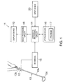
- FIG. 1 schematically shows the configuration of a golf swing analysis device (motion analysis device) 11 according to an embodiment of the invention.
- An inertial sensor 12 is connected to the golf swing analysis device 11.
- an acceleration sensor and a gyro sensor are incorporated in the inertial sensor 12.
- the acceleration sensor can detect acceleration in each of three axial directions that are orthogonal to each other.
- the gyro sensor can detect angular velocity about each of the three axes that are orthogonal to each other.
- the inertial sensor 12 outputs a detection signal.
- the acceleration and angular velocity on each axis are specified by the detection signal.
- the acceleration sensor and the gyro sensor detect information of acceleration and velocity relatively accurately.
- the inertial sensor 12 is mounted on a golf club (sporting gear) 13.
- the golf club 13 has a shaft 13a and a grip 13b.
- the grip 13b is held by the hands.
- the grip 13b is formed coaxially with the axis of the shaft 13a.
- a club head 13c is connected to the distal end of the shaft 13a.
- the inertial sensor 12 is mounted on the shaft 13a or the grip 13b of the golf club 13.
- the shaft 13a refers to a stick-like portion up to the club head 13c, including the grip 13b. It is sufficient that the inertial sensor 12 is fixed to the golf club 13 in a relatively non-movable manner.
- one of the detection axes of the inertial sensor 12 is aligned with the axis of the shaft 13a.
- Another one of the detection axes of the inertial sensor 12 is aligned with the direction of the face (ball hitting surface) of the club head 13c.
- the golf swing analysis device 11 has an arithmetic processing circuit 14.
- the inertial sensor 12 is connected to the arithmetic processing circuit 14.
- a predetermined interface circuit 15 is connected to the arithmetic processing circuit 14.
- the interface circuit 15 may be wired to the inertial sensor 12 or wirelessly connected to the inertial sensor 12.
- a detection signal is inputted to the arithmetic processing circuit 14 from the inertial sensor 12.
- a storage device 16 is connected to the arithmetic processing circuit 14.
- a golf swing analysis software program (motion analysis program) 17 and related data are stored.
- the arithmetic processing circuit 14 executes the golf swing analysis software program 17 to realize a golf swing analysis method.
- the storage device 16 can include a DRAM (dynamic random access memory), a large-capacity storage unit, a non-volatile memory or the like.
- the golf swing analysis software program 17 is temporarily held when carrying out the golf swing analysis method.
- the large-capacity storage unit such as a hard disk drive (HDD)
- the golf swing analysis software program 17 and data are saved.
- BIOS basic input/output system
- the arithmetic processing circuit 14 calculates a moving trajectory of a site of interest on the golf club 13, for example, the club head 13c.
- An image processing circuit 18 is connected to the arithmetic processing circuit 14.
- the arithmetic processing circuit 14 sends predetermined image data to the image processing circuit 18.
- a display device 19 is connected to the image processing circuit 18.
- a predetermined interface circuit (not shown) is connected to the image processing circuit 18.
- the image processing circuit 18 sends an image signal to the display device 19, according to the image data inputted thereto.
- An image specified by the image signal is displayed on the screen of the display device 19.
- a moving trajectory of the club head 13c is displayed.
- As the display device 19, a liquid crystal display or another type of flat panel display is used.
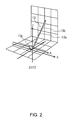
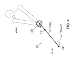
- a three-dimensional motion analysis model 26 shown in FIG. 4 is constructed according to an absolute reference coordinate system (world coordinate system) ⁇ XYZ.
- the coordinate axes forming the absolute reference coordinate system ⁇ XYZ are expressed as X-axis, Y-axis and Z-axis.
- the Z-axis in the absolute reference coordinate system ⁇ XYZ is in vertical direction.
- the X-axis in parallel to a target direction A that intersects with the face of the club head 13c.
- the Y-axis, orthogonal to the X-axis and Z-axis, is parallel to the direction of depth.
- ⁇ s of the inertial sensor 12 as shown in FIG.
- the y-axis is in the direction of the longitudinal axis in which the shaft 13a extends.
- the x-axis is parallel to the target direction A, similarly to the X-axis.
- the z-axis, orthogonal to the x-axis and y-axis, is in the orthogonal downward direction to the shaft 13a.
- the origin of the local coordinate system ⁇ s is set to the origin of the detection axes of the inertial sensor 12.
- the coordinate axes forming the local coordinate system ⁇ s are expressed as x-axis, y-axis and z-axis.
- a bar 27 in the three-dimensional motion analysis model 26 is point-constrained at a support 28.
- the bar 27 acts as a pendulum three-dimensionally about the support 28.
- the position of the support 28 can be moved.
- the position of the distal end 13c is specified.
- the three-dimensional motion analysis model 26 is equivalent to a modeling of the golf club 13 at the time of a swing.
- the pendulum bar 27 projects the shaft 13a of the golf club 13.
- the support 28 of the bar 27 projects the grip 13b.
- the inertial sensor 12 is fixed on the shaft 13a.
- the inertial sensor 12 outputs an acceleration signal and an angular velocity signal. As the acceleration signal, an acceleration signal including gravitational acceleration g is outputted.
- the arithmetic processing circuit 14 similarly fixes the local coordinate system ⁇ s shown in FIG. 3 to the inertial sensor 12. According to the local coordinate system ⁇ s shown in FIG. 3 , the position lsh of the club head 13c is specified by (0, l shy , 0), as shown in FIG. 4 .
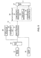
- FIG. 5 schematically shows the configuration of the arithmetic processing circuit 14 according to an embodiment.
- the arithmetic processing circuit 14 has, for example, a swing trajectory calculation unit 31 as a motion analysis unit.
- the swing trajectory calculation unit 31 is connected to the inertial sensor 12.
- An output signal is supplied to the swing trajectory calculation unit 31 from the inertial sensor 12.
- the output from the inertial sensor 12 includes acceleration detected along each of the three orthogonal axes and angular velocity detected about each of the three orthogonal axes.
- the swing trajectory calculation unit 31 detects the position and posture of the golf club 13 on the basis of the output from the inertial sensor 12 and calculates moving trajectories of the golf club and the subject's arms, using various methods.
- the arithmetic processing circuit 14 has an image data generation unit 34.
- the image data generation unit 34 is connected to the swing trajectory calculation unit 31. An output signal is supplied to the image data generation unit 34 from the swing trajectory calculation unit 31.
- the image data generation unit 34 has a moving trajectory image generation unit 35, an inverted image generation unit 36, and a coincidence determination unit 36A.
- the moving trajectory image generation unit 35 generates an image that visually shows a moving trajectory of the golf club 13 on the basis of the position and posture of the golf club 13.
- the inverted image generation unit 36 generates an inverted image formed by inverting an image.
- the coincidence determination unit 36A determines whether dominant hand information (first and second dominant hand information) added to two pieces of motion analysis information (first and second motion analysis information) coincides with each other, and supplies the result of the determination to the inverted image generation unit 36.
- the arithmetic processing circuit 14 has a drawing unit 37.
- the drawing unit 37 is connected to the image data generation unit 34. Image data is supplied to the drawing unit 37 from the image data generation unit 34.
- the drawing unit 37 draws an image that visually shows a moving trajectory of the golf club 13 on the basis of an output signal from the moving trajectory image generation unit 35.
- the drawing unit 37 also draws an inverted image on the basis of an output signal from the inverted image generation unit 36.
- the arithmetic processing circuit 14 receives an output signal from the inertial sensor 12.
- a sensor output storage unit 38 can be provided on the subsequent stage to the interface 15, as a receiving unit for an output signal from the inertial sensor 12.
- An output signal from the inertial sensor 12 is stored in the sensor output storage unit 38.
- a determination unit 39 is connected to the sensor output storage unit 38.
- the determination unit 39 determines the dominant hand of the subject on the basis of an output from the inertial sensor 12.
- the dominant hand information of the subject determined by the determination unit 39 is outputted to the swing trajectory calculation unit 31.
- the swing trajectory calculation unit 31 adds the dominant hand information of the subject to motion analysis information such as position information or the like of the club head 13c.
- FIG. 6 shows an example of display in which a swing trajectory RS of the club head 13c of the golf club 13 formed by a right-handed subject and a swing trajectory LS of the club head 13c of the golf club 13 formed by a left-handed subject are projected on an X-Z plane in the absolute coordinate system ⁇ XYZ or displayed three-dimensionally and then viewed straight from the lateral side.
- the point of intersection O between the X-axis and Y-axis is at the origin on the X-axis, which is the address position (impact position) of the club head 13c.
- the swing trajectory RS and the swing trajectory LS are in the relation of mirror inversion about a reference plane including the Z-axis passing through the origin O.
- the swing trajectory RS and the swing trajectory LS are substantially in the relation of mirror images to each other about the reference plane, due to the difference in the dominant hand between the subjects.
- the determination unit 39 automatically determines whether the subject is right-handed or left-handed on the basis of an output from the inertial sensor 12.
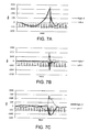
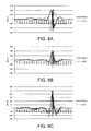
- FIGS. 7A to 7C and FIGS. 8A to 8C show time series data of six components, respectively, as an output from the inertial sensor 12.
- FIGS. 7A to 7C show time series data of angular velocity about the x-axis, y-axis and z-axis of a three-axis angular velocity sensor.
- FIGS. 8A to 8C show time series data of acceleration in the direction of the x-axis, y-axis and z-axis of a three-axis acceleration sensor.
- the angular velocity data is considered.
- the angular velocity about the z-axis shown in FIG. 7C manifests the inverted relation between right-handedness and left-handedness most notably.
- the reason for this is clear from FIG. 3 .
- the output data from the inertial sensor 12 is gathered about the three axes xyz in the local coordinate system ⁇ s shown in FIG. 3 as references.
- a turn in the R1 direction or R2 direction is the greatest motion and the rotation axis of the motion is the z-axis. That is, the motion of the club head 13c in a swing is a motion accompanying angular velocity about the z-axis.
- the angular velocity about the z-axis shown in FIG. 7C shows the relation in which the positive and negative are inverted between right-handedness and left-handedness.
- the angular velocity about the x-axis shown in FIG. 7A is almost the same between right-handedness and left-handedness.
- the sign is substantially inverted between right-handedness and left-handedness.
- the degree of inversion varies depending on the swing.
- the determination unit 39 is able to determine whether the subject is right-handed or left-handed on the basis of the angular velocity data from the inertial sensor 12, and is sufficiently able to determine whether the subject is right-handed or left-handed particularly on the basis of the time series data of angular velocity about the z-axis shown in FIG. 7C .
- the acceleration in the x-axis direction shown in FIG. 8A manifests the inverted relation between right-handedness and left-handedness most notably.
- the reason for this is clear from FIG. 3 .
- the x-axis parallel to the target direction A is the direction of a tangent line for a swing turn. Therefore, a swing turn is a motion in which the acceleration on the x-axis is the greatest of the three axes. That is, the motion of the club head 13c in a swing is a motion accompanying acceleration in the x-axis direction.
- the acceleration in the x-axis direction shown in FIG. 8A shows the relation in which the positive and negative are inverted between right-handedness and left-handedness.
- the determination unit 39 is able to determine whether the subject is right-handed or left-handed on the basis of the acceleration data from the inertial sensor 12, and is sufficiently able to determine whether the subject is right-handed or left-handed particularly on the basis of the time series data of acceleration parallel to the x-axis shown in FIG. 8A .
- Motion analysis information corresponding to one (for example, LS) of motions paired with each other (RS, LS) that form mirror images due to the difference in the dominant hand between the subjects shown in FIG. 6 is calculated by the swing trajectory calculation unit 31 on the basis of an output from the inertial sensor 12 and inputted to the inverted image generation unit 36 shown in FIG. 5 .
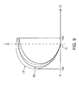
- the inverted image generation unit 36 inverts the sign (+, -) of the value of the one motion analysis information and thus enables one (for example, LS) of motions paired with each other (RS, LS) to be displayed as an inverted image (/LS) as shown in FIG. 9 .
- one (for example, LS) of motions paired with each other (RS, LS) is displayed in an inverted direction on the side where the other (RS) of the motions paired with each other (RS, LS) is displayed. That is, for example, a motion carried out by a left-handed person is displayed in the same direction as an image of a motion carried out by a right-handed person.
- the motion carried out by the left-handed person and the motion carried out by the right-handed person can be compared with each other more easily, and motion analysis becomes easier.
- first motion analysis information and second motion analysis information are calculated by the swing trajectory calculation unit 31, using an output from the inertial sensor 12.
- the inverted image generation unit 36 of the image data generation unit 34 inverts one (for example, LS) of the first motion analysis information and the second motion analysis information and leaves the other (RS) non-inverted, and thus enables the inverted image of the one (for example, /LS) and the non-inverted image (RS) of the other (for example, RS), of the motions paired with each other (RS, LS), to be superimposed together as these images are displayed on the screen as shown in FIG. 9 .
- dominant hands are determined using an output from the inertial sensor 12, and if the dominant hands are different, the inverted image generation unit 36 inverts the sign (+, -) of the value of one motion analysis information, and the one (for example, LS) of the motions paired with each other (RS, LS) is displayed as an inverted image (/LS) as shown in FIG. 9 .
- image data may be generated without inverting the sign of the value of motion analysis information, and the image data of one of the swing trajectories may be inverted if the dominant hands are determined as different.
- the coincidence determination unit 36A of the image data generation unit 34 can determine whether images are of different dominant hands or not. If the dominant hand information added to the motion analysis information does not coincide between the two images, the coincidence determination unit 36A can instruct the inverted image generation unit 36 to invert one of the images.
- the inverted image generation unit 36 inverts the sign of a position coordinate on the screen.
- the coordinate +Xa of the image LS shown in FIG. 6 has its sign inverted to the coordinate -Xa in the inverted image /LS shown in FIG. 9 .
- the coordinate -Xb of the image LS shown in FIG. 6 has its sign inverted to the coordinate +Xb in the inverted image /LS shown in FIG. 9 .
- an inverted image can be easily generated, simply by inverting the sign of the X-coordinate in the absolute reference coordinate system (world coordinate system) ⁇ XYZ.
- the configurations and operations of the inertial sensor 12, the arithmetic processing circuit 14, the three-dimensional motion analysis model 26, the swing trajectory calculation unit 31, the image data generation unit 34 , the moving trajectory image generation unit 35, the inverted image generation unit 36, the coincidence determination unit 36A, the storage unit 38 and the determination unit 39 or the like are not limited to those described in the embodiment, and various modifications can be made.
- the motion analysis to which the invention is applied is not limited to golf and can also be suitably carried out particularly with hitting or striking tools used in tennis, table tennis and the like.
Applications Claiming Priority (1)
| Application Number | Priority Date | Filing Date | Title |
|---|---|---|---|
| JP2013242192A JP2015100478A (ja) | 2013-11-22 | 2013-11-22 | 運動解析方法、運動解析表示方法、運動解析装置および運動解析プログラム |
Publications (1)
| Publication Number | Publication Date |
|---|---|
| EP2876625A1 true EP2876625A1 (fr) | 2015-05-27 |
Family
ID=51945748
Family Applications (1)
| Application Number | Title | Priority Date | Filing Date |
|---|---|---|---|
| EP14194045.2A Withdrawn EP2876625A1 (fr) | 2013-11-22 | 2014-11-20 | Procédé d'analyse de mouvement, procédé d'affichage d'analyse de mouvement et dispositif d'analyse de mouvement |
Country Status (4)
| Country | Link |
|---|---|
| US (1) | US9536319B2 (fr) |
| EP (1) | EP2876625A1 (fr) |
| JP (1) | JP2015100478A (fr) |
| CN (1) | CN104645582A (fr) |
Cited By (1)
| Publication number | Priority date | Publication date | Assignee | Title |
|---|---|---|---|---|
| ES2608707A1 (es) * | 2015-10-07 | 2017-04-12 | Miguel Ángel ANDRADE SÁNCHEZ | Sistema de captación y análisis de imagen |
Families Citing this family (1)
| Publication number | Priority date | Publication date | Assignee | Title |
|---|---|---|---|---|
| US10768196B2 (en) | 2016-12-19 | 2020-09-08 | Huami Inc. | Determine wearing position of a wearable device |
Citations (6)
| Publication number | Priority date | Publication date | Assignee | Title |
|---|---|---|---|---|
| US20030190972A1 (en) * | 2002-01-07 | 2003-10-09 | Townsend Marshall O. | Golf swing training template |
| US20060166737A1 (en) * | 2005-01-26 | 2006-07-27 | Bentley Kinetics, Inc. | Method and system for athletic motion analysis and instruction |
| US20070135225A1 (en) * | 2005-12-12 | 2007-06-14 | Nieminen Heikki V | Sport movement analyzer and training device |
| JP2008073210A (ja) | 2006-09-21 | 2008-04-03 | Seiko Epson Corp | ゴルフクラブ、そのスイング評価支援装置 |
| US20130005496A1 (en) * | 2003-10-09 | 2013-01-03 | William B. Priester | Multi-Rotor Apparatus and Method for Motion Sculpting |
| US20130072316A1 (en) * | 2011-05-27 | 2013-03-21 | Acushnet Company | Swing measurement golf club with sensors |
Family Cites Families (21)
| Publication number | Priority date | Publication date | Assignee | Title |
|---|---|---|---|---|
| US5984798A (en) * | 1998-08-27 | 1999-11-16 | Gilmour; Alf J. | Method and apparatus for achieving an improved golf swing |
| JP2004164563A (ja) * | 2002-09-26 | 2004-06-10 | Toshiba Corp | 画像解析方法、画像解析装置、画像解析プログラム |
| JP2005034195A (ja) * | 2003-07-15 | 2005-02-10 | Canon Inc | 講習支援システム及び講習支援方法 |
| US20050054457A1 (en) * | 2003-09-08 | 2005-03-10 | Smartswing, Inc. | Method and system for golf swing analysis and training |
| US7641565B2 (en) * | 2006-06-12 | 2010-01-05 | Wintriss Engineering Corporation | Method and apparatus for detecting the placement of a golf ball for a launch monitor |
| US8371962B2 (en) | 2007-09-28 | 2013-02-12 | Karsten Manufacturing Corporation | Methods apparatus, and systems to custom fit golf clubs |
| US8444509B2 (en) | 2007-09-28 | 2013-05-21 | Karsten Manufacturing Corporation | Methods, apparatus, and systems to custom fit golf clubs |
| US8360899B2 (en) | 2007-09-28 | 2013-01-29 | Karsten Manfacturing Corporation | Methods, apparatus, and systems to custom fit golf clubs |
| US20100151956A1 (en) | 2007-09-28 | 2010-06-17 | Swartz Gregory J | Methods, apparatus, and systems to custom fit golf clubs |
| JP4515510B2 (ja) | 2008-03-13 | 2010-08-04 | みずほ情報総研株式会社 | 録画管理システム、録画管理方法及び録画管理プログラム |
| JP5574609B2 (ja) | 2008-03-19 | 2014-08-20 | カーステン マニュファクチュアリング コーポレーション | ゴルフクラブのカスタムフィッティングのための方法、装置、及びシステム |
| JP5367492B2 (ja) * | 2009-07-31 | 2013-12-11 | ダンロップスポーツ株式会社 | ゴルフクラブの評価方法 |
| US20110124445A1 (en) * | 2009-11-20 | 2011-05-26 | Uehling Iii Gordon A | Video-based system for tennis training |
| JP5424841B2 (ja) | 2009-12-08 | 2014-02-26 | ダンロップスポーツ株式会社 | ゴルフスイング診断システム |
| JP4590010B1 (ja) * | 2009-12-14 | 2010-12-01 | エンパイア テクノロジー ディベロップメント エルエルシー | 動作解析装置、および動作解析方法 |
| US8644884B2 (en) * | 2011-08-04 | 2014-02-04 | Qualcomm Incorporated | Sensor-based user interface control |
| JP2013111206A (ja) | 2011-11-29 | 2013-06-10 | Kddi Corp | 加速度センサ及び地磁気センサを用いて打撃前の構え姿勢を検出する携帯端末、プログラム及び方法 |
| JP5915148B2 (ja) * | 2011-12-16 | 2016-05-11 | セイコーエプソン株式会社 | 運動解析方法及び運動解析装置 |
| KR101398778B1 (ko) * | 2012-03-30 | 2014-05-27 | 스미토모 고무 고교 가부시키가이샤 | 골프 클럽의 샤프트의 피팅 방법 |
| FR2990356A1 (fr) * | 2012-05-10 | 2013-11-15 | Movea | Procede d'analyse du jeu d'un utilisateur d'une raquette |
| US8998717B2 (en) * | 2013-01-17 | 2015-04-07 | Ppg Technologies, Inc. | Device and method for reconstructing and analyzing motion of a rigid body |
-
2013
- 2013-11-22 JP JP2013242192A patent/JP2015100478A/ja not_active Withdrawn
-
2014
- 2014-11-06 US US14/534,594 patent/US9536319B2/en active Active
- 2014-11-19 CN CN201410666131.3A patent/CN104645582A/zh active Pending
- 2014-11-20 EP EP14194045.2A patent/EP2876625A1/fr not_active Withdrawn
Patent Citations (6)
| Publication number | Priority date | Publication date | Assignee | Title |
|---|---|---|---|---|
| US20030190972A1 (en) * | 2002-01-07 | 2003-10-09 | Townsend Marshall O. | Golf swing training template |
| US20130005496A1 (en) * | 2003-10-09 | 2013-01-03 | William B. Priester | Multi-Rotor Apparatus and Method for Motion Sculpting |
| US20060166737A1 (en) * | 2005-01-26 | 2006-07-27 | Bentley Kinetics, Inc. | Method and system for athletic motion analysis and instruction |
| US20070135225A1 (en) * | 2005-12-12 | 2007-06-14 | Nieminen Heikki V | Sport movement analyzer and training device |
| JP2008073210A (ja) | 2006-09-21 | 2008-04-03 | Seiko Epson Corp | ゴルフクラブ、そのスイング評価支援装置 |
| US20130072316A1 (en) * | 2011-05-27 | 2013-03-21 | Acushnet Company | Swing measurement golf club with sensors |
Cited By (2)
| Publication number | Priority date | Publication date | Assignee | Title |
|---|---|---|---|---|
| ES2608707A1 (es) * | 2015-10-07 | 2017-04-12 | Miguel Ángel ANDRADE SÁNCHEZ | Sistema de captación y análisis de imagen |
| WO2017060548A1 (fr) * | 2015-10-07 | 2017-04-13 | Andrade Sánchez Miguel Ángel | Système de capture et d'analyse d'image |
Also Published As
| Publication number | Publication date |
|---|---|
| JP2015100478A (ja) | 2015-06-04 |
| US20150146933A1 (en) | 2015-05-28 |
| US9536319B2 (en) | 2017-01-03 |
| CN104645582A (zh) | 2015-05-27 |
Similar Documents
| Publication | Publication Date | Title |
|---|---|---|
| US10478707B2 (en) | Motion analysis method and motion analysis device | |
| JP6467766B2 (ja) | 運動解析方法、運動解析装置および運動解析プログラム | |
| US9717969B2 (en) | Motion analyzing apparatus and motion analyzing program | |
| US20150012240A1 (en) | Motion analysis device | |
| JP2015077351A (ja) | 運動解析方法、運動解析装置および運動解析プログラム | |
| JP2015002910A5 (fr) | ||
| KR20140148298A (ko) | 운동 해석 방법 및 운동 해석 장치 | |
| JP2016013302A (ja) | 運動解析方法、プログラム及び運動解析装置 | |
| JP6168279B2 (ja) | 解析制御装置、運動解析システム、プログラム、記録媒体および方位合わせ方法 | |
| JP2015173862A5 (fr) | ||
| US20150119159A1 (en) | Motion analyzing apparatus, motion analyzing method, and motion analyzing program | |
| US9536319B2 (en) | Motion analysis method, motion analysis display method, and motion analysis device | |
| US11224787B2 (en) | Swing measurement device, swing measurement method, and swing measurement program | |
| JP6428815B2 (ja) | 運動解析装置、運動解析システムおよび運動解析方法 | |
| JP6311727B2 (ja) | 表示装置及び表示方法並びに表示プログラム | |
| JP2015100567A (ja) | 方位角キャリブレーション方法、運動解析装置、および方位角キャリブレーションプログラム | |
| JP6255738B2 (ja) | 運動解析装置および運動解析プログラム並びに表示方法 | |
| JP2015134008A (ja) | 運動解析方法、運動解析装置及び運動解析プログラム | |
| JP2019004979A (ja) | 打具の挙動の解析装置 | |
| JP2016101314A (ja) | フォーム解析装置、フォーム解析システム、フォーム解析方法、およびフォーム解析プログラム |
Legal Events
| Date | Code | Title | Description |
|---|---|---|---|
| PUAI | Public reference made under article 153(3) epc to a published international application that has entered the european phase |
Free format text: ORIGINAL CODE: 0009012 |
|
| 17P | Request for examination filed |
Effective date: 20141120 |
|
| AK | Designated contracting states |
Kind code of ref document: A1 Designated state(s): AL AT BE BG CH CY CZ DE DK EE ES FI FR GB GR HR HU IE IS IT LI LT LU LV MC MK MT NL NO PL PT RO RS SE SI SK SM TR |
|
| AX | Request for extension of the european patent |
Extension state: BA ME |
|
| R17P | Request for examination filed (corrected) |
Effective date: 20151112 |
|
| RBV | Designated contracting states (corrected) |
Designated state(s): AL AT BE BG CH CY CZ DE DK EE ES FI FR GB GR HR HU IE IS IT LI LT LU LV MC MK MT NL NO PL PT RO RS SE SI SK SM TR |
|
| 17Q | First examination report despatched |
Effective date: 20170309 |
|
| STAA | Information on the status of an ep patent application or granted ep patent |
Free format text: STATUS: THE APPLICATION IS DEEMED TO BE WITHDRAWN |
|
| 18D | Application deemed to be withdrawn |
Effective date: 20170720 |