EP2876232B1 - Modularer Unterstellplatz - Google Patents
Modularer Unterstellplatz Download PDFInfo
- Publication number
- EP2876232B1 EP2876232B1 EP13194296.3A EP13194296A EP2876232B1 EP 2876232 B1 EP2876232 B1 EP 2876232B1 EP 13194296 A EP13194296 A EP 13194296A EP 2876232 B1 EP2876232 B1 EP 2876232B1
- Authority
- EP
- European Patent Office
- Prior art keywords
- modules
- car shed
- base plate
- coupled
- rear wall
- Prior art date
- Legal status (The legal status is an assumption and is not a legal conclusion. Google has not performed a legal analysis and makes no representation as to the accuracy of the status listed.)
- Active
Links
- 239000011521 glass Substances 0.000 claims description 16
- 230000006698 induction Effects 0.000 claims description 13
- 238000010438 heat treatment Methods 0.000 claims description 12
- 238000004146 energy storage Methods 0.000 claims description 11
- 229920003229 poly(methyl methacrylate) Polymers 0.000 claims description 4
- 239000004926 polymethyl methacrylate Substances 0.000 claims description 4
- 229910052782 aluminium Inorganic materials 0.000 description 4
- XAGFODPZIPBFFR-UHFFFAOYSA-N aluminium Chemical compound [Al] XAGFODPZIPBFFR-UHFFFAOYSA-N 0.000 description 4
- 230000002093 peripheral effect Effects 0.000 description 4
- 101100498160 Mus musculus Dach1 gene Proteins 0.000 description 3
- 238000004519 manufacturing process Methods 0.000 description 2
- 230000003247 decreasing effect Effects 0.000 description 1
- 230000001419 dependent effect Effects 0.000 description 1
- 238000011161 development Methods 0.000 description 1
- 230000018109 developmental process Effects 0.000 description 1
- 230000005611 electricity Effects 0.000 description 1
- 238000005286 illumination Methods 0.000 description 1
- 230000001939 inductive effect Effects 0.000 description 1
- 238000009434 installation Methods 0.000 description 1
- 229910052751 metal Inorganic materials 0.000 description 1
- 239000002184 metal Substances 0.000 description 1
- 239000000843 powder Substances 0.000 description 1
- 230000005855 radiation Effects 0.000 description 1
- 239000002023 wood Substances 0.000 description 1
Images

Classifications
-
- E—FIXED CONSTRUCTIONS
- E04—BUILDING
- E04H—BUILDINGS OR LIKE STRUCTURES FOR PARTICULAR PURPOSES; SWIMMING OR SPLASH BATHS OR POOLS; MASTS; FENCING; TENTS OR CANOPIES, IN GENERAL
- E04H6/00—Buildings for parking cars, rolling-stock, aircraft, vessels or like vehicles, e.g. garages
- E04H6/02—Small garages, e.g. for one or two cars
-
- A—HUMAN NECESSITIES
- A61—MEDICAL OR VETERINARY SCIENCE; HYGIENE
- A61H—PHYSICAL THERAPY APPARATUS, e.g. DEVICES FOR LOCATING OR STIMULATING REFLEX POINTS IN THE BODY; ARTIFICIAL RESPIRATION; MASSAGE; BATHING DEVICES FOR SPECIAL THERAPEUTIC OR HYGIENIC PURPOSES OR SPECIFIC PARTS OF THE BODY
- A61H33/00—Bathing devices for special therapeutic or hygienic purposes
- A61H33/06—Artificial hot-air or cold-air baths; Steam or gas baths or douches, e.g. sauna or Finnish baths
- A61H33/066—Cabins therefor
-
- E—FIXED CONSTRUCTIONS
- E04—BUILDING
- E04H—BUILDINGS OR LIKE STRUCTURES FOR PARTICULAR PURPOSES; SWIMMING OR SPLASH BATHS OR POOLS; MASTS; FENCING; TENTS OR CANOPIES, IN GENERAL
- E04H1/00—Buildings or groups of buildings for dwelling or office purposes; General layout, e.g. modular co-ordination or staggered storeys
- E04H1/12—Small buildings or other erections for limited occupation, erected in the open air or arranged in buildings, e.g. kiosks, waiting shelters for bus stops or for filling stations, roofs for railway platforms, watchmen's huts or dressing cubicles
- E04H1/1205—Small buildings erected in the open air
- E04H1/1211—Waiting shelters for bus stops
-
- E—FIXED CONSTRUCTIONS
- E04—BUILDING
- E04H—BUILDINGS OR LIKE STRUCTURES FOR PARTICULAR PURPOSES; SWIMMING OR SPLASH BATHS OR POOLS; MASTS; FENCING; TENTS OR CANOPIES, IN GENERAL
- E04H6/00—Buildings for parking cars, rolling-stock, aircraft, vessels or like vehicles, e.g. garages
- E04H6/005—Garages for vehicles on two wheels
-
- H—ELECTRICITY
- H01—ELECTRIC ELEMENTS
- H01L—SEMICONDUCTOR DEVICES NOT COVERED BY CLASS H10
- H01L31/00—Semiconductor devices sensitive to infrared radiation, light, electromagnetic radiation of shorter wavelength or corpuscular radiation and specially adapted either for the conversion of the energy of such radiation into electrical energy or for the control of electrical energy by such radiation; Processes or apparatus specially adapted for the manufacture or treatment thereof or of parts thereof; Details thereof
- H01L31/04—Semiconductor devices sensitive to infrared radiation, light, electromagnetic radiation of shorter wavelength or corpuscular radiation and specially adapted either for the conversion of the energy of such radiation into electrical energy or for the control of electrical energy by such radiation; Processes or apparatus specially adapted for the manufacture or treatment thereof or of parts thereof; Details thereof adapted as photovoltaic [PV] conversion devices
- H01L31/042—PV modules or arrays of single PV cells
-
- H—ELECTRICITY
- H02—GENERATION; CONVERSION OR DISTRIBUTION OF ELECTRIC POWER
- H02S—GENERATION OF ELECTRIC POWER BY CONVERSION OF INFRARED RADIATION, VISIBLE LIGHT OR ULTRAVIOLET LIGHT, e.g. USING PHOTOVOLTAIC [PV] MODULES
- H02S40/00—Components or accessories in combination with PV modules, not provided for in groups H02S10/00 - H02S30/00
- H02S40/30—Electrical components
- H02S40/38—Energy storage means, e.g. batteries, structurally associated with PV modules
-
- H—ELECTRICITY
- H02—GENERATION; CONVERSION OR DISTRIBUTION OF ELECTRIC POWER
- H02S—GENERATION OF ELECTRIC POWER BY CONVERSION OF INFRARED RADIATION, VISIBLE LIGHT OR ULTRAVIOLET LIGHT, e.g. USING PHOTOVOLTAIC [PV] MODULES
- H02S40/00—Components or accessories in combination with PV modules, not provided for in groups H02S10/00 - H02S30/00
- H02S40/40—Thermal components
- H02S40/44—Means to utilise heat energy, e.g. hybrid systems producing warm water and electricity at the same time
-
- E—FIXED CONSTRUCTIONS
- E04—BUILDING
- E04H—BUILDINGS OR LIKE STRUCTURES FOR PARTICULAR PURPOSES; SWIMMING OR SPLASH BATHS OR POOLS; MASTS; FENCING; TENTS OR CANOPIES, IN GENERAL
- E04H1/00—Buildings or groups of buildings for dwelling or office purposes; General layout, e.g. modular co-ordination or staggered storeys
- E04H1/12—Small buildings or other erections for limited occupation, erected in the open air or arranged in buildings, e.g. kiosks, waiting shelters for bus stops or for filling stations, roofs for railway platforms, watchmen's huts or dressing cubicles
- E04H2001/1288—Sauna cabins
-
- Y—GENERAL TAGGING OF NEW TECHNOLOGICAL DEVELOPMENTS; GENERAL TAGGING OF CROSS-SECTIONAL TECHNOLOGIES SPANNING OVER SEVERAL SECTIONS OF THE IPC; TECHNICAL SUBJECTS COVERED BY FORMER USPC CROSS-REFERENCE ART COLLECTIONS [XRACs] AND DIGESTS
- Y02—TECHNOLOGIES OR APPLICATIONS FOR MITIGATION OR ADAPTATION AGAINST CLIMATE CHANGE
- Y02E—REDUCTION OF GREENHOUSE GAS [GHG] EMISSIONS, RELATED TO ENERGY GENERATION, TRANSMISSION OR DISTRIBUTION
- Y02E10/00—Energy generation through renewable energy sources
- Y02E10/50—Photovoltaic [PV] energy
-
- Y—GENERAL TAGGING OF NEW TECHNOLOGICAL DEVELOPMENTS; GENERAL TAGGING OF CROSS-SECTIONAL TECHNOLOGIES SPANNING OVER SEVERAL SECTIONS OF THE IPC; TECHNICAL SUBJECTS COVERED BY FORMER USPC CROSS-REFERENCE ART COLLECTIONS [XRACs] AND DIGESTS
- Y02—TECHNOLOGIES OR APPLICATIONS FOR MITIGATION OR ADAPTATION AGAINST CLIMATE CHANGE
- Y02E—REDUCTION OF GREENHOUSE GAS [GHG] EMISSIONS, RELATED TO ENERGY GENERATION, TRANSMISSION OR DISTRIBUTION
- Y02E10/00—Energy generation through renewable energy sources
- Y02E10/60—Thermal-PV hybrids
-
- Y—GENERAL TAGGING OF NEW TECHNOLOGICAL DEVELOPMENTS; GENERAL TAGGING OF CROSS-SECTIONAL TECHNOLOGIES SPANNING OVER SEVERAL SECTIONS OF THE IPC; TECHNICAL SUBJECTS COVERED BY FORMER USPC CROSS-REFERENCE ART COLLECTIONS [XRACs] AND DIGESTS
- Y02—TECHNOLOGIES OR APPLICATIONS FOR MITIGATION OR ADAPTATION AGAINST CLIMATE CHANGE
- Y02E—REDUCTION OF GREENHOUSE GAS [GHG] EMISSIONS, RELATED TO ENERGY GENERATION, TRANSMISSION OR DISTRIBUTION
- Y02E70/00—Other energy conversion or management systems reducing GHG emissions
- Y02E70/30—Systems combining energy storage with energy generation of non-fossil origin
Definitions
- the invention relates to a modular parking space, in particular for vehicles, in particular electrically operated vehicles, or for use as a sauna and a solar module for use in a modular parking space according to the invention.
- Parking spaces for vehicles are usually referred to as a carport and often have the purpose to ensure the vehicle only a protection from above.
- Such carports are usually open at the side and consist only of a roof and a support structure. That's how it shows DE 20 2005 008 189 U1 a carport with a roof supported by a total of eight posts.
- Such carports have the disadvantage that they are provided on the one hand exclusively for the Unterstellen a vehicle and on the other hand that the size or width of the carport is not adaptable to individual needs, such as several vehicles or several different vehicles, such as an automobile and a Motorcycle, should be placed under.
- a cabin which can be assembled from floor modules, sidewall modules and roof modules.
- the assembly of the individual modules takes place with connecting means.
- a housing for vehicles which has an integrated power supply for charging a battery of a parked in the house vehicle.
- the roofing structure of the dwelling has photovoltaic elements coupled to a cache. Further, the dwelling has a power feed cable for connection to the vehicle.
- a housing is known that is composed of a number of modules.
- the roof of the housing is composed of a number of solar modules.
- the side walls of the housing may also be composed of a number of solar modules.
- a garage is known, wherein on the roof a photovoltaic system is arranged from a number of photovoltaic modules.
- the invention is therefore based on the object of providing a parking space, in particular for vehicles, in particular electrically operated vehicles, which on the one hand is flexibly expandable and on the other hand offers an overall improved functionality.
- the bottom plate or the roof can be widened so as to obtain a larger footprint, for example, a larger carport.
- a larger footprint for example, a larger carport.
- additional bottom plate modules and additional solar modules must be provided without the existing parking space must be completely replaced.
- this can be individually adapted to the underlindden vehicles, which ensures greater flexibility in terms of the usability of the parking space.
- the parking space according to the invention can be operated as self-sufficient, without power connections, such as from neighboring buildings, are needed.
- the parking space according to the invention can thus be placed on the "green field" to be able to store and charge, for example, electrically driven bicycles in remote regions, such as in the mountains.
- the individual modules may further comprise a back wall comprising a number of backplane modules connectable to the backplane. Again, only the required number of backplane modules must be used in the rear wall at an increase in the parking space.
- the solar modules, the bottom plate modules and the rear wall modules each have substantially the same width.
- the solar modules, the bottom plate modules and the rear wall modules each have substantially the same width.
- the individual modules further comprise a power storage device which can be coupled to the solar modules and which can be charged with the electrical energy provided by the solar modules.
- a power storage device which can be coupled to the solar modules and which can be charged with the electrical energy provided by the solar modules.
- subordinate and electrically operated vehicles such as electrically powered bicycles can also be charged at night by night can be obtained from the electricity storage device required for charging the power.
- subordinate electrically powered vehicles can be charged directly with the electrical power generated by the solar modules.
- the storage space according to the invention comprises charging means, which are coupled to the solar modules and / or to the power storage device and which are arranged on at least one side wall and / or on the rear wall and / or on or in the bottom plate and for charging a power storage at least one electrically powered vehicle are provided.
- charging means which are coupled to the solar modules and / or to the power storage device and which are arranged on at least one side wall and / or on the rear wall and / or on or in the bottom plate and for charging a power storage at least one electrically powered vehicle are provided.
- the charging means may comprise at least one socket or at least one power strip and / or at least one induction coil, which may cooperate with a secondary coil of an electrically operated vehicle.
- the induction coil can be coupled to the current storage device via the connection unit of the base plate module.
- An inserted bottom plate module only has to be connected to the solar modules or to the current storage device via the connection unit. Further measures are no longer necessary to ensure an inductive charging of an electrically operated vehicle. The cost of extending a parking space according to the invention is thereby significantly reduced.
- At least one socket or power strip is integrated in at least one rear wall module, wherein the rear wall module has a connection unit, via which the socket or power strip can be coupled to the solar modules and / or to the power storage device.
- the connection unit via which the socket or power strip can be coupled to the solar modules and / or to the power storage device.
- a solar module comprises a number of photovoltaic cells, which are supported by an at least partially circumferential frame, wherein at the back of the photovoltaic cells (the back is the side which is not facing the sun) and preferably spaced from the Photovoltaic cells, a light source and / or a heating means is arranged.
- the parking space can be lit and / or heated.
- the lighting means and / or the heating means are supported by the at least partially encircling frame.
- the lighting means comprise a number of LEDs and / or a surface illumination.
- the heating means may comprise infrared panels.
- a power storage device may be arranged in the frame, which is coupled to the photovoltaic cells and to the lighting means and / or to the heating means.
- the lighting means and / or the heating means can also be operated without additional power storage device when the parking space is used, for example, as a waiting area for a bus stop.
- the bulbs and / or the heating means can also be operated at night.
- LEDs can be arranged in the frame, the light of which can be coupled laterally into a glass pane, preferably an acrylic glass pane.
- the glass sheet is preferably designed so that a uniform scattering of the coupled-in light over the entire surface of the glass sheet is made possible.
- the glass pane may have a correspondingly machined surface.
- advertising surfaces can be arranged, which are provided for example with a backlight or as active display devices, such as a large display, designed.
- the backlight or the display can be operated with the electric current provided by the solar modules or with the electrical current stored in the current storage device.
- the front of the parking space may have a glass or a glass front, which is preferably completely closed.
- a glass or a glass front In this embodiment may be provided on a side wall, a door through which the parking space is accessible.
- an electric furnace may be provided, which is supplied with the electrical energy of the solar modules and / or with the electrical energy of the power storage device with power.
- the side walls and the bottom plate may be lined with wooden panels.
- the modular carport can be used as a modular sauna or sauna device, which has a glass front and is self-sufficient with energy.
- the sauna can be provided as an outdoor sauna, such as a hotel.
- the door provided in a side wall may be provided as a connecting door between the hotel building and the sauna.
- Fig. 1 shows a perspective view of a modular carport 10 according to the invention.
- the parking space 10 comprises a number of individual modules, which are assembled or assembled with suitable connecting means.
- the individual modules comprise a right side wall 20, a left side wall 21, a rear wall 22, a bottom plate 23 and a roof 25.
- the rear wall 22 can also be dispensed with.
- the side walls 20, 21 are configured in the embodiment shown here as full-surface walls. But you can also have recesses or recesses, such as windows or doors.
- the side walls 20, 21 and / or the rear wall 22 may be made of concrete or a metal, for example aluminum, be prepared. Particularly preferred may be used for the side walls 20, 21 and for the rear wall 22, a powder-coated aluminum sheet of different shades.
- advertising surfaces 40 may be arranged, wherein the advertising space can be arranged both outboard and inboard.
- advertising space for example, printed posters with a backlight or active advertising space, such as advertising displays, can be provided.
- the bottom plate 23 consists of a number of bottom plate modules 24, which preferably each have the same width b and the same depth. By juxtaposing a number of bottom plate modules 24, the bottom plate 23 can be manufactured.
- the bottom plate modules 24 may be joined together, for example, via a tongue and groove connection or via a dovetail connection.
- the rear wall 22 is formed by a number of backplane modules 26, with the backplane modules 26 also being assembled with suitable connection means.
- the roof 25 comprises a number of solar modules 30, which are also joined together by suitable connecting means.
- the roof 25 and the solar modules 30 are arranged slightly inclined in the direction of the rear wall 22, so that rainwater can flow to the rear. At the back of the parking space this can be provided a gutter.
- the solar modules 30 generate electric power with which electrically operated vehicles accommodated in the parking space can be charged.
- the parking space according to the invention has a number of loading means.
- Not according to the invention can at the Rear wall 22 may be provided a number of sockets or a power strip, which are coupled to the solar modules 30.
- a number of induction coils 55 which are likewise coupled to the solar modules 30, are provided in the base plate 23.
- the parking space additionally provides a power storage device 60, for example an accumulator.
- the current storage device 60 is coupled both to the solar modules 30 in order to charge the current storage device 60 with the electrical energy provided by the solar modules 30, as well as to the power strip 50 or to the induction coils 55. In low light conditions or at night, the electrical energy required for charging electrically operated vehicles can be obtained from the current storage device 60.
- the power storage device 60 may be integrated in the bottom plate 23 or, as in FIG Fig. 1 shown to be arranged below the bottom plate.
- the bottom plate modules 24 are each a number of induction coils integrated with the associated electronics.
- the bottom plate modules 24 each have a connection unit via which the induction coils or the electronics can be coupled to the solar modules 30 or to the current storage device 60.
- the parking space according to the invention can be expanded in a simple manner, whereby the possibility of inductively charging an additional electrically operated vehicle by inserting an additional floor panel module 24 (ie the or the underlying electrically powered vehicles can be charged wirelessly).
- the bottom plate modules 24 can be manufactured completely at the factory, so that in the manufacture of the parking space, the bottom plate modules only need to be assembled and connected.
- the sockets or socket strips 50 can likewise be integrated into the rear wall modules 26, so that the rear wall modules 26 can also be completely manufactured at the factory.
- the rear wall modules likewise have connecting means in order to connect the rear wall modules or the sockets and / or socket strips to the solar modules 30 or to the current storage device 60.
- the bottom plate modules 24, the rear wall modules 26 and the solar modules 30 each preferably have the same width b, so that when adjusting the size of the parking space 10 each have the same number of corresponding modules can be used or removed.
- the provided charging means 50, 55 or additional charging means may be provided to charge other electrical devices, such as a mobile phone wired or wireless.
- the loading means 50, 55 can be dispensed with, so that the storage space 10 according to the invention can also be used, for example, as a waiting area, for example for a bus stop.
- a lighting or a heater may be provided, which are supplied either directly from the solar modules or from the power storage device 60 with electrical energy.
- a modular parking space is provided, which can be increased or decreased by inserting or removing corresponding backplane modules, bottom plate modules and solar modules and is particularly easy to adapt to different needs.
- subordinate electrically powered vehicles such as e-bikes, electric scooters or electrically powered cars can be charged, even if no external power supply is available.
- storage areas according to the invention are particularly suitable in areas where there is no power supply, for example in the mountains.
- no consideration must be given to whether an external power supply is available, so that an inventive parking space, since it can be operated completely self-sufficient, can be placed at any arbitrary place.
- the modular parking space can also be used as a sauna or outdoor sauna.
- a glass pane is arranged on the front of the parking space or the front side is closed with a glass pane.
- On a side wall or on the rear wall may be provided a door through which the sauna can be entered.
- the interior of the parking space can be covered with wood or wooden panels.
- an electric furnace may be provided which is coupled to the solar modules and / or to the power storage device in order to supply the electric furnace with electrical energy.
- the sauna As a self-sufficient sauna, i. be operated without external power supply.
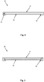
- Fig. 2 shows a cross section of a solar module 30 according to the invention, which can be used for producing a roof of a storage space according to the invention.
- This in Fig. 2 shown solar module 30 includes a number of photovoltaic cells 31, which are supported by an at least partially encircling frame 32.
- the frame 32 may be made of aluminum, for example.
- a lighting means 33 may be provided, which in turn is supported by the peripheral frame 32.
- a roof of a parking space according to the invention can be produced in a particularly simple manner, on the one hand provides electric power for charging electrically powered vehicles and on the other hand illuminates the interior of the parking space.
- the electrical energy for the operation of the luminous means 33 can be provided directly by the photovoltaic cells 31, or if the electrical energy provided by the photovoltaic cells 31 is insufficiently obtained from the energy storage device 60.
- a separate energy store may be provided in the frame 32, which is charged by the photovoltaic cells 31 and which, for example, provides the electrical energy for the lighting means 33 at night.
- the lighting means 33 can also be operated when no energy storage device 60 is provided at the parking space 10. This is particularly advantageous if the parking space 10 according to the invention is used, for example, as a bus shelter of a bus stop, where only sufficient electrical energy for the operation of the lighting means 33 must be provided.
- connecting means may be provided, via which a plurality of solar modules can be coupled together.
- connections can be provided with which the photovoltaic cells 31 of two coupled solar modules can be connected in series.
- a lighting means 33 for example, a number of light-emitting diodes (LED's) or a surface lighting can be provided.
- LED's light-emitting diodes
- a number of LEDs may be arranged in the peripheral frame 32, whose light is coupled on the edge side into a glass plate held by the frame 32.
- the glass plate is preferably designed so that the edge coupled-in light scattered evenly over the entire glass surface or decoupled.
- an acrylic glass pane may be provided, the surface of which is correspondingly roughened to ensure a uniform scattering of the coupled-in light.
- Fig. 3 shows an alternative embodiment of a solar module 30, wherein instead of the in Fig. 2 shown illuminant 33, a heater 35 is provided.
- the heater 35 may be configured, for example, as an infrared panel, which emits heat radiation downwards during operation.
- the heating means 35 can be supplied either directly via the photovoltaic cells 31 or via the energy storage device 60 or via an arranged in the surrounding frame 32 energy storage 34 with electric power.
- a solar module 30 has a number of bulbs and a number of heaters.
- a solar module according to Fig. 3 is particularly advantageous if the inventive modular parking space is used for example as a bus shelter of a bus stop.
Description
- Die Erfindung betrifft einen modularen Unterstellplatz, insbesondere für Fahrzeuge, insbesondere elektrisch betriebene Fahrzeuge, oder zur Verwendung als Sauna sowie ein Solarmodul zur Verwendung in einem erfindungsgemäßen modularen Unterstellplatz.
- Aus dem Stand der Technik sind eine Vielzahl von verschiedenen Unterstellplatzkonstruktionen, insbesondere für Fahrzeuge bekannt, wie beispielsweise aus der
DE 20 2005 008 189 U1 , oder aus derDE 295 15 728 U1 . - Unterstellplätze für Fahrzeuge werden meist als Carport bezeichnet und haben häufig den Zweck, für das Fahrzeug lediglich einen Schutz von oben zu gewährleisten. Solche Carports sind seitlich meist offen und bestehen nur aus einem Dach und einer Stützkonstruktion. So zeigt die
DE 20 2005 008 189 U1 ein Carport mit einem Dach, das von insgesamt acht Pfosten getragen wird. Solche Carports haben allerdings den Nachteil, dass sie einerseits ausschließlich für das Unterstellen eines Fahrzeuges vorgesehen sind und andererseits, dass die Größe bzw. Breite des Carports nicht an individuelle Bedürfnisse anpassbar ist, wenn etwa mehrere Fahrzeuge oder mehrere unterschiedliche Fahrzeuge, etwa ein Automobil und ein Motorrad, untergestellt werden sollen. - Ein weiterer Nachteil besteht darin, dass die aus dem Stand der Technik bekannten Carports keine Mittel zur Verfügung stellen, um einen Stromspeicher eines elektrisch betriebenen Fahrzeuges aufladen zu können. Hierfür muss das Fahrzeug meist an einem Stromanschluss, beispielsweise eines benachbarten Wohnhauses angeschlossen werden. Der Carport muss, sofern man ein Aufladen eines Stromspeichers eines abgestellten Fahrzeuges wünscht, in der Nähe eines Stromanschlusses errichtet werden, was einen flexiblen Einsatz eines Carports hinsichtlich des Aufstellortes erheblich einschränkt.
- Aus der
US 2007/0044391 A1 ist eine Hütte bekannt, die aus Bodenmodulen, Seitenwandmodulen und Dachmodulen zusammengebaut werden kann. Der Zusammenbau der einzelnen Module erfolgt mit Verbindungsmittel. - Aus der
DE 20 2009 016 950 U1 eine Behausung für Fahrzeuge bekannt, die eine integrierte Stromversorgung zum Aufladen eines Akkumulators eines in der Behausung abgestellten Fahrzeuges aufweist. Die Überdachungskonstruktion der Behausung weist Photovoltaikelemente auf, die mit einem Zwischenspeicher gekoppelt sind. Ferner weist die Behausung ein Stromeinspeisekabel auf, zum Anschluss an das Fahrzeug auf. - Aus der
CN 102 277 985 A ist ein Gehäuse bekannt, dass aus einer Anzahl von Modulen zusammengesetzt ist. Das Dach des Gehäuses ist aus einer Anzahl von Solarmodulen zusammengesetzt. Die Seitwände des Gehäuses können ebenfalls aus einer Anzahl von Solarmodulen zusammengesetzt sein. - Aus der
DE 20 2012 101 572 U1 ist eine Garage bekannt, wobei auf dem Dach eine Photovoltaikanlage aus einer Anzahl von Photovoltaikmodulen angeordnet ist. - Der Erfindung liegt daher die Aufgabe zugrunde, einen Unterstellplatz, insbesondere für Fahrzeuge, insbesondere elektrisch betriebene Fahrzeuge, bereitzustellen, der einerseits flexibel erweiterbar ist und andererseits eine insgesamt verbesserte Funktionalität bietet.
- Diese Aufgabe wird erfindungsgemäß durch einen modularen Unterstellplatz, insbesondere für Fahrzeuge, nach dem unabhängigen Anspruch gelöst. Vorteilhafte Ausgestaltungen und Weiterbildungen der Erfindung sind in den abhängigen Ansprüchen angegeben.
- Bereitgestellt wird demnach ein modularer Unterstellplatz, insbesondere für Fahrzeuge, bestehend aus Einzelmodulen, die mit Verbindungsmittel zum Unterstellplatz zusammenbaubar sind, wobei die Einzelmodule umfassen:
- eine Bodenplatte,
- zwei senkrecht auf der Bodenplatte anordenbare und mit der Bodenplatte verbindbare Seitenwände, und
- ein Dach, das auf den Seitenwänden aufliegt und mit den Seitenwänden verbindbar ist,
- die Bodenplatte eine Anzahl von Bodenplattenmodulen umfasst, die miteinander zu der Bodenplatte verbindbar sind.
- Der Unterstellplatz ist dadurch gekennzeichnet, dass
- das Dach eine Anzahl von Solarmodulen umfasst, die miteinander zu dem Dach verbindbar sind, und
- in zumindest einem Bodenplattenmodul mindestens eine Induktionsspule mit dazugehöriger Elektronik integriert ist, wobei das Bodenplattenmodul eine Anschlusseinheit aufweist, über die die Induktionsspule mit den Solarmodulen koppelbar ist.
- Durch Vorsehen bzw. Einsetzen zusätzlicher Bodenplattenmodule und zusätzlicher Solarmodule kann die Bodenplatte bzw. das Dach verbreitert werden, um so einen größeren Unterstellplatz, beispielsweise ein größeres Carport zu erhalten. Um einen größeren Unterstellplatz zu erhalten, müssen also lediglich zusätzliche Bodenplattenmodule und zusätzliche Solarmodule vorgesehen werden, ohne dass der bereits vorhandene Unterstellplatz vollständig ausgetauscht werden muss. Zudem kann dadurch der Unterstellplatz individuell an die unterzustellenden Fahrzeuge angepasst werden, was eine höhere Flexibilität hinsichtlich der Einsetzbarkeit des Unterstellplatzes gewährleistet.
- Durch das Vorsehen der Solarmodule kann elektrischer Strom bereitgestellt werden, mit dem die Stromspeicher untergestellter Fahrzeuge aufgeladen werden können. Der erfindungsgemäße Unterstellplatz kann so autark betrieben werden, ohne dass Stromanschlüsse, etwa von benachbarten Gebäuden, benötigt werden. Der erfindungsgemäße Unterstellplatz kann so auch auf der "grünen Wiese" aufgestellt werden, um beispielsweise elektrisch angetriebene Fahrräder auch in abgelegenen Regionen, etwa in den Bergen unterzustellen und aufladen zu können.
- Die Einzelmodule können ferner eine Rückwand umfassen, die eine Anzahl von Rückwandmodulen umfasst, die miteinander zur Rückwand verbindbar sind. Auch hier muss bei einer Vergrößerung des Unterstellplatzes lediglich die benötigte Anzahl von Rückwandmodulen in die Rückwand eingesetzt werden.
- In einer vorteilhaften Ausgestaltung des erfindungsgemäßen Unterstellplatzes weisen die Solarmodule, die Bodenplattenmodule und die Rückwandmodule jeweils im Wesentlichen eine gleiche Breite auf. Wird beispielsweise ein Bodenplattenmodul zwischen bestehenden Bodenplattenmodulen eingesetzt, müssen lediglich die entsprechende Anzahl von Rückwandmodulen und Solarmodulen eingesetzt werden, die die gleiche Breite aufweisen, wie die eingesetzten Bodenplattenmodule.
- In einer vorteilhaften Ausgestaltung der Erfindung umfassen die Einzelmodule ferner eine Stromspeichereinrichtung, die mit den Solarmodulen koppelbar ist und die mit der von den Solarmodulen bereitgestellten elektrischen Energie aufladbar ist. Damit können untergestellte und elektrisch betriebene Fahrzeuge, beispielsweise elektrisch betriebene Fahrräder auch nachts aufgeladen werden, indem nachts der für das Aufladen benötigte Strom von der Stromspeichereinrichtung bezogen werden kann. Bei Sonnenschein können untergestellte elektrisch betriebene Fahrzeuge direkt mit dem von den Solarmodulen gewonnenen elektrischen Strom aufgeladen werden.
- Vorzugsweise weist der erfindungsgemäße Unterstellplatz Lademittel auf, die mit den Solarmodulen und/oder mit der Stromspeichereinrichtung gekoppelt sind und die an zumindest einer Seitenwand und/oder an der Rückwand und/oder an oder in der Bodenplatte angeordnet sind und für ein Aufladen eines Stromspeichers zumindest eines elektrisch betriebenen Fahrzeuges vorgesehen sind.
- Die Lademittel können zumindest eine Steckdose oder zumindest eine Steckdosenleiste und/oder zumindest eine Induktionsspule, die mit einer Sekundärspule eines elektrisch betriebenen Fahrzeuges zusammenwirken kann, umfassen.
- In einer Ausgestaltung der Erfindung ist über die Anschlusseinheit des Bodenplattenmoduls die Induktionsspule mit der Stromspeichereinrichtung koppelbar.
- Ein eingesetztes Bodenplattenmodul muss lediglich über die Anschlusseinheit mit den Solarmodulen bzw. mit der Stromspeichereinrichtung verbunden werden. Weitere Maßnahmen sind nicht mehr notwendig, um ein induktives Laden eines elektrisch betriebenen Fahrzeuges zu gewährleisten. Der Aufwand für das Erweitern eines erfindungsgemäßen Unterstellplatzes wird dadurch erheblich reduziert.
- In einer Ausgestaltung der Erfindung ist in zumindest einem Rückwandmodul mindestens eine Steckdose oder Steckdosenleiste integriert, wobei das Rückwandmodul eine Anschlusseinheit aufweist, über die die Steckdose oder Steckdosenleiste mit den Solarmodulen und/oder mit der Stromspeichereinrichtung koppelbar ist. Auch hier muss nach dem Einsetzen eines Rückwandmoduls dieses lediglich über die Anschlusseinheit an die Solarmodule bzw. an die Stromspeichereinrichtung angeschlossen werden, um eine zusätzliche Lademöglichkeit für ein zusätzliches untergestelltes elektrisch betriebenes Fahrzeug zu ermöglichen.
- In einer Ausgestaltung der Erfindung umfasst ein Solarmodul eine Anzahl von photovoltaischen Zellen, die von einem zumindest teilweise umlaufenden Rahmen gehaltert werden, wobei an der Rückseite der photovoltaischen Zellen (die Rückseite ist jene Seite, die nicht der Sonne zugewandt ist) und vorzugsweise beabstandet zu den photovoltaischen Zellen ein Leuchtmittel und/oder ein Heizmittel angeordnet ist. Damit kann der Unterstellplatz ausgeleuchtet und/oder beheizt werden.
- Vorzugsweise werden die Leuchtmittel und/oder die Heizmittel von dem zumindest teilweise umlaufenden Rahmen gehaltert.
- In einer Ausgestaltung der Erfindung umfassen die Leuchtmittel eine Anzahl von LED's und/oder eine Flächenbeleuchtung. Die Heizmittel können Infrarot-Paneele umfassen.
- In einer besonderen Ausgestaltung der Erfindung kann in dem Rahmen ein Stromspeicher angeordnet sein, der mit den photovoltaischen Zellen und mit dem Leuchtmittel und/oder mit dem Heizmittel gekoppelt ist. Damit können die Leuchtmittel und/oder die Heizmittel auch ohne zusätzliche Stromspeichereinrichtung betrieben werden, wenn der Unterstellplatz beispielsweise als Wartebereich für eine Bushaltestelle verwendet wird. Durch die Integration des Stromspeichers in den Rahmen können die Leuchtmittel und/oder die Heizmittel auch nachts betrieben werden.
- In einer weiteren besonderen Ausgestaltung des erfindungsgemäßen Unterstellplatzes können in dem Rahmen LED's angeordnet sein, dessen Licht seitlich in eine Glasscheibe, vorzugsweise Acrylglasscheibe, einkoppelbar ist. Die Glasscheibe ist vorzugsweise so ausgestaltet, dass eine gleichmäßige Streuung des eingekoppelten Lichts über die gesamte Fläche der Glasscheibe ermöglicht ist. Beispielsweise kann die Glasscheibe eine entsprechend bearbeitete Oberfläche aufweisen.
- An den Seitenwänden des erfindungsgemäßen Unterstellplatzes können Werbeflächen angeordnet sein, die beispielsweise mit einer Hintergrundbeleuchtung versehen sind oder die als aktive Anzeigeeinrichtungen, etwa ein großes Display, ausgestaltet sind. Die Hintergrundbeleuchtung bzw. das Display kann mit dem von den Solarmodulen bereitgestellten elektrischen Strom bzw. mit dem in der Stromspeichereinrichtung gespeicherten elektrischen Strom betrieben werden.
- In einer Ausgestaltung der Erfindung kann die Vorderseite des Unterstellplatzes eine Glasscheibe bzw. eine Glasfront aufweisen, die vorzugsweise vollständig geschlossen ist. In dieser Ausgestaltung kann an einer Seitenwand eine Tür vorgesehen sein, durch die der Unterstellplatz begehbar ist. Im Innenraum des begehbaren Unterstellplatzes mit der Frontscheibe kann ein Elektroofen vorgesehen sein, der mit der elektrischen Energie der Solarmodule und/oder mit der elektrischen Energie der Stromspeichereinrichtung mit Strom versorgt wird. Die Seitenwände und die Bodenplatte können mit Holzpaneelen ausgekleidet sein. Der modulare Unterstellplatz kann so als modulare Sauna bzw. Saunaeinrichtung verwendet werden, die eine Glasfront aufweist und die autark mit Energie versorgt wird. Die Sauna kann als Außensauna, etwa eines Hotels vorgesehen sein. Die in einer Seitenwand vorgesehene Tür kann als Verbindungstür zwischen dem Hotelgebäude und der Sauna vorgesehen sein.
- Weitere Einzelheiten und Merkmale der Erfindung sowie konkrete Ausführungsbeispiele der Erfindung ergeben sich aus der nachfolgenden Beschreibung in Verbindung mit der Zeichnung. Es zeigt:
- Fig. 1
- eine perspektivische Ansicht eines erfindungsgemäßen Unterstellplatzes in einer modularen Bauweise;
- Fig. 2
- einen Querschnitt eines erfindungsgemäßen Solarmoduls mit einem Leuchtmittel; und
- Fig. 3
- einen Querschnitt eines erfindungsgemäßen Solarmoduls mit einem Heizmittel.
-
Fig. 1 zeigt eine perspektivische Ansicht eines erfindungsgemäßen modularen Unterstellplatzes 10. - Der Unterstellplatz 10 umfasst eine Anzahl von Einzelmodulen, die mit geeigneten Verbindungsmitteln zusammengesetzt bzw. zusammengebaut werden. In der in
Fig. 1 gezeigten Ausführungsform umfassen die Einzelmodule eine rechte Seitenwand 20, eine linke Seitenwand 21, eine Rückwand 22, eine Bodenplatte 23 sowie ein Dach 25. In einer Ausgestaltung der Erfindung kann auf die Rückwand 22 auch verzichtet werden. - Die Seitenwände 20, 21 sind in der hier gezeigten Ausführungsform als vollflächige Wände ausgestaltet. Sie können aber auch Ausnehmungen bzw. Aussparungen, beispielsweise Fenster oder Türen aufweisen. Die Seitenwände 20, 21 und/oder die Rückwand 22 kann aus Beton oder einem Metall, beispielsweise aus Aluminium, hergestellt sein. Besonders bevorzugt kann für die Seitenwände 20, 21 bzw. für die Rückwand 22 ein pulverbeschichtetes Aluminiumblech aus unterschiedlichen Farbtönen verwendet werden.
An den Seitenwänden 20, 21 können Werbeflächen 40 angeordnet sein, wobei die Werbeflächen sowohl außenliegend als auch innenliegend angeordnet werden können. Als Werbeflächen können beispielsweise bedruckte Plakate mit einer Hintergrundbeleuchtung oder aktive Werbeflächen, beispielsweise Werbedisplays, vorgesehen sein. - Die Bodenplatte 23 besteht aus einer Anzahl von Bodenplattenmodulen 24, die vorzugsweise jeweils die gleiche Breite b und die gleiche Tiefe aufweisen. Durch Aneinanderreihen einer Anzahl von Bodenplattenmodulen 24 kann die Bodenplatte 23 hergestellt werden. Die Bodenplattenmodule 24 können beispielsweise über eine Feder-Nut-Verbindung oder über eine Schwalbenschwanzverbindung zusammengefügt werden.
- In ähnlicher Weise wird die Rückwand 22 durch eine Anzahl von Rückwandmodulen 26 gebildet, wobei auch die Rückwandmodule 26 mit geeigneten Verbindungsmitteln zusammengefügt werden.
- Das Dach 25 umfasst eine Anzahl von Solarmodulen 30, die ebenfalls über geeignete Verbindungsmittel zusammengefügt werden. Das Dach 25 bzw. die Solarmodule 30 sind in Richtung zur Rückwand 22 leicht geneigt angeordnet, damit Regenwasser nach hinten abfließen kann. An der Rückseite des Unterstellplatzes kann hierzu eine Regenrinne vorgesehen sein.
- Die Solarmodule 30 erzeugen elektrischen Strom, mit dem in dem Unterstellplatz untergestellte elektrisch betriebene Fahrzeuge aufgeladen werden können. Zum Aufladen untergestellter elektrisch betriebener Fahrzeuge weist der erfindungsgemäße Unterstellplatz eine Anzahl von Lademittel auf. Nicht erfindungsgemäß können an der Rückwand 22 eine Anzahl von Steckdosen bzw. eine Steckdosenleiste vorgesehen sein, die mit den Solarmodulen 30 gekoppelt sind. Erfindungsgemäß sind in der Bodenplatte 23 eine Anzahl von Induktionsspulen 55 vorgesehen , die ebenfalls mit den Solarmodulen 30 gekoppelt sind.
- Um auch bei schlechten Lichtverhältnissen bzw. bei Nacht ein Aufladen elektrisch betriebener Fahrzeuge zu ermöglichen, ist es vorteilhaft, wenn der Unterstellplatz zusätzlich eine Stromspeichereinrichtung 60, beispielsweise einen Akkumulator, vorsieht. Die Stromspeichereinrichtung 60 ist sowohl mit den Solarmodulen 30 gekoppelt, um mit der von den Solarmodulen 30 bereitgestellten elektrischen Energie die Stromspeichereinrichtung 60 aufzuladen, als auch mit der Steckdosenleiste 50 bzw. mit den Induktionsspulen 55 gekoppelt. Bei schlechten Lichtverhältnissen bzw. bei Nacht kann die für das Aufladen elektrisch betriebener Fahrzeuge benötigte elektrische Energie von der Stromspeichereinrichtung 60 bezogen werden.
- Die Stromspeichereinrichtung 60 kann in die Bodenplatte 23 integriert sein oder, wie in
Fig. 1 gezeigt, unterhalb der Bodenplatte angeordnet sein.
In die Bodenplattenmodule 24 sind jeweils eine Anzahl von Induktionsspulen mit der dazugehörigen Elektronik integriert. Die Bodenplattenmodule 24 weisen jeweils eine Anschlusseinheit auf, über die die Induktionsspulen bzw. die Elektronik mit den Solarmodulen 30 bzw. mit der Stromspeichereinrichtung 60 gekoppelt werden können. Dadurch kann der erfindungsgemäße Unterstellplatz auf einfache Weise erweitert werden, wobei durch Einsetzen eines zusätzlichen Bodenplattenmoduls 24 gleichzeitig die Möglichkeit geschaffen wird, ein zusätzliches elektrisch betriebenes Fahrzeug induktiv aufzuladen (d.h. das oder die untergestellten elektrisch betriebenen Fahrzeuge können drahtlos aufgeladen werden). Die Bodenplattenmodule 24 können vollständig werkseitig hergestellt werden, sodass bei der Herstellung des Unterstellplatzes die Bodenplattenmodule lediglich zusammengefügt und angeschlossen werden müssen. - In die Rückwandmodule 26 können ebenfalls die Steckdosen bzw. Steckdosenleisten 50 integriert sein, sodass auch die Rückwandmodule 26 werkseitig vollständig hergestellt werden können. Die Rückwandmodule weisen ebenfalls Anschlussmittel auf, um die Rückwandmodule bzw. die Steckdosen und/oder Steckdosenleisten mit den Solarmodulen 30 bzw. mit der Stromspeichereinrichtung 60 zu verbinden. Die Bodenplattenmodule 24, die Rückwandmodule 26 und die Solarmodule 30 weisen jeweils vorzugsweise die gleiche Breite b auf, sodass bei einem Anpassen der Größe des Unterstellplatzes 10 jeweils die gleiche Anzahl der entsprechenden Module eingesetzt bzw. entfernt werden können.
Selbstverständlich können die vorgesehenen Lademittel 50, 55 bzw. zusätzliche Lademittel vorgesehen sein, um auch andere elektrische Geräte, beispielsweise ein Mobiltelefon kabelgebunden oder kabellos aufzuladen. - In einer alternativen nicht erfindungsgemäßen Ausgestaltung kann auf die Lademittel 50, 55 verzichtet werden, sodass der erfindungsgemäße Unterstellplatz 10 beispielsweise auch als Wartebereich beispielsweise für eine Bushaltestelle verwendet werden kann.
An der Unterseite der Solarmodule 30 kann eine Beleuchtung oder eine Heizung vorgesehen sein, die entweder direkt von den Solarmodulen oder von der Stromspeichereinrichtung 60 mit elektrischer Energie versorgt werden.
Damit wird ein modularer Unterstellplatz bereitgestellt, der durch Einsetzen bzw. Entfernen entsprechender Rückwandmodule, Bodenplattenmodule und Solarmodule vergrößert bzw. verkleinert werden kann und so besonders einfach an unterschiedliche Bedürfnisse anpassbar ist. Gleichzeitig ist gewährleistet, dass untergestellte elektrisch betriebene Fahrzeuge, beispielsweise E-Bikes, Elektroroller oder elektrisch angetriebene PKWs aufgeladen werden können, auch wenn keine externe Stromversorgung zur Verfügung steht. - Damit eignen sich erfindungsgemäße Unterstellplätze insbesondere in Gebieten, wo keine Stromversorgung vorhanden ist, beispielsweise im Gebirge. Zudem muss beim Herstellen bzw. Aufbauen eines erfindungsgemäßen Unterstellplatzes keine Rücksicht darauf genommen werden, ob eine externe Stromversorgung zur Verfügung steht, sodass ein erfindungsgemäßer Unterstellplatz, da er vollständig autark betrieben werden kann, an jedem beliebigen Platz aufgestellt werden kann.
- In einer Ausgestaltung der Erfindung kann der modulare Unterstellplatz auch als Sauna bzw. Außensauna verwendet werden. Hierzu ist an der Vorderseite des Unterstellplatzes eine Glasscheibe angeordnet bzw. ist die Vorderseite mit einer Glasscheibe verschlossen. An einer Seitenwand oder an der Rückwand kann eine Tür vorgesehen sein, durch die die Sauna betreten werden kann. Der Innenraum des Unterstellplatzes kann mit Holz bzw. Holzpaneelen verkleidet sein. Im Innenraum kann ein Elektroofen vorgesehen sein, der mit den Solarmodulen und/oder mit der Stromspeichereinrichtung gekoppelt ist, um den Elektroofen mit elektrischer Energie zu versorgen.
- Durch die Solarmodule 30 und/oder durch die Stromspeichereinrichtung 60 kann die Sauna als autarke Sauna, d.h. ohne externe Energieversorgung betrieben werden.
-
Fig. 2 zeigt einen Querschnitt eines erfindungsgemäßen Solarmoduls 30, das zur Herstellung eines Daches eines erfindungsgemäßen Unterstellplatzes verwendet werden kann. - Das in
Fig. 2 gezeigte Solarmodul 30 umfasst eine Anzahl von photovoltaischen Zellen 31, die von einem zumindest teilweise umlaufenden Rahmen 32 gehaltert werden. Der Rahmen 32 kann beispielsweise aus Aluminium hergestellt sein. An der Rückseite der photovoltaischen Zellen 31, d.h. an der Seite, die nicht dem Sonnenlicht zugewandt ist, kann ein Leuchtmittel 33 vorgesehen sein, das wiederum von dem umlaufenden Rahmen 32 gehaltert wird. - Mit einer Anzahl solcher Solarmodule 30 kann auf besonders einfache Art und Weise ein Dach eines erfindungsgemäßen Unterstellplatzes hergestellt werden, das einerseits elektrischen Strom zum Aufladen elektrisch betriebener Fahrzeuge bereitstellt und andererseits den Innenbereich des Unterstellplatzes ausleuchtet. Die elektrische Energie für den Betrieb des Leuchtmittels 33 kann direkt von den photovoltaischen Zellen 31 bereitgestellt werden, oder falls die von den photovoltaischen Zellen 31 bereitgestellte elektrische Energie nicht ausreicht von der Energiespeichereinrichtung 60 bezogen werden.
- In einer alternativen Ausgestaltung eines erfindungsgemäßen Solarmoduls 30 kann in dem Rahmen 32 ein eigener Energiespeicher vorgesehen sein, der von den photovoltaischen Zellen 31 aufgeladen wird und der beispielsweise nachts die elektrische Energie für das Leuchtmittel 33 zur Verfügung stellt. Damit kann das Leuchtmittel 33 auch dann betrieben werden, wenn an dem Unterstellplatz 10 keine Energiespeichervorrichtung 60 vorgesehen ist. Dies ist insbesondere dann vorteilhaft, wenn der erfindungsgemäße Unterstellplatz 10 beispielsweise als Wartehäuschen einer Bushaltestelle verwendet wird, wo lediglich ausreichend elektrische Energie für den Betrieb der Leuchtmittel 33 bereitgestellt werden muss. In dem umlaufenden Rahmen 32 können Anschlussmittel vorgesehen sein, über die mehrere Solarmodule miteinander gekoppelt werden können. Ebenso können in dem umlaufenden Rahmen 32 auch Anschlüsse vorgesehen sein, mit denen die photovoltaischen Zellen 31 zweier gekoppelter Solarmodule in Serie geschaltet werden können.
- Als Leuchtmittel 33 können beispielsweise eine Anzahl von lichtemittierenden Dioden (LED's) oder eine Flächenbeleuchtung vorgesehen sein. In einer Ausgestaltung des Solarmoduls 30 können in dem umlaufenden Rahmen 32 eine Anzahl von LED's angeordnet sein, dessen Licht randseitig in eine vom Rahmen 32 gehalterte Glasplatte eingekoppelt wird. Die Glasplatte ist vorzugsweise so ausgestaltet, dass das randseitig eingekoppelte Licht über die gesamte Glasfläche gleichmäßig gestreut bzw. ausgekoppelt wird. Als Glasplatte kann beispielsweise eine Acrylglasscheibe vorgesehen sein, dessen Oberfläche entsprechend aufgeraut ist, um ein gleichmäßiges Streuen des eingekoppelten Lichtes zu gewährleisten.
-
Fig. 3 zeigt eine alternative Ausgestaltung eines Solarmoduls 30, wobei anstelle des inFig. 2 gezeigten Leuchtmittels 33 eine Heizeinrichtung 35 vorgesehen ist. Die Heizeinrichtung 35 kann beispielsweise als Infrarot-Panel ausgestaltet sein, die im Betrieb Wärmestrahlung nach unten abgibt. Die Heizmittel 35 können entweder direkt über die photovoltaischen Zellen 31 oder über die Energiespeichereinrichtung 60 oder über einen im umlaufenden Rahmen 32 angeordneten Energiespeicher 34 mit elektrischem Strom versorgt werden. - Die in
Fig. 2 und Fig. 3 gezeigten Ausgestaltungen eines erfindungsgemäßen Solarmoduls können auch kombiniert werden, sodass ein Solarmodul 30 eine Anzahl von Leuchtmitteln und eine Anzahl von Heizeinrichtungen aufweist. - Die Verwendung eines Solarmoduls gemäß
Fig. 3 ist insbesondere dann vorteilhaft, wenn der erfindungsgemäße modulare Unterstellplatz beispielsweise als Wartehäuschen einer Bushaltestelle verwendet wird. -
- 10
- Mobiler, modularer Unterstand
- 20
- rechte Seitenwand
- 21
- linke Seitenwand
- 22
- Rückwand
- 23
- Boden bzw. Bodenplatte
- 24
- Bodenplattenmodule
- 25
- Dach
- 26
- Rückwandmodule
- 30
- Solarmodule
- 31
- Photovoltaische Zellen
- 32
- zumindest teileweise umlaufender Rahmen (z.B. aus Aluminium)
- 33
- Leuchtmittel (z.B. LEDs oder Flächenbeleuchtung)
- 34
- Stromspeicher für Leuchtmittel und/oder LEDs, dessen Licht seitlich in das Leuchtmittel 33 (z.B. Acrylglasscheibe) eingekoppelt wird
- 35
- Heizmittel (z.B. IR-Paneele)
- 40
- Werbeflächen (bedruckt mit Hintergrundbeleuchtung oder aktive Anzeigeeinrichtung (z.B. Monitor))
- 50
- Lademittel (Steckdosenleiste)
- 55
- Lademittel (Induktionsspulen)
- 60
- Stromspeichereinrichtung (z.B. Akkumulator)
Claims (13)
- Modularer Unterstellplatz (10), insbesondere für Fahrzeuge, bestehend aus Einzelmodulen, die mit Verbindungsmittel zu dem Unterstellplatz zusammenbaubar sind, wobei die Einzelmodule umfassen:- eine Bodenplatte (23),- zwei senkrecht auf der Bodenplatte anordenbare und mit der Bodenplatte verbindbare Seitenwände (20; 21), und- ein Dach (25), das auf den Seitenwänden (20; 21) aufliegt und mit den Seitenwänden verbindbar ist,wobei die Bodenplatte eine Anzahl von Bodenplattenmodulen (24) umfasst, die miteinander zu der Bodenplatte verbindbar sind,
dadurch gekennzeichnet, dass- das Dach (25) eine Anzahl von Solarmodulen (30) umfasst, die miteinander zu dem Dach verbindbar sind, und- in zumindest einem Bodenplattenmodul (24) mindestens eine Induktionsspule mit dazugehöriger Elektronik integriert ist, wobei das Bodenplattenmodul eine Anschlusseinheit aufweist, über die die Induktionsspule mit den Solarmodulen (30) koppelbar ist. - Unterstellplatz (10) nach Anspruch 1, wobei die Einzelmodule ferner eine Rückwand (22) umfassen, die eine Anzahl von Rückwandmodulen (26) umfasst, die miteinander zu der Rückwand verbindbar sind.
- Unterstellplatz (10) nach einem der vorhergehenden Ansprüche, wobei die Solarmodule (30), die Bodenplattenmodule (24) und die Rückwandmodule (26) jeweils im Wesentlichen eine gleiche Breite (b) aufweisen.
- Unterstellplatz (10) nach einem der vorhergehenden Ansprüche, wobei die Einzelmodule ferner eine Stromspeichereinrichtung (60) umfassen, die mit den Solarmodulen (30) koppelbar ist und die mit der von den Solarmodulen (30) bereitgestellten elektrischen Energie aufladbar ist.
- Unterstellplatz (10) nach einem der vorhergehenden Ansprüche, wobei der Unterstellplatz Lademittel (50; 55) umfasst, die mit den Solarmodulen (30) und/oder mit der Stromspeichereinrichtung (60) gekoppelt sind und die an zumindest einer Seitenwand (20; 21) und/oder an der Rückwand (22) und/oder an oder in der Bodenplatte (23) angeordnet sind und für ein Aufladen eines Stromspeichers zumindest eines elektrisch betriebenen Fahrzeuges vorgesehen sind.
- Unterstellplatz (10) nach Anspruch 5, wobei die Lademittel zumindest eine Steckdose oder zumindest eine Steckdosenleiste (50) und/oder zumindest eine Induktionsspule, die mit einer Sekundärspule eines elektrisch betriebenen Fahrzeuges zusammenwirken kann, umfassen.
- Unterstellplatz (10) nach Anspruch 6, wobei über die Anschlusseinheit des Bodenplattenmoduls die Induktionsspule mit der Stromspeichereinrichtung (60) koppelbar ist.
- Unterstellplatz (10) nach Anspruch 6 oder 7, wobei in zumindest einem Rückwandmodul (26) mindestens eine Steckdose oder Steckdosenleiste (50) integriert ist und wobei das Rückwandmodul eine Anschlusseinheit aufweist, über die die Steckdose oder Steckdosenleiste mit den Solarmodulen (30) und/oder mit der Stromspeichereinrichtung (60) koppelbar ist.
- Unterstellplatz (10) nach einem der vorhergehenden Ansprüche, wobei das Solarmodul (30) eine Anzahl von photovoltaischen Zellen (31) umfasst, die von einem zumindest teilweise umlaufenden Rahmen (32) gehaltert werden, wobei an der Rückseite der photovoltaischen Zellen und vorzugsweise beabstandet zu den photovoltaischen Zellen ein Leuchtmittel (33) und/oder ein Heizmittel (35) angeordnet ist.
- Unterstellplatz (10) nach Anspruch 9, wobei die Leuchtmittel (33) eine Anzahl von LEDs und/oder eine Flächenbeleuchtung umfassen und/oder wobei die Heizmittel (35) Infrarot-Paneele umfassen.
- Unterstellplatz (10) nach einem der Ansprüche 9 bis 10, wobei in dem Rahmen (32) ein Stromspeicher angeordnet ist, der mit den photovoltaischen Zellen (31) und mit dem Leuchtmittel (33) und/oder mit dem Heizmittel (35) gekoppelt ist.
- Unterstellplatz (10) nach einem der Ansprüche 9 bis 11, wobei in dem Rahmen (32) LEDs angeordnet sind, dessen Licht seitlich in eine Glasscheibe, vorzugsweise Acrylglasscheibe, einkoppelbar ist.
- Unterstellplatz (10) nach einem der vorhergehenden Ansprüche, wobei an der Vorderseite eine Glasscheibe oder eine Glasfront vorgesehen ist, wobei in dem Unterstellplatz ein Elektroofen angeordnet ist, der mit den Solarmodulen (30) und/oder mit der Stromspeichereinrichtung (60) gekoppelt ist, und wobei der Unterstellplatz zur Verwendung als Sauna oder Außensauna vorgesehen ist.
Priority Applications (4)
| Application Number | Priority Date | Filing Date | Title |
|---|---|---|---|
| ES13194296.3T ES2634093T3 (es) | 2013-11-25 | 2013-11-25 | Espacio de estacionamiento modular bajo cubierta |
| EP13194296.3A EP2876232B1 (de) | 2013-11-25 | 2013-11-25 | Modularer Unterstellplatz |
| DK13194296.3T DK2876232T3 (en) | 2013-11-25 | 2013-11-25 | Modular covered storage |
| PT131942963T PT2876232T (pt) | 2013-11-25 | 2013-11-25 | Abrigo modular para veículos |
Applications Claiming Priority (1)
| Application Number | Priority Date | Filing Date | Title |
|---|---|---|---|
| EP13194296.3A EP2876232B1 (de) | 2013-11-25 | 2013-11-25 | Modularer Unterstellplatz |
Publications (2)
| Publication Number | Publication Date |
|---|---|
| EP2876232A1 EP2876232A1 (de) | 2015-05-27 |
| EP2876232B1 true EP2876232B1 (de) | 2017-04-19 |
Family
ID=49709486
Family Applications (1)
| Application Number | Title | Priority Date | Filing Date |
|---|---|---|---|
| EP13194296.3A Active EP2876232B1 (de) | 2013-11-25 | 2013-11-25 | Modularer Unterstellplatz |
Country Status (4)
| Country | Link |
|---|---|
| EP (1) | EP2876232B1 (de) |
| DK (1) | DK2876232T3 (de) |
| ES (1) | ES2634093T3 (de) |
| PT (1) | PT2876232T (de) |
Families Citing this family (6)
| Publication number | Priority date | Publication date | Assignee | Title |
|---|---|---|---|---|
| CN107489287A (zh) * | 2017-07-31 | 2017-12-19 | 浙江省太阳能产品质量检验中心 | 一种供环卫工人取暖的工作站 |
| DE102017117623A1 (de) * | 2017-08-03 | 2019-02-07 | Goldbeck Gmbh | Betonfertigdeckenteil für ein Parkhaus und Verfahren zur Herstellung |
| CN107575042B (zh) * | 2017-09-07 | 2020-04-03 | 广西国博科技有限公司 | 一种利用太阳能的汗蒸室 |
| NL2023414B1 (en) * | 2019-07-01 | 2021-02-02 | Medical Care Solutions B V | Device for parking a vehicle therein and building having at least one such device in an interior space thereof |
| DE102020212391A1 (de) * | 2020-09-30 | 2022-03-31 | Mahle International Gmbh | Fahrbahn-Deckenplatte für eine induktive Baugruppe |
| DE102022105928A1 (de) | 2022-03-15 | 2023-09-21 | Audi Aktiengesellschaft | Energiespeicheranordnung und Stellplatz für ein Kraftfahrzeug |
Family Cites Families (7)
| Publication number | Priority date | Publication date | Assignee | Title |
|---|---|---|---|---|
| DE29515782U1 (de) | 1995-10-05 | 1995-11-30 | Jerzy Thomas | Einrichtung zur Darstellung von Informationen |
| DE10361102A1 (de) * | 2003-12-22 | 2005-07-21 | "Weinor" Dieter Weiermann Gmbh & Co | Kraftfahrzeug-Stellplatz |
| DE202005008189U1 (de) | 2005-05-20 | 2005-10-27 | Sasse, Christel, Dipl.-Architektin | Überdachung für verschiedenartige Gegenstände, beispielsweise Kraftfahrzeuge |
| US7581357B2 (en) * | 2005-08-30 | 2009-09-01 | Suncast Corporation | Plastic expandable utility shed |
| DE202009016950U1 (de) * | 2009-12-15 | 2010-07-22 | Weber, Gotthard | Behausung mit integrierter Stromerzeugung und Ladestation für Elektrofahrzeuge und sonstigen akkugespeisten Elektrogeräte |
| CN102277985A (zh) * | 2011-05-06 | 2011-12-14 | 杭州新峰恒富科技有限公司 | 光伏建筑自发电立体车库 |
| DE202012101572U1 (de) * | 2012-04-27 | 2012-05-29 | Fischer Lichtsysteme Gmbh | Photovoltaikaufbau sowie Bausatz für den Photovoltaikaufbau |
-
2013
- 2013-11-25 DK DK13194296.3T patent/DK2876232T3/en active
- 2013-11-25 PT PT131942963T patent/PT2876232T/pt unknown
- 2013-11-25 EP EP13194296.3A patent/EP2876232B1/de active Active
- 2013-11-25 ES ES13194296.3T patent/ES2634093T3/es active Active
Non-Patent Citations (1)
| Title |
|---|
| None * |
Also Published As
| Publication number | Publication date |
|---|---|
| DK2876232T3 (en) | 2017-08-14 |
| EP2876232A1 (de) | 2015-05-27 |
| PT2876232T (pt) | 2017-07-27 |
| ES2634093T3 (es) | 2017-09-26 |
Similar Documents
| Publication | Publication Date | Title |
|---|---|---|
| EP2876232B1 (de) | Modularer Unterstellplatz | |
| AT501553B1 (de) | Fensterprofil | |
| DE102016107016B4 (de) | Solarenergiedachpfanne mit längenveränderlichem Verbindungselement | |
| DE202017103757U1 (de) | Baueinheit für eine Abgrenzvorrichtung | |
| EP2508694B1 (de) | Carport | |
| DE202008002774U1 (de) | Beleuchtete Duschrinne | |
| DE102018220046A1 (de) | Mobiler Wohncontainer mit Terrasse | |
| DE202007010521U1 (de) | Aktiv leuchtendes Solarglaselement insbesondere aktiv leuchtende Wandpaneele | |
| DE202012101518U1 (de) | Solarcarport mit einer integrierten Ladestation | |
| DE102014106964A1 (de) | Gebäudebauelement mit Photovoltaikfunktionalität sowie Verfahren zum Herstellen eines Gebäudebauelements mit Photovoltaikfunktionalität | |
| DE3832688A1 (de) | Markise mit solarzellen | |
| DE202012007448U1 (de) | Sonnenenergiebetriebenes, witterungsgeschütztes Elektrofahrzeug | |
| DE10010330A1 (de) | Energie-Carport | |
| DE202011050085U1 (de) | Baumaterialstruktur mit Solarmodulen | |
| DE102011055659B4 (de) | Leuchteinheit | |
| DE102008006749B3 (de) | Beleuchtete Duschrinne und Beleuchtungselemente für eine solche | |
| EP1541785A1 (de) | Wartungscenter für Kraftfahrzeuge | |
| DE10107999A1 (de) | Schiebedach für Fahrzeuge | |
| EP3175072B1 (de) | Vorrichtung zum betätigen von antrieben für bewegliche schutzanlagen und verfahren zur verwendung einer vorrichtung zum betätigen von antrieben für bewegliche schutzanlagen | |
| EP2351106B1 (de) | Solarmodulsystem | |
| DE102013010001A1 (de) | Stationäre Speicherbatterie und Energiespeichermodul | |
| DE102011016871B4 (de) | Sicht- oder Lärmschutzwand | |
| CH698207B1 (de) | Modulares Grabmal. | |
| WO2011101439A2 (de) | GEBÄUDEAUßENELEMENT | |
| DE202010005910U1 (de) | Beleuchtungsvorrichtung, insbesondere zum Umrüsten bestehender Leuchten auf LED-Technik |
Legal Events
| Date | Code | Title | Description |
|---|---|---|---|
| PUAI | Public reference made under article 153(3) epc to a published international application that has entered the european phase |
Free format text: ORIGINAL CODE: 0009012 |
|
| 17P | Request for examination filed |
Effective date: 20131125 |
|
| AK | Designated contracting states |
Kind code of ref document: A1 Designated state(s): AL AT BE BG CH CY CZ DE DK EE ES FI FR GB GR HR HU IE IS IT LI LT LU LV MC MK MT NL NO PL PT RO RS SE SI SK SM TR |
|
| AX | Request for extension of the european patent |
Extension state: BA ME |
|
| R17P | Request for examination filed (corrected) |
Effective date: 20151127 |
|
| RBV | Designated contracting states (corrected) |
Designated state(s): AL AT BE BG CH CY CZ DE DK EE ES FI FR GB GR HR HU IE IS IT LI LT LU LV MC MK MT NL NO PL PT RO RS SE SI SK SM TR |
|
| GRAP | Despatch of communication of intention to grant a patent |
Free format text: ORIGINAL CODE: EPIDOSNIGR1 |
|
| RIC1 | Information provided on ipc code assigned before grant |
Ipc: A61H 33/06 20060101ALI20170119BHEP Ipc: H01L 31/12 20060101ALI20170119BHEP Ipc: E04H 1/12 20060101ALI20170119BHEP Ipc: F24J 2/00 20140101ALI20170119BHEP Ipc: E04H 6/00 20060101ALI20170119BHEP Ipc: E04H 6/02 20060101AFI20170119BHEP |
|
| GRAS | Grant fee paid |
Free format text: ORIGINAL CODE: EPIDOSNIGR3 |
|
| INTG | Intention to grant announced |
Effective date: 20170215 |
|
| GRAA | (expected) grant |
Free format text: ORIGINAL CODE: 0009210 |
|
| AK | Designated contracting states |
Kind code of ref document: B1 Designated state(s): AL AT BE BG CH CY CZ DE DK EE ES FI FR GB GR HR HU IE IS IT LI LT LU LV MC MK MT NL NO PL PT RO RS SE SI SK SM TR |
|
| REG | Reference to a national code |
Ref country code: GB Ref legal event code: FG4D Free format text: NOT ENGLISH |
|
| REG | Reference to a national code |
Ref country code: CH Ref legal event code: EP |
|
| REG | Reference to a national code |
Ref country code: AT Ref legal event code: REF Ref document number: 886127 Country of ref document: AT Kind code of ref document: T Effective date: 20170515 |
|
| REG | Reference to a national code |
Ref country code: IE Ref legal event code: FG4D Free format text: LANGUAGE OF EP DOCUMENT: GERMAN |
|
| REG | Reference to a national code |
Ref country code: DE Ref legal event code: R096 Ref document number: 502013007007 Country of ref document: DE |
|
| REG | Reference to a national code |
Ref country code: RO Ref legal event code: EPE |
|
| REG | Reference to a national code |
Ref country code: DE Ref legal event code: R081 Ref document number: 502013007007 Country of ref document: DE Owner name: BAU-SERVICE KG D. PICHLER MARIA THERESIA - GRU, IT Free format text: FORMER OWNER: ENERGY-INVEST GMBH, BRIXEN, IT |
|
| REG | Reference to a national code |
Ref country code: NL Ref legal event code: FP |
|
| REG | Reference to a national code |
Ref country code: PT Ref legal event code: SC4A Ref document number: 2876232 Country of ref document: PT Date of ref document: 20170727 Kind code of ref document: T Free format text: AVAILABILITY OF NATIONAL TRANSLATION Effective date: 20170721 |
|
| REG | Reference to a national code |
Ref country code: SE Ref legal event code: TRGR |
|
| REG | Reference to a national code |
Ref country code: DK Ref legal event code: T3 Effective date: 20170811 |
|
| RAP2 | Party data changed (patent owner data changed or rights of a patent transferred) |
Owner name: BAU-SERVICE KG D. PICHLER MARIA THERESIA - GRUENFE |
|
| REG | Reference to a national code |
Ref country code: LT Ref legal event code: MG4D |
|
| REG | Reference to a national code |
Ref country code: CH Ref legal event code: PUE Owner name: BAU-SERVICE KG D. PICHLER MARIA THERESIA - GRU, IT Free format text: FORMER OWNER: ENERGY-INVEST GMBH, IT |
|
| REG | Reference to a national code |
Ref country code: NO Ref legal event code: T2 Effective date: 20170419 |
|
| REG | Reference to a national code |
Ref country code: ES Ref legal event code: FG2A Ref document number: 2634093 Country of ref document: ES Kind code of ref document: T3 Effective date: 20170926 |
|
| REG | Reference to a national code |
Ref country code: NL Ref legal event code: PD Owner name: BAU-SERVICE KG D. PICHLER MARIA THERESIA - GRUENFE Free format text: DETAILS ASSIGNMENT: CHANGE OF OWNER(S), ASSIGNMENT; FORMER OWNER NAME: ENERGY-INVEST GMBH Effective date: 20170720 |
|
| PG25 | Lapsed in a contracting state [announced via postgrant information from national office to epo] |
Ref country code: GR Free format text: LAPSE BECAUSE OF FAILURE TO SUBMIT A TRANSLATION OF THE DESCRIPTION OR TO PAY THE FEE WITHIN THE PRESCRIBED TIME-LIMIT Effective date: 20170720 Ref country code: HR Free format text: LAPSE BECAUSE OF FAILURE TO SUBMIT A TRANSLATION OF THE DESCRIPTION OR TO PAY THE FEE WITHIN THE PRESCRIBED TIME-LIMIT Effective date: 20170419 Ref country code: LT Free format text: LAPSE BECAUSE OF FAILURE TO SUBMIT A TRANSLATION OF THE DESCRIPTION OR TO PAY THE FEE WITHIN THE PRESCRIBED TIME-LIMIT Effective date: 20170419 |
|
| REG | Reference to a national code |
Ref country code: AT Ref legal event code: PC Ref document number: 886127 Country of ref document: AT Kind code of ref document: T Owner name: BAU-SERVICE KG D. PICHLER MARIA THERESIA - GRU, IT Effective date: 20170918 |
|
| REG | Reference to a national code |
Ref country code: FR Ref legal event code: PLFP Year of fee payment: 5 |
|
| PG25 | Lapsed in a contracting state [announced via postgrant information from national office to epo] |
Ref country code: LV Free format text: LAPSE BECAUSE OF FAILURE TO SUBMIT A TRANSLATION OF THE DESCRIPTION OR TO PAY THE FEE WITHIN THE PRESCRIBED TIME-LIMIT Effective date: 20170419 Ref country code: PL Free format text: LAPSE BECAUSE OF FAILURE TO SUBMIT A TRANSLATION OF THE DESCRIPTION OR TO PAY THE FEE WITHIN THE PRESCRIBED TIME-LIMIT Effective date: 20170419 Ref country code: RS Free format text: LAPSE BECAUSE OF FAILURE TO SUBMIT A TRANSLATION OF THE DESCRIPTION OR TO PAY THE FEE WITHIN THE PRESCRIBED TIME-LIMIT Effective date: 20170419 Ref country code: IS Free format text: LAPSE BECAUSE OF FAILURE TO SUBMIT A TRANSLATION OF THE DESCRIPTION OR TO PAY THE FEE WITHIN THE PRESCRIBED TIME-LIMIT Effective date: 20170819 Ref country code: BG Free format text: LAPSE BECAUSE OF FAILURE TO SUBMIT A TRANSLATION OF THE DESCRIPTION OR TO PAY THE FEE WITHIN THE PRESCRIBED TIME-LIMIT Effective date: 20170719 |
|
| REG | Reference to a national code |
Ref country code: BE Ref legal event code: PD Owner name: BAU-SERVICE KG D. PICHLER MARIA THERESIA - GRIINFE Free format text: DETAILS ASSIGNMENT: CHANGE OF OWNER(S), AFFECTATION / CESSION; FORMER OWNER NAME: ENERGY-INVEST GMBH Effective date: 20170720 |
|
| REG | Reference to a national code |
Ref country code: DE Ref legal event code: R097 Ref document number: 502013007007 Country of ref document: DE |
|
| PG25 | Lapsed in a contracting state [announced via postgrant information from national office to epo] |
Ref country code: SK Free format text: LAPSE BECAUSE OF FAILURE TO SUBMIT A TRANSLATION OF THE DESCRIPTION OR TO PAY THE FEE WITHIN THE PRESCRIBED TIME-LIMIT Effective date: 20170419 Ref country code: EE Free format text: LAPSE BECAUSE OF FAILURE TO SUBMIT A TRANSLATION OF THE DESCRIPTION OR TO PAY THE FEE WITHIN THE PRESCRIBED TIME-LIMIT Effective date: 20170419 Ref country code: CZ Free format text: LAPSE BECAUSE OF FAILURE TO SUBMIT A TRANSLATION OF THE DESCRIPTION OR TO PAY THE FEE WITHIN THE PRESCRIBED TIME-LIMIT Effective date: 20170419 |
|
| PLBE | No opposition filed within time limit |
Free format text: ORIGINAL CODE: 0009261 |
|
| STAA | Information on the status of an ep patent application or granted ep patent |
Free format text: STATUS: NO OPPOSITION FILED WITHIN TIME LIMIT |
|
| PG25 | Lapsed in a contracting state [announced via postgrant information from national office to epo] |
Ref country code: SM Free format text: LAPSE BECAUSE OF FAILURE TO SUBMIT A TRANSLATION OF THE DESCRIPTION OR TO PAY THE FEE WITHIN THE PRESCRIBED TIME-LIMIT Effective date: 20170419 |
|
| REG | Reference to a national code |
Ref country code: BE Ref legal event code: HC Owner name: BAU-SERVICE KG D. PICHLER MARIA THERESIA - GRUENFE Free format text: DETAILS ASSIGNMENT: CHANGE OF OWNER(S), CHANGEMENT DE NOM DU PROPRIETAIRE, CORRECTION; FORMER OWNER NAME: BAU-SERVICE KG D. PICHLER MARIA THERESIA - GRUENFELDER Effective date: 20171005 |
|
| 26N | No opposition filed |
Effective date: 20180122 |
|
| PG25 | Lapsed in a contracting state [announced via postgrant information from national office to epo] |
Ref country code: SI Free format text: LAPSE BECAUSE OF FAILURE TO SUBMIT A TRANSLATION OF THE DESCRIPTION OR TO PAY THE FEE WITHIN THE PRESCRIBED TIME-LIMIT Effective date: 20170419 |
|
| REG | Reference to a national code |
Ref country code: GB Ref legal event code: 732E Free format text: REGISTERED BETWEEN 20180709 AND 20180711 |
|
| PG25 | Lapsed in a contracting state [announced via postgrant information from national office to epo] |
Ref country code: HU Free format text: LAPSE BECAUSE OF FAILURE TO SUBMIT A TRANSLATION OF THE DESCRIPTION OR TO PAY THE FEE WITHIN THE PRESCRIBED TIME-LIMIT; INVALID AB INITIO Effective date: 20131125 |
|
| PG25 | Lapsed in a contracting state [announced via postgrant information from national office to epo] |
Ref country code: CY Free format text: LAPSE BECAUSE OF FAILURE TO SUBMIT A TRANSLATION OF THE DESCRIPTION OR TO PAY THE FEE WITHIN THE PRESCRIBED TIME-LIMIT Effective date: 20170419 |
|
| PG25 | Lapsed in a contracting state [announced via postgrant information from national office to epo] |
Ref country code: MK Free format text: LAPSE BECAUSE OF FAILURE TO SUBMIT A TRANSLATION OF THE DESCRIPTION OR TO PAY THE FEE WITHIN THE PRESCRIBED TIME-LIMIT Effective date: 20170419 |
|
| PGFP | Annual fee paid to national office [announced via postgrant information from national office to epo] |
Ref country code: RO Payment date: 20191121 Year of fee payment: 7 |
|
| PGFP | Annual fee paid to national office [announced via postgrant information from national office to epo] |
Ref country code: TR Payment date: 20191121 Year of fee payment: 7 |
|
| PG25 | Lapsed in a contracting state [announced via postgrant information from national office to epo] |
Ref country code: AL Free format text: LAPSE BECAUSE OF FAILURE TO SUBMIT A TRANSLATION OF THE DESCRIPTION OR TO PAY THE FEE WITHIN THE PRESCRIBED TIME-LIMIT Effective date: 20170419 |
|
| PG25 | Lapsed in a contracting state [announced via postgrant information from national office to epo] |
Ref country code: RO Free format text: LAPSE BECAUSE OF NON-PAYMENT OF DUE FEES Effective date: 20201125 |
|
| PG25 | Lapsed in a contracting state [announced via postgrant information from national office to epo] |
Ref country code: TR Free format text: LAPSE BECAUSE OF NON-PAYMENT OF DUE FEES Effective date: 20201125 |
|
| PGFP | Annual fee paid to national office [announced via postgrant information from national office to epo] |
Ref country code: BE Payment date: 20221118 Year of fee payment: 10 |
|
| PGFP | Annual fee paid to national office [announced via postgrant information from national office to epo] |
Ref country code: NL Payment date: 20231122 Year of fee payment: 11 Ref country code: LU Payment date: 20231120 Year of fee payment: 11 |
|
| PGFP | Annual fee paid to national office [announced via postgrant information from national office to epo] |
Ref country code: GB Payment date: 20231123 Year of fee payment: 11 |
|
| PGFP | Annual fee paid to national office [announced via postgrant information from national office to epo] |
Ref country code: MC Payment date: 20231121 Year of fee payment: 11 |
|
| PGFP | Annual fee paid to national office [announced via postgrant information from national office to epo] |
Ref country code: ES Payment date: 20231215 Year of fee payment: 11 |
|
| PGFP | Annual fee paid to national office [announced via postgrant information from national office to epo] |
Ref country code: SE Payment date: 20231123 Year of fee payment: 11 Ref country code: PT Payment date: 20231110 Year of fee payment: 11 Ref country code: NO Payment date: 20231121 Year of fee payment: 11 Ref country code: MT Payment date: 20231122 Year of fee payment: 11 Ref country code: IT Payment date: 20231130 Year of fee payment: 11 Ref country code: IE Payment date: 20231117 Year of fee payment: 11 Ref country code: FR Payment date: 20231124 Year of fee payment: 11 Ref country code: FI Payment date: 20231120 Year of fee payment: 11 Ref country code: DK Payment date: 20231122 Year of fee payment: 11 Ref country code: DE Payment date: 20231120 Year of fee payment: 11 Ref country code: CH Payment date: 20231202 Year of fee payment: 11 Ref country code: AT Payment date: 20231117 Year of fee payment: 11 |
|
| PGFP | Annual fee paid to national office [announced via postgrant information from national office to epo] |
Ref country code: BE Payment date: 20231121 Year of fee payment: 11 |