EP2876061A2 - Guidage pour une bande transporteuse dans une machine à imprimer - Google Patents
Guidage pour une bande transporteuse dans une machine à imprimer Download PDFInfo
- Publication number
- EP2876061A2 EP2876061A2 EP14193003.2A EP14193003A EP2876061A2 EP 2876061 A2 EP2876061 A2 EP 2876061A2 EP 14193003 A EP14193003 A EP 14193003A EP 2876061 A2 EP2876061 A2 EP 2876061A2
- Authority
- EP
- European Patent Office
- Prior art keywords
- guide
- conveyor belt
- load
- load bridges
- bridges
- Prior art date
- Legal status (The legal status is an assumption and is not a legal conclusion. Google has not performed a legal analysis and makes no representation as to the accuracy of the status listed.)
- Granted
Links
Images


Classifications
-
- B—PERFORMING OPERATIONS; TRANSPORTING
- B65—CONVEYING; PACKING; STORING; HANDLING THIN OR FILAMENTARY MATERIAL
- B65G—TRANSPORT OR STORAGE DEVICES, e.g. CONVEYORS FOR LOADING OR TIPPING, SHOP CONVEYOR SYSTEMS OR PNEUMATIC TUBE CONVEYORS
- B65G15/00—Conveyors having endless load-conveying surfaces, i.e. belts and like continuous members, to which tractive effort is transmitted by means other than endless driving elements of similar configuration
- B65G15/60—Arrangements for supporting or guiding belts, e.g. by fluid jets
- B65G15/64—Arrangements for supporting or guiding belts, e.g. by fluid jets for automatically maintaining the position of the belts
-
- B—PERFORMING OPERATIONS; TRANSPORTING
- B65—CONVEYING; PACKING; STORING; HANDLING THIN OR FILAMENTARY MATERIAL
- B65G—TRANSPORT OR STORAGE DEVICES, e.g. CONVEYORS FOR LOADING OR TIPPING, SHOP CONVEYOR SYSTEMS OR PNEUMATIC TUBE CONVEYORS
- B65G39/00—Rollers, e.g. drive rollers, or arrangements thereof incorporated in roller-ways or other types of mechanical conveyors
- B65G39/10—Arrangements of rollers
- B65G39/12—Arrangements of rollers mounted on framework
- B65G39/16—Arrangements of rollers mounted on framework for aligning belts or chains
Definitions
- the invention relates to a guide element for an endless conveyor belt for guiding substrates during the printing process of a printing machine with a number of guide rollers, which are brought into contact with the conveyor belt and a number of first load bridges for receiving a sub number of guide rollers. Furthermore, the invention relates to a guide system for an endless conveyor belt for guiding substrates during the printing process of a printing press with a number of guide elements, each comprising at least one guide roller, which is brought into contact with the conveyor belt.
- Such conveyor belts are usually formed as endless belts and are used to flat webs, especially those of a critical material, eg. As those with high tendency to default safely through a machine, such as a printing press to lead.
- Such bands are used for example in the WO 82/00975 or the DE 10023689 disclosed. They usually consist of a multilayer structure in which a textile fabric layer absorbs the tension forces and in which a cover layer is formed so that it can be coated with an adhesive that establishes the bond between the tape and the substrate.
- Today's endless belts are usually made of a polyurethane, which is particularly well suited for these purposes. It is also fusible, which allows welding the two ends of the belt in the machine into an endless belt. For this purpose, both ends are usually provided with a serrated conclusion, which are welded together under the influence of high temperature and high pressure.
- the AT 209250 discloses, for example, a spring coil, which is fastened in the conveyor belt and runs in corresponding guide rails.
- a spring coil which is fastened in the conveyor belt and runs in corresponding guide rails.
- the EP 402725 be used instead of the coil springs rollers that run in externally mounted guide rails.
- the idea of placing rolls on one side of the strip edge has already been used in the twisted wire tapes US 1,821,664 demonstrated.
- a guide rail is proposed here, to which the band edge can be supported.
- various forms of grooves in the band which run in corresponding rails. All these solutions have in common that either the required guidance accuracy is not achieved or that the life of the belt is greatly limited due to increased friction and increased wear.
- position controllers have also been developed, which mostly work via the angular adjustment of at least one guide roller.
- Such belt control systems are eg in the DD 237643 or in the WO 98/22373 disclosed. These control systems have in common that they work very sluggish, that their realization is very complex and that they only act on the inlet of the pressure line. The further the strip moves away from the controlled roll, the lower the influence of the control action. Therefore, with this method, the required accuracy in longer endless belts, for example, for use in longer print runs, also not be achieved.
- the invention is therefore based on the object, guide elements and a guide system for an endless conveyor belt for guiding substrates during the printing process in a printing machine indicate that the shortage the lateral zig-zag course or the drifting off of the conveyor belt in the simplest possible way fixes.
- this object is achieved according to the invention by a number of second load bridges are provided, in each of which a number of the first load bridges and / or a number of further second load bridges are pivotally mounted.
- the invention is based on the consideration that a particularly quiet and the zigzag course adapted guidance of the conveyor belt can then take place when the guide rollers optimally, i. can be applied to the conveyor belt with uniform contact forces.
- This can be achieved if the guide rollers or the first load bridges are at least partially pivotally mounted and thus can be employed at the correct angle to the conveyor belt. Therefore, second load bridges are provided in which these first load bridges or further second load bridges are pivotally mounted.
- the load bridges in a preferred embodiment are pivotable about an axis perpendicular to the conveyor belt plane, so that the guide rollers can optimally invest in the edge of the conveyor belt.
- At least one guide roller, a first load bridge and / or a second load bridge in an advantageous embodiment are mounted resiliently transversely to the conveyor belt running direction.
- a particularly gentle guidance of the conveyor belt is achieved, which additionally suppresses a zigzag course.
- the spring strength of the suspension to the needs, for example, depending on the material of the conveyor belt, the speed of the conveyor belt or other system parameters, set in a particularly advantageous embodiment targeted and also changed.
- an optimal conveyor belt guide can be achieved.
- each first load bridge a even number of guide rollers.
- the use of two guide rollers in a first load bridge has been found to be particularly preferred.
- the number of first load bridges is straight and every second load bridge can accommodate two first or second load bridges.
- a pyramid-like structure of the load bridges is made possible, which can absorb the zigzag course of the conveyor belt particularly well and optionally cushion it. This results in a particularly preferred number of second load bridges of n-1, where n is even and the number of first load bridges.
- the guide roller comprises a circumferential groove in which the transport path is guided.
- a circumferential groove in which the transport path is guided.
- other profiles of the guide roller are possible, so in particular a convex cross-sectional shape of the guide roller is advantageous.
- the guide elements are arranged with at least one guide roller on both sides of the conveyor belt.
- the guide system has at least one pair of guide elements according to the invention, which are arranged substantially opposite one another.
- a further preferred embodiment consists of a single first load bridge, in which one or more guide rollers are provided and which is mounted without the use of a second load bridge directly pivotable about an axis perpendicular to the conveyor belt plane or pivotally and resiliently.
- the individual load bridges or guide rollers it is particularly advantageous if at least one of the paired guide elements is mounted resiliently transversely to the transport direction. It has proved to be particularly advantageous if the rigidly mounted guide elements are arranged on one side of the conveyor belt and the spring-mounted guide elements on the other side of the belt. But it is also possible to arrange resilient and rigid guide elements alternately or irregularly alternately.
- the advantages achieved by the invention are, in particular, that in the successive printing with multiple pressure points, a higher ink register accuracy can be achieved without the life of the conveyor belt is adversely affected. Also, the high cost of an active control can be deliberately avoided.
- the invention also makes it possible to combine printing processes with a printing blanket solution in which higher process forces arise. Conveyor belts in printing machines are well known with screen printing and digital printing machines, where only a small impact on the endless belt. With the guide according to the invention, for example, the offset printing method, gravure printing or flexographic printing can now also be used on a conveyor belt.
- the guide element 1 comprises by way of example four guide rollers 2, which can be brought into contact with the conveyor belt 4. In each case two of these guide rollers 2 are arranged in a first load bridge 6. Depending on the embodiment of the guide element, these guide rollers 2 can be mounted resiliently transversely to the running direction x of the conveyor belt 4, so that they can absorb and compensate for a zigzag course, ie a displacement of the conveyor belt 4 transversely to the running direction x.
- the two first load bridges 4 of the guide element 1 are in turn mounted in a second load bridge 8 about an axis 10 perpendicular to the conveyor belt plane 12 pivotally.
- the second load bridge 8 is mounted about an axis 10 perpendicular to the conveyor belt plane 12 pivotally mounted on a carrier 14 of the printing press or another stationary element of the printing press.
- FIG. 2 An alternative attachment possibility of the guide element 1 after Fig. 1 on the supports 14 of the printing press is in the Fig. 2 shown.
- the second one Load bridge 8 is pivotally mounted about an axis 10 perpendicular to the conveyor belt plane 12 on a lever member 16 which fixes the guide member 1 to a carrier 14 of the printing machine or other stationary element of the printing press.
- This lever member 16 is in turn arranged about an axis 10 perpendicular to the conveyor belt plane 12 pivotally mounted on the carrier 14.
- the second load bridge is mounted transversely to the running direction x of the conveyor belt by means of a spring element 26 resiliently on the or another carrier 14, so that the entire guide element 1 compensate for the lateral movement of the conveyor belt 4 and counteract this by the spring force.
- FIG. 3 an embodiment of a spring element 1 with eight guide rollers 2 is shown.
- two guide rollers 2 are arranged in a first load bridge 6 and two first load bridges about an axis 10 perpendicular to the conveyor belt plane 12 pivotally in a second load bridge 8.
- these two second load bridges 8 are arranged in a third second load bridge 8 about an axis 10 perpendicular to the conveyor belt plane 12 pivotally, whereby a pyramid structure of the load bridges 6, 8 is formed.
- This third second load bridge 8 can then be directly attached to a support 14 of the printing press or - as in the Fig.
- a guide element 1 is shown with only two guide rollers 2, which are arranged on a single first load bridge 6.
- This first load bridge 6 is in contrast to the above Embodiments not pivotally mounted on a second load bridge, but arranged directly on a support 14 pivotally about an axis 10 perpendicular to the conveyor belt plane 12.
- the first load bridge 6 is resiliently mounted on a carrier 14, so that the forces due to a lateral displacement of the conveyor belt 4 can be collected very well.
- a number of such guide elements 1 is used in particular in a guide system.
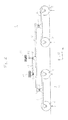
- Such a guide system 18 is in one embodiment in Fig. 5 exemplified.
- This guide system comprises a number of guide elements 1.
- These guide elements can from the Fig. 1 - 4th but may also consist essentially only of a single guide roller 2, which are applied to the conveyor belt 4.
- the guide elements 1 of the guide system according to Fig. 5 are thus not limited to the above embodiments.
- the guide elements 1 after Fig. 5 are specifically arranged opposite each other to allow both sides a safe and accurate web guide.
- a pair of guide elements is arranged directly in front of the printing unit 20 in order to prevent a displacement of the conveyor belt 4 transversely to the running direction x immediately before the printing unit 20 and thus also during the printing process.
- a particularly high quality of the printed product can be achieved.
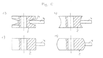
- Fig. 6 Various preferred profiles of the guide rollers 2 are in Fig. 6 shown in cross section.
- a circumferential groove (24) Fig. 6 a
- a concave surface Fig. 6b
- the conveyor belt can be partially enclosed or encompassed by the surface of the guide rollers so that the conveyor belt 4 lies securely in the guide roller 2 and can not jump out.
- a planar Fig. 6 c
- even a convex surface Fig. 6 d
Landscapes
- Engineering & Computer Science (AREA)
- Mechanical Engineering (AREA)
- Feeding Of Articles By Means Other Than Belts Or Rollers (AREA)
- Structure Of Belt Conveyors (AREA)
- Delivering By Means Of Belts And Rollers (AREA)
Applications Claiming Priority (1)
| Application Number | Priority Date | Filing Date | Title |
|---|---|---|---|
| DE102013112827.0A DE102013112827A1 (de) | 2013-11-20 | 2013-11-20 | Führung für ein Transportband in einer Druckmaschine |
Publications (3)
| Publication Number | Publication Date |
|---|---|
| EP2876061A2 true EP2876061A2 (fr) | 2015-05-27 |
| EP2876061A3 EP2876061A3 (fr) | 2015-09-02 |
| EP2876061B1 EP2876061B1 (fr) | 2017-08-02 |
Family
ID=51904747
Family Applications (1)
| Application Number | Title | Priority Date | Filing Date |
|---|---|---|---|
| EP14193003.2A Not-in-force EP2876061B1 (fr) | 2013-11-20 | 2014-11-13 | Guidage pour une bande transporteuse dans une machine à imprimer |
Country Status (3)
| Country | Link |
|---|---|
| EP (1) | EP2876061B1 (fr) |
| CN (1) | CN104647882A (fr) |
| DE (1) | DE102013112827A1 (fr) |
Cited By (1)
| Publication number | Priority date | Publication date | Assignee | Title |
|---|---|---|---|---|
| WO2017098407A1 (fr) * | 2015-12-11 | 2017-06-15 | Uniset S.R.L. | Kit pour surveiller des bandes transporteuses et similaires, et procédé connexe |
Families Citing this family (1)
| Publication number | Priority date | Publication date | Assignee | Title |
|---|---|---|---|---|
| DE102016104768A1 (de) * | 2016-03-15 | 2017-09-21 | Meurer Verpackungssysteme Gmbh | Fördereinrichtung |
Citations (8)
| Publication number | Priority date | Publication date | Assignee | Title |
|---|---|---|---|---|
| US1821664A (en) | 1925-08-29 | 1931-09-01 | Hartford Empire Co | Conveyer guide |
| AT209250B (de) | 1957-12-19 | 1960-05-25 | Zimmer S Erben Kg | Vorrichtung zur Führung von Förderbändern |
| WO1982000975A1 (fr) | 1980-09-12 | 1982-04-01 | Dahlgren H | Transporteuse planetaire |
| DD237643A5 (de) | 1984-10-27 | 1986-07-23 | �����@������������������k�� | Steuervorrichtung zum ausrichten eines um zwei rollen umlaufenden endlosbandes |
| EP0402725A1 (fr) | 1989-06-14 | 1990-12-19 | Bridgestone/Firestone, Inc. | Bande transporteuse et système de guidage pour cela |
| DE4034427A1 (de) | 1989-11-06 | 1991-05-08 | Andritz Ag Maschf | Foerderbandgurt, verfahren und vorrichtung zu seiner herstellung sowie seitenfuehrung fuer einen solchen gurt |
| WO1998022373A1 (fr) | 1996-11-19 | 1998-05-28 | Santrade Ltd. | Dispositif de commande du mouvement rectiligne d'une bande sans fin |
| DE10023689A1 (de) | 2000-05-16 | 2001-12-06 | Roland Man Druckmasch | Kombinierte Druckmaschine |
Family Cites Families (2)
| Publication number | Priority date | Publication date | Assignee | Title |
|---|---|---|---|---|
| DE2723033C2 (de) * | 1977-05-21 | 1979-07-12 | Conrad Scholtz Ag, 2000 Hamburg | Kurvengurtförderer |
| US6494451B2 (en) * | 2001-03-19 | 2002-12-17 | Hewlett-Packard Company | Anti-skew idler roller system |
-
2013
- 2013-11-20 DE DE102013112827.0A patent/DE102013112827A1/de not_active Withdrawn
-
2014
- 2014-11-13 EP EP14193003.2A patent/EP2876061B1/fr not_active Not-in-force
- 2014-11-20 CN CN201410666183.0A patent/CN104647882A/zh active Pending
Patent Citations (8)
| Publication number | Priority date | Publication date | Assignee | Title |
|---|---|---|---|---|
| US1821664A (en) | 1925-08-29 | 1931-09-01 | Hartford Empire Co | Conveyer guide |
| AT209250B (de) | 1957-12-19 | 1960-05-25 | Zimmer S Erben Kg | Vorrichtung zur Führung von Förderbändern |
| WO1982000975A1 (fr) | 1980-09-12 | 1982-04-01 | Dahlgren H | Transporteuse planetaire |
| DD237643A5 (de) | 1984-10-27 | 1986-07-23 | �����@������������������k�� | Steuervorrichtung zum ausrichten eines um zwei rollen umlaufenden endlosbandes |
| EP0402725A1 (fr) | 1989-06-14 | 1990-12-19 | Bridgestone/Firestone, Inc. | Bande transporteuse et système de guidage pour cela |
| DE4034427A1 (de) | 1989-11-06 | 1991-05-08 | Andritz Ag Maschf | Foerderbandgurt, verfahren und vorrichtung zu seiner herstellung sowie seitenfuehrung fuer einen solchen gurt |
| WO1998022373A1 (fr) | 1996-11-19 | 1998-05-28 | Santrade Ltd. | Dispositif de commande du mouvement rectiligne d'une bande sans fin |
| DE10023689A1 (de) | 2000-05-16 | 2001-12-06 | Roland Man Druckmasch | Kombinierte Druckmaschine |
Cited By (1)
| Publication number | Priority date | Publication date | Assignee | Title |
|---|---|---|---|---|
| WO2017098407A1 (fr) * | 2015-12-11 | 2017-06-15 | Uniset S.R.L. | Kit pour surveiller des bandes transporteuses et similaires, et procédé connexe |
Also Published As
| Publication number | Publication date |
|---|---|
| EP2876061B1 (fr) | 2017-08-02 |
| EP2876061A3 (fr) | 2015-09-02 |
| DE102013112827A1 (de) | 2015-05-21 |
| CN104647882A (zh) | 2015-05-27 |
Similar Documents
| Publication | Publication Date | Title |
|---|---|---|
| DE3628282A1 (de) | Stationaere stuetzvorrichtung | |
| DE19960649B4 (de) | Vorrichtung zur Korrektur der lateralen Position einer Bedruckstoffbahn in einer Rollenrotationsdruckmaschine | |
| EP2193548A2 (fr) | Procédé de fabrication d'une cellule solaire | |
| EP2876061B1 (fr) | Guidage pour une bande transporteuse dans une machine à imprimer | |
| EP0220415B1 (fr) | Machine pour couper des plaques | |
| DE4413501A1 (de) | Verfahren und Vorrichtung zur Faserbündelimprägnierung | |
| DE3045939A1 (de) | Traegerstreifen zur maschinellen anbringung an behaeltern | |
| DE4407405C2 (de) | Trockenpartie | |
| EP1074381A1 (fr) | Dispositif de gaufrage | |
| DE102005048246B4 (de) | Rotationsdruckmaschine mit Längendehnungs-Kompensator und Verfahren zum Bedrucken einer längsgeschnittenen Bahn | |
| DE19711271C2 (de) | Längenmeßsystem | |
| AT402746B (de) | Doppelsiebformer mit örtlich verstellbarer entwässerungsleiste | |
| DE202008000890U1 (de) | Bahnspreizeinrichtung für eine Rotationsdruckmaschine und damit ausgerüstete Rotationsdruckmaschine | |
| EP0521966B1 (fr) | Dispositif hydraulique de support | |
| DE10335758C5 (de) | Verfahren und Druckwerk zur Beeinflussung der lateralen Bahnspreizung insbesondere an Rotationsdruckmaschinen | |
| DE102005005302A1 (de) | Druckwerk einer Druckmaschine | |
| DE102016208620A1 (de) | Vorrichtung zum Spreitzen eines Faserbündels, insbesondere eines Carbon-Faserbündels | |
| DE102008005392A1 (de) | Bahnspreizeinrichtung für eine Rotationsdruckmaschine und damit ausgerüstete Rotationsdruckmaschine | |
| DE102007015694A1 (de) | Spinnmaschine | |
| AT399355B (de) | Vorrichtung zur entwässerung von faserstoff-flüssigkeit-mischungen | |
| DE9414450U1 (de) | Deckelkarde mit mindestens einem System umlaufend angetriebener Deckelstäbe | |
| WO2002100749A1 (fr) | Procede et dispositif pour retourner des bandes | |
| DE4402928C2 (de) | Trockenpartie | |
| DE2758721A1 (de) | Reibungsverstaerkende endenausfuehrung fuer blattfedern | |
| EP0714770A1 (fr) | Dispositif pour transporter du papier |
Legal Events
| Date | Code | Title | Description |
|---|---|---|---|
| PUAI | Public reference made under article 153(3) epc to a published international application that has entered the european phase |
Free format text: ORIGINAL CODE: 0009012 |
|
| 17P | Request for examination filed |
Effective date: 20141113 |
|
| AK | Designated contracting states |
Kind code of ref document: A2 Designated state(s): AL AT BE BG CH CY CZ DE DK EE ES FI FR GB GR HR HU IE IS IT LI LT LU LV MC MK MT NL NO PL PT RO RS SE SI SK SM TR |
|
| AX | Request for extension of the european patent |
Extension state: BA ME |
|
| PUAL | Search report despatched |
Free format text: ORIGINAL CODE: 0009013 |
|
| AK | Designated contracting states |
Kind code of ref document: A3 Designated state(s): AL AT BE BG CH CY CZ DE DK EE ES FI FR GB GR HR HU IE IS IT LI LT LU LV MC MK MT NL NO PL PT RO RS SE SI SK SM TR |
|
| AX | Request for extension of the european patent |
Extension state: BA ME |
|
| RIC1 | Information provided on ipc code assigned before grant |
Ipc: B65G 39/16 20060101ALI20150724BHEP Ipc: B65G 15/64 20060101AFI20150724BHEP |
|
| R17P | Request for examination filed (corrected) |
Effective date: 20160302 |
|
| RBV | Designated contracting states (corrected) |
Designated state(s): AL AT BE BG CH CY CZ DE DK EE ES FI FR GB GR HR HU IE IS IT LI LT LU LV MC MK MT NL NO PL PT RO RS SE SI SK SM TR |
|
| 17Q | First examination report despatched |
Effective date: 20160705 |
|
| GRAP | Despatch of communication of intention to grant a patent |
Free format text: ORIGINAL CODE: EPIDOSNIGR1 |
|
| INTG | Intention to grant announced |
Effective date: 20170412 |
|
| GRAS | Grant fee paid |
Free format text: ORIGINAL CODE: EPIDOSNIGR3 |
|
| GRAA | (expected) grant |
Free format text: ORIGINAL CODE: 0009210 |
|
| AK | Designated contracting states |
Kind code of ref document: B1 Designated state(s): AL AT BE BG CH CY CZ DE DK EE ES FI FR GB GR HR HU IE IS IT LI LT LU LV MC MK MT NL NO PL PT RO RS SE SI SK SM TR |
|
| REG | Reference to a national code |
Ref country code: CH Ref legal event code: EP Ref country code: AT Ref legal event code: REF Ref document number: 914196 Country of ref document: AT Kind code of ref document: T Effective date: 20170815 |
|
| REG | Reference to a national code |
Ref country code: IE Ref legal event code: FG4D Free format text: LANGUAGE OF EP DOCUMENT: GERMAN |
|
| REG | Reference to a national code |
Ref country code: DE Ref legal event code: R096 Ref document number: 502014004787 Country of ref document: DE |
|
| REG | Reference to a national code |
Ref country code: NL Ref legal event code: MP Effective date: 20170802 |
|
| REG | Reference to a national code |
Ref country code: LT Ref legal event code: MG4D |
|
| PG25 | Lapsed in a contracting state [announced via postgrant information from national office to epo] |
Ref country code: SE Free format text: LAPSE BECAUSE OF FAILURE TO SUBMIT A TRANSLATION OF THE DESCRIPTION OR TO PAY THE FEE WITHIN THE PRESCRIBED TIME-LIMIT Effective date: 20170802 Ref country code: FI Free format text: LAPSE BECAUSE OF FAILURE TO SUBMIT A TRANSLATION OF THE DESCRIPTION OR TO PAY THE FEE WITHIN THE PRESCRIBED TIME-LIMIT Effective date: 20170802 Ref country code: HR Free format text: LAPSE BECAUSE OF FAILURE TO SUBMIT A TRANSLATION OF THE DESCRIPTION OR TO PAY THE FEE WITHIN THE PRESCRIBED TIME-LIMIT Effective date: 20170802 Ref country code: LT Free format text: LAPSE BECAUSE OF FAILURE TO SUBMIT A TRANSLATION OF THE DESCRIPTION OR TO PAY THE FEE WITHIN THE PRESCRIBED TIME-LIMIT Effective date: 20170802 Ref country code: NO Free format text: LAPSE BECAUSE OF FAILURE TO SUBMIT A TRANSLATION OF THE DESCRIPTION OR TO PAY THE FEE WITHIN THE PRESCRIBED TIME-LIMIT Effective date: 20171102 Ref country code: NL Free format text: LAPSE BECAUSE OF FAILURE TO SUBMIT A TRANSLATION OF THE DESCRIPTION OR TO PAY THE FEE WITHIN THE PRESCRIBED TIME-LIMIT Effective date: 20170802 |
|
| PG25 | Lapsed in a contracting state [announced via postgrant information from national office to epo] |
Ref country code: IS Free format text: LAPSE BECAUSE OF FAILURE TO SUBMIT A TRANSLATION OF THE DESCRIPTION OR TO PAY THE FEE WITHIN THE PRESCRIBED TIME-LIMIT Effective date: 20171202 Ref country code: PL Free format text: LAPSE BECAUSE OF FAILURE TO SUBMIT A TRANSLATION OF THE DESCRIPTION OR TO PAY THE FEE WITHIN THE PRESCRIBED TIME-LIMIT Effective date: 20170802 Ref country code: BG Free format text: LAPSE BECAUSE OF FAILURE TO SUBMIT A TRANSLATION OF THE DESCRIPTION OR TO PAY THE FEE WITHIN THE PRESCRIBED TIME-LIMIT Effective date: 20171102 Ref country code: RS Free format text: LAPSE BECAUSE OF FAILURE TO SUBMIT A TRANSLATION OF THE DESCRIPTION OR TO PAY THE FEE WITHIN THE PRESCRIBED TIME-LIMIT Effective date: 20170802 Ref country code: ES Free format text: LAPSE BECAUSE OF FAILURE TO SUBMIT A TRANSLATION OF THE DESCRIPTION OR TO PAY THE FEE WITHIN THE PRESCRIBED TIME-LIMIT Effective date: 20170802 Ref country code: GR Free format text: LAPSE BECAUSE OF FAILURE TO SUBMIT A TRANSLATION OF THE DESCRIPTION OR TO PAY THE FEE WITHIN THE PRESCRIBED TIME-LIMIT Effective date: 20171103 Ref country code: LV Free format text: LAPSE BECAUSE OF FAILURE TO SUBMIT A TRANSLATION OF THE DESCRIPTION OR TO PAY THE FEE WITHIN THE PRESCRIBED TIME-LIMIT Effective date: 20170802 |
|
| PG25 | Lapsed in a contracting state [announced via postgrant information from national office to epo] |
Ref country code: RO Free format text: LAPSE BECAUSE OF FAILURE TO SUBMIT A TRANSLATION OF THE DESCRIPTION OR TO PAY THE FEE WITHIN THE PRESCRIBED TIME-LIMIT Effective date: 20170802 Ref country code: DK Free format text: LAPSE BECAUSE OF FAILURE TO SUBMIT A TRANSLATION OF THE DESCRIPTION OR TO PAY THE FEE WITHIN THE PRESCRIBED TIME-LIMIT Effective date: 20170802 Ref country code: CZ Free format text: LAPSE BECAUSE OF FAILURE TO SUBMIT A TRANSLATION OF THE DESCRIPTION OR TO PAY THE FEE WITHIN THE PRESCRIBED TIME-LIMIT Effective date: 20170802 |
|
| REG | Reference to a national code |
Ref country code: DE Ref legal event code: R097 Ref document number: 502014004787 Country of ref document: DE |
|
| PG25 | Lapsed in a contracting state [announced via postgrant information from national office to epo] |
Ref country code: IT Free format text: LAPSE BECAUSE OF FAILURE TO SUBMIT A TRANSLATION OF THE DESCRIPTION OR TO PAY THE FEE WITHIN THE PRESCRIBED TIME-LIMIT Effective date: 20170802 Ref country code: SK Free format text: LAPSE BECAUSE OF FAILURE TO SUBMIT A TRANSLATION OF THE DESCRIPTION OR TO PAY THE FEE WITHIN THE PRESCRIBED TIME-LIMIT Effective date: 20170802 Ref country code: SM Free format text: LAPSE BECAUSE OF FAILURE TO SUBMIT A TRANSLATION OF THE DESCRIPTION OR TO PAY THE FEE WITHIN THE PRESCRIBED TIME-LIMIT Effective date: 20170802 Ref country code: EE Free format text: LAPSE BECAUSE OF FAILURE TO SUBMIT A TRANSLATION OF THE DESCRIPTION OR TO PAY THE FEE WITHIN THE PRESCRIBED TIME-LIMIT Effective date: 20170802 |
|
| PLBE | No opposition filed within time limit |
Free format text: ORIGINAL CODE: 0009261 |
|
| STAA | Information on the status of an ep patent application or granted ep patent |
Free format text: STATUS: NO OPPOSITION FILED WITHIN TIME LIMIT |
|
| PG25 | Lapsed in a contracting state [announced via postgrant information from national office to epo] |
Ref country code: MC Free format text: LAPSE BECAUSE OF FAILURE TO SUBMIT A TRANSLATION OF THE DESCRIPTION OR TO PAY THE FEE WITHIN THE PRESCRIBED TIME-LIMIT Effective date: 20170802 |
|
| 26N | No opposition filed |
Effective date: 20180503 |
|
| PG25 | Lapsed in a contracting state [announced via postgrant information from national office to epo] |
Ref country code: CH Free format text: LAPSE BECAUSE OF NON-PAYMENT OF DUE FEES Effective date: 20171130 Ref country code: LI Free format text: LAPSE BECAUSE OF NON-PAYMENT OF DUE FEES Effective date: 20171130 |
|
| PG25 | Lapsed in a contracting state [announced via postgrant information from national office to epo] |
Ref country code: SI Free format text: LAPSE BECAUSE OF FAILURE TO SUBMIT A TRANSLATION OF THE DESCRIPTION OR TO PAY THE FEE WITHIN THE PRESCRIBED TIME-LIMIT Effective date: 20170802 Ref country code: LU Free format text: LAPSE BECAUSE OF NON-PAYMENT OF DUE FEES Effective date: 20171113 |
|
| REG | Reference to a national code |
Ref country code: FR Ref legal event code: ST Effective date: 20180731 Ref country code: BE Ref legal event code: MM Effective date: 20171130 |
|
| REG | Reference to a national code |
Ref country code: IE Ref legal event code: MM4A |
|
| PG25 | Lapsed in a contracting state [announced via postgrant information from national office to epo] |
Ref country code: MT Free format text: LAPSE BECAUSE OF FAILURE TO SUBMIT A TRANSLATION OF THE DESCRIPTION OR TO PAY THE FEE WITHIN THE PRESCRIBED TIME-LIMIT Effective date: 20170802 |
|
| PG25 | Lapsed in a contracting state [announced via postgrant information from national office to epo] |
Ref country code: FR Free format text: LAPSE BECAUSE OF NON-PAYMENT OF DUE FEES Effective date: 20171130 Ref country code: IE Free format text: LAPSE BECAUSE OF NON-PAYMENT OF DUE FEES Effective date: 20171113 |
|
| REG | Reference to a national code |
Ref country code: DE Ref legal event code: R081 Ref document number: 502014004787 Country of ref document: DE Owner name: MANROLAND GOSS WEB SYSTEMS GMBH, DE Free format text: FORMER OWNER: MANROLAND WEB SYSTEMS GMBH, 86153 AUGSBURG, DE |
|
| PG25 | Lapsed in a contracting state [announced via postgrant information from national office to epo] |
Ref country code: BE Free format text: LAPSE BECAUSE OF NON-PAYMENT OF DUE FEES Effective date: 20171130 |
|
| PGFP | Annual fee paid to national office [announced via postgrant information from national office to epo] |
Ref country code: DE Payment date: 20181120 Year of fee payment: 5 |
|
| PG25 | Lapsed in a contracting state [announced via postgrant information from national office to epo] |
Ref country code: HU Free format text: LAPSE BECAUSE OF FAILURE TO SUBMIT A TRANSLATION OF THE DESCRIPTION OR TO PAY THE FEE WITHIN THE PRESCRIBED TIME-LIMIT; INVALID AB INITIO Effective date: 20141113 |
|
| GBPC | Gb: european patent ceased through non-payment of renewal fee |
Effective date: 20181113 |
|
| PG25 | Lapsed in a contracting state [announced via postgrant information from national office to epo] |
Ref country code: CY Free format text: LAPSE BECAUSE OF FAILURE TO SUBMIT A TRANSLATION OF THE DESCRIPTION OR TO PAY THE FEE WITHIN THE PRESCRIBED TIME-LIMIT Effective date: 20170802 |
|
| PG25 | Lapsed in a contracting state [announced via postgrant information from national office to epo] |
Ref country code: MK Free format text: LAPSE BECAUSE OF FAILURE TO SUBMIT A TRANSLATION OF THE DESCRIPTION OR TO PAY THE FEE WITHIN THE PRESCRIBED TIME-LIMIT Effective date: 20170802 |
|
| PG25 | Lapsed in a contracting state [announced via postgrant information from national office to epo] |
Ref country code: GB Free format text: LAPSE BECAUSE OF NON-PAYMENT OF DUE FEES Effective date: 20181113 |
|
| PG25 | Lapsed in a contracting state [announced via postgrant information from national office to epo] |
Ref country code: TR Free format text: LAPSE BECAUSE OF FAILURE TO SUBMIT A TRANSLATION OF THE DESCRIPTION OR TO PAY THE FEE WITHIN THE PRESCRIBED TIME-LIMIT Effective date: 20170802 |
|
| PG25 | Lapsed in a contracting state [announced via postgrant information from national office to epo] |
Ref country code: PT Free format text: LAPSE BECAUSE OF FAILURE TO SUBMIT A TRANSLATION OF THE DESCRIPTION OR TO PAY THE FEE WITHIN THE PRESCRIBED TIME-LIMIT Effective date: 20170802 |
|
| REG | Reference to a national code |
Ref country code: DE Ref legal event code: R119 Ref document number: 502014004787 Country of ref document: DE |
|
| PG25 | Lapsed in a contracting state [announced via postgrant information from national office to epo] |
Ref country code: AL Free format text: LAPSE BECAUSE OF FAILURE TO SUBMIT A TRANSLATION OF THE DESCRIPTION OR TO PAY THE FEE WITHIN THE PRESCRIBED TIME-LIMIT Effective date: 20170802 |
|
| PG25 | Lapsed in a contracting state [announced via postgrant information from national office to epo] |
Ref country code: DE Free format text: LAPSE BECAUSE OF NON-PAYMENT OF DUE FEES Effective date: 20200603 |
|
| REG | Reference to a national code |
Ref country code: AT Ref legal event code: MM01 Ref document number: 914196 Country of ref document: AT Kind code of ref document: T Effective date: 20191113 |
|
| PG25 | Lapsed in a contracting state [announced via postgrant information from national office to epo] |
Ref country code: AT Free format text: LAPSE BECAUSE OF NON-PAYMENT OF DUE FEES Effective date: 20191113 |