EP2874256A2 - Muffe mit Informationselement - Google Patents
Muffe mit Informationselement Download PDFInfo
- Publication number
- EP2874256A2 EP2874256A2 EP20140161678 EP14161678A EP2874256A2 EP 2874256 A2 EP2874256 A2 EP 2874256A2 EP 20140161678 EP20140161678 EP 20140161678 EP 14161678 A EP14161678 A EP 14161678A EP 2874256 A2 EP2874256 A2 EP 2874256A2
- Authority
- EP
- European Patent Office
- Prior art keywords
- sealing element
- housing
- sleeve
- cable
- projection
- Prior art date
- Legal status (The legal status is an assumption and is not a legal conclusion. Google has not performed a legal analysis and makes no representation as to the accuracy of the status listed.)
- Granted
Links
Images


Classifications
-
- H—ELECTRICITY
- H02—GENERATION; CONVERSION OR DISTRIBUTION OF ELECTRIC POWER
- H02G—INSTALLATION OF ELECTRIC CABLES OR LINES, OR OF COMBINED OPTICAL AND ELECTRIC CABLES OR LINES
- H02G15/00—Cable fittings
- H02G15/08—Cable junctions
- H02G15/10—Cable junctions protected by boxes, e.g. by distribution, connection or junction boxes
- H02G15/113—Boxes split longitudinally in main cable direction
-
- H—ELECTRICITY
- H02—GENERATION; CONVERSION OR DISTRIBUTION OF ELECTRIC POWER
- H02G—INSTALLATION OF ELECTRIC CABLES OR LINES, OR OF COMBINED OPTICAL AND ELECTRIC CABLES OR LINES
- H02G15/00—Cable fittings
- H02G15/013—Sealing means for cable inlets
-
- H—ELECTRICITY
- H02—GENERATION; CONVERSION OR DISTRIBUTION OF ELECTRIC POWER
- H02G—INSTALLATION OF ELECTRIC CABLES OR LINES, OR OF COMBINED OPTICAL AND ELECTRIC CABLES OR LINES
- H02G3/00—Installations of electric cables or lines or protective tubing therefor in or on buildings, equivalent structures or vehicles
- H02G3/02—Details
- H02G3/06—Joints for connecting lengths of protective tubing or channels, to each other or to casings, e.g. to distribution boxes; Ensuring electrical continuity in the joint
-
- H—ELECTRICITY
- H02—GENERATION; CONVERSION OR DISTRIBUTION OF ELECTRIC POWER
- H02G—INSTALLATION OF ELECTRIC CABLES OR LINES, OR OF COMBINED OPTICAL AND ELECTRIC CABLES OR LINES
- H02G9/00—Installations of electric cables or lines in or on the ground or water
- H02G9/06—Installations of electric cables or lines in or on the ground or water in underground tubes or conduits; Tubes or conduits therefor
- H02G9/065—Longitudinally split tubes or conduits therefor
Definitions
- the present invention relates to a sleeve with an information element.
- the present invention also relates to a cable assembly and a cable tube assembly with such a sleeve.
- Sleeves are used in microcable technology to connect such microcable tubes together. High demands are placed on such sleeves as regards gas and / or water tightness and tensile strength. In particular, they are also required to make house connections in order to lay a cable in a house, for example.
- the seal between the tubes is not tapered and has a correspondingly large cross-section, but corresponds to the inner diameter of the tubes.
- a gas transfer between the pipes is possible and the cable can be pulled out or blown out.
- the sealing element is designed as an insertion seal in the form of a tube made of flexible material.
- the sealing element is shaped such that it is aufbiegbar to receive in the bent state, the cable and / or the or the cable ducts.
- the sealing element for example along its axis have an incision along which the unfolding is accomplished.
- the flexible material of the sealing element causes a "collapse" as soon as the applied force for bending no longer rests.
- the sealing element is preferably symmetrically shaped, in particular, the sealing element is formed approximately in the form of a hollow cylinder.
- the sealing element has two ends, which are arranged symmetrically to each other with respect to a mirror plane through the center of the sealing element and perpendicular to the axis of the hollow cylinder.
- the two ends of the cable tube can be inserted in the end in a simple manner, wherein the flexible material is then compressed after arranging the housing and closing the housing and securely seals the pipes to be joined.
- the opening in at least one part of the housing and the information element are arranged one behind the other on the sealing element, so that the information element can be identified from the outside of the housing.
- the successive arrangement of the information element on the sealing element and the opening on the housing makes it possible to obtain from the outside of the housing information about which type of sealing element is installed in the sleeve.
- the information is easily accessible in this way.
- the information element on the sealing element can very favorably be a color marking and / or a surface structure and / or a projection and / or a depression.
- an information element on the sealing element in the form of a color marking and / or a surface structure and / or a projection and / or a recess, it is possible in a simple manner to provide information of what kind is the sealing element installed in the sleeve.
- a color marking is very advantageous as an information element, because it has an easy recognizability, attracted attention and ensures a high degree of distinctiveness.
- Preferred colors in this context are red, orange and yellow.
- the color of the sealing element is very advantageous to select different from the color of the housing, so as to achieve a high color contrast.
- a surface structure is particularly favorable to use as an information element, since this has an easy recognizability and / or tactility and thus conveys the information both on the visual sense, as well as the haptic sense.
- Suitable surface structures relate to smooth surfaces or rough surfaces and various surface structures, such as knobs, lines or grids.
- a projection as an information element has a particularly good recognizability.
- the information element is formed in the form of a projection which penetrates through the opening in at least a part of the housing.
- the projection is then to be recognized or palpated on the outside of the housing as over the surface raised portion.
- An information element in the form of a projection on the sealing element, which penetrates through the opening in at least a part of the housing, makes it possible in a simple manner to obtain information both by a visual inspection and by a tactile control, of what kind in the Muff is built-in sealing element.
- a further advantage is associated with the information element in the form of a projection on the sealing element.
- the projection is integrally formed with the sealing element.
- Such integral formation of the projection with the sealing element is very easily possible in the production of the sealing element, for example in a pressing process or an injection molding process. As a result, costs can be reduced, the reproducibility of such a manufacturing technique is also very high. Furthermore, thereby the projection is arranged captive on the sealing element.
- the projection is formed approximately centrally on the sealing element radially projecting.
- a projection which is formed approximately centrally projecting radially on the sealing element can be used without an orientation to be observed in the housing.
- the projection projecting approximately centrally on the sealing element causes a secure position in the housing, without the sealing element being able to be displaced.
- the projection on the sealing element is cylindrical or cuboidal or conical or rod-shaped or pointed or designed as an ellipsoid or in a mixed form of the aforementioned forms.
- a projection on the sealing element in one of the aforementioned forms is particularly well suited to provide both the information about the nature of the sealing element by visual or tactile control available, as well as safely oriented in the housing and arranged to be defined.
- the sealing element which has a tapered cross-section
- an information element which is uniquely distinguishable from a sealing element, which has no cross-sectional taper and has a different information element.
- sealing element which has a tapered cross-section
- a projection is provided with a projection.
- the sealing element which does not have a tapered cross-section, is provided with a projection.
- the housing itself is composed of housing parts.
- two, three or more housing parts may be provided which receive the sealing element in the assembled state.
- a housing of three housing parts is preferred.
- the object of the invention to provide a cable assembly and a cable tube assembly with a sleeve learns their solution in claim 10. It has been recognized in the invention that a cable assembly or a cable tube assembly with at least one sleeve of the aforementioned type can be used advantageously in a very special way to connect cables or conduits together to provide a cable assembly or cable conduit assembly.
- Fig. 1 the plan view of a sleeve 20 according to the invention is shown.
- the sleeve 20 comprises a housing 28 of three housing parts 22, which is connected by means of a connecting element 23.
- the connecting element 23 cooperates with the housing parts 22 of the housing 28 by a wedge-shaped connection arrangement, not shown here.
- a sealing element 21 is arranged inside the sleeve 20 inside the sleeve 20. From the sealing element 21 are approximately centrally arranged two projections 26 radially approximately opposite each other out. The projections 26 penetrate through openings 24 in the housing 28 to the outside.
- sealing element 21 On the sealing element 21 four retaining elements 27 are further formed, which penetrate into corresponding openings on the housing 28. At the two end faces of the sleeve 20 are - without which it is shown here - to introduce cables or conduits in the sleeve 20.
- FIG. 2 a cross-sectional view of the sleeve 20 according to the invention is shown.
- a sealing element 21 is added thereto.
- the sealing element 21 has approximately radially opposite projections 26 approximately opposite each other and arranged approximately centrally.
- Fig. 2 For this purpose, only one projection 26 is shown, the second projection 26 has been omitted for clarity.
- the aperture 24 between two housing parts 22 of the housing 28 is shown, through which the projection 26 penetrates.
- the projection 26 has approximately the shape of a truncated cone.
- the opening 24 between two housing parts 22 of the housing 28 is approximately circular.
- the holding elements 27 have an approximately double truncated cone-like shape, so that these holding elements 27 have an incision approximately halfway up.
- the holding elements 27 are integrally formed on the sealing element 21.
- the holding elements 27 penetrate into corresponding apertures on the housing 28 and are clamped by the edges of the openings at the incisions. In this way, the holding elements 27 ensure the defined and secure position of the sealing element 21 in the housing 28.
- the sealing element 21 shown in FIG Fig. 2 has approximately centrally a cross-sectional taper. By arranged on both sides of the cross-sectional taper larger inner diameter of the sealing element 21 can then be inserted, for example, not shown here cable tube ends to connect them. Due to the tapered diameter approximately in the middle of the sealing element 21, the cable received in the cable ducts can be passed. The implementation is then carried out in a gas-tight design, so that no gas can pass from one cable to the other cable.
- the sealing element is also defined and securely positioned within the housing 28 of the sleeve 20.
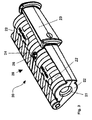
- FIG. 3 is a perspective side view of the sleeve 20 of the invention shown.
- the sleeve 20 comprises a housing 28 made of three housing parts 22, in which the three housing parts 22 of the housing 28 are connected to one another in an articulated manner. Inside the housing 28, the sealing element 21 is received.
- the three housing parts 22 of the housing 28 can be connected by connecting elements 23 - of which only one is shown - by a wedge-shaped connection technology.
- an approximately circular opening 24 is approximately centrally disposed, wherein at this point two housing parts 22 of the housing 28 abut one another.
- the projection 26 of the sealing element 21 can be detected both by visual contact, as well as by tactile contact and thus provides information about the arranged in the housing 28 sealing element 21 and in particular its cross-sectional design available.
- the housing 28 may also be formed in two parts or in several parts.
- the individual housing parts 22 of the housing 28 can - without being articulated to each other - also be connected differently.
- Connecting elements for connecting these individual housing parts 22 of the housing 28 may be of a variety of nature, with wedge-shaped connection techniques being preferred on account of their simplicity and in particular simple operability.
- Fig. 4 is a detail of the sleeve 20 off Fig. 2 shown in a cross-sectional view.
- both projections 26 as well as holding elements 27 are integrally formed.
- the projections 26 are formed approximately centrally on the sealing element 21, thereby formed approximately diametrically opposite and radially projecting.
- the projections 26 are formed approximately as truncated cones. Furthermore, a plurality of holding elements 27 are integrally formed on the sealing element 21. The holding elements 27 are arranged in a preferred embodiment of the invention only on one side of the sealing element 21.
- the holding elements 27 are shaped like a double truncated cone and have an incision about halfway up.
- Fig. 5 a top view of a detail of the sealing element 21 is shown.
- the holding elements 27 are shown in detail.
Landscapes
- Engineering & Computer Science (AREA)
- Architecture (AREA)
- Civil Engineering (AREA)
- Structural Engineering (AREA)
- Connector Housings Or Holding Contact Members (AREA)
- Installation Of Indoor Wiring (AREA)
- Laying Of Electric Cables Or Lines Outside (AREA)
- Cable Accessories (AREA)
Abstract
Description
- Die vorliegende Erfindung betrifft eine Muffe mit einem Informationselement. Daneben betrifft die vorliegende Erfindung auch eine Kabelanordnung und eine Kabelrohranordnung mit einer solchen Muffe.
- Muffen werden in der Mikrokabelrohrtechnik eingesetzt, um solche Mikrokabelrohre miteinander zu verbinden. An solche Muffen werden hohe Anforderungen gestellt, was die Gas- und / oder Wasserdichtigkeit und die Zugfestigkeit betrifft. Sie werden insbesondere auch dazu benötigt, Hausanschlüsse herzustellen, um damit beispielsweise ein Kabel in ein Haus zu legen.
- Bei solchen Muffen wird unterschieden zwischen solchen, deren Dichtung zwischen den Rohren sich auf den Kabeldurchmesser verjüngt und einen entsprechend kleinen Querschnitt aufweist, so dass zwischen den Rohren kein Gasübertritt möglich ist. Das Kabel kann ohne Öffnen dieser Muffe nicht mehr entfernt werden.
- In einer zweiten Ausführungsart ist die Dichtung zwischen den Rohren nicht verjüngt und weist einen entsprechend großen Querschnitt auf, sondern entspricht dem Innendurchmesser der Rohre. Bei dieser Variante ist ein Gasübertritt zwischen den Rohren möglich und das Kabel kann ausgezogen bzw. ausgeblasen werden.
- Der Muffe selbst ist nicht anzusehen, welche Art von Dichtung eingebaut ist.
- Es besteht daher die Notwendigkeit, die Ausführungsvariante im Einbauzustand schnell und sicher erkennen zu können.
- Hier setzt die Erfindung ein, die sich die Aufgabe gestellt hat, eine Muffe zur Verfügung zu stellen, die mit technisch einfachen Mitteln die Information bereitstellt, welche Art von Dichtung in ihr verbaut ist.
- Erfindungsgemäß wird dies durch die im kennzeichnenden Teil des Anspruchs 1 angegebenen Merkmale gelöst.
- Weitere vorteilhafte Ausgestaltungen der Erfindung sind in den Unteransprüchen angegeben.
- Es wurde erkannt, dass eine Muffe mit einem Dichtelement zum Umschließen eines Kabels oder Kabelrohres und einem das Dichtelement zumindest teilweise umgebenden mehrteiligen Gehäuse mit einem Innenquerschnitt quer zum Kabel oder Kabelrohr, welcher kleiner ist als der Querschnitt des Dichtelements quer zum Kabel oder Kabelrohr, wobei das Gehäuse von einem Verbindungselement zusammengehalten ist, dann ganz besonders geeignet ist, wenn wenigstens ein Teil des Gehäuses einen Durchbruch aufweist und an dem Dichtelement ein Informationselement angeordnet ist.
- Durch das Vorsehen eines Informationselements an dem Dichtelement in Kombination mit einem Durchbruch in wenigstens einem Teil des Gehäuses kann eine Information wiedergegeben werden, welche Art von Dichtelement in der Muffe verbaut ist.
- Hierdurch lässt sich unterscheiden, ob ein Dichtelement mit einem verjüngten Querschnitt oder ein Dichtelement ohne einen solchen verjüngten Querschnitt vorliegt.
- Es hat sich im Rahmen der Erfindung als sehr hilfreich erwiesen, wenn das Dichtelement als Einlegedichtung in Form eines Rohres aus flexiblem Material ausgebildet ist. Bevorzugt ist das Dichtelement derart geformt, dass es aufbiegbar ist, um im aufgebogenen Zustand das Kabel und / oder das oder die Kabelrohre aufzunehmen. Hierzu kann das Dichtelement beispielsweise längs seiner Achse einen Einschnitt aufweisen, entlang dessen das Aufklappen bewerkstelligbar ist. Das flexible Material des Dichtelements bewirkt ein "Zuklappen", sobald die angelegte Kraft zum Aufbiegen nicht mehr anliegt.
Das Dichtelement ist bevorzugt symmetrisch geformt, ganz besonders ist das Dichtelement etwa in Form eines Hohlzylinders ausgebildet. Das Dichtelement weist zwei Enden auf, die bezogen auf eine Spiegelebene durch die Mitte des Dichtelements und senkrecht zur Achse des Hohlzylinders symmetrisch zueinander angeordnet sind. - In ein solches Rohr aus flexiblem Material lassen sich endseitig die beiden Enden des Kabelrohres auch in einfacher Weise einschieben, wobei das flexible Material dann nach Anordnen des Gehäuses und Verschließen des Gehäuses komprimiert wird und die zu verbindenden Rohre sicher abdichtet.
- Als sehr vorteilhaft hat sich im Rahmen der vorliegenden Erfindung herausgestellt, wenn der Durchbruch in wenigstens einem Teil des Gehäuses und das Informationselement an dem Dichtelement hintereinanderliegend angeordnet sind, so dass das Informationselement von der Außenseite des Gehäuses aus identifizierbar ist.
- Das hintereinanderliegende Anordnen des Informationselements an dem Dichtelement und des Durchbruchs am Gehäuse gestattet es, von der Außenseite des Gehäuses aus eine Information zu erhalten, welche Art von Dichtelement in der Muffe eingebaut ist. Die Information ist auf diese Weise sehr einfach zugänglich.
- Das Informationselement an dem Dichtelement kann im Rahmen der vorliegenden Erfindung in sehr günstiger Weise eine Farbmarkierung und / oder ein Oberflächenstruktur und / oder ein Vorsprung und / oder eine Vertiefung sein.
- Durch das Vorsehen eines Informationselements an dem Dichtelement in Form einer Farbmarkierung und / oder einer Oberflächenstruktur und / oder eines Vorsprungs und / oder einer Vertiefung ist es in einfacher Weise möglich, eine Information abzugeben, von welcher Art das in der Muffe verbaute Dichtelement ist.
- Eine Farbmarkierung eignet sich sehr vorteilhaft als Informationselement, weil diese eine leichte Erkennbarkeit aufweist, dazu Aufmerksamkeit erregt und in hohem Grade eine Unverwechselbarkeit gewährleistet. Bevorzugte Farben sind in diesem Zusammenhang rot, orange und gelb. Die Farbe des Dichtelements ist sehr vorteilhaft unterschiedlich zur Farbe des Gehäuses auszuwählen, um so einen hohen Farbkontrast zu erzielen.
- Eine Oberflächenstruktur ist besonders günstig als Informationselement zu nutzen, da diese eine leichte Erkenn- und / oder Ertastbarkeit aufweist und so die Information sowohl über den optischen Sinn, wie auch über den haptischen Sinn vermittelt. Geeignete Oberflächenstrukturen betreffen glatte Oberflächen bzw. rauhe Oberflächen und verschiedene Oberflächenstrukturen, wie beispielsweise Noppen, Linien oder Gitter.
- Ein Vorsprung als Informationselement weist eine besonders gute Erkennbarkeit auf.
- In einer besonders bevorzugten Ausführungsart der vorliegenden Erfindung ist vorgesehen, dass an dem Dichtelement das Informationselement in Form eines Vorsprungs ausgebildet ist, der durch den Durchbruch in wenigstens einem Teil des Gehäuses hindurchdringt. Der Vorsprung ist dann an der der Außenseite des Gehäuses als über der Oberfläche erhabener Abschnitt zu erkennen bzw. zu ertasten.
- Ein Informationselement in Form eines Vorsprungs an dem Dichtelement, der durch den Durchbruch in wenigstens einem Teil des Gehäuses hindurchdringt, gestattet es in einfacher Weise, sowohl durch eine Sichtkontrolle, wie auch durch eine Tastkontrolle eine Information darüber zu erhalten, von welcher Art das in der Muffe verbaute Dichtelement ist.
- Gerade unter beengten Platzverhältnissen bzw. mangelnder Beleuchtung in Schächten, Kellern oder Baustellen ist dies von einem großen Vorteil, durch eine Sicht- bzw. Tastkontrolle Informationen zu erhalten, von welcher Art das verbaute Dichtelement ist.
Gerade die dadurch ermöglichte Ertastbarkeit in der Dunkelheit bzw. bei mangelhaften Licht- und / oder Platzverhältnissen oder bei Verschmutzungen ist für das Personal, was an der Muffe Arbeiten auszuführen hat, von sehr großem Vorteil. - Darüber hinaus ist mit dem Informationselement in Form eines Vorsprungs an dem Dichtelement ein weiterer Vorteil verbunden.
Durch den Vorsprung wird eine Lagesicherung des Dichtelements im Gehäuse bewirkt, so dass dieses sich nicht unerwünscht verlagern kann. Das Dichtelement nimmt dadurch im Gehäuse eine definierte Position ein, die durch den Vorsprung fixiert ist. - In einer besonders bevorzugten Ausführungsart der vorliegenden Erfindung ist der Vorsprung mit dem Dichtelement einstückig ausgebildet.
- Ein solches einstückiges Ausbilden des Vorsprungs mit dem Dichtelement ist bei der Herstellung des Dichtelements beispielsweise in einem Pressprozess oder einem Spritzgussprozess sehr einfach möglich. Hierdurch können Kosten reduziert werden, die Reproduzierbarkeit einer solchen Herstelltechnik ist außerdem sehr hoch. Weiterhin ist dadurch der Vorsprung unverlierbar an dem Dichtelement angeordnet.
- Als ganz besonders günstig hat sich bei der vorliegenden Erfindung herausgestellt, wenn der Vorsprung etwa mittig an dem Dichtelement radial abstehenden ausgebildet ist. Durch einen Vorsprung, der etwa mittig an dem Dichtelement radial abstehend ausgebildet ist, kann ein solches Dichtelement ohne eine zu beachtende Orientierung in das Gehäuse eingesetzt werden. Weiterhin bewirkt der etwa mittig an dem Dichtelement radial abstehende Vorsprung eine sichere Lage im Gehäuse, ohne dass sich das Dichtelement verschieben lässt.
- In einer ganz besonders günstigen Ausbildung der vorliegenden Erfindung ist vorgesehen, dass der Vorsprung an dem Dichtelement zylinderförmig oder quaderförmig oder kegelförmig oder stabförmig oder spitz zulaufend oder als Ellipsoid oder in einer Mischform der vorgenannten Formen ausgebildet ist.
- Ein Vorsprung an dem Dichtelement in einer der vorgenannten Formen eignet sich ganz besonders gut, sowohl die Information über die Art des Dichtelements durch Sicht- bzw. Tastkontrolle zur Verfügung zu stellen, wie auch im Gehäuse sicher orientiert und definiert angeordnet zu sein.
- In einer ganz besonders bevorzugten Ausbildung der vorliegenden Erfindung ist vorgesehen, dass zwei einander etwa gegenüberliegende Vorsprünge an dem Dichtelement und zwei zu diesen korrespondierende Durchbrüche am Gehäuse ausgebildet sind.
- Durch diese Maßnahme ist sichergestellt, dass an der Muffe an zwei etwa gegenüberliegenden Orten die Information über das eingebaute Dichtelement dargestellt wird. Hierdurch wird es besonders einfach, die Information über die Art des verbauten Dichtelements zu gewinnen, da dies ohne großen Aufwand bei einer fast beliebigen Orientierung der Muffe erfolgen kann.
- In einer bevorzugten Ausführungsart der vorliegenden Erfindung ist vorgesehen, dass das Dichtelement, welches einen verjüngten Querschnitt aufweist, mit einem Informationselement versehen ist, das eindeutig unterscheidbar ist von einem Dichtelement, das keine Querschnittsverjüngung aufweist und ein anderes Informationselement aufweist.
- Ganz besonders bevorzugt ist in diesem Zusammenhang eine Ausführungsart, bei der das Dichtelement, welches einen verjüngten Querschnitt aufweist, mit einem Vorsprung versehen ist.
Damit ist eine eindeutige Zuordnung - sowohl durch Sicht-, wie auch durch Tastkontrolle - möglich, um die Art des Dichtelements eindeutig festzustellen. - Natürlich kann auch vorgesehen sein, dass das Dichtelement, welches keinen verjüngten Querschnitt aufweist, mit einem Vorsprung versehen ist.
- Letztlich ist das mit den Arbeiten an der Muffe betraute Personal über die Art des Dichtelements und das dieses kennzeichnende Informationselement zu informieren.
- Das Gehäuse selbst ist aus Gehäuseteilen zusammengesetzt. Dazu können zwei, drei oder mehr Gehäuseteile vorgesehen sein, die im zusammengesetzten Zustand das Dichtelement aufnehmen. Bevorzugt ist ein Gehäuse aus drei Gehäuseteilen.
- Die Aufgabe der Erfindung, eine Kabelanordnung und eine Kabelrohranordnung mit einer Muffe anzugeben, erfährt ihre Lösung in Anspruch 10. Es wurde im Rahmen der Erfindung erkannt, dass eine Kabelanordnung oder eine Kabelrohranordnung mit wenigstens einer Muffe der vorgenannten Art in ganz besonderer Weise vorteilhaft einsetzbar ist, um Kabel oder Kabelrohre miteinander zu verbinden und damit eine Kabelanordnung oder eine Kabelrohranordnung zur Verfügung zu stellen.
- Weitere wichtige Merkmale und Vorteile der Erfindung ergeben sich aus den Unteransprüchen, aus den Fig. und aus der zugehörigen Figurenbeschreibung.
- Es versteht sich, dass die vorstehend genannten und die nachstehend noch zu erläuternden Merkmale nicht nur in der jeweils angegebenen Kombination, sondern auch in anderen Kombinationen oder in Alleinstellung verwendbar sind, ohne den Rahmen der vorliegenden Erfindung zu verlassen.
- Bevorzugte Ausführungsbeispiele der Erfindung sind in den Fig. dargestellt und werden in der nachfolgenden Beschreibung näher erläutert, wobei sich gleiche Bezugszeichen auf gleiche oder funktional gleiche oder ähnliche Bauteile beziehen.
- Hierzu zeigen:
- Fig. 1
- eine Aufsicht auf eine erfindungsgemäße Muffe;
- Fig. 2
- eine Querschnittsansicht einer erfindungsgemäßen Muffe;
- Fig. 3
- eine perspektivische seitliche Ansicht einer Muffe gemäß vorliegender Erfindung;
- Fig. 4
- eine Querschnittsansicht eines Details einer Muffe aus
Fig. 2 und - Fig. 5
- eine Aufsicht auf das Dichtelement einer erfindungsgemäßen Muffe.
- In
Fig. 1 ist die Aufsicht auf eine erfindungsgemäße Muffe 20 gezeigt. - Die Muffe 20 umfasst ein Gehäuse 28 aus drei Gehäuseteilen 22, das mithilfe eines Verbindungselements 23 verbunden ist. Das Verbindungselement 23 wirkt mit den Gehäuseteilen 22 des Gehäuses 28 durch eine hier nicht gezeigte keilförmige Verbindungsanordnung zusammen.
- Im Inneren der Muffe 20 ist ein Dichtelement 21 angeordnet. Vom Dichtelement 21 stehen etwa mittig angeordnet zwei Vorsprünge 26 radial etwa einander gegenüberliegend hervor. Die Vorsprünge 26 dringen durch Durchbrüche 24 im Gehäuse 28 nach außen.
- Am Dichtelement 21 sind weiterhin vier Halteelemente 27 angeformt, die in entsprechende Durchbrüche am Gehäuse 28 hindurchdringen. An den beiden Stirnseiten der Muffe 20 sind - ohne das es hier gezeigt ist - Kabel oder Kabelrohre in die Muffe 20 einzuführen.
- In
Fig. 2 ist eine Querschnittsansicht der erfindungsgemäßen Muffe 20 gezeigt. - In einem Gehäuse 28 aus drei Gehäuseteilen 22 ist dazu ein Dichtelement 21 aufgenommen. Das Dichtelement 21 weist einander etwa gegenüberliegend und etwa mittig angeordnet zwei radial hervorstehende Vorsprünge 26 auf. In
Fig. 2 ist dazu nur ein Vorsprung 26 gezeigt, der zweite Vorsprung 26 ist der Übersichtlichkeit halber weggelassen worden. An dieser Stelle ist der Durchbruch 24 zwischen zwei Gehäuseteilen 22 des Gehäuses 28 gezeigt, durch den der Vorsprung 26 hindurchdringt. Der Vorsprung 26 weist etwa die Form eines Kegelstumpfs auf. Der Durchbruch 24 zwischen zwei Gehäuseteilen 22 des Gehäuses 28 ist etwa kreisförmig ausgebildet. - Am Dichtelement 21 sind weiterhin vier Halteelemente 27 angeordnet. Die Halteelemente 27 weisen eine etwa doppelkegelstumpfartige Form auf, so dass diese Halteelemente 27 etwa auf halber Höhe einen Einschnitt aufweisen.
- Die Halteelemente 27 sind einstückig am Dichtelement 21 angeformt.
Die Halteelemente 27 dringen in korrespondierende Durchbrüche am Gehäuse 28 ein und werden von den Rändern der Durchbrüche an den Einschnitten klemmend fixiert. Auf diese Weise gewährleisten die Halteelemente 27 die definierte und sichere Lage des Dichtelements 21 im Gehäuse 28. - Das gezeigte Dichtelement 21 in
Fig. 2 weist etwa mittig eine Querschnittsverjüngung auf. Durch den beiderseits der Querschnittsverjüngung angeordneten größeren Innendurchmesser des Dichtelements 21 lassen sich dann beispielsweise hier nicht gezeigte Kabelrohrenden einführen, um diese zu verbinden. Durch den verjüngten Durchmesser etwa in der Mitte des Dichtelements 21 kann das in den Kabelrohren aufgenommene Kabel hindurchgeführt werden. Die Durchführung erfolgt dann in einer gasdichten Ausführung, so dass kein Gasübertritt von einem Kabelrohr zum anderen Kabelrohr erfolgen kann. - Durch die Vorsprünge 26 am Dichtelement 21 ist das Dichtelement ebenfalls definiert und sicher innerhalb des Gehäuses 28 der Muffe 20 positioniert.
- In
Fig. 3 ist eine perspektivische seitliche Ansicht der erfindungsgemäßen Muffe 20 gezeigt. - Die Muffe 20 umfasst hierzu ein Gehäuse 28 aus drei Gehäuseteilen 22, bei dem die drei Gehäuseteile 22 des Gehäuses 28 gelenkig miteinander verbunden sind. Im Inneren des Gehäuses 28 ist das Dichtelement 21 aufgenommen. Die drei Gehäuseteile 22 des Gehäuses 28 lassen sich mit Verbindungselementen 23 - von denen nur eines gezeigt ist - durch eine keilförmige Verbindungstechnik miteinander verbinden.
- An der Oberseite des Gehäuses 28 ist etwa mittig ein etwa kreisförmiger Durchbruch 24 angeordnet, wobei an dieser Stelle zwei Gehäuseteile 22 des Gehäuses 28 aneinanderstoßen. Durch den Durchbruch 24 an der Oberseite des Gehäuses 28 der Muffe 20 ragt ein etwa kegelstumpfförmig geformter Vorsprung 26 des Dichtelements 21 hindurch und steht ein Stück weit über der Außenoberfläche der Oberseite des Gehäuses 28 hervor. Der Vorsprung 26 des Dichtelements 21 kann sowohl durch Sichtkontakt, wie auch durch Tastkontakt erfasst werden und stellt so eine Information über das im Gehäuse 28 angeordnete Dichtelement 21 und insbesondere dessen Querschnittsausführung zur Verfügung.
- In einer anderen hier nicht gezeigten Ausführungsform kann das Gehäuse 28 auch zweiteilig oder mehrteilig ausgebildet sein. Die einzelnen Gehäuseteile 22 des Gehäuses 28 können dabei - ohne dass diese gelenkig miteinander verbunden sind - auch andersartig verbunden sein. Verbindungselemente zum Verbinden dieser einzelnen Gehäuseteile 22 des Gehäuses 28 können vielfältiger Natur sein, wobei keilförmige Verbindungstechniken auf Grund ihrer Einfachheit und insbesondere einfachen Bedienbarkeit zu bevorzugen sind.
- In
Fig. 4 ist ein Detail der Muffe 20 ausFig. 2 in einer Querschnittsansicht gezeigt. - Am Dichtelement 21 sind sowohl Vorsprünge 26 wie auch Halteelemente 27 einstückig angeformt. Die Vorsprünge 26 sind etwa mittig am Dichtelement 21 ausgebildet, dabei etwa diametral gegenüberliegend und radial abstehend ausgeformt.
- Die Vorsprünge 26 sind dabei etwa als Kegelstümpfe ausgebildet. Weiterhin sind am Dichtelement 21 einstückig mehrere Halteelemente 27 ausgebildet. Die Halteelemente 27 sind in einer bevorzugten Ausführungsform der Erfindung nur an einer Seite des Dichtelements 21 angeordnet.
- Bevorzugt sind hierzu vier Halteelemente 27 am Dichtelement 21 vorgesehen. Die Halteelemente 27 sind doppelkegelstumpfförmig geformt und weisen etwa in halber Höhe einen Einschnitt auf.
- Besonders vorteilhaft liegen alle Vorsprünge 26 und Halteelemente 27 in einer Ebene. Auf diese Weise kann das Dichtelement 21 in einem besonders einfachen Werkzeug hergestellt werden. Ebenso ist das Werkzeug zur Herstellung der Gehäuseteile 22 des Gehäuses 28 einfach, da dann die Schieber, die die Durchbrüche erzeugen in einer Ebene angeordnet sind.
Dadurch resultieren erhebliche Kostenvorteile. - In
Fig. 5 ist eine Aufsicht auf ein Detail des Dichtelements 21 gezeigt. - Die Halteelemente 27 sind dabei detailliert dargestellt. Deutlich geht dabei die etwa doppelkegelstumpfförmige Form der Halteelemente 27 hervor, die etwa in halber Höhe einen Einschnitt aufweisen, der geeignet ist, von den Rändern der Durchbrüche in einem Gehäuseteil 22 des Gehäuses 28 klemmend fixiert zu werden.
-
- 20
- Muffe
- 21
- Dichtelement
- 22
- Gehäuseteil
- 23
- Verbindungselement
- 24
- Durchbruch
- 25
- Informationselement
- 26
- Vorsprung
- 27
- Halteelement
- 28
- Gehäuse
Claims (10)
- Muffe (20) mit einem Dichtelement (21) zum Umschließen eines Kabels oder Kabelrohres und einem das Dichtelement (21) zumindest teilweise umgebenden mehrteiligen Gehäuse (28) mit einem Innenquerschnitt quer zum Kabel oder Kabelrohr, welcher kleiner ist als der Querschnitt des Dichtelements (21) quer zum Kabel oder Kabelrohr, wobei das Gehäuse (28) von einem Verbindungselement (23) zusammengehalten ist, dadurch gekennzeichnet, dass wenigstens ein Teil des Gehäuses (28) einen Durchbruch (24) aufweist und am Dichtelement (21) ein Informationselement (25, 26) angeordnet ist.
- Muffe (20) nach Anspruch 1, dadurch gekennzeichnet, dass das Dichtelement (21) als Einlegedichtung in Form eines Rohrs aus flexiblem Material ausgebildet ist.
- Muffe (20) nach Anspruch 1 oder 2, dadurch gekennzeichnet, dass der Durchbruch (24) in wenigstens einem Teil des Gehäuses (28) und das Informationselement (25, 26) an dem Dichtelement (21) hintereinanderliegend angeordnet sind, wobei das Informationselement (25, 26) von der Außenseite des Gehäuses (28) aus identifizierbar ist.
- Muffe (20) nach einem der vorangehenden Ansprüche, dadurch gekennzeichnet, dass das Informationselement (25, 26) an dem Dichtelement (21) eine Farbmarkierung und / oder eine Oberflächenstruktur und / oder ein Vorsprung (26) und / oder eine Vertiefung ist.
- Muffe (20) nach Anspruch 4, dadurch gekennzeichnet, dass das Informationselement (25, 26) an dem Dichtelement (21) als Vorsprung (26) ausgebildet ist und durch den Durchbruch (24) in wenigstens einem Teil des Gehäuses (28) hindurchdringt.
- Muffe (20) nach Anspruch 5, dadurch gekennzeichnet, dass der Vorsprung (26) mit dem Dichtelement (21) einstückig ausgebildet ist.
- Muffe (20) nach Anspruch 5 oder 6, dadurch gekennzeichnet, dass der Vorsprung (26) etwa mittig an dem Dichtelement (21) radial abstehend ausgebildet ist.
- Muffe (20) nach Anspruch 5 bis 7, dadurch gekennzeichnet, dass der Vorsprung (26) an dem Dichtelement (21) zylinderförmig oder quaderförmig oder kegelförmig oder stabförmig oder spitz zulaufend oder als Ellipsoid oder in einer Mischform der vorgenannten Formen ausgebildet ist.
- Muffe (20) nach Anspruch 5 bis 8, dadurch gekennzeichnet, dass zwei einander etwa gegenüberliegende Vorsprünge (26) an dem Dichtelement (21) und dass zwei zu diesen korrespondierende Durchbrüche (24) am Gehäuse (28) ausgebildet sind.
- Kabelanordnung oder Kabelrohranordnung mit wenigstens einer Muffe (20) nach einem der Ansprüche 1 bis 9.
Applications Claiming Priority (1)
| Application Number | Priority Date | Filing Date | Title |
|---|---|---|---|
| DE202013104262.5U DE202013104262U1 (de) | 2013-09-18 | 2013-09-18 | Muffe mit Informationselement |
Publications (3)
| Publication Number | Publication Date |
|---|---|
| EP2874256A2 true EP2874256A2 (de) | 2015-05-20 |
| EP2874256A3 EP2874256A3 (de) | 2015-11-25 |
| EP2874256B1 EP2874256B1 (de) | 2020-04-29 |
Family
ID=50345963
Family Applications (1)
| Application Number | Title | Priority Date | Filing Date |
|---|---|---|---|
| EP14161678.9A Active EP2874256B1 (de) | 2013-09-18 | 2014-03-26 | Muffe mit Informationselement |
Country Status (2)
| Country | Link |
|---|---|
| EP (1) | EP2874256B1 (de) |
| DE (1) | DE202013104262U1 (de) |
Family Cites Families (9)
| Publication number | Priority date | Publication date | Assignee | Title |
|---|---|---|---|---|
| DE6944938U (de) * | 1969-11-18 | 1970-02-12 | Anger Kunststoff | Muffe fuer die verbindung elektrischer kabel |
| DE9110998U1 (de) * | 1991-09-05 | 1991-10-31 | Hewing GmbH, 4434 Ochtrup | Rohrverbindung |
| JP3421876B2 (ja) * | 1994-07-11 | 2003-06-30 | 忠弘 大見 | 管継手 |
| DE20115436U1 (de) * | 2001-09-19 | 2003-02-20 | Voss Automotive GmbH, 51688 Wipperfürth | Anschlußvorrichtung für Strömungsmittel-Leitungen |
| DE102004056859B3 (de) * | 2004-11-25 | 2006-04-27 | Gabo Systemtechnik Gmbh | Verbindungsmuffe |
| JP4699150B2 (ja) * | 2005-09-16 | 2011-06-08 | 日本ヴィクトリック株式会社 | ハウジング形管継手 |
| DE202009013725U1 (de) * | 2009-11-12 | 2011-03-31 | Weidmüller Interface GmbH & Co. KG | Gehäuse |
| DE102010052782A1 (de) * | 2010-11-30 | 2012-05-31 | Trw Automotive Gmbh | Fahrzeuginsassenrückhaltesystem für ein Fahrzeug und Dichtungselement |
| DE102011103367B4 (de) * | 2011-06-03 | 2013-03-14 | Gabo Systemtechnik Gmbh | Vorrichtung zum dichtenden Verschließen eines Kabelschutzrohrendes |
-
2013
- 2013-09-18 DE DE202013104262.5U patent/DE202013104262U1/de not_active Expired - Lifetime
-
2014
- 2014-03-26 EP EP14161678.9A patent/EP2874256B1/de active Active
Non-Patent Citations (1)
| Title |
|---|
| None |
Also Published As
| Publication number | Publication date |
|---|---|
| EP2874256B1 (de) | 2020-04-29 |
| DE202013104262U1 (de) | 2015-01-09 |
| EP2874256A3 (de) | 2015-11-25 |
Similar Documents
| Publication | Publication Date | Title |
|---|---|---|
| DE2549597A1 (de) | Kupplungsanordnung fuer verbindbare enden elektrischer leitungen | |
| EP0747620A2 (de) | Zur Herstellung einer Rohrverbindung dienende Kupplungsvorrichtung | |
| DE102007042589A1 (de) | Einrichtung zur kraftstoffdichten Durchführung von elektrischen Kontaktelementen durch eine Wandung, sowie derartiges Kontaktelement | |
| DE102014114088B4 (de) | Kopplungsvorrichtung zur Verbindung von Rohren | |
| CH699514A2 (de) | Rohrmuffe. | |
| BE1021656B1 (de) | Intallationsteil für elektrotecnische zwecke | |
| DE202015100087U1 (de) | Flexibles Schutzrohr | |
| DE1925171A1 (de) | Verbindungsvorrichtung oder Kupplung | |
| DE1615823B2 (de) | Elektrische Steckvorrichtung mit einem Steck- und einem Dosenteil | |
| DE102013110545A1 (de) | Vorrichtung zur dichtenden Durchführung von Leitungen durch ein Trennelement | |
| DE60216087T2 (de) | Vorrichtung zum durchführen einer leitung oder dergleichen durch ein bauelement | |
| DE102014102260B4 (de) | Baukasten für die Abdichtung des Durchganges von Kabeln oder Adern, die durch eine Platte verlaufen sowie Verfahren zum Abdichten | |
| EP2874256B1 (de) | Muffe mit Informationselement | |
| WO2020052920A1 (de) | Wanddurchführung für kabel | |
| DE19620422A1 (de) | Vorrichtung zum Anschluß eines elektrischen Haushaltsgeräts an ein Magnetventil | |
| DE102023104108A1 (de) | Leiterendkappe | |
| DE102015116961B4 (de) | Rohrkappensatz und Anordnung mit einem solchen | |
| DE102011079731A1 (de) | Schrumpfschlauch | |
| DE1790121C (de) | Kabelmuffe aus thermoplastischem Kunst stoff zum Verbinden und/oder Abzweigen von kunststoffummantelten, elektrischen Kabeln Ausscheidung aus 1292228 | |
| DE102017120206A1 (de) | Tragwerkelement, Tragwerksystem und Gebäude | |
| DE102018002869B4 (de) | Stopfen | |
| DE19609711A1 (de) | Elektrische Hohlwanddose | |
| DE102010027868A1 (de) | Kunststoffrohr | |
| EP4376239A2 (de) | Installationsdose | |
| DE102015110510A1 (de) | Verbindungseinrichtung für ein Rohr |
Legal Events
| Date | Code | Title | Description |
|---|---|---|---|
| PUAI | Public reference made under article 153(3) epc to a published international application that has entered the european phase |
Free format text: ORIGINAL CODE: 0009012 |
|
| 17P | Request for examination filed |
Effective date: 20140326 |
|
| AK | Designated contracting states |
Kind code of ref document: A2 Designated state(s): AL AT BE BG CH CY CZ DE DK EE ES FI FR GB GR HR HU IE IS IT LI LT LU LV MC MK MT NL NO PL PT RO RS SE SI SK SM TR |
|
| AX | Request for extension of the european patent |
Extension state: BA ME |
|
| PUAL | Search report despatched |
Free format text: ORIGINAL CODE: 0009013 |
|
| AK | Designated contracting states |
Kind code of ref document: A3 Designated state(s): AL AT BE BG CH CY CZ DE DK EE ES FI FR GB GR HR HU IE IS IT LI LT LU LV MC MK MT NL NO PL PT RO RS SE SI SK SM TR |
|
| AX | Request for extension of the european patent |
Extension state: BA ME |
|
| RIC1 | Information provided on ipc code assigned before grant |
Ipc: H02G 3/06 20060101ALI20151021BHEP Ipc: H02G 15/013 20060101AFI20151021BHEP Ipc: H02G 9/06 20060101ALN20151021BHEP Ipc: H02G 15/113 20060101ALI20151021BHEP |
|
| R17P | Request for examination filed (corrected) |
Effective date: 20160524 |
|
| RBV | Designated contracting states (corrected) |
Designated state(s): AL AT BE BG CH CY CZ DE DK EE ES FI FR GB GR HR HU IE IS IT LI LT LU LV MC MK MT NL NO PL PT RO RS SE SI SK SM TR |
|
| STAA | Information on the status of an ep patent application or granted ep patent |
Free format text: STATUS: EXAMINATION IS IN PROGRESS |
|
| 17Q | First examination report despatched |
Effective date: 20180503 |
|
| GRAP | Despatch of communication of intention to grant a patent |
Free format text: ORIGINAL CODE: EPIDOSNIGR1 |
|
| STAA | Information on the status of an ep patent application or granted ep patent |
Free format text: STATUS: GRANT OF PATENT IS INTENDED |
|
| RIC1 | Information provided on ipc code assigned before grant |
Ipc: H02G 15/113 20060101ALI20191211BHEP Ipc: H02G 3/06 20060101ALI20191211BHEP Ipc: G02B 6/44 20060101ALI20191211BHEP Ipc: H02G 15/013 20060101AFI20191211BHEP Ipc: H02G 9/06 20060101ALN20191211BHEP Ipc: F16L 21/02 20060101ALI20191211BHEP |
|
| INTG | Intention to grant announced |
Effective date: 20200108 |
|
| GRAS | Grant fee paid |
Free format text: ORIGINAL CODE: EPIDOSNIGR3 |
|
| GRAA | (expected) grant |
Free format text: ORIGINAL CODE: 0009210 |
|
| STAA | Information on the status of an ep patent application or granted ep patent |
Free format text: STATUS: THE PATENT HAS BEEN GRANTED |
|
| AK | Designated contracting states |
Kind code of ref document: B1 Designated state(s): AL AT BE BG CH CY CZ DE DK EE ES FI FR GB GR HR HU IE IS IT LI LT LU LV MC MK MT NL NO PL PT RO RS SE SI SK SM TR |
|
| REG | Reference to a national code |
Ref country code: GB Ref legal event code: FG4D Free format text: NOT ENGLISH |
|
| REG | Reference to a national code |
Ref country code: CH Ref legal event code: EP |
|
| REG | Reference to a national code |
Ref country code: AT Ref legal event code: REF Ref document number: 1264729 Country of ref document: AT Kind code of ref document: T Effective date: 20200515 |
|
| REG | Reference to a national code |
Ref country code: DE Ref legal event code: R096 Ref document number: 502014014061 Country of ref document: DE |
|
| REG | Reference to a national code |
Ref country code: IE Ref legal event code: FG4D Free format text: LANGUAGE OF EP DOCUMENT: GERMAN |
|
| REG | Reference to a national code |
Ref country code: NL Ref legal event code: MP Effective date: 20200429 |
|
| REG | Reference to a national code |
Ref country code: LT Ref legal event code: MG4D |
|
| PG25 | Lapsed in a contracting state [announced via postgrant information from national office to epo] |
Ref country code: PT Free format text: LAPSE BECAUSE OF FAILURE TO SUBMIT A TRANSLATION OF THE DESCRIPTION OR TO PAY THE FEE WITHIN THE PRESCRIBED TIME-LIMIT Effective date: 20200831 Ref country code: IS Free format text: LAPSE BECAUSE OF FAILURE TO SUBMIT A TRANSLATION OF THE DESCRIPTION OR TO PAY THE FEE WITHIN THE PRESCRIBED TIME-LIMIT Effective date: 20200829 Ref country code: GR Free format text: LAPSE BECAUSE OF FAILURE TO SUBMIT A TRANSLATION OF THE DESCRIPTION OR TO PAY THE FEE WITHIN THE PRESCRIBED TIME-LIMIT Effective date: 20200730 Ref country code: LT Free format text: LAPSE BECAUSE OF FAILURE TO SUBMIT A TRANSLATION OF THE DESCRIPTION OR TO PAY THE FEE WITHIN THE PRESCRIBED TIME-LIMIT Effective date: 20200429 Ref country code: NO Free format text: LAPSE BECAUSE OF FAILURE TO SUBMIT A TRANSLATION OF THE DESCRIPTION OR TO PAY THE FEE WITHIN THE PRESCRIBED TIME-LIMIT Effective date: 20200729 Ref country code: FI Free format text: LAPSE BECAUSE OF FAILURE TO SUBMIT A TRANSLATION OF THE DESCRIPTION OR TO PAY THE FEE WITHIN THE PRESCRIBED TIME-LIMIT Effective date: 20200429 Ref country code: SE Free format text: LAPSE BECAUSE OF FAILURE TO SUBMIT A TRANSLATION OF THE DESCRIPTION OR TO PAY THE FEE WITHIN THE PRESCRIBED TIME-LIMIT Effective date: 20200429 |
|
| RAP2 | Party data changed (patent owner data changed or rights of a patent transferred) |
Owner name: REHAU AG + CO |
|
| PG25 | Lapsed in a contracting state [announced via postgrant information from national office to epo] |
Ref country code: BG Free format text: LAPSE BECAUSE OF FAILURE TO SUBMIT A TRANSLATION OF THE DESCRIPTION OR TO PAY THE FEE WITHIN THE PRESCRIBED TIME-LIMIT Effective date: 20200729 Ref country code: RS Free format text: LAPSE BECAUSE OF FAILURE TO SUBMIT A TRANSLATION OF THE DESCRIPTION OR TO PAY THE FEE WITHIN THE PRESCRIBED TIME-LIMIT Effective date: 20200429 Ref country code: HR Free format text: LAPSE BECAUSE OF FAILURE TO SUBMIT A TRANSLATION OF THE DESCRIPTION OR TO PAY THE FEE WITHIN THE PRESCRIBED TIME-LIMIT Effective date: 20200429 Ref country code: LV Free format text: LAPSE BECAUSE OF FAILURE TO SUBMIT A TRANSLATION OF THE DESCRIPTION OR TO PAY THE FEE WITHIN THE PRESCRIBED TIME-LIMIT Effective date: 20200429 |
|
| PG25 | Lapsed in a contracting state [announced via postgrant information from national office to epo] |
Ref country code: NL Free format text: LAPSE BECAUSE OF FAILURE TO SUBMIT A TRANSLATION OF THE DESCRIPTION OR TO PAY THE FEE WITHIN THE PRESCRIBED TIME-LIMIT Effective date: 20200429 Ref country code: AL Free format text: LAPSE BECAUSE OF FAILURE TO SUBMIT A TRANSLATION OF THE DESCRIPTION OR TO PAY THE FEE WITHIN THE PRESCRIBED TIME-LIMIT Effective date: 20200429 |
|
| PG25 | Lapsed in a contracting state [announced via postgrant information from national office to epo] |
Ref country code: EE Free format text: LAPSE BECAUSE OF FAILURE TO SUBMIT A TRANSLATION OF THE DESCRIPTION OR TO PAY THE FEE WITHIN THE PRESCRIBED TIME-LIMIT Effective date: 20200429 Ref country code: SM Free format text: LAPSE BECAUSE OF FAILURE TO SUBMIT A TRANSLATION OF THE DESCRIPTION OR TO PAY THE FEE WITHIN THE PRESCRIBED TIME-LIMIT Effective date: 20200429 Ref country code: DK Free format text: LAPSE BECAUSE OF FAILURE TO SUBMIT A TRANSLATION OF THE DESCRIPTION OR TO PAY THE FEE WITHIN THE PRESCRIBED TIME-LIMIT Effective date: 20200429 Ref country code: IT Free format text: LAPSE BECAUSE OF FAILURE TO SUBMIT A TRANSLATION OF THE DESCRIPTION OR TO PAY THE FEE WITHIN THE PRESCRIBED TIME-LIMIT Effective date: 20200429 Ref country code: RO Free format text: LAPSE BECAUSE OF FAILURE TO SUBMIT A TRANSLATION OF THE DESCRIPTION OR TO PAY THE FEE WITHIN THE PRESCRIBED TIME-LIMIT Effective date: 20200429 Ref country code: CZ Free format text: LAPSE BECAUSE OF FAILURE TO SUBMIT A TRANSLATION OF THE DESCRIPTION OR TO PAY THE FEE WITHIN THE PRESCRIBED TIME-LIMIT Effective date: 20200429 Ref country code: ES Free format text: LAPSE BECAUSE OF FAILURE TO SUBMIT A TRANSLATION OF THE DESCRIPTION OR TO PAY THE FEE WITHIN THE PRESCRIBED TIME-LIMIT Effective date: 20200429 |
|
| REG | Reference to a national code |
Ref country code: DE Ref legal event code: R097 Ref document number: 502014014061 Country of ref document: DE |
|
| PG25 | Lapsed in a contracting state [announced via postgrant information from national office to epo] |
Ref country code: PL Free format text: LAPSE BECAUSE OF FAILURE TO SUBMIT A TRANSLATION OF THE DESCRIPTION OR TO PAY THE FEE WITHIN THE PRESCRIBED TIME-LIMIT Effective date: 20200429 Ref country code: SK Free format text: LAPSE BECAUSE OF FAILURE TO SUBMIT A TRANSLATION OF THE DESCRIPTION OR TO PAY THE FEE WITHIN THE PRESCRIBED TIME-LIMIT Effective date: 20200429 |
|
| PLBE | No opposition filed within time limit |
Free format text: ORIGINAL CODE: 0009261 |
|
| STAA | Information on the status of an ep patent application or granted ep patent |
Free format text: STATUS: NO OPPOSITION FILED WITHIN TIME LIMIT |
|
| 26N | No opposition filed |
Effective date: 20210201 |
|
| PG25 | Lapsed in a contracting state [announced via postgrant information from national office to epo] |
Ref country code: SI Free format text: LAPSE BECAUSE OF FAILURE TO SUBMIT A TRANSLATION OF THE DESCRIPTION OR TO PAY THE FEE WITHIN THE PRESCRIBED TIME-LIMIT Effective date: 20200429 |
|
| PG25 | Lapsed in a contracting state [announced via postgrant information from national office to epo] |
Ref country code: MC Free format text: LAPSE BECAUSE OF FAILURE TO SUBMIT A TRANSLATION OF THE DESCRIPTION OR TO PAY THE FEE WITHIN THE PRESCRIBED TIME-LIMIT Effective date: 20200429 |
|
| REG | Reference to a national code |
Ref country code: CH Ref legal event code: PL |
|
| GBPC | Gb: european patent ceased through non-payment of renewal fee |
Effective date: 20210326 |
|
| REG | Reference to a national code |
Ref country code: BE Ref legal event code: MM Effective date: 20210331 |
|
| REG | Reference to a national code |
Ref country code: DE Ref legal event code: R081 Ref document number: 502014014061 Country of ref document: DE Owner name: HEXATRONIC GMBH, DE Free format text: FORMER OWNER: REHAU AG + CO, 95111 REHAU, DE |
|
| PG25 | Lapsed in a contracting state [announced via postgrant information from national office to epo] |
Ref country code: FR Free format text: LAPSE BECAUSE OF NON-PAYMENT OF DUE FEES Effective date: 20210331 Ref country code: GB Free format text: LAPSE BECAUSE OF NON-PAYMENT OF DUE FEES Effective date: 20210326 Ref country code: IE Free format text: LAPSE BECAUSE OF NON-PAYMENT OF DUE FEES Effective date: 20210326 Ref country code: CH Free format text: LAPSE BECAUSE OF NON-PAYMENT OF DUE FEES Effective date: 20210331 Ref country code: LI Free format text: LAPSE BECAUSE OF NON-PAYMENT OF DUE FEES Effective date: 20210331 Ref country code: LU Free format text: LAPSE BECAUSE OF NON-PAYMENT OF DUE FEES Effective date: 20210326 |
|
| REG | Reference to a national code |
Ref country code: AT Ref legal event code: MM01 Ref document number: 1264729 Country of ref document: AT Kind code of ref document: T Effective date: 20210326 |
|
| PG25 | Lapsed in a contracting state [announced via postgrant information from national office to epo] |
Ref country code: BE Free format text: LAPSE BECAUSE OF NON-PAYMENT OF DUE FEES Effective date: 20210331 |
|
| PG25 | Lapsed in a contracting state [announced via postgrant information from national office to epo] |
Ref country code: AT Free format text: LAPSE BECAUSE OF NON-PAYMENT OF DUE FEES Effective date: 20210326 |
|
| PG25 | Lapsed in a contracting state [announced via postgrant information from national office to epo] |
Ref country code: HU Free format text: LAPSE BECAUSE OF FAILURE TO SUBMIT A TRANSLATION OF THE DESCRIPTION OR TO PAY THE FEE WITHIN THE PRESCRIBED TIME-LIMIT; INVALID AB INITIO Effective date: 20140326 |
|
| P01 | Opt-out of the competence of the unified patent court (upc) registered |
Effective date: 20230421 |
|
| PG25 | Lapsed in a contracting state [announced via postgrant information from national office to epo] |
Ref country code: CY Free format text: LAPSE BECAUSE OF FAILURE TO SUBMIT A TRANSLATION OF THE DESCRIPTION OR TO PAY THE FEE WITHIN THE PRESCRIBED TIME-LIMIT Effective date: 20200429 |
|
| PG25 | Lapsed in a contracting state [announced via postgrant information from national office to epo] |
Ref country code: MK Free format text: LAPSE BECAUSE OF FAILURE TO SUBMIT A TRANSLATION OF THE DESCRIPTION OR TO PAY THE FEE WITHIN THE PRESCRIBED TIME-LIMIT Effective date: 20200429 |
|
| PG25 | Lapsed in a contracting state [announced via postgrant information from national office to epo] |
Ref country code: MT Free format text: LAPSE BECAUSE OF FAILURE TO SUBMIT A TRANSLATION OF THE DESCRIPTION OR TO PAY THE FEE WITHIN THE PRESCRIBED TIME-LIMIT Effective date: 20200429 |
|
| PG25 | Lapsed in a contracting state [announced via postgrant information from national office to epo] |
Ref country code: TR Free format text: LAPSE BECAUSE OF FAILURE TO SUBMIT A TRANSLATION OF THE DESCRIPTION OR TO PAY THE FEE WITHIN THE PRESCRIBED TIME-LIMIT Effective date: 20200429 |
|
| PGFP | Annual fee paid to national office [announced via postgrant information from national office to epo] |
Ref country code: DE Payment date: 20260216 Year of fee payment: 13 |