EP2873847A1 - Saddle-ridden-vehicle engine - Google Patents
Saddle-ridden-vehicle engine Download PDFInfo
- Publication number
- EP2873847A1 EP2873847A1 EP13815957.9A EP13815957A EP2873847A1 EP 2873847 A1 EP2873847 A1 EP 2873847A1 EP 13815957 A EP13815957 A EP 13815957A EP 2873847 A1 EP2873847 A1 EP 2873847A1
- Authority
- EP
- European Patent Office
- Prior art keywords
- air intake
- engine
- supercharger
- duct
- air
- Prior art date
- Legal status (The legal status is an assumption and is not a legal conclusion. Google has not performed a legal analysis and makes no representation as to the accuracy of the status listed.)
- Granted
Links
Images






Classifications
-
- B—PERFORMING OPERATIONS; TRANSPORTING
- B62—LAND VEHICLES FOR TRAVELLING OTHERWISE THAN ON RAILS
- B62K—CYCLES; CYCLE FRAMES; CYCLE STEERING DEVICES; RIDER-OPERATED TERMINAL CONTROLS SPECIALLY ADAPTED FOR CYCLES; CYCLE AXLE SUSPENSIONS; CYCLE SIDECARS, FORECARS, OR THE LIKE
- B62K11/00—Motorcycles, engine-assisted cycles or motor scooters with one or two wheels
- B62K11/02—Frames
- B62K11/04—Frames characterised by the engine being between front and rear wheels
-
- B—PERFORMING OPERATIONS; TRANSPORTING
- B62—LAND VEHICLES FOR TRAVELLING OTHERWISE THAN ON RAILS
- B62J—CYCLE SADDLES OR SEATS; AUXILIARY DEVICES OR ACCESSORIES SPECIALLY ADAPTED TO CYCLES AND NOT OTHERWISE PROVIDED FOR, e.g. ARTICLE CARRIERS OR CYCLE PROTECTORS
- B62J37/00—Arrangements of fuel supply lines, taps, or the like, on motor cycles or engine-assisted cycles
-
- F—MECHANICAL ENGINEERING; LIGHTING; HEATING; WEAPONS; BLASTING
- F01—MACHINES OR ENGINES IN GENERAL; ENGINE PLANTS IN GENERAL; STEAM ENGINES
- F01P—COOLING OF MACHINES OR ENGINES IN GENERAL; COOLING OF INTERNAL-COMBUSTION ENGINES
- F01P1/00—Air cooling
- F01P1/06—Arrangements for cooling other engine or machine parts
-
- F—MECHANICAL ENGINEERING; LIGHTING; HEATING; WEAPONS; BLASTING
- F02—COMBUSTION ENGINES; HOT-GAS OR COMBUSTION-PRODUCT ENGINE PLANTS
- F02B—INTERNAL-COMBUSTION PISTON ENGINES; COMBUSTION ENGINES IN GENERAL
- F02B27/00—Use of kinetic or wave energy of charge in induction systems, or of combustion residues in exhaust systems, for improving quantity of charge or for increasing removal of combustion residues
- F02B27/005—Oscillating pipes with charging achieved by arrangement, dimensions or shapes of intakes pipes or chambers; Ram air pipes
-
- F—MECHANICAL ENGINEERING; LIGHTING; HEATING; WEAPONS; BLASTING
- F02—COMBUSTION ENGINES; HOT-GAS OR COMBUSTION-PRODUCT ENGINE PLANTS
- F02B—INTERNAL-COMBUSTION PISTON ENGINES; COMBUSTION ENGINES IN GENERAL
- F02B33/00—Engines characterised by provision of pumps for charging or scavenging
- F02B33/32—Engines with pumps other than of reciprocating-piston type
- F02B33/34—Engines with pumps other than of reciprocating-piston type with rotary pumps
- F02B33/40—Engines with pumps other than of reciprocating-piston type with rotary pumps of non-positive-displacement type
-
- F—MECHANICAL ENGINEERING; LIGHTING; HEATING; WEAPONS; BLASTING
- F02—COMBUSTION ENGINES; HOT-GAS OR COMBUSTION-PRODUCT ENGINE PLANTS
- F02B—INTERNAL-COMBUSTION PISTON ENGINES; COMBUSTION ENGINES IN GENERAL
- F02B33/00—Engines characterised by provision of pumps for charging or scavenging
- F02B33/44—Passages conducting the charge from the pump to the engine inlet, e.g. reservoirs
-
- F—MECHANICAL ENGINEERING; LIGHTING; HEATING; WEAPONS; BLASTING
- F02—COMBUSTION ENGINES; HOT-GAS OR COMBUSTION-PRODUCT ENGINE PLANTS
- F02M—SUPPLYING COMBUSTION ENGINES IN GENERAL WITH COMBUSTIBLE MIXTURES OR CONSTITUENTS THEREOF
- F02M35/00—Combustion-air cleaners, air intakes, intake silencers, or induction systems specially adapted for, or arranged on, internal-combustion engines
- F02M35/10—Air intakes; Induction systems
-
- F—MECHANICAL ENGINEERING; LIGHTING; HEATING; WEAPONS; BLASTING
- F02—COMBUSTION ENGINES; HOT-GAS OR COMBUSTION-PRODUCT ENGINE PLANTS
- F02M—SUPPLYING COMBUSTION ENGINES IN GENERAL WITH COMBUSTIBLE MIXTURES OR CONSTITUENTS THEREOF
- F02M35/00—Combustion-air cleaners, air intakes, intake silencers, or induction systems specially adapted for, or arranged on, internal-combustion engines
- F02M35/10—Air intakes; Induction systems
- F02M35/10006—Air intakes; Induction systems characterised by the position of elements of the air intake system in direction of the air intake flow, i.e. between ambient air inlet and supply to the combustion chamber
- F02M35/10013—Means upstream of the air filter; Connection to the ambient air
-
- F—MECHANICAL ENGINEERING; LIGHTING; HEATING; WEAPONS; BLASTING
- F02—COMBUSTION ENGINES; HOT-GAS OR COMBUSTION-PRODUCT ENGINE PLANTS
- F02M—SUPPLYING COMBUSTION ENGINES IN GENERAL WITH COMBUSTIBLE MIXTURES OR CONSTITUENTS THEREOF
- F02M35/00—Combustion-air cleaners, air intakes, intake silencers, or induction systems specially adapted for, or arranged on, internal-combustion engines
- F02M35/10—Air intakes; Induction systems
- F02M35/10006—Air intakes; Induction systems characterised by the position of elements of the air intake system in direction of the air intake flow, i.e. between ambient air inlet and supply to the combustion chamber
- F02M35/10078—Connections of intake systems to the engine
-
- F—MECHANICAL ENGINEERING; LIGHTING; HEATING; WEAPONS; BLASTING
- F02—COMBUSTION ENGINES; HOT-GAS OR COMBUSTION-PRODUCT ENGINE PLANTS
- F02M—SUPPLYING COMBUSTION ENGINES IN GENERAL WITH COMBUSTIBLE MIXTURES OR CONSTITUENTS THEREOF
- F02M35/00—Combustion-air cleaners, air intakes, intake silencers, or induction systems specially adapted for, or arranged on, internal-combustion engines
- F02M35/10—Air intakes; Induction systems
- F02M35/10091—Air intakes; Induction systems characterised by details of intake ducts: shapes; connections; arrangements
- F02M35/10111—Substantially V-, C- or U-shaped ducts in direction of the flow path
-
- F—MECHANICAL ENGINEERING; LIGHTING; HEATING; WEAPONS; BLASTING
- F02—COMBUSTION ENGINES; HOT-GAS OR COMBUSTION-PRODUCT ENGINE PLANTS
- F02M—SUPPLYING COMBUSTION ENGINES IN GENERAL WITH COMBUSTIBLE MIXTURES OR CONSTITUENTS THEREOF
- F02M35/00—Combustion-air cleaners, air intakes, intake silencers, or induction systems specially adapted for, or arranged on, internal-combustion engines
- F02M35/10—Air intakes; Induction systems
- F02M35/10091—Air intakes; Induction systems characterised by details of intake ducts: shapes; connections; arrangements
- F02M35/10144—Connections of intake ducts to each other or to another device
-
- F—MECHANICAL ENGINEERING; LIGHTING; HEATING; WEAPONS; BLASTING
- F02—COMBUSTION ENGINES; HOT-GAS OR COMBUSTION-PRODUCT ENGINE PLANTS
- F02M—SUPPLYING COMBUSTION ENGINES IN GENERAL WITH COMBUSTIBLE MIXTURES OR CONSTITUENTS THEREOF
- F02M35/00—Combustion-air cleaners, air intakes, intake silencers, or induction systems specially adapted for, or arranged on, internal-combustion engines
- F02M35/10—Air intakes; Induction systems
- F02M35/1015—Air intakes; Induction systems characterised by the engine type
- F02M35/10157—Supercharged engines
-
- F—MECHANICAL ENGINEERING; LIGHTING; HEATING; WEAPONS; BLASTING
- F02—COMBUSTION ENGINES; HOT-GAS OR COMBUSTION-PRODUCT ENGINE PLANTS
- F02M—SUPPLYING COMBUSTION ENGINES IN GENERAL WITH COMBUSTIBLE MIXTURES OR CONSTITUENTS THEREOF
- F02M35/00—Combustion-air cleaners, air intakes, intake silencers, or induction systems specially adapted for, or arranged on, internal-combustion engines
- F02M35/14—Combined air cleaners and silencers
-
- F—MECHANICAL ENGINEERING; LIGHTING; HEATING; WEAPONS; BLASTING
- F02—COMBUSTION ENGINES; HOT-GAS OR COMBUSTION-PRODUCT ENGINE PLANTS
- F02M—SUPPLYING COMBUSTION ENGINES IN GENERAL WITH COMBUSTIBLE MIXTURES OR CONSTITUENTS THEREOF
- F02M35/00—Combustion-air cleaners, air intakes, intake silencers, or induction systems specially adapted for, or arranged on, internal-combustion engines
- F02M35/16—Combustion-air cleaners, air intakes, intake silencers, or induction systems specially adapted for, or arranged on, internal-combustion engines characterised by use in vehicles
- F02M35/162—Motorcycles; All-terrain vehicles, e.g. quads, snowmobiles; Small vehicles, e.g. forklifts
-
- F—MECHANICAL ENGINEERING; LIGHTING; HEATING; WEAPONS; BLASTING
- F02—COMBUSTION ENGINES; HOT-GAS OR COMBUSTION-PRODUCT ENGINE PLANTS
- F02B—INTERNAL-COMBUSTION PISTON ENGINES; COMBUSTION ENGINES IN GENERAL
- F02B37/00—Engines characterised by provision of pumps driven at least for part of the time by exhaust
-
- F—MECHANICAL ENGINEERING; LIGHTING; HEATING; WEAPONS; BLASTING
- F02—COMBUSTION ENGINES; HOT-GAS OR COMBUSTION-PRODUCT ENGINE PLANTS
- F02B—INTERNAL-COMBUSTION PISTON ENGINES; COMBUSTION ENGINES IN GENERAL
- F02B61/00—Adaptations of engines for driving vehicles or for driving propellers; Combinations of engines with gearing
- F02B61/02—Adaptations of engines for driving vehicles or for driving propellers; Combinations of engines with gearing for driving cycles
-
- Y—GENERAL TAGGING OF NEW TECHNOLOGICAL DEVELOPMENTS; GENERAL TAGGING OF CROSS-SECTIONAL TECHNOLOGIES SPANNING OVER SEVERAL SECTIONS OF THE IPC; TECHNICAL SUBJECTS COVERED BY FORMER USPC CROSS-REFERENCE ART COLLECTIONS [XRACs] AND DIGESTS
- Y02—TECHNOLOGIES OR APPLICATIONS FOR MITIGATION OR ADAPTATION AGAINST CLIMATE CHANGE
- Y02T—CLIMATE CHANGE MITIGATION TECHNOLOGIES RELATED TO TRANSPORTATION
- Y02T10/00—Road transport of goods or passengers
- Y02T10/10—Internal combustion engine [ICE] based vehicles
- Y02T10/12—Improving ICE efficiencies
Definitions
- the present invention is applicable to the standard structure in which the combustion engine E is not used as a part of the motorcycle frame structure, for example, the structure in which the motorcycle frame structure extends from the handlebar post towards the rear of the motorcycle body on the inner side of the air intake duct 70 with respect to the motorcycle widthwise direction, that is, the structure in which the frame extends above or below the combustion engine E.
- the present invention is applicable to a cradle frame, a diamond frame or a backbone frame.
- it may be a twin tube frame, in which the motorcycle frame structure is disposed laterally of the combustion engine E. In such case, it is preferred to configure the structure in which arrangement is made to permit the incoming wind A to flow within the motorcycle frame structure so as to enable the air intake duct and the motorcycle frame to be concurrently served.
Landscapes
- Engineering & Computer Science (AREA)
- Mechanical Engineering (AREA)
- Chemical & Material Sciences (AREA)
- Combustion & Propulsion (AREA)
- General Engineering & Computer Science (AREA)
- Automatic Cycles, And Cycles In General (AREA)
- Axle Suspensions And Sidecars For Cycles (AREA)
- Supercharger (AREA)
Abstract
Description
- This application is based on and claims Convention priority to Japanese patent application No.
2012-155462, filed July 11, 2012 - The present invention relates to a combustion engine which is mounted on a saddle riding type vehicle and in which an intake port is positioned rearwardly of a cylinder head.
- As a combustion engine mounted on an automotive vehicle such as, for example, a motorcycle, the combustion engine has been known in which an intake port is disposed rearwardly of a cylinder head of the combustion engine so that an air drawn from the front of the combustion engine may be introduced into the intake port through an intake duct passing above the combustion engine. In this respect, see, for example, the
patent document 1 listed below. - Patent Document 1:
JP Laid-open Patent Publication No. 2005-083279 - It has, however, been that according to the disclosure of the
patent document 1 referred to above, since the intake duct extends from the front of the combustion engine to the rear thereof after having passed above the combustion engine, the space above the combustion engine tends to be downtrodden. Accordingly, the degree of freedom in designing instruments is indeed lowered. By way of example, where the fuel tank is to be disposed above the combustion engine, it has been found difficult to increase the capacity of the fuel tank. - In view of the above, the present invention has been devised to resolve the foregoing problems and inconveniences and is intended to provide a combustion engine for use in a saddle riding type vehicle, which permits the space above the combustion engine to be acquired to thereby increase the degree of freedom in designing.
- In order to accomplish the foregoing object of the present invention, the present invention provides an engine mounted on a saddle riding type vehicle and having an engine rotary shaft extending in a widthwise direction of a vehicle body, which engine includes a crankcase to support the engine rotary shaft, a cylinder block to protrude upwardly from the crankcase, a cylinder head mounted on the cylinder block, an air intake portion disposed rearwardly of the cylinder block and operable to supply an intake air to the engine, and an air intake duct fluid connected with an air intake port of the air intake portion and operable to guide an incoming wind, which flows forwardly of the engine, towards the air intake portion. In the engine referred to above, the air intake port is positioned below an upper end of the cylinder head and, also, the air intake duct passes a lateral space of the cylinder block and below the cylinder head. The air intake duct has an inner side surface with respect to the vehicle widthwise direction, with the inner side face being curved at a position forwardly of the air intake port of the air intake portion in a direction inwardly of the vehicle widthwise direction towards a rear.
- According to the present invention, since the air intake duct extends from forwardly of the engine towards rearwardly of the engine while passing laterally of the cylinder block, a space above the engine and a space laterally thereabove will not be downtrodden. As a result, the degree of freedom in designing the layout of instruments increase. Where by way of example the fuel tank is to be disposed above the engine, a large capacity of the fuel tank can be secured. Also, since an inner side surface of the air intake duct is curved at a location forwardly of the air intake port of the air intake portion, a smoothly curved path can be easily formed and the flow resistance in the air intake passage can be reduced.
- As a preferred form of the present invention, the air intake portion referred to above may be a supercharger to supply an intake air under pressure. According to the use of the supercharger for the air intake portion, the increase of the intake air pressure achieved by the supercharger is effective to increase the air intake efficiency of the engine. Also, the use of the supercharger may render the flow velocity of the intake air, then flowing through the air intake duct, to attain an extremely high value and the increase of the flow resistance may result in. However, according to the present invention, the flow resistance can be reduced as hereinabove discussed and, accordingly, even where the supercharger is used, an undesirable lowering of the engine output can be suppressed.
- Where the supercharger discussed above is used, the supercharger referred to above is preferably positioned above the crankcase. According to this feature, since the supercharger is positioned rearwardly of the cylinder block when viewed from side, the air intake duct can be connected with the supercharger while the curvature of the air intake duct, then passing laterally of the cylinder block, in an up and down direction (vertical direction) is suppressed.
- Also, where the supercharger is used as discussed above, a power transmitting unit to transmit the power of the engine to the supercharger is preferably disposed on one side opposite to the air intake port of the supercharger with respect to the vehicle widthwise direction. According to the use of the power transmitting unit as discussed above, since the air intake port and the power transmitting unit are separated a distance away from each other in the vehicle widthwise direction, a space around the engine can be further efficiently utilized without allowing the interference between the air intake duct and the power transmitting unit.
- Where the supercharger is used as discussed above, the air intake port of the supercharger is preferably positioned above a rear portion of the crankcase, in which case an intake air chamber may be disposed between a discharge port of the supercharger and the air intake port of the engine in a direction conforming to a forward and rearward direction. In this case, the intake air may be introduced into the air intake port after having flown from the supercharger and then through the intake air chamber, and a downstream portion of the air intake duct may extend below the intake air chamber, with the downstream portion being positioned at the lateral region of the cylinder block and at its downstream side.
- According to this structural feature referred to above, the air intake port is disposed at a location above a rear portion of the crankcase, that is, at a location separated a considerable distance from the cylinder block. Therefore, the air intake duct can be curved in a relatively large radius of curvature after the passage of laterally of the cylinder block. Positioning of the air intake port rearwardly allow the supercharger as a whole, including the discharge port, to be disposed rearwardly. Accordingly, the dimension of the intake air chamber in the forward and rearward direction can be increased and, as a result, without increasing the dimension in the up and down direction of the intake air chamber, the chamber capacity can be pulled in. Suppression of the dimension of the intake air chamber in the up and down direction is effective to avoid the interference between the intake air chamber and the air intake duct, and also to further avoid the possibility of the space above the engine being downtrodden.
- In another preferred embodiment of the present invention, the air intake duct preferably has an introducing port defined at a front end thereof, the introducing port being positioned at a heightwise position level with the air intake port of the air intake portion or above it. According to this structural feature, the introducing port of the air intake duct is separated away from the road surface and, therefore, an undesirable ingress of, for example, rainwater and/or muddy water through the introducing port can be suppressed.
- In a further preferred embodiment of the present invention, a lowermost portion of an undersurface of the air intake duct is preferably provided at an intermediate of the air intake duct with respect to the forward and rearward direction, and a drain hole is provided in the lowermost portion. According to this structural feature, even when rainwater may ingress into the air intake duct, the rainwater can be discharged to the outside from an outlet of the air intake duct, that is, from a drain hole to the outside before the rainwater reaches the air intake port of the air intake portion, thereby avoiding the undesirable ingress of the rainwater into the air intake portion.
- In a still further embodiment of the present invention, the air intake duct is preferably disposed on one side of the engine, in which case the use is made of a valve driving force transmitting mechanism to transmit the power of the engine into intake and exhaust valves. This valve driving force transmitting mechanism being may be disposed on the other side opposite to such one side of the engine. According to this structural feature, since the air intake duct can be disposed in a vacant space available on a side opposite to the valve driving force transmitting mechanism such as, for example, a cam chain, the space around the engine can be further efficiently utilized.
- In a yet preferred embodiment of the present invention, the air intake duct preferably includes a first duct portion, which extends in a forward and rearward direction of the vehicle body while passing on one side of the engine from forwardly of the vehicle body, and a second duct portion which is continued to a rear end of the first duct portion and is curved in towards an inner side of the vehicle body. In this case, the second duct portion is fluid connected with the air intake port at a location rearwardly of the cylinder block, the air intake port is disposed on an inner side of the one side of the engine with respect to a vehicle widthwise direction; and the second duct portion is formed with an air reserving portion having a passage surface area that is set to be greater than the first duct portion. According to this structural feature, with the air of a high pressure reserved at a site preceding the air intake port, the engine output can be increased. Also, by way of example, such an air reserving portion may be used as an air cleaner chamber. Since the dimension in the vehicle widthwise direction does not increase even if the passage surface area of the second duct portion that extends on an inner side of the vehicle body, the air reserving portion can be accommodated within the width of the engine.
- In the practice of the present invention, a high order portion positioned above the introducing port at the front end of the air intake duct is preferably formed at an intermediate portion of the air intake duct. According to this structural feature, in the presence of the high order portion, water entering from the introducing port together with the incoming wind can be prevented from entering the supercharger.
- The engine designed in accordance with the present invention as hereinabove described is preferably mounted on an automotive vehicle having an vehicle frame structure. This vehicle frame structure extends from a handlebar post towards the rear of the vehicle body on an inner side of a side surface of the engine on that side in which the air intake duct is disposed. The use of the engine of the present invention in the automotive vehicle of the type specified above is effective to avoid the interference between the vehicle frame structure and the air intake duct and also to avoid an undesirable increase in dimension in the vehicle widthwise direction.
- A motorcycle to which the present invention is applied makes use of the engine of the type defined above and including a front wheel support arm, that extends forwardly from a vehicle frame, to support the front wheel at a location below the air intake duct. According to the motorcycle utilizing the engine of the present invention, the interference between the front wheel support arm and the air intake duct is avoided, and the undesirable increase in dimension in the motorcycle widthwise direction is suppressed.
- Any combination of at least two constructions, disclosed in the appended claims and/or the specification and/or the accompanying drawings should be construed as included within the scope of the present invention. In particular, any combination of two or more of the appended claims should be equally construed as included within the scope of the present invention.
- In any event, the present invention will become more clearly understood from the following description of preferred embodiments thereof, when taken in conjunction with the accompanying drawings. However, the embodiments and the drawings are given only for the purpose of illustration and explanation, and are not to be taken as limiting the scope of the present invention in any way whatsoever, which scope is to be determined by the appended claims. In the accompanying drawings, like reference numerals are used to denote like parts throughout the several views, and:
-
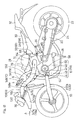
Fig. 1 is a side view showing a motorcycle having mounted thereon a combustion engine designed in accordance with a first preferred embodiment of the present invention; -
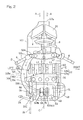
Fig. 2 is a schematic fragmentary top plan view of the motorcycle with a portion thereof removed; -
Fig. 3 is a perspective view, as viewed in a direction forwardly upwardly of the motorcycle, showing an important portion of the motorcycle; -
Fig. 4 is a perspective view of that important portion of the motorcycle as viewed rearwardly upwardly; -
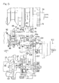
Fig. 5 illustrates an arrangement of shafts, used in a power train of the motorcycle, showing a supercharger device used therein; -
Fig. 6 is a schematic horizontal sectional view of the supercharger used in the power train; -
Fig. 7 is a schematic front elevational view of the motorcycle; -
Fig. 8 is a view similar toFig. 1 , showing the motorcycle having mounted thereon the combustion engine designed in accordance with a second preferred embodiment of the present invention; -
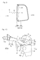
Fig. 9 is a schematic longitudinal sectional view showing a first modified form of an intake duct used in the combustion engine of the present invention; -
Fig. 10 is a schematic side view showing a second modified form of the intake duct used in the combustion engine of the present invention; and -
Fig. 11 is a schematic top plan view showing a third modified form of the intake duct used in the combustion engine of the present invention. - Preferred embodiments of the present invention will be hereinafter described in detail. It is, however, to be noted that the terms "left" and "right" used herein are to be understood as relative terms used to denote opposite directions or positions, respectively, as viewed from a vehicle driver then maneuvering the automotive vehicle.
-
Fig. 1 illustrates a side view showing a motorcycle, which is one kind of the saddle riding type vehicles and has mounted thereon a combustion engine designed in accordance with a first preferred embodiment of the present invention. The illustrated motorcycle frame structure FR has a front half frame section and a rear half frame sections, which are generally opposite to each other. The front half frame section includes amain frame 1, and the rear half frame section includes aseat rail 2 and areinforcement rail 2a. Theseat rail 2 and thereinforcement rail 2a are fitted to a rear frame portion of themain frame 1. Themain frame 1 has a front end formed integrally with a head pipe 4, and afront fork 8 is rotatably supported by such head pipe 4 through a steering shaft (not shown). Afront wheel 10 is mounted on a lower end portion of thefront fork 8, and asteering handlebar 6 is fixed to an upper end portion of thefront fork 8. In other words, the head pipe 4 functions as a handlebar post, and themain frame 1, which is a part of the motorcycle frame structure FR, extends from the head pipe 4 in a direction rearwardly of the motorcycle body. - On the other hand, a
swingarm bracket 12 is provided in a rear end portion of themain frame 1, which is a lower intermediate portion of the motorcycle frame structure FR, and aswingarm 20 is supported by theswingarm bracket 12 for movement up and down. Arear wheel 22 is supported by a rear end portion of theswingarm 20 for pivotal movement about apivot pin 23. - A motorcycle combustion engine E is mounted on the lower intermediate portion of the motorcycle frame structure FR and positioned on a front side of the
swingarm bracket 12. An engine power of the combustion engine E is transmitted to atransmitting mechanism 24 such as, for example, a substantially endless chain, and therear wheel 22 is driven through thistransmission mechanism 24. The combustion engine E is in the form of a parallel multicylinder engine in the form of, for example, a four-cylinder, four-cycle combustion engine. It is, however, to be noted that the type of the combustion engine E is not necessarily limited to that referred to above. - A rear
portion cushioning mechanism 25 is connected between therear frame 2 and theswingarm 20. This rearportion cushioning mechanism 25 serves to buffer a load imposed between therear wheel 22 and therear frame 2. Akickstand 26 is supported at a lower portion of theswingarm bracket 12 for movement between erected and folded position. Aradiator 27 for cooling an engine cooling water is disposed forwardly of the combustion engine. E. - A
fuel tank 28 is disposed on an upper portion of themain frame 1, and a driver'sseat 30 and a fellow passenger'sseat 32 are supported by therear frame 2. Also, afront cowling 34, made of a resinous material, is mounted on a front portion of the motorcycle body or motorcycle frame structure FR so as to cover an area ranging from forwardly of the head pipe 4 to opposite lateral portions of the front portion of the motorcycle body. Thefront cowling 34 has aheadlamp unit 36 mounted thereon. Thefront cowling 34 is formed with anair intake opening 38 for introducing the ambient air therethrough into the combustion engine E. Theair intake opening 38 is positioned below theheadlamp unit 36. - With the
air intake opening 38 open in a direction forwardly of the motorcycle body, the amount of air drawn towards the combustion engine E can be increased by the utilization of the wind pressure of the incoming wind A. Theair intake opening 38 is disposed in a front surface of thefront cowling 34 and positioned at a nose portion of thefront cowling 34 at which the highest wind pressure of the incoming wind is available. In the illustrated embodiment, theair intake opening 38 is shown as positioned below theheadlamp unit 36, but it may be positioned above theheadlamp unit 36, or at a position intermediate between two headlamps spaced apart from each other in a direction laterally of the motorcycle body in the case of any known twin headlamp structure. - The combustion engine E includes an engine driven
rotary shaft 39 extending in a direction parallel to the widthwise direction of the motorcycle body, acrankcase 40 supporting the engine drivenrotary shaft 39, acylinder block 42 protruding upwardly from thecrankcase 40 and having acylinder head 44 mounted on thecylinder block 42, a head covering 46 fitted to an upper portion of thecylinder head 44, and anoil pan 50 provided beneath thecrankcase 40. In this embodiment, thecrankcase 40 has a rear portion concurrently serving as a transmission casing. Thecylinder block 42 is somewhat tilted forwardly. The head covering 46 covers a cam mechanism (not shown) for intake and exhaust valves. Thecylinder head 44 has a rear portion provided with anair intake port 47. - An exhaust port at a front surface of the
cylinder head 44 is fluid connected with fourexhaust pipes 54. Those fourexhaust pipes 54 are merged together at a location beneath the combustion engine E and then fluid connected with anexhaust muffler 56, which is disposed on a right side of therear wheel 22. An electric generator (not shown) is connected at a laterally outer side of the engine drivenrotary shaft 39, specifically on the right side thereof in the illustrated embodiment, and a generator covering 58 covers the electric generator from an outer side. - As shown in
Fig. 2 , on the right side of the combustion engine E, a valve drivingforce transmitting mechanism 60 for transmitting the engine power of the combustion engine E to the intake and exhaust valves referred to previously is disposed. Although the illustrated embodiment is shown as utilizing a cam chain as the valve drivingforce transmitting mechanism 60, it is not necessarily limited thereto and a push rods or gears, for example, may be employed. It is to be noted that inFigs. 2 ,3 and4 , the motorcycle frame structure FR, thefuel tank 28 and anintake air chamber 74 as will be detailed later are not shown therein for the sake of clarity. - The
cylinder block 42 is formed with a combustionchamber defining segment 42a for defining a combustion chamber for each of the engine cylinders and a transmitting mechanism accommodating segment 42b for accommodating therein a part of a valve drivingforce transmitting mechanism 60 adjacent to the combustionchamber defining segment 42a. If as is the case with the embodiment now under discussion, a cam chain is used as the valve drivingforce transmitting mechanism 60, the transmitting mechanism accommodating segment 42b is formed as a cam chain tunnel. The combustionchamber defining segment 42a has a motorcycle widthwise intermediate position disposed in the vicinity of a longitudinal center line C of the motorcycle body that extends in a direction parallel to the longitudinal sense of the motorcycle. In other words, thecylinder block 42 has a distance L2 which is measured from the longitudinal center line C of the motorcycle body to a right side end portion where the transmitting mechanism accommodating segment 42b is formed, which distance L2 is greater than the distance L1 from the longitudinal center line C of the motorcycle body to a left side end portion, and does hence protrude towards laterally rightwardly of the motorcycle widthwise direction. - As shown in
Fig. 1 , asupercharger 62 is disposed rearwardly of thecylinder block 42 and above thecrankcase 40. Thissupercharger 62 forms an air intake portion through which the ambient air is drawn and is then supplied towards the combustion engine E. Thesupercharger 62 has asupercharger rotating shaft 64 extending in a direction widthwise of the motorcycle body, anintake port 66 open leftwards, and adischarge port 68 disposed at a portion of the combustion engine E intermediate of the motorcycle widthwise direction. Thedischarge port 68 is positioned rearwardly of thesupercharger rotating shaft 64. - The
intake port 66 of thesupercharger 62 is disposed above an upper surface of thecrankcase 40 and inwardly of a left side surface of thecylinder block 42 with respect to the motorcycle widthwise direction. Thisintake port 66 is fluid connected with anair intake duct 70. Thisair intake duct 70 serves to introduce the incoming wind A, then flowing forwardly of thecylinder block 42, into thesupercharger 62. Thesupercharger 62 and theair intake duct 70 cooperate with each other to form asupercharger device 69 operable to supply the air under pressure into the engine cylinder. The detail of theair intake duct 70 will be described later. - Referring now to
Fig. 3 , thedischarge port 68 of thesupercharger 62 opens upwardly. Anintake air chamber 74 is disposed between thedischarge port 68 and the air intake port 47 (best shown inFig. 1 ) of the combustion engine E. Theintake air chamber 74 serves to pool therein the intake air that is supplied from thesupercharger 62 to theair intake port 47 of each of the plurality of the engine cylinders. Theintake air chamber 74 extends over the substantially entire length of thecylinder block 42 in the motorcycle widthwise direction and is, as shown inFig. 4 , disposed upwardly of thesupercharger 62 and rearwardly of thecylinder block 42. - A
pipe 73 between thesupercharger 62 and theintake air chamber 74 is fluid connected at an intermediate portion of theintake air chamber 74 with respect to the motorcycle widthwise direction. Accordingly, the intake air from thesupercharger 62 shown inFig. 1 flows uniformly into the plurality of theair intake ports 47. Athrottle body 76 is disposed between theintake air chamber 74 and thecylinder head 44. In thisthrottle body 76, fuel is jetted into the intake air to form an air/fuel mixture, and this resultant air/fuel mixture is supplied into the cylinder. Thefuel tank 28 referred to previously is disposed above theintake air chamber 74 and thethrottle body 76. - The
supercharger 62 pressurize the air, which has been drawn through theintake port 66, and supplies it to the combustion engine E after the pressure has been increased and then discharged from thedischarge port 68. Accordingly, the amount of the intake air supplied to the combustion engine E can be increased. Thedischarge port 68 has an axial line that is tilted forwards and upwardly. By this design, the intake air can be smoothly guided towards theintake air chamber 74. As shown inFig. 2 , when thedischarge port 68 of thesupercharger 62 and the motorcycle widthwise intermediate position of the combustionchamber defining segment 42a of thecylinder block 42 are held at the substantially same position, an undesirable bias of the flow of the intake air towards each of the engine cylinder can be avoided. - As shown in
Fig. 5 , thecrankshaft 39, which is the rotary shaft of the combustion engine E referred to previously, is provided with acrank gear 80. Thecrank gear 80 is formed in an inner web at a location inwardly of aclutch gear 79. This crankgear 80 is meshed with adrive gear 84 to drive acountershaft 78. Asupercharger drive shaft 82 is disposed on one side opposite to thecrankshaft 39 with respect to thecountershaft 78. Thecountershaft 78 and thesupercharger drive shaft 82 have respective axes that extend parallel to thecrankshaft 39. Thedrive gear 84 is splined to thecountershaft 78 for rotation together therewith. Astarter gear 86 is relatively rotatably supported by thecountershaft 78, and one way clutch 85 is interposed between thedrive gear 84 and thestarter gear 86. - The
starter gear 86 is connected with astarter motor 90 through atorque limiter 88. Accordingly, when thestarter motor 90 revolves while the combustion engine E is in a halted condition, the one way clutch 85 is brought in a coupled position to allow a starting torque to be transmitted to thecrankshaft 39. Also, when the rotational speed of thecrankshaft 39 is driven at a speed higher than that of thestarter motor 90 after the engine E has been started, the one way clutch 85 is brought to a decoupled position and the power transmission from thecrankshaft 39 to thestarter motor 90 is inhibited. - A first
speed change gear 92, which has a reduced diameter, and a secondspeed change gear 94, which has a large diameter, are fixed to, for example, integrally formed with thecountershaft 78. In the embodiment now under discussion, although the speed change gears are employed two in number, they may be employed in any number equal to or greater than three. Thesupercharger drive shaft 82 is provided with a thirdspeed change gear 96, which has a large diameter, and a fourth speed change gear 98 which has a reduced diameter. The thirdspeed change gear 96 and the fourth speed change gear 98 are meshed respectively with the firstspeed change gear 92 and the secondspeed change gear 94. The third and fourth speed change gears 96 and 98 are rotatable relative to thesupercharger drive shaft 82 and relatively immovable in the axial direction. - A
sprocket 100 is provided on a right side end portion of thesupercharger drive shaft 82. Thissprocket 100 has achain 102 trained therearound. Thechain 102 forms a power transmitting unit for transmitting the power of the combustion engine E to thesupercharger 62. Via thechain 102, a rotational force of thecrankshaft 39 is transmitted from thecountershaft 78 and thesupercharger drive shaft 82 to aninput shaft 65 connected with thesupercharger rotating shaft 64. It is, however, to be noted that the method of driving thesupercharger 62 may not be necessarily limited to that described above. Thechain 102 is disposed on the right side of the motorcycle body, which is the side opposite to theintake port 66 of thesupercharger 62 with respect to the motorcycle widthwise direction. In the embodiment now under discussion, thecountershaft 78 and thesupercharger drive shaft 82 have been described and shown as directly connected with each other, but they may be indirectly connected with each other via, for example, an idle gear. The details of thesupercharger 62 will be discussed later. - A
shifter 104 is disposed at thesupercharger drive shaft 82 and between the thirdspeed change gear 96 and the fourth speed change gear 98. Theshifter 104 includes a shift ring 105, a shiftingfork 106 for maneuvering the shift ring 105, and a shift drum 108 for moving the shiftingfork 106 in parallel to thesupercharger drive shaft 82. - The shift ring 105 is splined to the
supercharger drive shaft 82 and, accordingly, the shift ring 105 is axially movable along thesupercharger drive shaft 82, but non-rotatable relative to thesupercharger drive shaft 82. The shift drum 108 is rotationally driven by ashifter drive unit 110 to axially move the shiftingfork 106. When one ofdogs engagement hole 105a defined in the shift ring 105, the shift ring 105 is selectively engaged relatively non-rotatably with one of the third and fourth speed change gears 96 and 98. - Via the selected
speed change gear 96 or 98, the power is transmitted from thecountershaft 78 to thesupercharger drive shaft 82. In other words, when a dogged connection establishes between the shift ring 105 and the thirdspeed change gear 96, the revolution of thecountershaft 78, that is, the revolution of thecrankshaft 39 is transmitted to thesupercharger drive shaft 82 at a large speed increasing ratio. On the other hand, when a dogged connection establishes between the shiftingfork 106 and the fourth speed change gear 98, the revolution of thecountershaft 78 is transmitted to thesupercharger drive shaft 82 at a small speed reducing ratio. The shifter deriveunit 110 is of a type having, for example, a servomotor, but it is not necessarily limited thereto. Thus, the rotational power of thecrankshaft 39 is transmitted from thecountershaft 78 to thesupercharger drive shaft 82 via the selectedspeed change gear 96 and 98. - The
shifter drive unit 110 is operable to move the shiftingfork 106 in the axial direction of the shift drum 108 in dependence on, for example, the number of revolutions of the combustion engine E so that one of the third and fourth speed change gears 96 and 98, which is appropriate for the number of revolutions, may be selected. More specifically, at a low rotating region of the combustion engine E, the dogged connection established between theshift ring 106 and the thirdspeed change gear 96 to allow the speed increasing ratio of thesupercharger 62 to increase so that the supercharge pressure, that is, the supercharged air amount can be increased to allow the engine torque to be gained at a low speed. On the other hand, at a high rotating region of the combustion engine E, setting is made in which the dogged connection established between the shift ring 105 and the fourth speed change gear 98 to allow the speed increasing ratio of thesupercharger 62 to be lowered to thereby avoid an excessive increase of the supercharged air amount so that a proper engine torque and a stabilized revolution can be obtained. -
Fig. 6 depicts a horizontal sectional diagram of thesupercharger 62 referred to above. As shown inFig. 6 , thesupercharger 62 includes apressure supply unit 61 and aspeed increasing unit 63. Thepressure supply unit 61 in turn includes animpeller 114 fixed to oneend portion 64a of thesupercharger rotating shaft 64. The opposite end portion 64b of thesupercharger rotating shaft 64 is connected with oneend portion 65a (the left side end portion with respect to the motorcycle widthwise direction) of theinput shaft 65 of thespeed increasing unit 63 via aplanetary gear device 112 which is a speed increaser or a set-up gear. In the description that follows, one end side of thesupercharger 62 is referred to as the left side with respect to the motorcycle widthwise direction whereas the other end side is referred to as the right side with respect to the motorcycle widthwise direction. The speed increaser may not necessarily used. - The
supercharger rotating shaft 64 is rotatably supported by ahousing 116. Acasing 124 for enclosing theimpeller 114 referred to above is fitted to a first flange 116a on one end side of thehousing 116 with the use of acasing fastening member 122 such as, for example, bolts. A second flange 116b on the other end side of thehousing 116 is fixed to acasing flange 120a of afixture casing 120, which is supported by the crankcase 40 (best shown inFig. 1 ) by means of ahousing fastening member 118. Accordingly, thesupercharger rotating shaft 64 and theimpeller 114 are covered by thehousing 116 and thecasing 124. Thecasing 124 is formed with thesuction port 66, open towards that one end side, and thedischarge port 68 open upwardly. - The
input shaft 65 is in the form of a hollow shaft, and is rotatably supported by thefixture casing 120 viabearings 123 at a portion thereof adjacent to the other end portion thereof and an intermediate portion. On the other hand, oneend portion 65a of theinput shaft 65 is rotatably supported by thehousing 116 via abearing 125. Spline serrations are formed on an outer peripheral surface of theother end portion 65b of theinput shaft 65. Via a one way clutch 128 mounted on this outer peripheral surface by means of the spline engagement, asprocket 130 is connected with theinput shaft 65. - The
chain 102 referred to previously is trained aroundteeth 132 of thesprocket 130, and the revolution of the supercharge drive shaft 82 (shown inFig. 5 ) is transmitted to theinput shaft 65 through thischain 102. Female threads are formed in an inner peripheral surface of theother end portion 65b of theinput shaft 65. The oneway clutch 128 is mounted on theother end portion 65b via awasher 136 by means of a head portion of abolt 134 threadingly engaged with the female threads. - As hereinabove described, the
planetary gear device 112 is disposed between theinput shaft 65 and thesupercharger rotating shaft 64, and is supported by both of thehousing 116 and thecasing 120.External threads 138 are formed on the other end portion 64b of thesupercharger rotating shaft 64, and a plurality ofplanetary gears 140 are meshed with those external threads while having been arranged in a circumferential direction. In other words, theexternal threads 138 formed on thesupercharger rotating shaft 64 function as a sun gear of theplanetary gear device 112. - Also, the
planetary gear 140 is meshed with an internal gear (ring gear) 142 of a large diameter on a radially outer side. Each of theplanetary gears 140 is rotatably supported by arespective carrier shaft 144 by means of a bearing 143. The bearing 143 is mounted on anannular flange portion 144 at the oneend portion 65a of theinput shaft 65. Accordingly, when theinput shaft 65 is rotated, theplanetary gears 140 undergo a revolution around thesupercharger rotating shaft 64. In other words, theinput shaft 65 rotates together with thecarrier shafts 144 of theplanetary gear device 112. - The
internal gear 142 is connected with afixture member 146, and thisfixture member 146 is secured to thehousing 116 by means of abolt 145. In other words, theinternal gear 142 is fixed. As such, theinternal gear 142 is fixed, thecarrier shaft 144 is connected with theinput shaft 65 for rotation together therewith, and the sun gear (external gear 138) is formed in thesupercharger rotating shaft 64 which serves as an output shaft. Theplanetary gear device 112 serves to increase the speed of rotation of theinput shaft 65 and transmits it to thesupercharger rotating shaft 64 at a positive rotation, that is, in the same direction of rotation as that of theinput shaft 65. - The structure of the
supercharger 62 is not necessarily limited to that shown and described in connection with the embodiment now under discussion. By way of example, the orientation of the axis of thesupercharger rotating shaft 64 may differ from that of the engine rotary shaft 39 (best shown inFig. 5 ). Also, thesupercharger 62 may be of a type that does not utilize the power from the combustion engine and may be of a type utilizing an electrically operated motor or the power from exhaust gases. Even in the internal structure of thesupercharger 62, it may be anything other than the impeller, such as, for example, a gear pump. In addition, the speed increasing mechanism may not be necessarily limited to that shown and described in connection with the embodiment now under discussion and theplanetary gear device 112 may be dispensed with. - The details of the
air intake duct 70, shown inFig. 1 , will now be described. Theair intake duct 70 is disposed on the left side, which is one side of the combustion engine E, and includes aram duct unit 147 on an upstream side and an airintake duct portion 148 on a downstream side. Theram duct unit 147 is supported by themain frame 1 with itsfront end opening 147a facing theair intake opening 38 in the previously describedcowling 34, and serves to increase the pressure of the air introduced from theopening 147a under the ram effect. The airintake duct portion 148 has afront end portion 148a fluid connected with arear end portion 147b of theram duct unit 147. Arear end portion 148b of the airintake duct portion 148 is fluid connected with theintake port 66 of thesupercharger 62. - The
front end opening 147a of theair intake duct 70 is held at a position higher in level than the upper surface of thecrankcase 40. More specifically, thefront end opening 147a is held at a position higher in level than thecylinder block 44 and theintake port 66 of thesupercharger 62. Thisfront end opening 147a is also positioned forwardly of a rear end of thefront wheel 10 and above an upper end of thefront wheel 10. Also, thefront end opening 147a is positioned forwardly of theradiator 27 and thefront fork 8. - As shown in
Fig. 2 , the airintake duct portion 148 has an inner side face 148d, which is smoothly curved, at a location forwardly of theair intake port 66 of thesupercharger 62, in a direction inwardly of the motorcycle widthwise direction towards the rear. Since the inner side face 148d of theair intake duct 70 is gradually varied inwardly towards the rear, it is possible to avoid a detachment of the flow of the intake air within theair intake duct 70. In the illustrated embodiment, anouter side face 148e of the airintake duct portion 148 is also curved. In other words, respective outermost portions of the inner side face 148d and theouter side face 148e of the airintake duct portion 148 are positioned forwardly of theair intake port 66 of thesupercharger 62. - More specifically, the air
intake duct portion 148 is so curved that the axis line 148c thereof may depict an arcuate shape. It is, however, to be noted that the airintake duct portion 148 works satisfactorily if smoothly curved and the axis line 148c may not necessarily follow the arcuate shape. The radius r of curvature of the axis line 148c of the airintake duct portion 148 is greater than the diameter D of the air intake duct 148 (that is, r > D), and is preferably twice or more of the diameter D (r ≥ 2D) and, more preferably, three or more of the diameter (r ≥ 3D). The center O of curvature is positioned inwardly of the outer side surface of the combustion engine E. - The curvature start position SP is positioned at a distance equal to or greater than the diameter D of the
intake duct portion 148 forwardly of theair intake port 66 of thesupercharger 62 and, specifically, rearwardly of thecylinder head 42. Thus, when the curvature starts from rearwardly of thecylinder head 42 that is positioned on the outermost side of the motorcycle body, the radius r of curvature of the curved portion of theair intake duct 70 can be increased while the interference between theair intake duct 70 and the combustion engine E is avoided. - In the saddle riding type vehicle such as, for example, the motorcycle, since the motorcycle widthwise dimension is small, it is difficult to increase the radius r of curvature, when viewed from top. However, as described above, positioning the curvature start position SP at a location forwardly of the
air intake port 66 of thesupercharger 62 is effective to permit the radius r of curvature to be increased. - The
ram duct unit 147 shown inFig. 1 is generally positioned forwardly of the head pipe 4 and is integrally fixed with, for example, thecowling 34 and theheadlamp unit 36. It is to be noted that the inside of the head pipe 4 may be used as a part of the air intake passage in theram duct unit 147. - The
front end opening 147a of theram duct unit 147 serves as an introducingport 70a of theair intake duct 70. The introducingport 70a of theair intake duct 70 is disposed in the vicinity of a front end portion, which is positioned most forwardly of a center portion of thecowling 34 with respect to the motorcycle widthwise direction, that is, in the vicinity of the point P of stagnation. Accordingly, the incoming wind A having a high pressure can be introduced into the cylinder. It is, however, to be noted that the introducingport 70a of theair intake duct 70 may be formed at any location other than the point P of stagnation.. - A
high order portion 70b, which is positioned above the introducingport 70a of a front end, is formed in an intermediate portion of theair intake duct 70, for example, an intermediate portion of theram duct unit 147 in the illustrated embodiment. In the illustrated embodiment, thehigh order portion 70b is provided in theram duct unit 147 at a location forwardly of the head pipe 4 and rearward of theheadlamp unit 36. Thehigh order portion 70b has anair cleaner 150 built therein. Theair cleaner 150 purifies the air to be introduced into thesupercharger 62. As described above, when theair cleaner 150 is disposed in thehigh order portion 70b, it is possible to avoid an undesirable ingress of water into theair cleaner 150. - In the embodiment now under discussion, the
air intake duct 70 passes outside of a region of rotation of thefront fork 8. Accordingly, theair intake duct 70 does not interfere thefront fork 8. Also, theair intake duct 70 passes above theradiator 27. Accordingly, theair intake duct 70 will not hamper the flow of the incoming wind A, which has passed theradiator 27, towards the side of the motorcycle body. As a result, the cooling performance of theradiator 27 can be maintained. It is, however, to be noted that theair intake duct 70 may pass outside of theradiator 27. Even in that case, it is preferred that theair intake duct 70 may be arranged so that it will not hamper the flow of the incoming wind A, which has passed theradiator 27. - The air
intake duct portion 148 is a portion positioned rearwardly of the head pipe 4. This airintake duct portion 148 is used to smoothly connect between theram duct unit 147 and thesupercharger 62, and is defined by, for example, a tubular body made of a resinous material. The airintake duct portion 148 is smoothly inclined downwards from theram duct unit 147 toward the rearward, and passes a lateral region of thecylinder head 44 and the head covering 46 at a location laterally of thecylinder block 42. - More specifically, a portion of the
air intake duct 70 that passes a space laterally of thecylinder block 42 has a lower end positioned downwardly of anupper end 44a of thecylinder head 44 and also downwardly of anupper end 42a of thecylinder block 42. In other words, when viewed from side, a portion of theair intake duct 70 and the combustion engine E overlap one above the other. An upper end of that portion passing the space laterally of thecylinder block 42 may be so made as to assume a position below the head covering 46 or thecylinder head 44. - The incoming wind A from the
air intake opening 38 passes through theram duct unit 147 and is, after having been purified by theair cleaner 150, introduced into thesupercharger 62 via the airintake duct portion 148. The incoming wind A so introduced into thesupercharger 62 is pressurized by thesupercharger 62, and is then introduced into the cylinder via theintake air chamber 74 and thethrottle body 76. - The air
intake duct portion 148 shown inFig. 2 includes afirst duct portion 152 and asecond duct portion 154. Thefirst duct portion 152 is inclined downwardly rearwardly from theram duct unit 147 and is also bulged leftwards (outside). Thisfirst duct portion 152 also passes a space on the lateral left side of thecylinder block 42 and downwardly of the upper end of thecylinder head 44 before it extends in a direction conforming to the longitudinal sense of the motorcycle body. Thesecond duct portion 154 is continued to a rear end of thefirst duct portion 152, then curved towards a center portion of the motorcycle widthwise direction and finally connected with theintake port 66 of thesupercharger 62 at a location rearwardly of thecylinder block 42. - As shown in
Fig. 1 , thefirst duct portion 152 of the airintake duct portion 148, when in the lateral region of the combustion engine E, passes above thecrankshaft 39 when viewed from side. Specifically, thefirst duct portion 152 passes above an upper surface of the generator covering 58, which is fitted to a left side portion of thecrankcase 40, and below the upper surface of thecylinder head 44 and thethrottle body 76. More specifically, the lower surface of the airintake duct portion 148 passes above the upper surface of the generator covering 58 and also above thecrankshaft 39. Also, the lateral region of the combustion engine E in thefirst duct portion 152 and a downstream portion positioned downstream thereof, when viewed from side, passes below theintake air chamber 74 at a height substantially level with thesecond duct portion 154. - As hereinabove described, the
first duct portion 152 of the airintake duct portion 148, in the engine lateral region, extends beneath the upper surface of thecylinder head 44, and thesecond duct portion 154 is disposed below the upper surface of thecylinder head 44. Accordingly, as compared with the case in which the duct passes above the upper surface of thecylinder head 44, there is no need to drastically bend the airintake duct portion 148 downwardly in order for it to be connected with theair intake opening 66 and, therefore, it is possible to secure a large radius of curvature of the airintake duct portion 148. - Also, since in the lateral region of the combustion engine E, the air
intake duct portion 148 pass below thethrottle body 76, interference with component parts such as, for example, a throttle valve drive mechanism, a sensor or the like which is formed on both side portions of thethrottle body 76 is avoided to allow the airintake duct portion 148 to be extended in the direction inwardly of the motorcycle widthwise direction as far as possible. - In addition, since the
first duct portion 152 extends above the generator covering 58, interference between the airintake duct portion 148 and the generator covering 58 can be avoided. Also, at the time of tumble of the motorcycle the generator covering 58 is first brought into collision against the road surface prior to the collision of the airintake duct portion 148 and, accordingly, the collision of the airintake duct portion 148 against the road surface can be relieved and, hence, impairment of theair intake duct 148 can be suppressed. In other words, as shown inFig. 7 , the airintake duct portion 148 is preferably disposed inwardly of the imaginary line V (bank angle) extending from the point of intersect between the road surface G and the mid-center plane C2, which passes through a motorcycle body center in the motorcycle widthwise direction, to the outermost side surface of the combustion engine E. - In the illustrated embodiment, the sectional shape of the
first duct portion 152 of the airintake duct portion 148 has been shown and described as a round sectional shape, but it may be other than the round sectional shape, such as, for example, a sectional shape in which a major axis extends in the up and down direction (vertical direction), specifically, an oval sectional shape or a D-sectioned shape (a shape in which opposite ends of the arch are connected together). Specifically, when as the duct sectional shape in the lateral region of the combustion engine E, the dimension in the up and down direction that is greater than that in the motorcycle widthwise direction is employed, it is possible to increase the passage surface area while avoiding an undesirable expansion in the motorcycle widthwise direction. - Also, as shown in
Fig. 2 , theair intake duct 70 is disposed on the left side which is opposite to the side where the clutch 48 is disposed and which is the same side as that of the drive chain (transmitting mechanism) 24 and thekickstand 26. Positioning on the same side as that of thekickstand 26 makes it possible for theair intake duct 70 to be less remarkable at the time of halt of the motorcycle. Also, although the valve drivingforce transmitting mechanism 60 comes to be disposed on the right side, the right side position can be made higher than the left side during the halt of the motorcycle, and therefore, oil within thecylinder head 44 can be prevented from leaking into a right side passage where the valve drivingforce transmitting mechanism 60 is accommodated. - It is, however, to be noted that the
air intake duct 70 may be disposed on the same side as the valve drivingforce transmitting mechanism 60. By way of example, where the intermediate position of thecylinder block 42 in the motorcycle widthwise direction is offset on one side of the widthwise direction relative to the longitudinal center line C of the motorcycle body, a space is available on the other side of thecylinder block 42 and, therefore, theair intake duct 70 may pass through the space formed on the other side of thecylinder block 42. Also, by designing the shape of theair intake duct 70 and/or applying a decorative paint to allow theair intake duct 70 to be disposed on the opposite side of thekickstand 26, theair intake duct 70 can be formed as an ornamental item during the halt of the motorcycle. - Also, the
second duct portion 154 is formed with anair reserving portion 156 positioned rearwardly of thecylinder block 42 and having a flow passage surface area that is set to a larger value than that of thefirst duct portion 152. Thus, formation of theair reservoir 156 which is a diametrically enlarged portion is effective to reduce the air sucking speed to increase the air intake efficiency. Also, the provision of theair reservoir 156 makes it possible to reduce the sectional surface area of the airintake duct portion 148 other than the diametrically enlarged portion down to a value smaller than theair intake port 66 of thesupercharger 62. However, the use of theair reservoir 156 may be dispensed with. - When the
crankshaft 39 shown inFig. 5 rotates, thecountershaft 78 rotates in association with thecrankshaft 39 due to the meshed relation between thedrive gear 84 and thecrank gear 80. When thecountershaft 78 rotates in the manner described above, thesupercharger drive shaft 82 is rotated through the transmission device. The rotation of thesupercharger drive shaft 82 results in rotation of theinput shaft 65 via thechain 102 and, also, rotation of thesupercharger rotating shaft 64 allows thesupercharger 62 to be started. - When the motorcycle runs, the incoming wind A shown in
Fig. 1 passes from theair intake opening 38 and then through theram duct unit 147 and is subsequently introduced into thesupercharger 62 after having been purified by theair cleaner 150. The incoming wind A so introduced into thesupercharger 62 is pressurized by the supercharge 62 and is then introduced into the combustion engine E via theintake air chamber 74 and thethrottle body 76. By such a cumulative effect of the ram pressure and the pressurization of thesupercharger 62, the high pressure intake air can be supplied to the combustion engine E. - In the construction hereinabove described, since the
air intake duct 70 extends from forwardly of the combustion engine E towards the rear thereof so as to pass on the left side of the combustion engine E, the possibility of the space above the combustion engine E being downtrodden by theair intake duct 70 can be avoided. As a result thereof, thefuel tank 28 disposed above the combustion engine E can have an increased capacity and, also, the degree of freedom in designing can be increased. Also, even positioning of theintake air chamber 74 upwardly of the combustion engine E allows thefuel tank 28 to secure a sufficient capacity. - As shown in
Fig. 2 , since the inner side face 148d of theair intake duct 70 is curved at the location forwardly of theair intake port 66 of thesupercharger 62, a smoothly curved path can be easily formed and the line resistance in the air intake passage can be reduced. When thesupercharger 62 is used, the flow speed of the intake air flowing in theair intake duct 70 becomes extremely high and the passage resistance will increase. However, since as described above the passage resistance can be reduced, the reduction of the engine output can be suppressed even where thesupercharger 62 is used. - Since the valve driving
force transmitting mechanism 60 is disposed laterally rightwardly of the combustion engine E and theair intake duct 70 passes the space left vacant on the left side, the space around the combustion engine E can be efficiently utilized. - As shown in
Fig. 1 , thesupercharger 62 is disposed above thecrankcase 40 and theair intake duct 70 passes the lateral region of the combustion engine E at a location below thecylinder head 44. Accordingly, when viewed from side, thefirst duct portion 152 of theair intake duct 70 can be fluid connected with thesupercharger 62 without thefirst duct portion 152 being markedly curved in the up and down direction at a location rearwardly of thecylinder head 44. - As shown in
Fig. 2 , theair intake port 66 of thesupercharger 62 is disposed inwardly of the left side surface of the combustion engine E with respect to the motorcycle widthwise direction, and thesecond duct portion 154 of theair intake duct 70 is formed with theair reserving portion 156. Therefore, the high pressure air can be reserved before theair intake port 66 of thesupercharger 62 and, accordingly, the output of the combustion engine E can be increased. Also, even although the channel surface area of thesecond duct portion 154 extending in a direction conforming to the motorcycle widthwise direction is increased, the dimension in the motorcycle widthwise direction does not increase, and therefore, theair reserving portion 156 can be accommodated within the width of the combustion engine E. - As shown in
Fig. 5 , thechain 102 for transmitting the power of the combustion engine E to thesupercharger 62 is disposed on the right side with respect to the motorcycle widthwise direction, which is opposite to the left side in which theair intake port 66 of thesupercharger 62 is oriented. Accordingly, the space around the combustion engine E can be further efficiently utilized with no interference occurring between theair intake duct 70, which is fluid connected with theair intake port 66, and thechain 102. - As shown in
Fig. 1 , theair intake port 66 of thesupercharger 62 is positioned at a location upwardly of the rear portion of thecrankcase 40, that is, at a location spaced a substantial distance rearwardly from thecylinder block 42. Also, theintake air chamber 74 is disposed substantially or generally intermediate between thesupercharger 62 and theair intake port 72 of the combustion engine E in a direction conforming to the forward and rearward direction. Moreover, thesecond duct portion 154 of theair intake duct 70, which is positioned in the lateral region of the combustion engine E and downstream thereof, extends below theintake air chamber 74. As a result, theair intake port 66 of thesupercharger 62 shown inFig. 2 is positioned a large distance rearwardly away from thecylinder block 42. Accordingly, after the passage laterally of the combustion engine E, theair intake duct 70 can be curved to have a relatively large radius of curvature. - In addition, positioning of the
air intake port 66 rearwardly makes it possible to allow thesupercharger 62 in its entirety, including thedischarge port 68, to be disposed rearwardly. Accordingly, the dimension of theintake air chamber 74, shown inFig. 1 , in the forward and rearward direction can be increased to allow the chamber capacity to be pulled in without increasing the dimension of theintake air chamber 74 in the up and down direction. Suppression of the dimension of theintake air chamber 74 in the up and down direction makes it possible to avoid the interference between theintake air chamber 74 and thesecond duct portion 154 which passes below theintake air chamber 74. As a result, the possibility of the space above the combustion engine E being downtrodden can be further avoided. - As shown in
Fig. 1 , thehigh order portion 70b positioned upwardly of the introducingport 70a of the front end of theair intake duct 70 is formed in the intermediate portion of theair intake duct 70 in the forward and rearward direction. Accordingly, an undesirable ingress of water entering the introducingport 70a together with the incoming wind A into thesupercharger 62 can be suppressed. - Also, the introducing
port 70a of theair intake duct 70 is held at a heightwise position substantially level with theair intake port 66 of thesupercharger 62. Accordingly, the introducingport 70a of theair intake duct 70 gets away from the road surface and, therefore, an undesirable ingress of, for example, rainwater and/or muddy water from the introducingport 70a can be suppressed. - As a modified form of the previously described first embodiment of the present invention, arrangement may be made that the
supercharger 62 be dispensed with and a downstream end portion of theair intake duct 70 is fluid connected with theintake air chamber 74 either directly or via a deflecting member such as, for example, funnel. In such case, theintake air chamber 74 forms an air intake portion from which the intake air is supplied to the combustion engine E. Even such modified form can exhibit effects similar to those afforded by the previously described first embodiment of the present invention. In other words, since noair intake duct 70 is disposed in the space above the combustion engine E, the degree of freedom in designing can be increased. Also, in the previously described first embodiment, at the site where thesupercharger 62 is disposed, any other component such as, for example, theintake air chamber 74 and theair cleaner 150 can be disposed and the degree of freedom in disposing the components is further increased. -
Fig. 8 illustrates a side view of the motorcycle having mounted thereon a combustion engine designed in accordance with a second preferred embodiment of the present invention. The motorcycle frame structure FR of this motorcycle includes a combustion engine E disposed at the intermediate portion of the motorcycle body, afront frame 1A supported by the combustion engine E and extending diagonally upwardly and forwardly from the combustion engine E in the vicinity of the center with respect to the motorcycle widthwise direction, and arear frame 2A supported by the combustion engine E and extending diagonally upwardly and rearwardly from the combustion engine. In other words, the combustion engine E forms a part of the motorcycle frame structure FR. - The head pipe 4 is formed integrally with a front end of the
front frame 1A, with the steering shaft (not shown) being rotatably supported by this head pipe 4, and thesteering handlebar 6 is fixed to this steering shaft. In other words, the head pipe 4 functions as a handlebar post, and thefront frame 1A, which is a part of the motorcycle frame structure FR, extends from the head pipe 4 in a direction rearwardly of the motorcycle body. It is to be noted that inFig. 8 , thecowling 34 is not shown. - Forked
arms 200 extending forwardly from the combustion engine E are supported by a front portion of thecrankcase 40 of the combustion engine E for movement up and down, and a hub steering mechanism (not shown) for steerably supporting thefront wheel 10 is fitted to left and right pairs ofarm pieces arms 200. Also, there are provided a steering mechanism (not shown) for steering thefront wheel 10 by means of the hub steering mechanism by transmitting the manipulation of the hub steering mechanism and a front suspension (not shown) for cushioning a load imposed on thefront wheel 10. Other structural features than those described above are similar to those afforded by the previously described embodiment and, therefore, effects similar to those afforded by the previously described embodiment can be obtained. - Also, the motorcycle according to the second embodiment is such that the combustion engine E forms a part of the motorcycle frame structure FR and, therefore, makes no use of the motorcycle frame structure FR on an outer side of the
cylinder block 42. Accordingly, the interference between the motorcycle frame structure FR and theair intake duct 70 is avoided, and theair intake duct 70 can be easily disposed laterally of the combustion engine E. Also, with the combustion engine E rendered to be a part of the motorcycle frame structure FR, there is no need to increase the rigidity of the frame that extends rearwardly from the head pipe 4 and, therefore, the degree of freedom of theair intake duct 70 can be further increased. - The
air intake duct 70 of the present invention can have one of other various shapes than that described hereinbefore in connection of the foregoing embodiment. By way of example, although in the foregoing embodiment the passage surface area of the airintake duct portion 148 of theair intake duct 70 remains constant, arrangement may be made to gradually decrease the passage surface area in a direction from front towards rear. Accordingly, the flow velocity of the intake air gradually increase from the upstream side towards the downstream side. As a result, without the flow velocity of the intake air being lowered in the vicinity of anair intake port 66 of thesupercharger 62, the high efficiency of thesupercharger 62 can be secured. Also, since the flow velocity of the intake air gradually increases, the turbulence of the flow is minimized and the air intake efficiency is high. - Also, although in the foregoing embodiment the air
intake duct portion 148 of theair intake duct 70 has been shown and described as having the round transverse sectional shape, the curved portion may have such a sectional shape that, as shown inFig. 9 , the dimension D1 in a direction conforming to the transverse direction perpendicular to the radial direction R may gradually decrease from the center (center of curvature) O of the curvature towards the outside of the radial direction of the curvature. According to this construction, the passage radially outwardly of the curvature within the inside of theair intake duct 70 will become narrow as compared with the passage radially inwardly of the curvature. Accordingly, the bias of the intake air in a direction outwardly of the radial direction R of the curvature by the effect of the centrifugal force is suppressed, and the flow of the intake air is uniformized within theair intake duct 70. With the uniformized flow of the intake air being introduced into theair intake port 66 of thesupercharger 62, an undesirable reduction in efficiency of thesupercharger 62 can be avoided. - Yet, as shown in
Fig. 9 , the airintake duct portion 148 of theair intake duct 70 may be of a leftwardly and rightwardly split construction comprised of aleft side half 148L and aright side half 148R. With this construction, theair intake duct 70 can be formed by means of a mold shaping. As a result, even when curvature is made not only in the up and down direction, but also in a leftward and rightward direction, theair intake duct 70 can be easily formed. - Also, as shown in
Fig. 10 , the undersurface of theair intake duct 70 may have alowermost portion 70d at an intermediate portion between the introducingport 70a at the front end and arear end portion 70c, and adrain hole 71 may be provided so as to extend completely through a duct wall of thelowermost portion 70d. Accordingly, even when rainwater ingresses into theair intake duct 70, the rainwater can be discharged from thedrain hole 71 before it reaches theair intake port 66 of thesupercharger 62 and, thus, the ingress of the rainwater into thesupercharger 62 is avoided. - In the example shown in
Fig. 10 , theair intake duct 70 has an upper surface of such a shape as to follow the undersurface. In other words, even the upper surface of theair intake duct 70 has the lowermost portion at the intermediate portion between the introducingport 70a at the front end and therear end portion 70c, and theair intake duct 70 as a whole has an V shaped configuration when viewed from side. Accordingly, an abrupt change of the passage surface area within theair intake duct 70 is suppressed. - Yet, as shown in
Fig. 11 , theheadlight unit 36 may be disposed at an intermediate portion of the motorcycle body with respect to the motorcycle widthwise direction, in which case the introducingport 70a and theair intake duct 70 are disposed on the outer side (left side so far shown inFig. 11 ) of theheadlight unit 36. InFig. 11 , an outer side end P1 of the introducingport 70a is shown as positioned on an outer side of an inner side face 70i of theair intake duct 70 over the entire area in the forward and rearward direction. Also, the introducingport 70a has an open edge inclined outwardly towards the rear. - In addition, as shown by the double dotted chain line in
Fig. 11 , theair intake duct 70 may have an additional introducingport 160 besides a leftside introducing port 70a. According to this construction, because of the presence of the additional introducingport 160, the amount of the incoming air A sucked increases. In such case, acleaner element 170 having, for example, a large passage surface area may be built therein at the junction between theram duct unit 147 and the airintake duct portion 148. Accordingly, the intake air I passes thecleaner element 170 at a site where the flow velocity is low and, therefore, the flow loss at the time of passage through thecleaner element 170 can be minimized. - Although in describing each of the foregoing embodiments, the
supercharger 62 or theintake air chamber 74 forms the air intake portion, it is not necessarily limited thereto and any other element such as, for example, the air cleaner or an introducing pipe of thethrottle body 76 may be rendered as the air intake portion. - Also, beside each of the embodiments hereinabove fully described, the present invention is applicable to the standard structure in which the combustion engine E is not used as a part of the motorcycle frame structure, for example, the structure in which the motorcycle frame structure extends from the handlebar post towards the rear of the motorcycle body on the inner side of the
air intake duct 70 with respect to the motorcycle widthwise direction, that is, the structure in which the frame extends above or below the combustion engine E. Specifically, the present invention is applicable to a cradle frame, a diamond frame or a backbone frame. In addition, it may be a twin tube frame, in which the motorcycle frame structure is disposed laterally of the combustion engine E. In such case, it is preferred to configure the structure in which arrangement is made to permit the incoming wind A to flow within the motorcycle frame structure so as to enable the air intake duct and the motorcycle frame to be concurrently served. - Although the present invention has been fully described in connection with the preferred embodiments thereof with reference to the accompanying drawings which are used only for the purpose of illustration, those skilled in the art will readily conceive numerous changes and modifications within the framework of obviousness upon the reading of the specification herein presented of the present invention. By way of example, while in the foregoing embodiment of the present invention the
air intake duct 70 has been shown and described as passing on the left side of the combustion engine E, theair intake duct 70 may pass on the right side of the combustion engine E or on both of the left and right sides of the combustion engine E. While the direction of rotation of theimpeller 114 may change depending on whether theair intake duct 70 passes on the left side of the combustion engine E or whether theair intake duct 70 passes on the right side of the combustion engine E, it can be accommodated with no need to considerably change thesupercharger 62, if the arrangement of the gears in theplanetary gear device 112 is altered. Also, in place of the alteration of the arrangement of the gears of theplanetary gear device 112, the direction of rotation of theimpeller 114 may be changed by interposing an idle gear and/or altering the power transmitting path. - Also, although in the foregoing embodiment the
air cleaner 150 has been shown and described as positioned in the vicinity of the head pipe 4, theair reserving portion 156 rearwardly of thecylinder block 42 may be used as an air cleaner chamber. Accordingly, the degree of freedom in designing increases further. Also, the duct structure of the present invention may be applied to any other saddle riding type vehicle other than the motorcycle and, specifically applied to a three wheeled automobile or a four wheeled automobile. - Accordingly, such changes and modifications are, unless they depart from the scope of the present invention as delivered from the claims annexed hereto, to be construed as included therein.
-
- 4
- Head pipe (Handle post)
- 39
- Crankshaft (Engine rotary shaft)
- 40
- Crankcase
- 42
- Cylinder block
- 44
- Cylinder head
- 60
- Valve driving force transmitting mechanism
- 62
- Supercharger (Air intake portion)
- 66
- Air intake port
- 68
- Discharge port
- 69
- Supercharger device
- 70
- Intake air duct
- 70a
- Introducing port
- 70b
- High order portion
- 72
- Inlet port
- 74
- Intake air chamber
- 102
- Power transmitting unit
- 152
- First duct portion
- 154
- Second duct portion
- 156
- Air reserving portion
- E
- Combustion engine
- FR
- Motorcycle frame structure
Claims (12)
- An engine mounted on a saddle riding type vehicle and having an engine rotary shaft extending in a widthwise direction of a vehicle body, which engine comprises:a crankcase to support the engine rotary shaft;a cylinder block to protrude upwardly from the crankcase;a cylinder head mounted on the cylinder block;an air intake portion disposed rearwardly of the cylinder block and operable to supply an intake air to the engine; andan air intake duct fluid connected with an air intake port of the air intake portion and operable to guide an incoming wind, which flows forwardly of the engine, towards the air intake portion; in whichthe air intake port is positioned below an upper end of the cylinder head;the air intake duct passes a lateral space of the cylinder block and below the cylinder head; andthe air intake duct has an inner side surface with respect to the widthwise direction, the inner side face being curved at a position forwardly of the air intake port of the air intake portion in a direction inwardly of the vehicle widthwise direction towards a rear.
- The engine mounted on the saddle riding type vehicle as claimed in claim 1, wherein the air intake portion is a supercharger to supply an intake air under pressure.
- The engine mounted on the saddle riding type vehicle as claimed in claim 2, wherein the supercharger is positioned above the crankcase.
- The engine mounted on the saddle riding type vehicle as claimed in claim 2 or 3, further comprising a power transmitting unit to transmit a power of the engine to the supercharger, the power transmitting unit being disposed on one side opposite to the air intake port of the supercharger with respect to the vehicle widthwise direction.
- The engine mounted on the saddle riding type vehicle as claimed in any one of claims 2 to 4, wherein the air intake port of the supercharger is positioned above a rear portion of the crankcase,
wherein an intake air chamber is disposed between a discharge port of the supercharger and the air intake port of the engine in a direction conforming to a forward and rearward direction,
wherein the intake air is introduced into the air intake port after having flown from the supercharger and then through the intake air chamber, and
wherein a downstream portion of the air intake duct extends below the intake air chamber, which downstream portion is positioned at the lateral region of the cylinder block and at its downstream side. - The engine mounted on the saddle riding type vehicle as claimed in any one of claims 1 to 5, wherein the air intake duct has an introducing port defined at a front end thereof, the introducing port being positioned at a heightwise position level with the air intake port of the air intake portion or above it.
- The engine mounted on the saddle riding type vehicle as claimed in any one of claims 1 to 6, wherein a lowermost portion of an undersurface of the air intake duct is provided at an intermediate of the air intake duct with respect to the forward and rearward direction,
wherein a drain hole is provided in the lowermost portion. - The engine mounted on the saddle riding type vehicle as claimed in any one of claims 1 to 7, wherein the air intake duct is disposed on one side of the engine and further comprising a valve driving force transmitting mechanism to transmit the power of the engine into intake and exhaust valves, the valve driving force transmitting mechanism being disposed on the other side opposite to such one side of the engine.
- The engine mounted on the saddle riding type vehicle as claimed in any one of claims 1 to 8, wherein the air intake duct comprises:a first duct portion, which extends in a forward and rearward direction of the vehicle body while passing on one side of the engine from forwardly of the vehicle body; anda second duct portion which is continued to a rear end of the first duct portion and is curved in towards an inner side of the vehicle body, the second duct portion being fluid connected with the air intake port at a location rearwardly of the cylinder block, wherein:the air intake port is disposed on an inner side of the one side of the engine with respect to a vehicle widthwise direction; andthe second duct portion is formed with an air reserving portion having a passage surface area that is set to be greater than the first duct portion.
- The engine mounted on the saddle riding type vehicle as claimed in any one of claims 1 to 9, wherein at an intermediate portion of the air intake duct, a high order portion positioned above the introducing port at the front end of the air intake duct is formed.
- The engine mounted on the saddle riding type vehicle as claimed in any one of claims 1 to 10, which engine is mounted on an automotive vehicle having an vehicle frame structure, the vehicle frame structure extending from a handlebar post towards the rear of the vehicle body on an inner side of a side surface of the engine on that side in which the air intake duct is disposed.
- A motorcycle which comprises:the engine as defined in any one of claims 1 to 11; anda front wheel support arm extending forwardly from a vehicle frame structure to support the front wheel at a location below the air intake duct.
Applications Claiming Priority (2)
| Application Number | Priority Date | Filing Date | Title |
|---|---|---|---|
| JP2012155462 | 2012-07-11 | ||
| PCT/JP2013/068910 WO2014010647A1 (en) | 2012-07-11 | 2013-07-10 | Saddle-ridden-vehicle engine |
Publications (3)
| Publication Number | Publication Date |
|---|---|
| EP2873847A1 true EP2873847A1 (en) | 2015-05-20 |
| EP2873847A4 EP2873847A4 (en) | 2016-05-18 |
| EP2873847B1 EP2873847B1 (en) | 2018-09-19 |
Family
ID=49916095
Family Applications (5)
| Application Number | Title | Priority Date | Filing Date |
|---|---|---|---|
| EP13817464.4A Active EP2878803B1 (en) | 2012-07-11 | 2013-07-10 | Motorcycle with air intake duct |
| EP13815957.9A Active EP2873847B1 (en) | 2012-07-11 | 2013-07-10 | Saddle-ridden-vehicle |
| EP13816162.5A Active EP2878800B1 (en) | 2012-07-11 | 2013-07-10 | Air intake duct for saddle-ridden vehicle |
| EP13817431.3A Active EP2878802B1 (en) | 2012-07-11 | 2013-07-10 | Saddle-ridden vehicle engine |
| EP13816960.2A Active EP2878801B1 (en) | 2012-07-11 | 2013-07-10 | Air intake duct of saddle-ridden vehicle |
Family Applications Before (1)
| Application Number | Title | Priority Date | Filing Date |
|---|---|---|---|
| EP13817464.4A Active EP2878803B1 (en) | 2012-07-11 | 2013-07-10 | Motorcycle with air intake duct |
Family Applications After (3)
| Application Number | Title | Priority Date | Filing Date |
|---|---|---|---|
| EP13816162.5A Active EP2878800B1 (en) | 2012-07-11 | 2013-07-10 | Air intake duct for saddle-ridden vehicle |
| EP13817431.3A Active EP2878802B1 (en) | 2012-07-11 | 2013-07-10 | Saddle-ridden vehicle engine |
| EP13816960.2A Active EP2878801B1 (en) | 2012-07-11 | 2013-07-10 | Air intake duct of saddle-ridden vehicle |
Country Status (5)
| Country | Link |
|---|---|
| US (5) | US9850863B2 (en) |
| EP (5) | EP2878803B1 (en) |
| JP (5) | JP6043353B2 (en) |
| CN (5) | CN104520573B (en) |
| WO (5) | WO2014010649A1 (en) |
Cited By (3)
| Publication number | Priority date | Publication date | Assignee | Title |
|---|---|---|---|---|
| ITUA20161485A1 (en) * | 2016-03-09 | 2017-09-09 | Madex S R L S | OVERHEAD SYSTEM FOR ENDOTHERMIC MOTORS |
| IT201700060987A1 (en) * | 2017-06-05 | 2018-12-05 | Vins S R L | MOTORCYCLE WITH LIQUID-COOLED ENGINE |
| EP3578404A1 (en) * | 2018-06-07 | 2019-12-11 | Kawasaki Jukogyo Kabushiki Kaisha | Saddle-riding vehicle |
Families Citing this family (34)
| Publication number | Priority date | Publication date | Assignee | Title |
|---|---|---|---|---|
| WO2014010636A1 (en) * | 2012-07-11 | 2014-01-16 | 川崎重工業株式会社 | Engine with supercharger |
| JP6043353B2 (en) | 2012-07-11 | 2016-12-14 | 川崎重工業株式会社 | Saddle-type vehicle engine |
| WO2014097775A1 (en) * | 2012-12-17 | 2014-06-26 | 川崎重工業株式会社 | Engine supercharger |
| JP6196667B2 (en) * | 2013-05-17 | 2017-09-13 | 川崎重工業株式会社 | Saddle riding vehicle |
| US9222405B2 (en) * | 2013-07-08 | 2015-12-29 | Massachusetts Institute Of Technology | Turbocharged single cylinder internal combustion engine using an air capacitor |
| JP5968348B2 (en) * | 2013-07-31 | 2016-08-10 | 本田技研工業株式会社 | Vehicle air cleaner device |
| EP3156314B1 (en) | 2014-06-16 | 2020-05-27 | Kawasaki Jukogyo Kabushiki Kaisha | Air intake duct for motorcycle |
| JP6366141B2 (en) * | 2015-05-29 | 2018-08-01 | 本田技研工業株式会社 | Saddle riding |
| CN106704050B (en) * | 2015-07-27 | 2019-03-29 | 长城汽车股份有限公司 | Air filter intake line |
| US10167767B2 (en) | 2015-10-27 | 2019-01-01 | Suzuki Motor Corporation | Motorcycle and saddle-ridden type vehicle |
| US10618404B2 (en) | 2016-01-29 | 2020-04-14 | Bombardier Recreational Products Inc. | Vehicle having dual air intake systems |
| JP6235634B2 (en) * | 2016-02-22 | 2017-11-22 | 本田技研工業株式会社 | Air cleaner structure in saddle riding type vehicle |
| US10352281B2 (en) * | 2016-07-08 | 2019-07-16 | Kawasaki Jukogyo Kabushiki Kaisha | Manufacturing method of head box of motorcycle, and air-intake device of motorcycle |
| JP6315045B2 (en) * | 2016-09-06 | 2018-04-25 | マツダ株式会社 | Water-reduction structure for vehicle engines |
| JP6490643B2 (en) * | 2016-09-30 | 2019-03-27 | 本田技研工業株式会社 | Electrical component support structure for saddle-ride type vehicles |
| DE102016220301B3 (en) * | 2016-10-18 | 2017-06-29 | Bayerische Motoren Werke Aktiengesellschaft | Motorcycle intake air duct for a motorcycle engine |
| JP6879711B2 (en) * | 2016-11-02 | 2021-06-02 | 川崎重工業株式会社 | Intake chamber structure |
| DE102016221793B3 (en) * | 2016-11-08 | 2017-12-28 | Bayerische Motoren Werke Aktiengesellschaft | Motorcycle with a device for the intake of charge air for a motorcycle engine |
| JP6924109B2 (en) * | 2017-09-28 | 2021-08-25 | 本田技研工業株式会社 | Seat structure for saddle-riding vehicles |
| AU201811306S (en) * | 2018-03-06 | 2018-03-28 | Safari R&D Pty Ltd | Air intake snorkel for a vehicle |
| JP7008837B2 (en) * | 2018-09-25 | 2022-01-28 | 本田技研工業株式会社 | Power unit for saddle-riding vehicles |
| JP6816080B2 (en) * | 2018-09-28 | 2021-01-20 | 本田技研工業株式会社 | Vehicle front structure |
| JP7046783B2 (en) * | 2018-11-16 | 2022-04-04 | 本田技研工業株式会社 | Saddle-type vehicle |
| JP6865728B2 (en) * | 2018-12-21 | 2021-04-28 | 川崎重工業株式会社 | Saddle-type vehicle |
| JP2020131839A (en) * | 2019-02-15 | 2020-08-31 | 本田技研工業株式会社 | Vehicle intake duct structure |
| USD883331S1 (en) * | 2019-03-24 | 2020-05-05 | Safari R&D Pty Ltd | Air intake snorkel for a vehicle |
| JP6906562B2 (en) * | 2019-04-12 | 2021-07-21 | 本田技研工業株式会社 | Exhaust structure of vehicle battery unit |
| JP7153606B2 (en) * | 2019-05-14 | 2022-10-14 | カワサキモータース株式会社 | Intake duct for saddle type vehicle |
| USD896844S1 (en) * | 2019-05-20 | 2020-09-22 | Safari R&D Pty Ltd | Air intake snorkel for a vehicle |
| USD882637S1 (en) * | 2019-07-24 | 2020-04-28 | Safari R&D Pty Ltd | Air intake snorkel for a vehicle |
| JP7287261B2 (en) * | 2019-12-18 | 2023-06-06 | トヨタ紡織株式会社 | intake duct |
| CN115871792B (en) * | 2021-09-29 | 2026-01-13 | 浙江春风动力股份有限公司 | All-terrain vehicle |
| US12286188B2 (en) * | 2021-10-01 | 2025-04-29 | Kawasaki Motors, Ltd. | Saddle riding vehicle |
| CN115788713B (en) * | 2022-11-25 | 2025-07-01 | 广西玉柴机器股份有限公司 | An engine and supercharger, air intake pipe, supercharger connection structure |
Family Cites Families (83)
| Publication number | Priority date | Publication date | Assignee | Title |
|---|---|---|---|---|
| US1305174A (en) | 1919-05-27 | sutsh | ||
| US1974110A (en) | 1932-12-21 | 1934-09-18 | Frank R Higley | Curved conduit |
| GB510738A (en) * | 1938-03-22 | 1939-08-08 | James Reginald Ferriday | Improvements in and relating to saddles and pillion seats for motor cycles |
| GB688738A (en) * | 1951-04-07 | 1953-03-11 | Feridax Ltd | Improvements relating to combined saddles and pillion seats for motor cycles |
| DE1528691A1 (en) * | 1966-03-05 | 1969-07-10 | Neyrpic Ets | Centrifugal pump intake manifold |
| JPS51131513U (en) * | 1975-04-14 | 1976-10-23 | ||
| JPS5713231A (en) * | 1980-06-26 | 1982-01-23 | Honda Motor Co Ltd | Super charger in motorcycle |
| JPS5749020A (en) * | 1980-09-05 | 1982-03-20 | Honda Motor Co Ltd | Turbo supercharger in internal combustion engine |
| JPS5755223A (en) * | 1980-09-16 | 1982-04-02 | Yamaha Motor Co Ltd | Intake device for engine in motorcycle |
| US4427087A (en) | 1981-01-14 | 1984-01-24 | Honda Giken Kogyo Kabushiki Kaisha | Motorcycle provided with an engine having a supercharger |
| US4550794A (en) | 1981-01-14 | 1985-11-05 | Honda Giken Kogyo Kabushiki Kaisha | Motorcycle having an engine with a supercharger |
| JPS57124027A (en) | 1981-01-24 | 1982-08-02 | Honda Motor Co Ltd | Motorcycle with engine with turbo-supercharger |
| JPS57137531A (en) * | 1981-02-20 | 1982-08-25 | Kokusai Denshin Denwa Co Ltd <Kdd> | Excavating method and device for ditch in bottom of water |
| JPS6338151Y2 (en) * | 1981-02-21 | 1988-10-07 | ||
| US4433751A (en) * | 1981-12-09 | 1984-02-28 | Pratt & Whitney Aircraft Of Canada Limited | Sound suppressor liner |
| US4705463A (en) | 1983-04-21 | 1987-11-10 | The Garrett Corporation | Compressor wheel assembly for turbochargers |
| GB8318604D0 (en) * | 1983-07-08 | 1983-08-10 | Newsome Air Conditioning | Cooling apparatus |
| JPS6055526U (en) * | 1983-09-26 | 1985-04-18 | 本田技研工業株式会社 | motorcycle |
| DE3531782A1 (en) | 1985-09-06 | 1987-03-19 | Teves Gmbh Alfred | HYDRAULIC BRAKE SYSTEM WITH SLIP CONTROL |
| JPH0674250B2 (en) | 1985-09-12 | 1994-09-21 | 住友精化株式会社 | Method for producing thiocarbamate derivative |
| JPH0213739Y2 (en) * | 1985-10-08 | 1990-04-16 | ||
| JPS6291967A (en) | 1985-10-18 | 1987-04-27 | Fuji Xerox Co Ltd | Controller for copying machine |
| JPS63121769A (en) | 1986-11-10 | 1988-05-25 | Japan Radio Co Ltd | Ppi sweep bearing error correcting circuit in radar indicator |
| JPS63121769U (en) * | 1987-01-30 | 1988-08-08 | ||
| JPS6447975A (en) | 1987-08-19 | 1989-02-22 | Nec Corp | Testing of integrated circuit |
| JPS6447975U (en) * | 1987-09-21 | 1989-03-24 | ||
| JPS6488059A (en) | 1987-09-29 | 1989-04-03 | Matsushita Electric Industrial Co Ltd | Hot water storage type hot water heater |
| JPH089413Y2 (en) * | 1987-12-04 | 1996-03-21 | 大豊工業株式会社 | Intake air connector |
| JPH022935A (en) * | 1988-06-20 | 1990-01-08 | Tosoh Corp | Angiotensin measuring method |
| JPH0252935A (en) | 1988-08-12 | 1990-02-22 | Noritz Corp | Hot water supply device for bath |
| JPH0270920A (en) * | 1988-09-02 | 1990-03-09 | Yamaha Motor Co Ltd | Motorcycle equipped with engine having supercharger |
| JPH0734176Y2 (en) * | 1988-10-07 | 1995-08-02 | 日野自動車工業株式会社 | Turbocharger intake system |
| JPH02175489A (en) * | 1988-12-28 | 1990-07-06 | Yamaha Motor Co Ltd | Suction device motorcycle |
| JP2986849B2 (en) * | 1990-06-09 | 1999-12-06 | ヤマハ発動機株式会社 | Motorcycle engine intake system |
| US5188510A (en) * | 1990-11-21 | 1993-02-23 | Thomas R. Norris | Method and apparatus for enhancing gas turbo machinery flow |
| JP3200770B2 (en) * | 1991-10-24 | 2001-08-20 | ヤマハ発動機株式会社 | Motorcycle |
| JP2799930B2 (en) * | 1992-10-29 | 1998-09-21 | 本田技研工業株式会社 | Motorcycle motorcycle intake system |
| JPH0769265A (en) * | 1993-06-30 | 1995-03-14 | Yamaha Motor Co Ltd | Intake device for motorcycles |
| JPH0738067A (en) | 1993-07-19 | 1995-02-07 | Toshiba Corp | Method for manufacturing semiconductor device |
| JPH07247928A (en) * | 1994-03-11 | 1995-09-26 | Nissan Diesel Motor Co Ltd | Engine intake manifold |
| JP3815519B2 (en) * | 1997-03-31 | 2006-08-30 | 豊田合成株式会社 | Intake air duct |
| JPH10331733A (en) * | 1997-05-28 | 1998-12-15 | Yamaha Motor Co Ltd | Motorcycle air intake system |
| JP2000233782A (en) * | 1999-02-15 | 2000-08-29 | Honda Motor Co Ltd | Air intake structure for small vehicles |
| US6190432B1 (en) | 1999-02-26 | 2001-02-20 | Donaldson Company, Inc. | Filter arrangement; sealing system; and methods |
| CN1201845C (en) * | 1999-02-26 | 2005-05-18 | 唐纳森公司 | Sealing systems for filters |
| JP3122437B1 (en) * | 1999-09-21 | 2001-01-09 | 川崎重工業株式会社 | Vehicle engine intake system |
| JP3811590B2 (en) * | 2000-03-30 | 2006-08-23 | 本田技研工業株式会社 | Air cleaner device for vehicles |
| JP4367878B2 (en) * | 2000-07-31 | 2009-11-18 | 本田技研工業株式会社 | Intake duct for motorcycle |
| JP2002122097A (en) | 2000-10-17 | 2002-04-26 | Shigeru Nagano | Suction port structure of turbo type blower |
| GB2391265A (en) | 2002-07-13 | 2004-02-04 | Imra Europ S A Uk Res Ct | Compressor inlet with swirl vanes, inner sleeve and shut-off valve |
| US6848528B2 (en) | 2002-08-13 | 2005-02-01 | Brp-Rotax Gmbh & Co. Kg | Lubrication system for a four cycle engine |
| CA2461325C (en) | 2003-03-31 | 2007-09-25 | Honda Motor Co., Ltd. | Intake apparatus for engine |
| JP4474111B2 (en) | 2003-03-31 | 2010-06-02 | 本田技研工業株式会社 | Motorcycle |
| JP4340500B2 (en) | 2003-09-09 | 2009-10-07 | 川崎重工業株式会社 | Intake device for motorcycle |
| JP2005138820A (en) | 2003-10-16 | 2005-06-02 | Yamaha Motor Co Ltd | Saddle riding |
| DE10350133A1 (en) | 2003-10-28 | 2005-06-23 | International Engine Intellectual Property Company, LLC., Warrenville | Internal combustion engine with at least two cylinder blocks |
| JP2006017090A (en) * | 2004-07-05 | 2006-01-19 | Yamaha Motor Co Ltd | engine |
| JP4607640B2 (en) | 2005-03-29 | 2011-01-05 | 本田技研工業株式会社 | Aircraft intake system |
| JP2006282143A (en) * | 2005-04-05 | 2006-10-19 | Toyoda Gosei Co Ltd | Air intake member |
| US7407031B2 (en) * | 2005-06-01 | 2008-08-05 | Yamaha Hatsudoki Kabushiki Kaisha | All terrain vehicle |
| JP4684041B2 (en) * | 2005-08-03 | 2011-05-18 | 川崎重工業株式会社 | Motorcycle |
| JP4431531B2 (en) * | 2005-09-13 | 2010-03-17 | 日産ディーゼル工業株式会社 | Airflow noise reduction device for turbocharger |
| FR2895463B1 (en) * | 2005-12-23 | 2013-08-16 | Renault | AIR INTAKE DUCT OF A CYLINDER OF AN INTERNAL COMBUSTION ENGINE AND CORRESPONDING CYLINDER HEAD |
| US7549493B1 (en) * | 2006-02-28 | 2009-06-23 | Jones Daniel W | Wet belt supercharger drive for a motorcycle |
| JP2008207694A (en) * | 2007-02-27 | 2008-09-11 | Honda Motor Co Ltd | Vehicle intake passage structure |
| WO2009052170A2 (en) * | 2007-10-19 | 2009-04-23 | Borgwarner Inc. | Duct for changing direction of flow, particularly for turbocharger compressor inlet |
| JP5236401B2 (en) * | 2008-09-05 | 2013-07-17 | ヤマハ発動機株式会社 | Motorcycle |
| JP5129712B2 (en) | 2008-09-30 | 2013-01-30 | 本田技研工業株式会社 | Radiator mounting structure for motorcycles |
| WO2011046096A1 (en) * | 2009-10-14 | 2011-04-21 | 川崎重工業株式会社 | Engine supercharger drive device |
| WO2011046098A1 (en) * | 2009-10-14 | 2011-04-21 | 川崎重工業株式会社 | Engine supercharging device |
| EP2517953B1 (en) | 2009-12-24 | 2020-01-01 | Kawasaki Jukogyo Kabushiki Kaisha | Two-wheeled motor vehicle with supercharger |
| EP2520782B1 (en) * | 2009-12-29 | 2016-04-13 | Kawasaki Jukogyo Kabushiki Kaisha | Supercharger intake duct |
| JP5419758B2 (en) * | 2010-03-10 | 2014-02-19 | 本田技研工業株式会社 | Intake device for motorcycle |
| CN102869874B (en) * | 2010-03-24 | 2015-04-08 | 本田技研工业株式会社 | Arrangement structure of an air intake system of a straddle type vehicle |
| JP2011202595A (en) * | 2010-03-25 | 2011-10-13 | Honda Motor Co Ltd | Intake structure for saddle-ride type vehicle |
| JP5604960B2 (en) * | 2010-04-27 | 2014-10-15 | スズキ株式会社 | Intake duct structure for motorcycles |
| DE102010038634A1 (en) * | 2010-07-29 | 2012-02-02 | Poroson Gmbh | Air filter for suction system of internal combustion engine of vehicle, has sound damping device comprising circumferential wall within which sound damping element is arranged, where sound damping element runs in axis direction of wall |
| JP5747483B2 (en) | 2010-11-16 | 2015-07-15 | 株式会社Ihi | Low pressure loop EGR device |
| JP5930376B2 (en) * | 2012-02-16 | 2016-06-08 | 本田技研工業株式会社 | Saddle riding vehicle |
| JP5787790B2 (en) | 2012-02-29 | 2015-09-30 | 三菱重工業株式会社 | Intake pipe structure of centrifugal fluid machinery |
| JP6043353B2 (en) * | 2012-07-11 | 2016-12-14 | 川崎重工業株式会社 | Saddle-type vehicle engine |
| JP6122820B2 (en) * | 2014-09-30 | 2017-04-26 | 本田技研工業株式会社 | Saddle riding type vehicle |
| JP5997307B2 (en) * | 2015-02-25 | 2016-09-28 | 本田技研工業株式会社 | Exhaust structure of saddle-ride type vehicle |
-
2013
- 2013-07-10 JP JP2014524854A patent/JP6043353B2/en active Active
- 2013-07-10 CN CN201380036432.1A patent/CN104520573B/en active Active
- 2013-07-10 WO PCT/JP2013/068912 patent/WO2014010649A1/en not_active Ceased
- 2013-07-10 EP EP13817464.4A patent/EP2878803B1/en active Active
- 2013-07-10 CN CN201380036434.0A patent/CN104428525B/en active Active
- 2013-07-10 WO PCT/JP2013/068913 patent/WO2014010650A1/en not_active Ceased
- 2013-07-10 JP JP2014524853A patent/JP5993949B2/en active Active
- 2013-07-10 JP JP2014524852A patent/JP5997273B2/en active Active
- 2013-07-10 CN CN201380036461.8A patent/CN104520575B/en active Active
- 2013-07-10 WO PCT/JP2013/068914 patent/WO2014010651A1/en not_active Ceased
- 2013-07-10 CN CN201380036263.1A patent/CN104520554B/en active Active
- 2013-07-10 WO PCT/JP2013/068911 patent/WO2014010648A1/en not_active Ceased
- 2013-07-10 EP EP13815957.9A patent/EP2873847B1/en active Active
- 2013-07-10 CN CN201380036441.0A patent/CN104520574A/en active Pending
- 2013-07-10 EP EP13816162.5A patent/EP2878800B1/en active Active
- 2013-07-10 EP EP13817431.3A patent/EP2878802B1/en active Active
- 2013-07-10 JP JP2014524851A patent/JP5985639B2/en active Active
- 2013-07-10 EP EP13816960.2A patent/EP2878801B1/en active Active
- 2013-07-10 WO PCT/JP2013/068910 patent/WO2014010647A1/en not_active Ceased
- 2013-07-10 JP JP2014524850A patent/JP6078538B2/en active Active
-
2015
- 2015-01-06 US US14/590,911 patent/US9850863B2/en active Active
- 2015-01-06 US US14/590,900 patent/US9638149B2/en active Active
- 2015-01-06 US US14/590,884 patent/US9303603B2/en active Active
- 2015-01-07 US US14/591,829 patent/US9677516B2/en active Active
- 2015-01-07 US US14/591,842 patent/US9651005B2/en active Active
Cited By (3)
| Publication number | Priority date | Publication date | Assignee | Title |
|---|---|---|---|---|
| ITUA20161485A1 (en) * | 2016-03-09 | 2017-09-09 | Madex S R L S | OVERHEAD SYSTEM FOR ENDOTHERMIC MOTORS |
| IT201700060987A1 (en) * | 2017-06-05 | 2018-12-05 | Vins S R L | MOTORCYCLE WITH LIQUID-COOLED ENGINE |
| EP3578404A1 (en) * | 2018-06-07 | 2019-12-11 | Kawasaki Jukogyo Kabushiki Kaisha | Saddle-riding vehicle |
Also Published As
Similar Documents
| Publication | Publication Date | Title |
|---|---|---|
| EP2873847B1 (en) | Saddle-ridden-vehicle | |
| EP2873832B1 (en) | Supercharger mounting structure for engine | |
| CN104619967B (en) | engine with supercharger | |
| JP6228131B2 (en) | Engine supercharging system | |
| JP5898776B2 (en) | Turbocharged engine | |
| US20080223662A1 (en) | Internal combustion engine and vehicle having the internal combustion engine | |
| US10012306B2 (en) | Lubricating structure for power transmitting system | |
| US6554104B2 (en) | Lubrication structure for internal combustion engine | |
| US9322317B2 (en) | Exhaust device of motorcycle | |
| JP2010065668A (en) | Oil passage structure of engine for motorcycle | |
| CN100497998C (en) | Engine for saddle-riding type vehicle and saddle-riding type vehicle having the same | |
| JP5898775B2 (en) | Turbocharged engine | |
| JPWO2003104621A1 (en) | Engine blow-by gas reduction device for straddle-type vehicles | |
| CN1256374A (en) | V-shape internal combustion engine for vehicle | |
| JP2003090220A (en) | Coolant passage structure for V-type small liquid-cooled engine |
Legal Events
| Date | Code | Title | Description |
|---|---|---|---|
| PUAI | Public reference made under article 153(3) epc to a published international application that has entered the european phase |
Free format text: ORIGINAL CODE: 0009012 |
|
| 17P | Request for examination filed |
Effective date: 20150203 |
|
| AK | Designated contracting states |
Kind code of ref document: A1 Designated state(s): AL AT BE BG CH CY CZ DE DK EE ES FI FR GB GR HR HU IE IS IT LI LT LU LV MC MK MT NL NO PL PT RO RS SE SI SK SM TR |
|
| AX | Request for extension of the european patent |
Extension state: BA ME |
|
| DAX | Request for extension of the european patent (deleted) | ||
| RA4 | Supplementary search report drawn up and despatched (corrected) |
Effective date: 20160420 |
|
| RIC1 | Information provided on ipc code assigned before grant |
Ipc: F02M 35/16 20060101AFI20160414BHEP Ipc: F02B 37/00 20060101ALI20160414BHEP Ipc: F02M 35/10 20060101ALI20160414BHEP Ipc: B62K 11/00 20060101ALI20160414BHEP Ipc: F02B 61/02 20060101ALI20160414BHEP Ipc: B62M 7/02 20060101ALI20160414BHEP |
|
| STAA | Information on the status of an ep patent application or granted ep patent |
Free format text: STATUS: EXAMINATION IS IN PROGRESS |
|
| 17Q | First examination report despatched |
Effective date: 20170217 |
|
| GRAP | Despatch of communication of intention to grant a patent |
Free format text: ORIGINAL CODE: EPIDOSNIGR1 |
|
| STAA | Information on the status of an ep patent application or granted ep patent |
Free format text: STATUS: GRANT OF PATENT IS INTENDED |
|
| INTG | Intention to grant announced |
Effective date: 20170705 |
|
| GRAJ | Information related to disapproval of communication of intention to grant by the applicant or resumption of examination proceedings by the epo deleted |
Free format text: ORIGINAL CODE: EPIDOSDIGR1 |
|
| STAA | Information on the status of an ep patent application or granted ep patent |
Free format text: STATUS: EXAMINATION IS IN PROGRESS |
|
| GRAJ | Information related to disapproval of communication of intention to grant by the applicant or resumption of examination proceedings by the epo deleted |
Free format text: ORIGINAL CODE: EPIDOSDIGR1 |
|
| GRAJ | Information related to disapproval of communication of intention to grant by the applicant or resumption of examination proceedings by the epo deleted |
Free format text: ORIGINAL CODE: EPIDOSDIGR1 |
|
| INTG | Intention to grant announced |
Effective date: 20170705 |
|
| INTC | Intention to grant announced (deleted) | ||
| GRAP | Despatch of communication of intention to grant a patent |
Free format text: ORIGINAL CODE: EPIDOSNIGR1 |
|
| STAA | Information on the status of an ep patent application or granted ep patent |
Free format text: STATUS: GRANT OF PATENT IS INTENDED |
|
| INTG | Intention to grant announced |
Effective date: 20180508 |
|
| GRAS | Grant fee paid |
Free format text: ORIGINAL CODE: EPIDOSNIGR3 |
|
| GRAA | (expected) grant |
Free format text: ORIGINAL CODE: 0009210 |
|
| STAA | Information on the status of an ep patent application or granted ep patent |
Free format text: STATUS: THE PATENT HAS BEEN GRANTED |
|
| AK | Designated contracting states |
Kind code of ref document: B1 Designated state(s): AL AT BE BG CH CY CZ DE DK EE ES FI FR GB GR HR HU IE IS IT LI LT LU LV MC MK MT NL NO PL PT RO RS SE SI SK SM TR |
|
| REG | Reference to a national code |
Ref country code: GB Ref legal event code: FG4D |
|
| REG | Reference to a national code |
Ref country code: CH Ref legal event code: EP |
|
| REG | Reference to a national code |
Ref country code: AT Ref legal event code: REF Ref document number: 1043544 Country of ref document: AT Kind code of ref document: T Effective date: 20181015 |
|
| REG | Reference to a national code |
Ref country code: IE Ref legal event code: FG4D |
|
| REG | Reference to a national code |
Ref country code: DE Ref legal event code: R096 Ref document number: 602013043975 Country of ref document: DE |
|
| REG | Reference to a national code |
Ref country code: NL Ref legal event code: MP Effective date: 20180919 |
|
| PG25 | Lapsed in a contracting state [announced via postgrant information from national office to epo] |
Ref country code: SE Free format text: LAPSE BECAUSE OF FAILURE TO SUBMIT A TRANSLATION OF THE DESCRIPTION OR TO PAY THE FEE WITHIN THE PRESCRIBED TIME-LIMIT Effective date: 20180919 Ref country code: LT Free format text: LAPSE BECAUSE OF FAILURE TO SUBMIT A TRANSLATION OF THE DESCRIPTION OR TO PAY THE FEE WITHIN THE PRESCRIBED TIME-LIMIT Effective date: 20180919 Ref country code: GR Free format text: LAPSE BECAUSE OF FAILURE TO SUBMIT A TRANSLATION OF THE DESCRIPTION OR TO PAY THE FEE WITHIN THE PRESCRIBED TIME-LIMIT Effective date: 20181220 Ref country code: RS Free format text: LAPSE BECAUSE OF FAILURE TO SUBMIT A TRANSLATION OF THE DESCRIPTION OR TO PAY THE FEE WITHIN THE PRESCRIBED TIME-LIMIT Effective date: 20180919 Ref country code: FI Free format text: LAPSE BECAUSE OF FAILURE TO SUBMIT A TRANSLATION OF THE DESCRIPTION OR TO PAY THE FEE WITHIN THE PRESCRIBED TIME-LIMIT Effective date: 20180919 Ref country code: NO Free format text: LAPSE BECAUSE OF FAILURE TO SUBMIT A TRANSLATION OF THE DESCRIPTION OR TO PAY THE FEE WITHIN THE PRESCRIBED TIME-LIMIT Effective date: 20181219 Ref country code: BG Free format text: LAPSE BECAUSE OF FAILURE TO SUBMIT A TRANSLATION OF THE DESCRIPTION OR TO PAY THE FEE WITHIN THE PRESCRIBED TIME-LIMIT Effective date: 20181219 |
|
| REG | Reference to a national code |
Ref country code: LT Ref legal event code: MG4D |
|
| PG25 | Lapsed in a contracting state [announced via postgrant information from national office to epo] |
Ref country code: AL Free format text: LAPSE BECAUSE OF FAILURE TO SUBMIT A TRANSLATION OF THE DESCRIPTION OR TO PAY THE FEE WITHIN THE PRESCRIBED TIME-LIMIT Effective date: 20180919 Ref country code: HR Free format text: LAPSE BECAUSE OF FAILURE TO SUBMIT A TRANSLATION OF THE DESCRIPTION OR TO PAY THE FEE WITHIN THE PRESCRIBED TIME-LIMIT Effective date: 20180919 Ref country code: LV Free format text: LAPSE BECAUSE OF FAILURE TO SUBMIT A TRANSLATION OF THE DESCRIPTION OR TO PAY THE FEE WITHIN THE PRESCRIBED TIME-LIMIT Effective date: 20180919 |
|
| REG | Reference to a national code |
Ref country code: AT Ref legal event code: MK05 Ref document number: 1043544 Country of ref document: AT Kind code of ref document: T Effective date: 20180919 |
|
| PG25 | Lapsed in a contracting state [announced via postgrant information from national office to epo] |
Ref country code: AT Free format text: LAPSE BECAUSE OF FAILURE TO SUBMIT A TRANSLATION OF THE DESCRIPTION OR TO PAY THE FEE WITHIN THE PRESCRIBED TIME-LIMIT Effective date: 20180919 Ref country code: NL Free format text: LAPSE BECAUSE OF FAILURE TO SUBMIT A TRANSLATION OF THE DESCRIPTION OR TO PAY THE FEE WITHIN THE PRESCRIBED TIME-LIMIT Effective date: 20180919 Ref country code: PL Free format text: LAPSE BECAUSE OF FAILURE TO SUBMIT A TRANSLATION OF THE DESCRIPTION OR TO PAY THE FEE WITHIN THE PRESCRIBED TIME-LIMIT Effective date: 20180919 Ref country code: ES Free format text: LAPSE BECAUSE OF FAILURE TO SUBMIT A TRANSLATION OF THE DESCRIPTION OR TO PAY THE FEE WITHIN THE PRESCRIBED TIME-LIMIT Effective date: 20180919 Ref country code: EE Free format text: LAPSE BECAUSE OF FAILURE TO SUBMIT A TRANSLATION OF THE DESCRIPTION OR TO PAY THE FEE WITHIN THE PRESCRIBED TIME-LIMIT Effective date: 20180919 Ref country code: CZ Free format text: LAPSE BECAUSE OF FAILURE TO SUBMIT A TRANSLATION OF THE DESCRIPTION OR TO PAY THE FEE WITHIN THE PRESCRIBED TIME-LIMIT Effective date: 20180919 Ref country code: RO Free format text: LAPSE BECAUSE OF FAILURE TO SUBMIT A TRANSLATION OF THE DESCRIPTION OR TO PAY THE FEE WITHIN THE PRESCRIBED TIME-LIMIT Effective date: 20180919 Ref country code: IS Free format text: LAPSE BECAUSE OF FAILURE TO SUBMIT A TRANSLATION OF THE DESCRIPTION OR TO PAY THE FEE WITHIN THE PRESCRIBED TIME-LIMIT Effective date: 20190119 |
|
| PG25 | Lapsed in a contracting state [announced via postgrant information from national office to epo] |
Ref country code: PT Free format text: LAPSE BECAUSE OF FAILURE TO SUBMIT A TRANSLATION OF THE DESCRIPTION OR TO PAY THE FEE WITHIN THE PRESCRIBED TIME-LIMIT Effective date: 20190119 Ref country code: SM Free format text: LAPSE BECAUSE OF FAILURE TO SUBMIT A TRANSLATION OF THE DESCRIPTION OR TO PAY THE FEE WITHIN THE PRESCRIBED TIME-LIMIT Effective date: 20180919 Ref country code: SK Free format text: LAPSE BECAUSE OF FAILURE TO SUBMIT A TRANSLATION OF THE DESCRIPTION OR TO PAY THE FEE WITHIN THE PRESCRIBED TIME-LIMIT Effective date: 20180919 |
|
| REG | Reference to a national code |
Ref country code: DE Ref legal event code: R097 Ref document number: 602013043975 Country of ref document: DE |
|
| PLBE | No opposition filed within time limit |
Free format text: ORIGINAL CODE: 0009261 |
|
| STAA | Information on the status of an ep patent application or granted ep patent |
Free format text: STATUS: NO OPPOSITION FILED WITHIN TIME LIMIT |
|
| PG25 | Lapsed in a contracting state [announced via postgrant information from national office to epo] |
Ref country code: DK Free format text: LAPSE BECAUSE OF FAILURE TO SUBMIT A TRANSLATION OF THE DESCRIPTION OR TO PAY THE FEE WITHIN THE PRESCRIBED TIME-LIMIT Effective date: 20180919 |
|
| 26N | No opposition filed |
Effective date: 20190620 |
|
| PG25 | Lapsed in a contracting state [announced via postgrant information from national office to epo] |
Ref country code: SI Free format text: LAPSE BECAUSE OF FAILURE TO SUBMIT A TRANSLATION OF THE DESCRIPTION OR TO PAY THE FEE WITHIN THE PRESCRIBED TIME-LIMIT Effective date: 20180919 |
|
| PG25 | Lapsed in a contracting state [announced via postgrant information from national office to epo] |
Ref country code: MC Free format text: LAPSE BECAUSE OF FAILURE TO SUBMIT A TRANSLATION OF THE DESCRIPTION OR TO PAY THE FEE WITHIN THE PRESCRIBED TIME-LIMIT Effective date: 20180919 |
|
| REG | Reference to a national code |
Ref country code: CH Ref legal event code: PL |
|
| GBPC | Gb: european patent ceased through non-payment of renewal fee |
Effective date: 20190710 |
|
| PG25 | Lapsed in a contracting state [announced via postgrant information from national office to epo] |
Ref country code: TR Free format text: LAPSE BECAUSE OF FAILURE TO SUBMIT A TRANSLATION OF THE DESCRIPTION OR TO PAY THE FEE WITHIN THE PRESCRIBED TIME-LIMIT Effective date: 20180919 |
|
| REG | Reference to a national code |
Ref country code: BE Ref legal event code: MM Effective date: 20190731 |
|
| PG25 | Lapsed in a contracting state [announced via postgrant information from national office to epo] |
Ref country code: GB Free format text: LAPSE BECAUSE OF NON-PAYMENT OF DUE FEES Effective date: 20190710 |
|
| PG25 | Lapsed in a contracting state [announced via postgrant information from national office to epo] |
Ref country code: LU Free format text: LAPSE BECAUSE OF NON-PAYMENT OF DUE FEES Effective date: 20190710 Ref country code: BE Free format text: LAPSE BECAUSE OF NON-PAYMENT OF DUE FEES Effective date: 20190731 Ref country code: CH Free format text: LAPSE BECAUSE OF NON-PAYMENT OF DUE FEES Effective date: 20190731 Ref country code: LI Free format text: LAPSE BECAUSE OF NON-PAYMENT OF DUE FEES Effective date: 20190731 |
|
| PG25 | Lapsed in a contracting state [announced via postgrant information from national office to epo] |
Ref country code: FR Free format text: LAPSE BECAUSE OF NON-PAYMENT OF DUE FEES Effective date: 20190731 |
|
| PG25 | Lapsed in a contracting state [announced via postgrant information from national office to epo] |
Ref country code: IE Free format text: LAPSE BECAUSE OF NON-PAYMENT OF DUE FEES Effective date: 20190710 |
|
| PGFP | Annual fee paid to national office [announced via postgrant information from national office to epo] |
Ref country code: IT Payment date: 20200610 Year of fee payment: 8 |
|
| PG25 | Lapsed in a contracting state [announced via postgrant information from national office to epo] |
Ref country code: CY Free format text: LAPSE BECAUSE OF FAILURE TO SUBMIT A TRANSLATION OF THE DESCRIPTION OR TO PAY THE FEE WITHIN THE PRESCRIBED TIME-LIMIT Effective date: 20180919 |
|
| PG25 | Lapsed in a contracting state [announced via postgrant information from national office to epo] |
Ref country code: MT Free format text: LAPSE BECAUSE OF FAILURE TO SUBMIT A TRANSLATION OF THE DESCRIPTION OR TO PAY THE FEE WITHIN THE PRESCRIBED TIME-LIMIT Effective date: 20180919 Ref country code: HU Free format text: LAPSE BECAUSE OF FAILURE TO SUBMIT A TRANSLATION OF THE DESCRIPTION OR TO PAY THE FEE WITHIN THE PRESCRIBED TIME-LIMIT; INVALID AB INITIO Effective date: 20130710 |
|
| REG | Reference to a national code |
Ref country code: DE Ref legal event code: R081 Ref document number: 602013043975 Country of ref document: DE Owner name: KAWASAKI MOTORS, LTD., AKASHI-SHI, JP Free format text: FORMER OWNER: KAWASAKI JUKOGYO KABUSHIKI KAISHA, KOBE-SHI, HYOGO, JP |
|
| PG25 | Lapsed in a contracting state [announced via postgrant information from national office to epo] |
Ref country code: MK Free format text: LAPSE BECAUSE OF FAILURE TO SUBMIT A TRANSLATION OF THE DESCRIPTION OR TO PAY THE FEE WITHIN THE PRESCRIBED TIME-LIMIT Effective date: 20180919 |
|
| PG25 | Lapsed in a contracting state [announced via postgrant information from national office to epo] |
Ref country code: IT Free format text: LAPSE BECAUSE OF NON-PAYMENT OF DUE FEES Effective date: 20210710 |
|
| PGFP | Annual fee paid to national office [announced via postgrant information from national office to epo] |
Ref country code: DE Payment date: 20250528 Year of fee payment: 13 |