EP2872098B1 - Hautbehandlungsvorrichtung - Google Patents
Hautbehandlungsvorrichtung Download PDFInfo
- Publication number
- EP2872098B1 EP2872098B1 EP13732183.2A EP13732183A EP2872098B1 EP 2872098 B1 EP2872098 B1 EP 2872098B1 EP 13732183 A EP13732183 A EP 13732183A EP 2872098 B1 EP2872098 B1 EP 2872098B1
- Authority
- EP
- European Patent Office
- Prior art keywords
- shaft
- supports
- flux
- longitudinal axis
- solenoid
- Prior art date
- Legal status (The legal status is an assumption and is not a legal conclusion. Google has not performed a legal analysis and makes no representation as to the accuracy of the status listed.)
- Active
Links
Images
Classifications
-
- A—HUMAN NECESSITIES
- A61—MEDICAL OR VETERINARY SCIENCE; HYGIENE
- A61H—PHYSICAL THERAPY APPARATUS, e.g. DEVICES FOR LOCATING OR STIMULATING REFLEX POINTS IN THE BODY; ARTIFICIAL RESPIRATION; MASSAGE; BATHING DEVICES FOR SPECIAL THERAPEUTIC OR HYGIENIC PURPOSES OR SPECIFIC PARTS OF THE BODY
- A61H7/00—Devices for suction-kneading massage; Devices for massaging the skin by rubbing or brushing not otherwise provided for
- A61H7/002—Devices for suction-kneading massage; Devices for massaging the skin by rubbing or brushing not otherwise provided for by rubbing or brushing
- A61H7/004—Devices for suction-kneading massage; Devices for massaging the skin by rubbing or brushing not otherwise provided for by rubbing or brushing power-driven, e.g. electrical
- A61H7/005—Devices for suction-kneading massage; Devices for massaging the skin by rubbing or brushing not otherwise provided for by rubbing or brushing power-driven, e.g. electrical hand-held
-
- A—HUMAN NECESSITIES
- A61—MEDICAL OR VETERINARY SCIENCE; HYGIENE
- A61H—PHYSICAL THERAPY APPARATUS, e.g. DEVICES FOR LOCATING OR STIMULATING REFLEX POINTS IN THE BODY; ARTIFICIAL RESPIRATION; MASSAGE; BATHING DEVICES FOR SPECIAL THERAPEUTIC OR HYGIENIC PURPOSES OR SPECIFIC PARTS OF THE BODY
- A61H23/00—Percussion or vibration massage, e.g. using supersonic vibration; Suction-vibration massage; Massage with moving diaphragms
- A61H23/02—Percussion or vibration massage, e.g. using supersonic vibration; Suction-vibration massage; Massage with moving diaphragms with electric or magnetic drive
- A61H23/0218—Percussion or vibration massage, e.g. using supersonic vibration; Suction-vibration massage; Massage with moving diaphragms with electric or magnetic drive with alternating magnetic fields producing a translating or oscillating movement
-
- A—HUMAN NECESSITIES
- A61—MEDICAL OR VETERINARY SCIENCE; HYGIENE
- A61H—PHYSICAL THERAPY APPARATUS, e.g. DEVICES FOR LOCATING OR STIMULATING REFLEX POINTS IN THE BODY; ARTIFICIAL RESPIRATION; MASSAGE; BATHING DEVICES FOR SPECIAL THERAPEUTIC OR HYGIENIC PURPOSES OR SPECIFIC PARTS OF THE BODY
- A61H23/00—Percussion or vibration massage, e.g. using supersonic vibration; Suction-vibration massage; Massage with moving diaphragms
- A61H23/02—Percussion or vibration massage, e.g. using supersonic vibration; Suction-vibration massage; Massage with moving diaphragms with electric or magnetic drive
- A61H2023/0209—Percussion or vibration massage, e.g. using supersonic vibration; Suction-vibration massage; Massage with moving diaphragms with electric or magnetic drive powered with frequencies not related to mains frequency
-
- A—HUMAN NECESSITIES
- A61—MEDICAL OR VETERINARY SCIENCE; HYGIENE
- A61H—PHYSICAL THERAPY APPARATUS, e.g. DEVICES FOR LOCATING OR STIMULATING REFLEX POINTS IN THE BODY; ARTIFICIAL RESPIRATION; MASSAGE; BATHING DEVICES FOR SPECIAL THERAPEUTIC OR HYGIENIC PURPOSES OR SPECIFIC PARTS OF THE BODY
- A61H2201/00—Characteristics of apparatus not provided for in the preceding codes
- A61H2201/01—Constructive details
- A61H2201/0119—Support for the device
- A61H2201/0153—Support for the device hand-held
-
- A—HUMAN NECESSITIES
- A61—MEDICAL OR VETERINARY SCIENCE; HYGIENE
- A61H—PHYSICAL THERAPY APPARATUS, e.g. DEVICES FOR LOCATING OR STIMULATING REFLEX POINTS IN THE BODY; ARTIFICIAL RESPIRATION; MASSAGE; BATHING DEVICES FOR SPECIAL THERAPEUTIC OR HYGIENIC PURPOSES OR SPECIFIC PARTS OF THE BODY
- A61H2201/00—Characteristics of apparatus not provided for in the preceding codes
- A61H2201/01—Constructive details
- A61H2201/0157—Constructive details portable
-
- A—HUMAN NECESSITIES
- A61—MEDICAL OR VETERINARY SCIENCE; HYGIENE
- A61H—PHYSICAL THERAPY APPARATUS, e.g. DEVICES FOR LOCATING OR STIMULATING REFLEX POINTS IN THE BODY; ARTIFICIAL RESPIRATION; MASSAGE; BATHING DEVICES FOR SPECIAL THERAPEUTIC OR HYGIENIC PURPOSES OR SPECIFIC PARTS OF THE BODY
- A61H2201/00—Characteristics of apparatus not provided for in the preceding codes
- A61H2201/01—Constructive details
- A61H2201/0165—Damping, vibration related features
- A61H2201/0169—Noise reduction
-
- A—HUMAN NECESSITIES
- A61—MEDICAL OR VETERINARY SCIENCE; HYGIENE
- A61H—PHYSICAL THERAPY APPARATUS, e.g. DEVICES FOR LOCATING OR STIMULATING REFLEX POINTS IN THE BODY; ARTIFICIAL RESPIRATION; MASSAGE; BATHING DEVICES FOR SPECIAL THERAPEUTIC OR HYGIENIC PURPOSES OR SPECIFIC PARTS OF THE BODY
- A61H2201/00—Characteristics of apparatus not provided for in the preceding codes
- A61H2201/12—Driving means
- A61H2201/1207—Driving means with electric or magnetic drive
- A61H2201/1215—Rotary drive
-
- A—HUMAN NECESSITIES
- A61—MEDICAL OR VETERINARY SCIENCE; HYGIENE
- A61H—PHYSICAL THERAPY APPARATUS, e.g. DEVICES FOR LOCATING OR STIMULATING REFLEX POINTS IN THE BODY; ARTIFICIAL RESPIRATION; MASSAGE; BATHING DEVICES FOR SPECIAL THERAPEUTIC OR HYGIENIC PURPOSES OR SPECIFIC PARTS OF THE BODY
- A61H2201/00—Characteristics of apparatus not provided for in the preceding codes
- A61H2201/12—Driving means
- A61H2201/1207—Driving means with electric or magnetic drive
- A61H2201/123—Linear drive
-
- A—HUMAN NECESSITIES
- A61—MEDICAL OR VETERINARY SCIENCE; HYGIENE
- A61H—PHYSICAL THERAPY APPARATUS, e.g. DEVICES FOR LOCATING OR STIMULATING REFLEX POINTS IN THE BODY; ARTIFICIAL RESPIRATION; MASSAGE; BATHING DEVICES FOR SPECIAL THERAPEUTIC OR HYGIENIC PURPOSES OR SPECIFIC PARTS OF THE BODY
- A61H2201/00—Characteristics of apparatus not provided for in the preceding codes
- A61H2201/14—Special force transmission means, i.e. between the driving means and the interface with the user
- A61H2201/1463—Special speed variation means, i.e. speed reducer
-
- A—HUMAN NECESSITIES
- A61—MEDICAL OR VETERINARY SCIENCE; HYGIENE
- A61H—PHYSICAL THERAPY APPARATUS, e.g. DEVICES FOR LOCATING OR STIMULATING REFLEX POINTS IN THE BODY; ARTIFICIAL RESPIRATION; MASSAGE; BATHING DEVICES FOR SPECIAL THERAPEUTIC OR HYGIENIC PURPOSES OR SPECIFIC PARTS OF THE BODY
- A61H2201/00—Characteristics of apparatus not provided for in the preceding codes
- A61H2201/16—Physical interface with patient
- A61H2201/1657—Movement of interface, i.e. force application means
- A61H2201/1664—Movement of interface, i.e. force application means linear
-
- A—HUMAN NECESSITIES
- A61—MEDICAL OR VETERINARY SCIENCE; HYGIENE
- A61H—PHYSICAL THERAPY APPARATUS, e.g. DEVICES FOR LOCATING OR STIMULATING REFLEX POINTS IN THE BODY; ARTIFICIAL RESPIRATION; MASSAGE; BATHING DEVICES FOR SPECIAL THERAPEUTIC OR HYGIENIC PURPOSES OR SPECIFIC PARTS OF THE BODY
- A61H2201/00—Characteristics of apparatus not provided for in the preceding codes
- A61H2201/16—Physical interface with patient
- A61H2201/1657—Movement of interface, i.e. force application means
- A61H2201/1671—Movement of interface, i.e. force application means rotational
-
- A—HUMAN NECESSITIES
- A61—MEDICAL OR VETERINARY SCIENCE; HYGIENE
- A61H—PHYSICAL THERAPY APPARATUS, e.g. DEVICES FOR LOCATING OR STIMULATING REFLEX POINTS IN THE BODY; ARTIFICIAL RESPIRATION; MASSAGE; BATHING DEVICES FOR SPECIAL THERAPEUTIC OR HYGIENIC PURPOSES OR SPECIFIC PARTS OF THE BODY
- A61H2201/00—Characteristics of apparatus not provided for in the preceding codes
- A61H2201/16—Physical interface with patient
- A61H2201/1683—Surface of interface
- A61H2201/1685—Surface of interface interchangeable
-
- A—HUMAN NECESSITIES
- A61—MEDICAL OR VETERINARY SCIENCE; HYGIENE
- A61H—PHYSICAL THERAPY APPARATUS, e.g. DEVICES FOR LOCATING OR STIMULATING REFLEX POINTS IN THE BODY; ARTIFICIAL RESPIRATION; MASSAGE; BATHING DEVICES FOR SPECIAL THERAPEUTIC OR HYGIENIC PURPOSES OR SPECIFIC PARTS OF THE BODY
- A61H2201/00—Characteristics of apparatus not provided for in the preceding codes
- A61H2201/50—Control means thereof
- A61H2201/5007—Control means thereof computer controlled
-
- A—HUMAN NECESSITIES
- A61—MEDICAL OR VETERINARY SCIENCE; HYGIENE
- A61H—PHYSICAL THERAPY APPARATUS, e.g. DEVICES FOR LOCATING OR STIMULATING REFLEX POINTS IN THE BODY; ARTIFICIAL RESPIRATION; MASSAGE; BATHING DEVICES FOR SPECIAL THERAPEUTIC OR HYGIENIC PURPOSES OR SPECIFIC PARTS OF THE BODY
- A61H2201/00—Characteristics of apparatus not provided for in the preceding codes
- A61H2201/50—Control means thereof
- A61H2201/5023—Interfaces to the user
- A61H2201/5035—Several programs selectable
-
- A—HUMAN NECESSITIES
- A61—MEDICAL OR VETERINARY SCIENCE; HYGIENE
- A61H—PHYSICAL THERAPY APPARATUS, e.g. DEVICES FOR LOCATING OR STIMULATING REFLEX POINTS IN THE BODY; ARTIFICIAL RESPIRATION; MASSAGE; BATHING DEVICES FOR SPECIAL THERAPEUTIC OR HYGIENIC PURPOSES OR SPECIFIC PARTS OF THE BODY
- A61H23/00—Percussion or vibration massage, e.g. using supersonic vibration; Suction-vibration massage; Massage with moving diaphragms
- A61H23/02—Percussion or vibration massage, e.g. using supersonic vibration; Suction-vibration massage; Massage with moving diaphragms with electric or magnetic drive
Definitions
- the present invention relates to a device for treating skin in terms of cleaning, exfoliating and massaging the skin of a user.
- JP2009207537A discloses a cosmetic brush device.
- the device generates a plurality of movements such as a rotary movement and forward and backward movements to allow the brush to generate various movements for treating the skin.
- the arrangement of the solenoid and the shaft in this device is not very compact.
- a device for treating skin comprising a housing, a shaft located in the housing having a longitudinal axis and an end for receiving a skin treating part, and a drive means configured to cause the shaft to rotate about its longitudinal axis, and to oscillate in a direction along the longitudinal axis
- the drive means comprise a rotational drive unit for rotating the shaft and an oscillation generator for oscillating the shaft
- the oscillation generator is located about the shaft such that the shaft is rotatable relative to the oscillation generator
- the oscillation generator comprises a solenoid and a flux assembly, and the flux assembly is moveable along the shaft relative to the solenoid.
- This arrangement provides the advantage that in use, when a skin treating part is attached to the end of the shaft, the skin treating part moves substantially perpendicular to the skin which improves the cleaning and the massaging effect on the skin. Furthermore, the oscillation generator is not coupled to the rotational drive unit and so the oscillating movement can be controlled independently to the rotation of the shaft.
- the rotational drive unit and the oscillating generator are configured such that the speed of the rotation and the frequency of the oscillation of the shaft can be independently changed of one another in response to a user input.
- the user can therefore adjust the frequency and the speed of rotation to their personal preference.
- the flux assembly comprises an inner and an outer flux concentrator and a magnet located therebetween.
- the arrangement of the flux assembly concentrates the magnetic forces emitted by the magnet.
- the outer flux concentrator is made of a base panel having a peripheral side panel, and the inner flux concentrator is received within the peripheral side panel, the magnet is located between the inner flux concentrator and the base panel, and a gap is formed between the inner flux concentrator and the peripheral side panel for receiving the solenoid.
- the device further comprises first and second supports holding the shaft, the flux assembly being located about the shaft between the first and second supports and the solenoid being attached to one of the supports.
- the flux assembly is retained between the first and second supports such that it cannot accidentally fall off the shaft.
- the shaft is held by the first and second supports such that the shaft is rotatable relative to the supports about the longitudinal axis but prevented from moving along the longitudinal axis relative to at least one of the supports.
- This arrangement enables the axial movement of the flux assembly to be transferred to the shaft as the flux assembly impacts at least one of the supports
- the shaft may comprise a circumferential groove in which the one of the supports locate so as to prevent the shaft from moving along the longitudinal axis relative to the support which located in the groove.
- the support is moved in an axial direction and transfers the axial movement to the shaft.
- One of the supports may be formed with an e-clip that locates in the circumferential groove.
- one of the supports is formed with a stop which the flux assembly impacts as it oscillates.
- a spring is located between the first or the second support and the flux assembly so as to reduce the impact as the flux assembly oscillates.
- This arrangement advantageously reduces audible noise produced as the flux assembly impacts the first or second support.
- the device further comprises a power source powering the drive means.
- this arrangement enables a single power source to power the drive means reducing size and weight of the device.
- the device further comprises an inverter for changing the current supplied by the power source to alternating current.
- the device may comprise a frequency converter for changing the frequency of the alternating current.
- the frequency converter is configured to change the frequency in response to a user input such that the strength of the oscillating movement of the shaft and so the brush can be changed to the personal preference of a user.
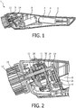
- the device 1 comprises a housing 2 having a first handheld region 4 which is suitable for being held by a user, and a second head region 5 configured to connect to a brush 3.
- the first region 4 encloses a battery 7.
- the battery 7 may be rechargeable. It should be appreciated that an alternative power source may be used, for example, the device may be connectable to a wall socket of the mains power supply.
- the battery 7 powers a drive means comprising an oscillation generator 26 and a rotational drive unit located in the second region 5.
- the oscillation generator 26 is configured to oscillate a shaft 14 disposed in the housing along its longitudinal axis and the rotational drive unit is configured to rotate the shaft 14 about its longitudinal axis.
- the housing 2 is further provided with an operating switch (not shown) for switching the device on/off and for switching the device into various oscillating and rotating operating modes as explained in more detail below.
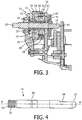
- the shaft 14 is configured to connect to the brush 3 and is disposed in the second region 5 of the housing 2. It is held and supported by a frame 11.
- the frame 11 is best illustrated in Figure 3 and it comprises first and second supports referred to as a front and a rear support 12, 13 that are spaced from one another so as to provide room for the oscillation generator 26.
- the shaft 14 is configured to rotate relative to the front and rear supports 12, 13 as will become apparent from the description below.
- the shaft 14 is shown in greater detail in Figure 4 , and it is generally shaped as a rod and has a longitudinal axis 'A'.
- the shaft 14 is preferably made out of stainless steel and comprises a ribbed end 15 which is formed with ridges 16 extending in the longitudinal direction 'A' of the shaft 14.
- the ribbed end 15 projects out of the second region 5 of the housing 2 where it connects to a corresponding recess 17 formed in the brush 3 (see Figure 2 ).
- the recess 17 of the brush 3 is formed of plastic and the brush is attached to the ribbed end 15 of the shaft 14 by press fit such that the plastic of the recess cold flows between the ridges 16.
- the ridges 16 of the ribbed end 15 improve the connection between the brush 3 and the shaft 14 as they mechanically interlock with the recess 17 of the brush 3 in a rotational direction about the longitudinal axis 'A' of the shaft 14. It should be understood that the present invention is not limited to a brush being connected to the housing, as any alternative skin treating part, such as a cotton pad or cushion, can be connected to the ribbed end which has a cleaning, exfoliating or massaging effect.
- a seal (not shown) is provided between the shaft 14 and the housing 2 proximal to the ribbed end 15 so as to form a water tight seal between said shaft 14 and housing 2.
- the shaft 14 On an opposite end 19 to the ribbed end 15, the shaft 14 is formed with a cut out portion 18 along the axial direction such that the cross-sectional profile of the shaft transverse to the longitudinal axis is 'D' shaped, as can be appreciated from Figure 4 .
- This end 19 locates in a corresponding centre of a gear 20 (see Figures 2 and 3 ) which forms part of the rotational drive unit
- the rotational drive unit comprises a motor 8 which is located in the housing 2 between the first and second regions 4, 5.
- the motor 8 has a motor shaft 9 as best seen in Figure 2 , the motor shaft 9 can be driven in two opposing rotational directions and at different rotational speeds.
- the rotational drive unit further comprises a train gear 21 which is connected to the motor shaft 9 of the motor 8. The rotating movement of the rotational drive unit is generated by the motor 8 which rotates the motor shaft 9.
- the motor shaft 9 in turn rotates the train gear 21 including the gear 20 which the shaft 14 is connected to such that shaft 14 itself rotates. This is not described in any great detail as it is considered to be common general knowledge of a skilled person. It shall be appreciated that the train gear may comprise one or a plurality of gears depending on the arrangement of the motor 8 and the shaft 14.
- the shaft 14 is held by the front and rear supports 12, 13 of the frame 11.
- the rear support 13 holds the shaft 14 in a region adjacent to the cut out portion 18 such that the shaft can rotate and move in an axial direction relative to said rear support 13.
- the shaft 14 is moveable in an axial direction relative to the gear 20 in which it locates.
- the front support 12 is formed with an e-clip 23 (see Figure 3 ) which locates in a circumferential groove 24 (see Figure 4 ) formed on the shaft proximate to the ribbed end 15 such that the shaft 14 can rotate but is prevented from moving in an axial direction relative to the front support 12.
- the front support is not formed with an e-clip and the front support is configured to locate directly in the circumferential groove 24.
- the front support 12 is flexibly connected to the frame 11 so as to allow for the shaft to move between a forward and a rearward position as the shaft oscillates along its longitudinal direction.
- a flux assembly 25 which forms part of the oscillation generator 26.
- the flux assembly 25 is formed on a bush 27 which surrounds the shaft 14. The bush 27 and the corresponding bearing surface of the shaft 14 enable the shaft 14 to rotate freely relative to the flux assembly 25.
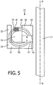
- the flux assembly 25 will now be described with reference to Figure 3 and 5 .
- the flux assembly comprises inner and outer flux concentrators 28, 29, preferably made out of a magnetically soft material such as a soft iron.
- the outer flux 29 concentrator is formed of a circular base panel 31 having a peripheral side panel 32.
- the inner flux concentrator 28 is shaped into a disc and although not illustrated, it should be understood that the inner flux concentrator 28 may also be formed with a peripheral side panel.
- the inner flux concentrator locates within the outer flux concentrator 29 and a concentric annular gap 34 is formed between a peripheral edge 35 of the inner flux concentrator and the peripheral side panel 32 of the outer flux concentrator 29.
- a space is also formed between a flat surface 36 of the inner flux concentrator 28 and the circular base panel 31 of the outer flux concentrator 29.
- Both the circular panel 31 of the outer flux concentrator 29 and the inner flux concentrator 28 are formed with a central hole (not shown) through which the shaft 14 extends.
- the flux assembly 25 further comprises a permanent magnet 37 located in the space formed between the flat surface 36 of the inner flux concentrator 28 and the circular base panel 31 of the outer flux concentrators 29.
- the magnet 37 is preferably made out of neodymium iron boron and is also disc shaped formed with a central hole (not shown) such that the shaft 14 can extend therethrough.
- the magnet 37 has a similar diameter to the inner flux concentrator 28 such that that the annular gap 34 extends also between the magnet 37 and the peripheral side panel 32 of the outer flux concentrators 29.
- the polarity of the magnet 37 is permanent and the north and south poles are represented by 'N' and 'S'.
- the magnetic field 38 emitted by the magnet 37 is illustrated by the lines 30.
- the magnetic field 38 is substantially radially orientated relative to the longitudinal axis 'A' of the shaft 14 around which the magnet 37 locates, and as the magnet 37 is sandwiched between the inner and outer flux concentrators 28, 29, the majority of the magnetic field 38 emitted by the magnet 37 is contained within the annular gap 34 such that a great magnetic force is generated.
- the oscillation generator 26 further comprises a solenoid 39 is attached to the rear support 13 and is locatable in the annular gap 34.
- the solenoid 39 comprises numerous turns of insulated conductor wire 40 and is arranged such that it is concentric with the magnet 37 and the flux concentrators 28, 29, however there is no contact between the solenoid 39 and the flux assembly 25.
- the solenoid 39 is made out of copper wire being 0.15mm in diameter, having a resistance of 10.2R and coiled for 220 turns.
- the solenoid 39 is electrically connected to the battery 7 via an inverter (not shown).
- the inverter converts direct current (dc) supplied by the battery 7 to alternating current (ac).
- the alternating current flowing through the coiled wire 39 produces a magnetic field having an alternating polarity that interacts with the permanent magnetic field of the magnet 37 sandwiched between the inner and outer flux concentrators 28, 29.
- the magnet 37 and the solenoid 39 are alternating between being attracted and repelled by one another.
- the inner and outer flux concentrators 28, 29 and the magnet 37 are mounted on the bush 27 such that the shaft 17 can freely rotate relative to them.
- This arrangement also enables the bush 27 and the flux assembly 25 to move in an axial direction 'A'.
- the solenoid 39 is attached to the rear support 13 and its polarity is alternating, the bush 27 and the flux assembly 25 is moving towards and away from the solenoid 39 along the shaft 14. This generates a vibrational or an oscillating motion that is transferred to the front support 12 via the e-clip 23 and the rear support 13 via stops 41 as will now be explained.
- the shaft 14 moves to a rearward position.
- the flux assembly oscillates or vibrates along the shaft 14 and impacts the e-clip 23 of the front support 12 and the stops 41 on the rear support 13 resulting in the shaft 14 oscillating or vibrating in an axial direction of its longitudinal axis 'A'.
- a spring (not shown), such as a curved spring disc, can be located at either or both ends of the outer flux concentrator 29 impacting the e-clip 23 and stops 41.
- the springs reduce the momentum of the flux assembly 25 however sufficient force is transferred to the e-clip 23 and stops 41 such that the shaft 14 moves between its forward and rearward positions.
- the springs are preferably made out of a non-metallic, age-hardening beryllium copper alloy with high strength.
- the nominal spring has a spring rate of 3.2N/mm and so the spring rate at 80Hz frequency is 2.8N/mm and the spring rate at 110Hz frequency is 5.3N/mm.
- the device 1 further comprises a frequency converter (not shown) which changes the frequency of the alternating current so that the resulting oscillation of the flux assembly 25 can be changed.
- the frequency converter is configured to convert the frequency between two modes; the first mode being 80Hz and the second mode being 110Hz. A higher frequency produces less audible noise than a lower frequency mode because the directional change of the flux assembly is faster which prevents the flux assembly from impacting the e-clip 23 and the stops 41 with such a high momentum compared to a lower frequency.
- the device 1 can be configured to operate at various modes.
- the operating switch might have eight settings corresponding to eight operating modes which are based on three rotational speeds; 0, 180 and 250 rpm, and three oscillating frequencies; 0, 80 and 110 Hz.
- the combinations of modes are listed in the table below.
- the device further comprises a controller (not shown) which is configured to control the different operating modes in response to a user input. For example, when a user switches the switch into a first setting so that the device is in its first operating mode, the controller operates the battery 7 so that it supplies current to the motor 8, and operates the motor 8 so that the shaft 14 and the brush 3 rotates at 180rpm. Simultaneously, the controller operates the battery 7 so that it supplies current to the oscillation generator 26. The controller further operates the inverter so to convert the direct current to an alternating current. The controller also sets the frequency converter to 80 Hz. As a result, the oscillation generator 26 also oscillates the shaft 14 and the brush 3 in the axial direction at 80 Hz.
- the controller switches off the supply of current from the battery 7 to the motor 8 but continues to operate the oscillation generator 26 such that the shaft 14 and brush 3 only move in the axial direction. If the user thereafter changes the operating mode to operating mode 6, then the controller operates the frequency converter so that it increases the frequency of the alternating current resulting in a stronger oscillation of the shaft 14.
- the device is not limited to these eight operating modes.
- the device may comprise more or fewer oscillating frequencies and/or rotational speeds, such that it comprises more or fewer operating modes.
- the device comprises two separate switches, a first switch for controlling the rotation of the shaft 14 and the brush 3 and a second switch for controlling the oscillation of the shaft 14 and the brush 3.
- the first switch may have four settings corresponding to four rotational speeds; 0, 180, 220 and 250 rpm, and the second switch may also have four setting corresponding to four oscillating frequencies; 0, 80, 100 and 110 Hz.
- the device is configured to have a total of 15 operating modes.
- the user can operate the two switches independently of one another so that they can obtain the desired combination of rotating and oscillating movement of the brush 3.
- the two separate switches are not limited to having four settings each, for example, each switch may be configured to have three settings each such that the device has a total of eight operating modes.
- the shaft 14 and also the brush 3 oscillate or move in a direction parallel to the longitudinal axis 'A' of the shaft 14.
- the brush 3 and the shaft 14 oscillate or move substantially perpendicular to the skin, which improves the cleaning and the massaging effect on the skin.
- the configuration of the device as described above enables the oscillating movement and rotating movement to be independently adjusted to the user's preference.
- the device 1 is not limited to comprising a brush 3, it may comprise an alternative skin treating part having a rough surface for exfoliating or a surface comprising massaging protrusions.
- the oscillating generator 26 is reversely configured such that the solenoid 39 is mounted on the front support 12 and the shaft 14 is formed with a groove in which the rear support 13 locates.
- both the front and the rear supports 12, 13 are flexibly connected to the frame 11 and the shaft 14 is formed with a second circumferential groove in which the rear frame 13 locates such that impact of the oscillation generator and the front and rear supports 12, 13 oscillate or move the shaft 14 in an axial direction between forward and rear positions.
- the inner and outer flux concentrators 28, 29, the permanent magnet 37 and the solenoid 39 are not limited to having a circular cross-section transverse to the longitudinal axis of the shaft.
- they can all have a square or a rectangular cross-section.
Landscapes
- Health & Medical Sciences (AREA)
- Animal Behavior & Ethology (AREA)
- Public Health (AREA)
- Physical Education & Sports Medicine (AREA)
- Rehabilitation Therapy (AREA)
- Life Sciences & Earth Sciences (AREA)
- Epidemiology (AREA)
- General Health & Medical Sciences (AREA)
- Pain & Pain Management (AREA)
- Veterinary Medicine (AREA)
- Dermatology (AREA)
- Percussion Or Vibration Massage (AREA)
- Massaging Devices (AREA)
- Surgical Instruments (AREA)
- Brushes (AREA)
Claims (13)
- Vorrichtung zur Behandlung von Haut, umfassend ein Gehäuse (2) eine Welle (14), die im Gehäuse (2) gelegen ist, mit einer Längsachse 'A' und einem Ende zum Aufnehmen eines Hautbehandlungsteils (3), und ein Antriebsmittel, das gestaltet ist, die Welle um ihre Längsachse in Drehung und in einer Richtung entlang der Längsachse in Schwingung zu versetzen, wobei die Antriebsmittel eine Drehantriebseinheit zum Drehen der Welle (14) und einen Schwingungserzeuger (26), um die Welle in Schwingung zu versetzen, umfassen, wobei der Schwingungserzeuger (26) eine Solenoid (39) und eine Flussanordnung (25) umfasst, dadurch gekennzeichnet, dass:
der Schwingungserzeuger (26) um die Welle (14) gelegen ist, sodass die Welle relativ zum Schwingungserzeuger (26) drehbar ist; und wobei die Flussanordnung (25) entlang der Welle (14) relativ zum Solenoid (39) bewegbar ist. - Vorrichtung nach Anspruch 1, wobei die Drehantriebseinheit und der Schwingungserzeuger (26) so gestaltet sind, dass die Drehzahl und die Frequenz der Schwingung der Welle (14) unabhängig voneinander in Reaktion auf eine Benutzereingabe geändert werden können.
- Vorrichtung nach Anspruch 1, wobei die Flussanordnung (25) einen inneren und einen äußeren Flusskonzentrator (28, 29) und einen Magneten (37), der dazwischen gelegen ist, umfassen.
- Vorrichtung nach Anspruch 3, wobei der äußere Flusskonzentrator (29) aus einer Grundplatte (31) mit einer peripheren Seitenplatte (32) besteht und der innere Flusskonzentrator (28) innerhalb der peripheren Seitenplatte (32) aufgenommen ist, wobei der Magnet (37) zwischen dem inneren Flusskonzentrator (28) und der Grundplatte (31) gelegen ist und ein Spalt (34) zwischen dem inneren Flusskonzentrator (28) und der peripheren Seitenplatte (32) gebildet ist, um den Solenoid (39) aufzunehmen.
- Vorrichtung nach Anspruch 1, wobei die Vorrichtung weiter erste und zweite Träger (12, 13) umfasst, die die Welle (14) halten, die Flussanordnung (25) um die Welle (14) zwischen dem ersten und zweiten Träger (12, 13) gelegen ist und der Solenoid (29) an einem der Träger (12, 13) befestigt ist.
- Vorrichtung nach Anspruch 5, wobei die Welle (14) durch den ersten und zweiten Träger (12, 13) so gehalten wird, dass die Welle (14) relativ zu den Trägern (12, 13) um die Längsachse drehbar ist, aber an einer Bewegung entlang der Längsachse relativ zu mindestens einem der Träger (12, 13) gehindert wird.
- Vorrichtung nach Anspruch 6, wobei die Welle (14) eine Umfangsrille (24) umfasst, in der einer der Träger (12) gelegen ist, um so eine Bewegung der Welle (14) entlang der Längsachse relativ zum Träger zu verhindern, der in der Rille (24) gelegen ist.
- Vorrichtung nach Anspruch 7, wobei einer der Träger (12, 13) mit einem E-Clip (23) gebildet ist, der in der Umfangsrille (24) gelegen ist.
- Vorrichtung nach einem der Ansprüche 5 bis 8, wobei einer der Träger (12, 13) mit einem Anschlag (41) gebildet ist, auf den die Flussanordnung (25) prallt, wenn sie schwingt.
- Vorrichtung nach einem der Ansprüche 5 bis 9, wobei eine Feder zwischen dem ersten oder dem zweiten Träger (12, 13) und der Flussanordnung (25) gelegen ist, um so den Aufprall zu verringern, wenn die Flussanordnung (25) schwingt.
- Vorrichtung nach einem der vorstehenden Ansprüche, wobei die Vorrichtung weiter eine Energiequelle (7) umfasst, die die Antriebsmittel mit Energie versorgt.
- Vorrichtung nach Anspruch 11, wobei die Vorrichtung weiter einen Wechselrichter zum Ändern des Stroms, der durch die Stromquelle (7) zugeleitet wird, in Wechselstrom umfasst.
- Vorrichtung nach Anspruch 12, wobei die Vorrichtung weiter einen Frequenzwandler zum Ändern der Frequenz des Wechselstroms umfasst.
Priority Applications (1)
| Application Number | Priority Date | Filing Date | Title |
|---|---|---|---|
| EP13732183.2A EP2872098B1 (de) | 2012-07-10 | 2013-06-28 | Hautbehandlungsvorrichtung |
Applications Claiming Priority (3)
| Application Number | Priority Date | Filing Date | Title |
|---|---|---|---|
| EP12175730 | 2012-07-10 | ||
| EP13732183.2A EP2872098B1 (de) | 2012-07-10 | 2013-06-28 | Hautbehandlungsvorrichtung |
| PCT/EP2013/063659 WO2014009177A1 (en) | 2012-07-10 | 2013-06-28 | A device for treating skin |
Publications (2)
| Publication Number | Publication Date |
|---|---|
| EP2872098A1 EP2872098A1 (de) | 2015-05-20 |
| EP2872098B1 true EP2872098B1 (de) | 2019-03-20 |
Family
ID=48700602
Family Applications (1)
| Application Number | Title | Priority Date | Filing Date |
|---|---|---|---|
| EP13732183.2A Active EP2872098B1 (de) | 2012-07-10 | 2013-06-28 | Hautbehandlungsvorrichtung |
Country Status (8)
| Country | Link |
|---|---|
| US (1) | US10143615B2 (de) |
| EP (1) | EP2872098B1 (de) |
| JP (1) | JP6335893B2 (de) |
| CN (2) | CN103536428B (de) |
| BR (1) | BR112015000326B1 (de) |
| RU (1) | RU2629234C2 (de) |
| TR (1) | TR201907293T4 (de) |
| WO (1) | WO2014009177A1 (de) |
Families Citing this family (24)
| Publication number | Priority date | Publication date | Assignee | Title |
|---|---|---|---|---|
| EP2872098B1 (de) * | 2012-07-10 | 2019-03-20 | Koninklijke Philips N.V. | Hautbehandlungsvorrichtung |
| KR101447049B1 (ko) * | 2013-08-07 | 2014-10-07 | 글로빅스주식회사 | 오토 클렌징 장치 |
| US10194935B2 (en) * | 2013-12-31 | 2019-02-05 | L'oreal | Shear-induced dermal infusion |
| KR101679794B1 (ko) * | 2014-02-04 | 2016-11-29 | (주)센트로닉스 | 왕복 회전 운동 장치 및 이를 포함하는 세정 장치 |
| WO2015169606A1 (en) * | 2014-05-06 | 2015-11-12 | Koninklijke Philips N.V. | Bodycare device |
| WO2016001048A1 (en) | 2014-06-30 | 2016-01-07 | Koninklijke Philips N.V. | A bodycare device |
| USD771389S1 (en) * | 2015-04-14 | 2016-11-15 | Starmoon Ltd. | Cosmetic brush |
| ITUB20155001A1 (it) * | 2015-11-06 | 2017-05-06 | Tenacta Group Spa | Dispositivo per la cura della pelle |
| RU2746952C2 (ru) * | 2015-12-18 | 2021-04-22 | Конинклейке Филипс Н.В. | Щетка с губчатым или пенистым элементом |
| US10022025B2 (en) * | 2016-05-20 | 2018-07-17 | Chirp Products, LLC | Dual motor cleansing brush |
| BR112018074597B1 (pt) | 2016-05-31 | 2023-03-21 | Koninklijke Philips N.V | Cabeça de tratamento de pele para um dispositivo para cuidados com o corpo, dispositivo para cuidados com o corpo para tratamento de pele, e kit de partes |
| EP3262976B1 (de) | 2016-06-30 | 2020-06-17 | M+C Schiffer GmbH | Bürste |
| EP3391793A1 (de) * | 2017-04-17 | 2018-10-24 | Koninklijke Philips N.V. | Körperpflegevorrichtung |
| CN106943292A (zh) * | 2017-04-26 | 2017-07-14 | 东莞市谦禾电子科技有限公司 | 洁面仪的工作方法 |
| US11241083B2 (en) | 2017-07-13 | 2022-02-08 | Chirp Products, LLC | Cleansing brush head |
| CN107582359A (zh) * | 2017-09-19 | 2018-01-16 | 蒋仁义 | 一种敲击按摩器 |
| EP3505031A1 (de) | 2017-12-28 | 2019-07-03 | Koninklijke Philips N.V. | Reinigung mit doppelter bewegung mit einem mechanischen einrastzubehör |
| CN108523968B (zh) * | 2018-02-26 | 2020-07-24 | 河北北方学院附属第一医院 | 一种皮肤科用病灶刮清器 |
| EP3649888A1 (de) | 2018-11-06 | 2020-05-13 | Koninklijke Philips N.V. | Hautbehandlungskopf mit integriertem auslösesystem |
| US11399624B2 (en) * | 2018-12-18 | 2022-08-02 | L'oreal | Skincare device having optimized dual energy modalities, and associated systems and methods |
| US11730668B2 (en) | 2020-06-29 | 2023-08-22 | Therabody, Inc. | Vibrating therapy system and device |
| US11413212B2 (en) * | 2019-01-30 | 2022-08-16 | L'oreal | Energy regenerating end effector, and associated systems and methods |
| US11564863B2 (en) | 2020-06-29 | 2023-01-31 | Therabody, Inc. | Cooling attachment module for facial treatment device |
| USD961153S1 (en) * | 2020-10-09 | 2022-08-16 | Parfums Christian Dior | Cosmetic applicator device |
Citations (1)
| Publication number | Priority date | Publication date | Assignee | Title |
|---|---|---|---|---|
| JP2009207537A (ja) * | 2008-02-29 | 2009-09-17 | Ya Man Ltd | 美容ブラシ器具 |
Family Cites Families (42)
| Publication number | Priority date | Publication date | Assignee | Title |
|---|---|---|---|---|
| US2234102A (en) * | 1937-04-26 | 1941-03-04 | Automatic Instr Company | Vibrator |
| US2378335A (en) * | 1943-11-01 | 1945-06-12 | Quality Hardware And Machine C | Massage device |
| US3096758A (en) * | 1962-06-28 | 1963-07-09 | Frederick T Savage | Vibrator |
| US3512201A (en) * | 1967-04-25 | 1970-05-19 | Theodore L Taylor | Power toothbrush |
| US3980908A (en) * | 1974-08-12 | 1976-09-14 | Mcclintock Richard D | Exposure control system |
| US4512339A (en) * | 1981-04-24 | 1985-04-23 | Mcshirley Products, Inc. | Percussor application |
| US4549535A (en) * | 1982-12-06 | 1985-10-29 | Wing Thomas W | Linear motor massage apparatus |
| US4841955A (en) * | 1987-05-21 | 1989-06-27 | Kinetic Technology, Inc. | Chiropractic adjustor |
| JP2694694B2 (ja) * | 1988-02-18 | 1997-12-24 | ライナー マリア株式会社 | バイブレータ |
| JPH03218763A (ja) * | 1988-12-12 | 1991-09-26 | Shinatsushin Kurinitsuku:Kk | マッサージ器 |
| US5208933A (en) | 1990-11-09 | 1993-05-11 | L. Paul Lustig | Dental tool with liquid dispensing, and cartridge |
| CN2138494Y (zh) * | 1991-12-19 | 1993-07-21 | 上海英特电器厂 | 捶击式按摩软靠垫 |
| US5593381A (en) * | 1994-07-25 | 1997-01-14 | Neptune Pundak & Ayalon Ltd. | Skin and tissue treatment and stimulation device and method |
| US5423102A (en) | 1994-08-19 | 1995-06-13 | Madison; Ava | Portable cleaning device |
| DE19505047C1 (de) * | 1995-02-15 | 1997-01-09 | Gemicon Gmbh | Therapiegerät |
| CN2282869Y (zh) | 1996-09-23 | 1998-06-03 | 李飞 | 电控转动及直动按摩保健器 |
| US6277085B1 (en) * | 1998-06-09 | 2001-08-21 | Michael P. Flynn | Solenoidal skin vibrator energized by complex electric waveforms |
| US20020156402A1 (en) * | 1998-06-16 | 2002-10-24 | Philippe-Guy E. Woog | Sonic therapeutic machine for the body |
| US6805700B2 (en) * | 2002-04-12 | 2004-10-19 | Edward W. Miller | Percussive therapeutic device |
| WO2003096860A1 (en) | 2002-05-21 | 2003-11-27 | Koninklijke Philips Electronics N.V. | Apparatus for treating a person's skin |
| US6722232B1 (en) * | 2002-08-01 | 2004-04-20 | Crt Enterprises, Inc. | Manually-powered drive device and assembly |
| RU2346709C2 (ru) * | 2003-06-13 | 2009-02-20 | Панасоник Электрик Уорк Ко., Лтд. | Устройство для ухода за кожей с использованием сонофореза |
| EP1633439B1 (de) * | 2003-06-13 | 2006-12-13 | Matsushita Electric Works, Ltd. | Hautbehandlungsgerät mittels ultraschall |
| JP4075001B2 (ja) * | 2003-06-17 | 2008-04-16 | ドクタース テック カンパニー リミティッド | 皮膚美容装置 |
| US20060122631A1 (en) | 2003-07-14 | 2006-06-08 | Kertz M G | Skin Cleaner |
| KR100491094B1 (ko) * | 2004-06-28 | 2005-05-24 | 김방배 | 자기 갭 방식의 수직 운동기 |
| US7921496B2 (en) * | 2004-07-09 | 2011-04-12 | Joo A Choi | Electric toothbrush |
| US8083699B2 (en) | 2004-08-26 | 2011-12-27 | Neuromechanical Innovations, Llc | Electromechanical adjusting instrument |
| JP4561321B2 (ja) * | 2004-11-09 | 2010-10-13 | サンケン電気株式会社 | ソレノイド駆動装置 |
| US6994679B1 (en) * | 2005-02-10 | 2006-02-07 | Kun-Ta Lee | Message device |
| US7654271B2 (en) * | 2005-06-02 | 2010-02-02 | The Procter & Gamble Company | Cosmetic applicator |
| US7762269B2 (en) * | 2005-06-02 | 2010-07-27 | The Procter & Gamble Company | Cosmetic applicator |
| US20070112357A1 (en) | 2005-06-21 | 2007-05-17 | Jack Skinner | Utilizing vibrational energy under 1000 hertz for dermatological infusion treatment modality |
| US20080036303A1 (en) * | 2006-06-15 | 2008-02-14 | Clive Graham Stevens | Linear motor for imparting vibration to a supported body |
| RU2009142414A (ru) | 2007-04-18 | 2011-05-27 | Конинклейке Филипс Электроникс Н.В. (Nl) | Электромеханическое массажное устройство и носимое массажное устройство |
| US8096963B2 (en) * | 2007-08-08 | 2012-01-17 | Muthu Murugan | Electromagnetic device, method and apparatus for selective application to vertebrates |
| CN101990408A (zh) | 2008-04-08 | 2011-03-23 | 欧莱雅 | 振动涂敷器 |
| KR200451858Y1 (ko) * | 2008-06-30 | 2011-01-17 | (주)아모레퍼시픽 | 피부 맛사지기 |
| JP2010075264A (ja) | 2008-09-24 | 2010-04-08 | Tadashi Adachi | マッサージ器 |
| US20110166486A1 (en) * | 2009-05-01 | 2011-07-07 | Norio Kumanomido | Compact and light weight portable transducer massager |
| US9125786B2 (en) * | 2011-03-31 | 2015-09-08 | Phillip Anthony FEMANO | Method and device to alleviate carpal tunnel syndrome and dysfunctions of other soft tissues |
| EP2872098B1 (de) | 2012-07-10 | 2019-03-20 | Koninklijke Philips N.V. | Hautbehandlungsvorrichtung |
-
2013
- 2013-06-28 EP EP13732183.2A patent/EP2872098B1/de active Active
- 2013-06-28 RU RU2015104176A patent/RU2629234C2/ru active
- 2013-06-28 US US14/413,031 patent/US10143615B2/en not_active Expired - Fee Related
- 2013-06-28 BR BR112015000326-5A patent/BR112015000326B1/pt not_active IP Right Cessation
- 2013-06-28 TR TR2019/07293T patent/TR201907293T4/tr unknown
- 2013-06-28 WO PCT/EP2013/063659 patent/WO2014009177A1/en not_active Ceased
- 2013-06-28 JP JP2015520894A patent/JP6335893B2/ja not_active Expired - Fee Related
- 2013-07-09 CN CN201310291968.XA patent/CN103536428B/zh active Active
- 2013-07-09 CN CN201320410286.1U patent/CN203634446U/zh not_active Expired - Lifetime
Patent Citations (1)
| Publication number | Priority date | Publication date | Assignee | Title |
|---|---|---|---|---|
| JP2009207537A (ja) * | 2008-02-29 | 2009-09-17 | Ya Man Ltd | 美容ブラシ器具 |
Also Published As
| Publication number | Publication date |
|---|---|
| BR112015000326A2 (pt) | 2017-06-27 |
| RU2629234C2 (ru) | 2017-08-28 |
| CN103536428A (zh) | 2014-01-29 |
| BR112015000326B1 (pt) | 2021-05-04 |
| EP2872098A1 (de) | 2015-05-20 |
| CN203634446U (zh) | 2014-06-11 |
| TR201907293T4 (tr) | 2019-06-21 |
| CN103536428B (zh) | 2017-10-13 |
| JP6335893B2 (ja) | 2018-05-30 |
| WO2014009177A1 (en) | 2014-01-16 |
| US10143615B2 (en) | 2018-12-04 |
| JP2015522353A (ja) | 2015-08-06 |
| RU2015104176A (ru) | 2016-08-27 |
| US20150202114A1 (en) | 2015-07-23 |
Similar Documents
| Publication | Publication Date | Title |
|---|---|---|
| EP2872098B1 (de) | Hautbehandlungsvorrichtung | |
| JP5745509B2 (ja) | 個人用皮膚手入れ器具のためのモータ | |
| JP7041622B6 (ja) | スポンジ又は発泡体要素を備えたブラシ | |
| CN202568836U (zh) | 电动穴位按摩仪 | |
| JP2007330790A (ja) | 線型のモータを具えた線型のモータを具えた振動トレーニング装置 | |
| CN112294624A (zh) | 成人刺激装置 | |
| US20090221944A1 (en) | Hand Held Massaging Tool | |
| JP5570385B2 (ja) | マッサージローラー | |
| WO2008129587B1 (en) | Medical apparatus with magnetotherapy function in combination with massaging and/or vibrating function | |
| EP3463245B1 (de) | Schälkopf mit wälzkörpern | |
| RU2343897C2 (ru) | Прибор для ножных процедур | |
| CN201161064Y (zh) | 一种带有旋转磁盘的磁疗按摩椅 | |
| KR200480606Y1 (ko) | 안마용 진동의자 | |
| KR101144174B1 (ko) | 믹서기용 비엘디씨 모터 | |
| CN202218972U (zh) | 一种磁力推动按摩轮的足部按摩装置 | |
| KR20090065779A (ko) | 디지털 복합운동 전동칫솔 | |
| CN106963509B (zh) | 一种扭转式电动牙刷的驱动机构 | |
| CN2074705U (zh) | 袖珍电动按摩磁疗剃须器 | |
| CN207490733U (zh) | 智能电机 | |
| CN121667587A (zh) | 一种高速清扫装置 | |
| CN107659110A (zh) | 智能电机 | |
| US20150171724A1 (en) | Device with magnetic coupler and electric tool assembly having such a device | |
| CN110916341A (zh) | 一种洁面仪 | |
| HK1179425B (en) | Motor for a personal skin care appliance | |
| JP2007222552A (ja) | マッサージ機 |
Legal Events
| Date | Code | Title | Description |
|---|---|---|---|
| PUAI | Public reference made under article 153(3) epc to a published international application that has entered the european phase |
Free format text: ORIGINAL CODE: 0009012 |
|
| 17P | Request for examination filed |
Effective date: 20150210 |
|
| AK | Designated contracting states |
Kind code of ref document: A1 Designated state(s): AL AT BE BG CH CY CZ DE DK EE ES FI FR GB GR HR HU IE IS IT LI LT LU LV MC MK MT NL NO PL PT RO RS SE SI SK SM TR |
|
| AX | Request for extension of the european patent |
Extension state: BA ME |
|
| DAX | Request for extension of the european patent (deleted) | ||
| 17Q | First examination report despatched |
Effective date: 20160329 |
|
| GRAP | Despatch of communication of intention to grant a patent |
Free format text: ORIGINAL CODE: EPIDOSNIGR1 |
|
| STAA | Information on the status of an ep patent application or granted ep patent |
Free format text: STATUS: GRANT OF PATENT IS INTENDED |
|
| INTG | Intention to grant announced |
Effective date: 20181019 |
|
| RIN1 | Information on inventor provided before grant (corrected) |
Inventor name: MARK, ROB Inventor name: PARDOEL, MICHEL, GERARDUS Inventor name: CAPRIHAN, ARJUN Inventor name: SKEATS, ANTHONY, JAMES Inventor name: YEAP, CHIN ENG |
|
| GRAS | Grant fee paid |
Free format text: ORIGINAL CODE: EPIDOSNIGR3 |
|
| GRAA | (expected) grant |
Free format text: ORIGINAL CODE: 0009210 |
|
| STAA | Information on the status of an ep patent application or granted ep patent |
Free format text: STATUS: THE PATENT HAS BEEN GRANTED |
|
| AK | Designated contracting states |
Kind code of ref document: B1 Designated state(s): AL AT BE BG CH CY CZ DE DK EE ES FI FR GB GR HR HU IE IS IT LI LT LU LV MC MK MT NL NO PL PT RO RS SE SI SK SM TR |
|
| REG | Reference to a national code |
Ref country code: GB Ref legal event code: FG4D |
|
| REG | Reference to a national code |
Ref country code: CH Ref legal event code: EP |
|
| REG | Reference to a national code |
Ref country code: DE Ref legal event code: R096 Ref document number: 602013052594 Country of ref document: DE |
|
| REG | Reference to a national code |
Ref country code: AT Ref legal event code: REF Ref document number: 1109751 Country of ref document: AT Kind code of ref document: T Effective date: 20190415 |
|
| REG | Reference to a national code |
Ref country code: IE Ref legal event code: FG4D |
|
| REG | Reference to a national code |
Ref country code: NL Ref legal event code: MP Effective date: 20190320 |
|
| PG25 | Lapsed in a contracting state [announced via postgrant information from national office to epo] |
Ref country code: LT Free format text: LAPSE BECAUSE OF FAILURE TO SUBMIT A TRANSLATION OF THE DESCRIPTION OR TO PAY THE FEE WITHIN THE PRESCRIBED TIME-LIMIT Effective date: 20190320 Ref country code: SE Free format text: LAPSE BECAUSE OF FAILURE TO SUBMIT A TRANSLATION OF THE DESCRIPTION OR TO PAY THE FEE WITHIN THE PRESCRIBED TIME-LIMIT Effective date: 20190320 Ref country code: NO Free format text: LAPSE BECAUSE OF FAILURE TO SUBMIT A TRANSLATION OF THE DESCRIPTION OR TO PAY THE FEE WITHIN THE PRESCRIBED TIME-LIMIT Effective date: 20190620 Ref country code: FI Free format text: LAPSE BECAUSE OF FAILURE TO SUBMIT A TRANSLATION OF THE DESCRIPTION OR TO PAY THE FEE WITHIN THE PRESCRIBED TIME-LIMIT Effective date: 20190320 |
|
| REG | Reference to a national code |
Ref country code: LT Ref legal event code: MG4D |
|
| PG25 | Lapsed in a contracting state [announced via postgrant information from national office to epo] |
Ref country code: NL Free format text: LAPSE BECAUSE OF FAILURE TO SUBMIT A TRANSLATION OF THE DESCRIPTION OR TO PAY THE FEE WITHIN THE PRESCRIBED TIME-LIMIT Effective date: 20190320 Ref country code: LV Free format text: LAPSE BECAUSE OF FAILURE TO SUBMIT A TRANSLATION OF THE DESCRIPTION OR TO PAY THE FEE WITHIN THE PRESCRIBED TIME-LIMIT Effective date: 20190320 Ref country code: HR Free format text: LAPSE BECAUSE OF FAILURE TO SUBMIT A TRANSLATION OF THE DESCRIPTION OR TO PAY THE FEE WITHIN THE PRESCRIBED TIME-LIMIT Effective date: 20190320 Ref country code: RS Free format text: LAPSE BECAUSE OF FAILURE TO SUBMIT A TRANSLATION OF THE DESCRIPTION OR TO PAY THE FEE WITHIN THE PRESCRIBED TIME-LIMIT Effective date: 20190320 Ref country code: BG Free format text: LAPSE BECAUSE OF FAILURE TO SUBMIT A TRANSLATION OF THE DESCRIPTION OR TO PAY THE FEE WITHIN THE PRESCRIBED TIME-LIMIT Effective date: 20190620 Ref country code: GR Free format text: LAPSE BECAUSE OF FAILURE TO SUBMIT A TRANSLATION OF THE DESCRIPTION OR TO PAY THE FEE WITHIN THE PRESCRIBED TIME-LIMIT Effective date: 20190621 |
|
| REG | Reference to a national code |
Ref country code: AT Ref legal event code: MK05 Ref document number: 1109751 Country of ref document: AT Kind code of ref document: T Effective date: 20190320 |
|
| PG25 | Lapsed in a contracting state [announced via postgrant information from national office to epo] |
Ref country code: ES Free format text: LAPSE BECAUSE OF FAILURE TO SUBMIT A TRANSLATION OF THE DESCRIPTION OR TO PAY THE FEE WITHIN THE PRESCRIBED TIME-LIMIT Effective date: 20190320 Ref country code: PT Free format text: LAPSE BECAUSE OF FAILURE TO SUBMIT A TRANSLATION OF THE DESCRIPTION OR TO PAY THE FEE WITHIN THE PRESCRIBED TIME-LIMIT Effective date: 20190720 Ref country code: SK Free format text: LAPSE BECAUSE OF FAILURE TO SUBMIT A TRANSLATION OF THE DESCRIPTION OR TO PAY THE FEE WITHIN THE PRESCRIBED TIME-LIMIT Effective date: 20190320 Ref country code: RO Free format text: LAPSE BECAUSE OF FAILURE TO SUBMIT A TRANSLATION OF THE DESCRIPTION OR TO PAY THE FEE WITHIN THE PRESCRIBED TIME-LIMIT Effective date: 20190320 Ref country code: AL Free format text: LAPSE BECAUSE OF FAILURE TO SUBMIT A TRANSLATION OF THE DESCRIPTION OR TO PAY THE FEE WITHIN THE PRESCRIBED TIME-LIMIT Effective date: 20190320 Ref country code: CZ Free format text: LAPSE BECAUSE OF FAILURE TO SUBMIT A TRANSLATION OF THE DESCRIPTION OR TO PAY THE FEE WITHIN THE PRESCRIBED TIME-LIMIT Effective date: 20190320 Ref country code: IT Free format text: LAPSE BECAUSE OF FAILURE TO SUBMIT A TRANSLATION OF THE DESCRIPTION OR TO PAY THE FEE WITHIN THE PRESCRIBED TIME-LIMIT Effective date: 20190320 Ref country code: EE Free format text: LAPSE BECAUSE OF FAILURE TO SUBMIT A TRANSLATION OF THE DESCRIPTION OR TO PAY THE FEE WITHIN THE PRESCRIBED TIME-LIMIT Effective date: 20190320 |
|
| PG25 | Lapsed in a contracting state [announced via postgrant information from national office to epo] |
Ref country code: SM Free format text: LAPSE BECAUSE OF FAILURE TO SUBMIT A TRANSLATION OF THE DESCRIPTION OR TO PAY THE FEE WITHIN THE PRESCRIBED TIME-LIMIT Effective date: 20190320 Ref country code: PL Free format text: LAPSE BECAUSE OF FAILURE TO SUBMIT A TRANSLATION OF THE DESCRIPTION OR TO PAY THE FEE WITHIN THE PRESCRIBED TIME-LIMIT Effective date: 20190320 |
|
| PG25 | Lapsed in a contracting state [announced via postgrant information from national office to epo] |
Ref country code: IS Free format text: LAPSE BECAUSE OF FAILURE TO SUBMIT A TRANSLATION OF THE DESCRIPTION OR TO PAY THE FEE WITHIN THE PRESCRIBED TIME-LIMIT Effective date: 20190720 Ref country code: AT Free format text: LAPSE BECAUSE OF FAILURE TO SUBMIT A TRANSLATION OF THE DESCRIPTION OR TO PAY THE FEE WITHIN THE PRESCRIBED TIME-LIMIT Effective date: 20190320 |
|
| REG | Reference to a national code |
Ref country code: DE Ref legal event code: R097 Ref document number: 602013052594 Country of ref document: DE |
|
| PLBE | No opposition filed within time limit |
Free format text: ORIGINAL CODE: 0009261 |
|
| STAA | Information on the status of an ep patent application or granted ep patent |
Free format text: STATUS: NO OPPOSITION FILED WITHIN TIME LIMIT |
|
| PG25 | Lapsed in a contracting state [announced via postgrant information from national office to epo] |
Ref country code: DK Free format text: LAPSE BECAUSE OF FAILURE TO SUBMIT A TRANSLATION OF THE DESCRIPTION OR TO PAY THE FEE WITHIN THE PRESCRIBED TIME-LIMIT Effective date: 20190320 Ref country code: MC Free format text: LAPSE BECAUSE OF FAILURE TO SUBMIT A TRANSLATION OF THE DESCRIPTION OR TO PAY THE FEE WITHIN THE PRESCRIBED TIME-LIMIT Effective date: 20190320 |
|
| REG | Reference to a national code |
Ref country code: CH Ref legal event code: PL |
|
| 26N | No opposition filed |
Effective date: 20200102 |
|
| PG25 | Lapsed in a contracting state [announced via postgrant information from national office to epo] |
Ref country code: SI Free format text: LAPSE BECAUSE OF FAILURE TO SUBMIT A TRANSLATION OF THE DESCRIPTION OR TO PAY THE FEE WITHIN THE PRESCRIBED TIME-LIMIT Effective date: 20190320 |
|
| REG | Reference to a national code |
Ref country code: BE Ref legal event code: MM Effective date: 20190630 |
|
| PG25 | Lapsed in a contracting state [announced via postgrant information from national office to epo] |
Ref country code: IE Free format text: LAPSE BECAUSE OF NON-PAYMENT OF DUE FEES Effective date: 20190628 |
|
| PG25 | Lapsed in a contracting state [announced via postgrant information from national office to epo] |
Ref country code: CH Free format text: LAPSE BECAUSE OF NON-PAYMENT OF DUE FEES Effective date: 20190630 Ref country code: LU Free format text: LAPSE BECAUSE OF NON-PAYMENT OF DUE FEES Effective date: 20190628 Ref country code: LI Free format text: LAPSE BECAUSE OF NON-PAYMENT OF DUE FEES Effective date: 20190630 Ref country code: BE Free format text: LAPSE BECAUSE OF NON-PAYMENT OF DUE FEES Effective date: 20190630 |
|
| PG25 | Lapsed in a contracting state [announced via postgrant information from national office to epo] |
Ref country code: CY Free format text: LAPSE BECAUSE OF FAILURE TO SUBMIT A TRANSLATION OF THE DESCRIPTION OR TO PAY THE FEE WITHIN THE PRESCRIBED TIME-LIMIT Effective date: 20190320 |
|
| PG25 | Lapsed in a contracting state [announced via postgrant information from national office to epo] |
Ref country code: MT Free format text: LAPSE BECAUSE OF FAILURE TO SUBMIT A TRANSLATION OF THE DESCRIPTION OR TO PAY THE FEE WITHIN THE PRESCRIBED TIME-LIMIT Effective date: 20190320 Ref country code: HU Free format text: LAPSE BECAUSE OF FAILURE TO SUBMIT A TRANSLATION OF THE DESCRIPTION OR TO PAY THE FEE WITHIN THE PRESCRIBED TIME-LIMIT; INVALID AB INITIO Effective date: 20130628 |
|
| PGFP | Annual fee paid to national office [announced via postgrant information from national office to epo] |
Ref country code: TR Payment date: 20210616 Year of fee payment: 9 |
|
| PG25 | Lapsed in a contracting state [announced via postgrant information from national office to epo] |
Ref country code: MK Free format text: LAPSE BECAUSE OF FAILURE TO SUBMIT A TRANSLATION OF THE DESCRIPTION OR TO PAY THE FEE WITHIN THE PRESCRIBED TIME-LIMIT Effective date: 20190320 |
|
| PG25 | Lapsed in a contracting state [announced via postgrant information from national office to epo] |
Ref country code: TR Free format text: LAPSE BECAUSE OF NON-PAYMENT OF DUE FEES Effective date: 20220628 |
|
| PGFP | Annual fee paid to national office [announced via postgrant information from national office to epo] |
Ref country code: DE Payment date: 20250626 Year of fee payment: 13 |
|
| PGFP | Annual fee paid to national office [announced via postgrant information from national office to epo] |
Ref country code: GB Payment date: 20250617 Year of fee payment: 13 |
|
| PGFP | Annual fee paid to national office [announced via postgrant information from national office to epo] |
Ref country code: FR Payment date: 20250624 Year of fee payment: 13 |