EP2871981B1 - Dispositif de remplissage de tubes à cigarette - Google Patents
Dispositif de remplissage de tubes à cigarette Download PDFInfo
- Publication number
- EP2871981B1 EP2871981B1 EP13734434.7A EP13734434A EP2871981B1 EP 2871981 B1 EP2871981 B1 EP 2871981B1 EP 13734434 A EP13734434 A EP 13734434A EP 2871981 B1 EP2871981 B1 EP 2871981B1
- Authority
- EP
- European Patent Office
- Prior art keywords
- tobacco
- length
- stop
- slide
- chamber
- Prior art date
- Legal status (The legal status is an assumption and is not a legal conclusion. Google has not performed a legal analysis and makes no representation as to the accuracy of the status listed.)
- Active
Links
Images


Classifications
-
- A—HUMAN NECESSITIES
- A24—TOBACCO; CIGARS; CIGARETTES; SIMULATED SMOKING DEVICES; SMOKERS' REQUISITES
- A24C—MACHINES FOR MAKING CIGARS OR CIGARETTES
- A24C5/00—Making cigarettes; Making tipping materials for, or attaching filters or mouthpieces to, cigars or cigarettes
- A24C5/40—Hand-driven apparatus for making cigarettes
- A24C5/42—Pocket cigarette-fillers
- A24C5/425—Pocket cigarette-fillers for obtaining cigarettes of various lengths
-
- A—HUMAN NECESSITIES
- A24—TOBACCO; CIGARS; CIGARETTES; SIMULATED SMOKING DEVICES; SMOKERS' REQUISITES
- A24C—MACHINES FOR MAKING CIGARS OR CIGARETTES
- A24C5/00—Making cigarettes; Making tipping materials for, or attaching filters or mouthpieces to, cigars or cigarettes
- A24C5/40—Hand-driven apparatus for making cigarettes
- A24C5/42—Pocket cigarette-fillers
Definitions
- the invention relates to a device for stuffing prefabricated cigarette tubes, with a housing, a tobacco chamber, a tobacco associated therewith, a movable pressing bar for forming tobacco inserted into the tobacco chamber into a strand, a tobacco support associated abutment for one end of the tobacco rod, and a for filling the cigarette tubes with the tobacco rod relative to the housing displaceable slider.
- Such a device is known from DE 41 10 830 C1 known.
- the abutment is designed as an adjustable longitudinal direction of the tobacco part, provided according to the number of cigarette tubes of different length to be stuffed at least two predetermined locking positions are.
- Another generic device is from the DE 20 2008 012 816 U1 known.
- the tobacco support is displaceable relative to the abutment displaced by a distance in the direction of movement of the slider, which corresponds approximately to the length difference of the different Greraum lengths.
- a distance in the direction of movement of the slider corresponds approximately to the length difference of the different Greraum lengths.
- displaceable in the direction of movement of the slider arrangement of the tobacco support this moves automatically into a position corresponding to the available length of the tobacco when acting in the displacement direction, a force exceeding the adhesion of the tobacco support in the housing. This is the case regularly when the end of the tobacco support facing away from the abutment comes into contact with the filter of a filter sleeve.
- the pressing beam has a fixed part and a pressing member that optionally complements the movable part.
- an insert which can be inserted into the tobacco chamber, optionally on the abutment-side end, is provided. This is so dimensioned that it not only adapts the length of the tobacco chamber to the filling space length of the cigarette tube in the state inserted into the tobacco chamber, but the insert also forms a stop for the wall of the slider carrying a sleeve for holding the cigarette tube, so that Also, the maximum displacement is adapted to the respective filling space length of the cigarette tube.
- Another device for stuffing pre-made cigarette tubes comprises a housing and a slide displaceable relative to the housing for filling the cigarette tubes with the tobacco rod.
- the housing has a stop in association with the ejection slide of the shape that the ejection slide can be moved back far different to the filling of a tobacco press chamber with tobacco.
- the invention is therefore based on the object to provide an improved device for stuffing prefabricated cigarette tubes.
- a selectively attachable to the slider, provided in the attached state, the displacement path relative to the housing by a certain length shortening stop By attaching the stop, the displacement path is shortened by about a length by which the length of the filling space of a first cigarette tube differs from the longer filling space of another cigarette tube.
- the cigarette tube having the shorter filling space length may be a sleeve having a prolonged and / or filter portion supplemented by an activated carbon region so as to reduce the pollutant content inhaled when smoking a cigarette comprising a prefabricated filter sleeve.
- the stop on the slide is optionally attachable, it can be easily assemble or disassemble, because the slide is in contrast, for example, easily accessible to the tobacco receiving chamber and offers a relative to the tobacco receiving chamber considerably larger mounting space, so that the stop considerably larger and thus easier operable as an insertable example, in the tobacco receiving chamber stop can be formed.
- the abutment is then designed such that it protrudes when attached stop by the same length in the tobacco chamber. In this way it is achieved that the length of the tobacco receiving chamber is adapted in a corresponding manner to the filling space length of the cigarette tube with the shorter filling space as the displacement path.
- a spout with a free, preferably bevelled end is provided at an end portion of the slider, the outer diameter approximately the inner diameter of a cigarette tube corresponds.
- it is first pushed onto the spout, preferably by pressing down a cover provided on the slide, on which the pressing beam is provided, held stationary to the spout and finally pulled over by relocating the slider over the tobacco support, whereby the tobacco rod located thereon is displaced into the filling space of the cigarette paper tube.
- the stop is formed in a particularly preferred embodiment of the device according to the invention as a separate component of an effective length, which is selectively attachable to a remote from the spout wall of the slider.
- This separate component can for example be attached to a sales unit for the device according to the invention and be mounted by the user latter in the simplest manner, he would like to fill with the device cigarette tubes with shorter Greraum-length.
- the device according to the invention makes it suitable in a particularly simple manner for filling three different cigarette tubes which differ in their filling space lengths, in that the sales unit has two optionally mountable stops which differ in their length. be attached. Accordingly, a suitability for filling four different cigarette tubes by adding three different stops, for five different cigarette tubes by four stops, etc. possible.
- the abutment is - particularly preferably - formed by a provided in the tobacco receiving space insert whose length corresponds at least to the effective length of the longest stop provided.
- effective length is meant the length by which the displacement travel of the slider is shortened by activating the longest stop.
- the insert In order to shorten the displacement path, the insert, the cross-section of which preferably corresponds to the cross-section of a tobacco rod produced with the device, projects into the tobacco receiving chamber when the slider is in its end position limited by the stop, in which the tobacco receiving chamber with tobacco is in use is filled.
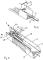
- the exemplary embodiment of a device according to the invention denoted by 100 in the drawing as a whole comprises a housing 1 with a base part 2, in which side recessed grips 3, 4 are incorporated.
- the base part is made of plastic.
- a slider 8 is guided in a straight line in the direction of movement S between the inner side walls 5, 6 and the bottom wall 7 thereof.
- the slider 8 on both sides of projections 9, which engage in complementary grooves 10 in the side walls 5, 6.
- a spout 11 is provided on the slide 8, whose outer diameter is adapted to the inner diameter of a prefabricated cigarette tube Z, that it can be pushed onto the spout 11 without much game.
- the free end of the spout 11 is laterally bevelled.
- the grommet 11 is integrally formed on its side inclined to the free end end portion of a retaining plate 12. To attach the spout 11 to the slide 13 grooves 14 are incorporated in the front wall, in which the holding plate 12 with its lateral edges from above can be inserted.
- a cover 15 is hinged to the slide 8 about a horizontal, perpendicular to the direction of movement S axis X a lid.
- the slider has an elongated recess 16 in the direction of movement S, which forms a tobacco chamber 17 and extends completely through the slider 8 in the vertical direction V.
- the bottom of the tobacco chamber 17 forms a trough-shaped tobacco support 18, which abuts the side almost of the side walls of the recess 16 and the lateral edges of longitudinal projections 19 of the tobacco chamber 17 covers so as to avoid tobacco getting between the lateral edges of the tobacco pad and the walls of the recess 16.
- the tobacco support 18 is made of a dimensionally stable material, such as metal and secured in the rear, protruding from the tobacco chamber 17 area on a arranged on the bottom wall 7 base on the base. Between the underside of the tobacco support 18 and the bottom wall 7 there is sufficient clearance that the tobacco support 18 when moving the slider 8 can penetrate unhindered through the spout 10 back (as in particular Fig. 7 shows).
- a pressing beam 21 is formed, the downwardly facing side 22 of which is in the closed state approximately hollow with the same radius as the tobacco support 18.
- the pressing beam 21 is further positioned so that it coincides with the side walls of the recess 16 under the tobacco support 18 in the closed state upwards such that the tobacco chamber has an approximately circular shape in cross section.
- a handle 23 which can be displaced towards the rear against an elastic force is attached to the lid 15. It has two extensions 24 which engage in against the elastic force to the rear displaced state of the handle in complementary recesses 25 of the slider 8. By the engagement of the extensions 24 in the recesses 25, the lid is locked against folding about the axis X.
- the tobacco chamber 17 is loosely filled with tobacco when the lid 15 is open. Subsequently, the open end of a prefabricated cigarette tube Z is pushed onto the spout 11 and the lid 15 is closed by pivoting about the axis X.
- the cigarette tube Z is held in position on the spout 11 by a pressing block 26 provided on the front portion of the lid 15 pushing the sleeve material against the spout 11 over part of the circumference. In the closed position of the lid 15, this is by actuation of the handle 23 and engagement the extensions 24 locked in the recesses 25.
- the lid 15 is displaced together with the slider 8 to the rear, wherein the cigarette tube Z pulled over the tobacco pad 18 and the tobacco held by a rear end of the tobacco chamber 18 forming abutment 27 and thus the cigarette tube Z over the located in the tobacco chamber 17 Tobacco rod is pulled.
- a stop 29 is provided, which is optionally on a wall 28, the wall 13, which carries the spout 11, opposite, mountable (see in particular FIGS. 5 and 6 ).
- the stop 29 can be pushed from the open bottom of the slide 8 on the wall 28.
- the stop in cross-section is approximately like a flattened in the vertical direction " ⁇ " formed.
- Between its foot 31 and its head 32 are located facing each other from slots 33 whose width is slightly smaller than the thickness of the wall 28 is formed.
- a recess 34 is incorporated centrally, which is slightly wider than the width of the bridge 35, which connects the foot 31 with the head 32 is.
- the stop 29 In its mounted position ( Fig. 5 ), the stop 29 is held by a clamping fit due to the engagement of the wall 28 in the slots 33 on both sides of the recess 34.
- the projection 29 reduces the maximum displacement path of the slider 8 in the displacement direction S relative to the base part 2 by the effective length D, which corresponds to the distance between the top of the foot 31 and the head 33.
- the abutment 27 has a length L, which corresponds to the effective length D of the stopper 29 (see Fig. 6 and 7 ).
- the abutment 27 through an insert 36, for example made of plastic, whose cross section corresponds approximately to the cross section of the tobacco rod to be introduced into the sleeve.
- the insert 36 is positioned relative to the rear wall 37 of the base member 2 such that the abutment surface 38 facing the grommet 11 is aligned with the front-side rear wall 39 in the recess 16 when the abutment 29 is not mounted and the slider is in its forward extreme position.
- the abutment surface 38 protrudes accordingly into the recess 16 by the effective length D of the abutment and correspondingly shortens the tobacco chamber 17.
Landscapes
- Packaging Of Annular Or Rod-Shaped Articles, Wearing Apparel, Cassettes, Or The Like (AREA)
- Paper (AREA)
- Wrapping Of Specific Fragile Articles (AREA)
Claims (6)
- Dispositif (100) de bourrage de tubes à cigarettes (Z) préalablement fabriqués comprenant un boîtier (1), une chambre à tabac (17), un support à tabac (18) associé à celle-ci, une poutre de pressage mobile (21) destinée à mettre le tabac placé dans la chambre à tabac (17) sous la forme d'une tige, un contre-support (27) associé au support à tabac (18) et destiné à une extrémité de la tige de tabac et un coulisseau (8) déplaçable par rapport au boîtier (1) pour remplir le tube à cigarette (Z) avec la tige de tabac,
caractérisé
en ce qu'il est prévu une butée (29) pouvant éventuellement être fixée au coulisseau (8) et, lorsqu'elle est montée, raccourcissant le trajet de déplacement par rapport au boîtier (1) d'une longueur (D),
et en ce que la butée (27) est conçue de façon à faire saillie de la longueur (D) dans la chambre à tabac (17) lorsque la butée (29) est montée. - Dispositif selon la revendication 1, caractérisé en ce qu'il est prévu sur le coulisseau (8) un embout (11) pourvu d'une extrémité libre, de préférence biseautée, dont le diamètre extérieur correspond approximativement au diamètre intérieur d'un tube à cigarette (Z).
- Dispositif selon la revendication 2, caractérisé en ce que la butée (29) est conçue comme un composant séparé d'une longueur efficace (D), qui peut éventuellement être fixé à une paroi (28) du coulisseau (8) qui est éloignée de l'embout (11).
- Dispositif selon une des revendications 1 à 3, caractérisé en ce qu'il est prévu une pluralité de butées (29) qui peuvent éventuellement être activées ou qui peuvent éventuellement être montées sur le coulisseau (8) et qui diffèrent les unes des autres par leur longueur efficace (D).
- Dispositif selon la revendication 4, caractérisé en ce que le contre-support (27) est formé par un insert (36) dont la longueur correspond au moins à la longueur efficace (D) de la plus grande butée (29) prévue.
- Dispositif selon la revendication 5, caractérisé en ce que la section transversale de l'insert (36) formant le contre-support (27) correspond approximativement à la section transversale d'un brin de tabac pouvant être réalisé avec le dispositif.
Priority Applications (3)
| Application Number | Priority Date | Filing Date | Title |
|---|---|---|---|
| HRP20180294TT HRP20180294T1 (hr) | 2012-07-13 | 2013-07-09 | Uređaj za punjenje cigaretnih tuba |
| PL13734434T PL2871981T3 (pl) | 2012-07-13 | 2013-07-09 | Urządzenie do wypełniania gilz papierosowych |
| SM20180256T SMT201800256T1 (it) | 2012-07-13 | 2013-07-09 | Dispositivo per riempire tubetti per sigarette |
Applications Claiming Priority (2)
| Application Number | Priority Date | Filing Date | Title |
|---|---|---|---|
| DE202012102605U DE202012102605U1 (de) | 2012-07-13 | 2012-07-13 | Vorrichtung zum Stopfen von Zigarettenhülsen |
| PCT/EP2013/064423 WO2014009329A1 (fr) | 2012-07-13 | 2013-07-09 | Dispositif de remplissage de tubes à cigarette |
Publications (2)
| Publication Number | Publication Date |
|---|---|
| EP2871981A1 EP2871981A1 (fr) | 2015-05-20 |
| EP2871981B1 true EP2871981B1 (fr) | 2017-12-20 |
Family
ID=48747588
Family Applications (1)
| Application Number | Title | Priority Date | Filing Date |
|---|---|---|---|
| EP13734434.7A Active EP2871981B1 (fr) | 2012-07-13 | 2013-07-09 | Dispositif de remplissage de tubes à cigarette |
Country Status (12)
| Country | Link |
|---|---|
| EP (1) | EP2871981B1 (fr) |
| CN (1) | CN104470383B (fr) |
| DE (1) | DE202012102605U1 (fr) |
| DK (1) | DK2871981T3 (fr) |
| ES (1) | ES2657946T3 (fr) |
| HR (1) | HRP20180294T1 (fr) |
| HU (1) | HUE036650T2 (fr) |
| IL (1) | IL236378B (fr) |
| PL (1) | PL2871981T3 (fr) |
| RU (1) | RU2603955C2 (fr) |
| SM (1) | SMT201800256T1 (fr) |
| WO (1) | WO2014009329A1 (fr) |
Families Citing this family (3)
| Publication number | Priority date | Publication date | Assignee | Title |
|---|---|---|---|---|
| US10231480B1 (en) * | 2016-09-12 | 2019-03-19 | Republic Tobacco L.P. | Handheld cigarette-making machine |
| CN106579547B (zh) * | 2016-12-15 | 2017-12-01 | 上海理工大学 | 实验室用小型手工卷烟装置 |
| USD952938S1 (en) | 2020-08-18 | 2022-05-24 | Republic Brands L.P. | Cigarette-making machine |
Family Cites Families (7)
| Publication number | Priority date | Publication date | Assignee | Title |
|---|---|---|---|---|
| DE3706504A1 (de) * | 1987-02-27 | 1988-09-08 | Efka Werke Kiehn Gmbh Fritz | Handstopfgeraet fuer zigarettenhuelsen, insbesondere fuer zigarettenfilterhuelsen |
| DE4110830C1 (fr) | 1991-04-04 | 1992-05-27 | Gizeh-Werk Gmbh, 5275 Bergneustadt, De | |
| AU7293196A (en) * | 1995-12-04 | 1997-06-27 | Efka-Werke Fritz Keihn Gmbh | Manual packing device for cigarette tubes, in particular cigarette filter tubes with a variable-length tobacco packing chamber |
| DE20204447U1 (de) * | 2002-03-20 | 2002-05-29 | Yu, Chin-Tung, Hou Li, Taichung | Zigarettenfüllvorrichtung |
| FR2847429B1 (fr) * | 2002-11-25 | 2006-06-23 | Republic Technologies Na Llc | Machine a garnir des tubes de cigarettes ayant differentes longueurs |
| CA2424881A1 (fr) | 2003-04-08 | 2004-10-08 | Ctc Canada Inc. | Rouleuse de cigarettes compacte transformable |
| DE202008012816U1 (de) * | 2008-09-26 | 2010-03-04 | Gizeh Raucherbedarf Gmbh | Vorrichtung zum Stopfen von Zigarettenhülsen |
-
2012
- 2012-07-13 DE DE202012102605U patent/DE202012102605U1/de not_active Expired - Lifetime
-
2013
- 2013-07-09 CN CN201380037506.3A patent/CN104470383B/zh active Active
- 2013-07-09 EP EP13734434.7A patent/EP2871981B1/fr active Active
- 2013-07-09 RU RU2015104800/12A patent/RU2603955C2/ru active
- 2013-07-09 SM SM20180256T patent/SMT201800256T1/it unknown
- 2013-07-09 ES ES13734434.7T patent/ES2657946T3/es active Active
- 2013-07-09 WO PCT/EP2013/064423 patent/WO2014009329A1/fr not_active Ceased
- 2013-07-09 PL PL13734434T patent/PL2871981T3/pl unknown
- 2013-07-09 HR HRP20180294TT patent/HRP20180294T1/hr unknown
- 2013-07-09 DK DK13734434.7T patent/DK2871981T3/en active
- 2013-07-09 HU HUE13734434A patent/HUE036650T2/hu unknown
-
2014
- 2014-12-21 IL IL236378A patent/IL236378B/en active IP Right Grant
Also Published As
| Publication number | Publication date |
|---|---|
| IL236378A0 (en) | 2015-02-26 |
| SMT201800256T1 (it) | 2018-07-17 |
| IL236378B (en) | 2018-05-31 |
| ES2657946T3 (es) | 2018-03-07 |
| WO2014009329A1 (fr) | 2014-01-16 |
| DK2871981T3 (en) | 2018-02-26 |
| CN104470383B (zh) | 2017-11-07 |
| DE202012102605U1 (de) | 2013-10-14 |
| RU2603955C2 (ru) | 2016-12-10 |
| PL2871981T3 (pl) | 2018-06-29 |
| CN104470383A (zh) | 2015-03-25 |
| HRP20180294T1 (hr) | 2018-04-06 |
| HUE036650T2 (hu) | 2018-07-30 |
| EP2871981A1 (fr) | 2015-05-20 |
| HK1207799A1 (en) | 2016-02-12 |
| RU2015104800A (ru) | 2016-08-27 |
Similar Documents
| Publication | Publication Date | Title |
|---|---|---|
| EP2440088B1 (fr) | Guide télescopique pour tiroirs | |
| DE4110830C1 (fr) | ||
| EP2056416B1 (fr) | Pince à dénuder | |
| DE3128595A1 (de) | Gestell aus loesbar verbindbaren profilstangen | |
| EP3496570B1 (fr) | Châssis destiné à un tiroir | |
| EP0200760A1 (fr) | Barre profilee pour le serrage des plaques, surtout les plaques en verre, pour des vitrines, distributeurs de vente, mobilier d'exposition et objets semblables. | |
| DE2103991B2 (de) | Stopfvorrichtung fuer zigarettenpapierhuelsen | |
| DE202008014111U1 (de) | Abisolierzange | |
| DE2444896A1 (de) | Verfahren zum einsetzen einer vorgeformten dichtung in eine nut | |
| EP2355673B1 (fr) | Dispositif pour remplir des tubes à cigarette | |
| EP2871981B1 (fr) | Dispositif de remplissage de tubes à cigarette | |
| EP3258044A1 (fr) | Ensemble de battant et procédé de montage avant d'une partie de ferrure dans un tel ensemble de battant | |
| EP3682127B1 (fr) | Ensemble avec élément de fixation pour l'assemblage séparable de deux éléments de construction | |
| EP3049287B1 (fr) | Dispositif de retenue pour appareil électronique portatif dans un véhicule | |
| DE202009003743U1 (de) | Vorrichtung zum Stanzen, Schneiden und Kanten von Blechteilen | |
| AT395891B (de) | Vorrichtung fuer rollotraeger | |
| DE4440587A1 (de) | Basquill-Schloß | |
| DE10242519B4 (de) | Schublade oder dergleichen | |
| DE2356377A1 (de) | Einhak-befestigungsvorrichtung | |
| DE4224888C1 (en) | Vehicle number-plate mounting - has deeper insertion groove between chamfered corners with insertion slits and hinging plate-supports locking in groove | |
| EP1698256B1 (fr) | Siège, notamment chaise de bureau | |
| EP3489451B1 (fr) | Raccordement d'un coffre de volet roulant à un cadre | |
| DE3326692A1 (de) | Zerlegbarer bettrahmen | |
| EP0480300B1 (fr) | Dispositif de réglage d'une mâchoire arrière dans le sens longitudinal | |
| DE8712001U1 (de) | Halterungselement |
Legal Events
| Date | Code | Title | Description |
|---|---|---|---|
| PUAI | Public reference made under article 153(3) epc to a published international application that has entered the european phase |
Free format text: ORIGINAL CODE: 0009012 |
|
| 17P | Request for examination filed |
Effective date: 20150204 |
|
| AK | Designated contracting states |
Kind code of ref document: A1 Designated state(s): AL AT BE BG CH CY CZ DE DK EE ES FI FR GB GR HR HU IE IS IT LI LT LU LV MC MK MT NL NO PL PT RO RS SE SI SK SM TR |
|
| AX | Request for extension of the european patent |
Extension state: BA ME |
|
| DAX | Request for extension of the european patent (deleted) | ||
| GRAP | Despatch of communication of intention to grant a patent |
Free format text: ORIGINAL CODE: EPIDOSNIGR1 |
|
| INTG | Intention to grant announced |
Effective date: 20170926 |
|
| GRAS | Grant fee paid |
Free format text: ORIGINAL CODE: EPIDOSNIGR3 |
|
| GRAA | (expected) grant |
Free format text: ORIGINAL CODE: 0009210 |
|
| AK | Designated contracting states |
Kind code of ref document: B1 Designated state(s): AL AT BE BG CH CY CZ DE DK EE ES FI FR GB GR HR HU IE IS IT LI LT LU LV MC MK MT NL NO PL PT RO RS SE SI SK SM TR |
|
| REG | Reference to a national code |
Ref country code: GB Ref legal event code: FG4D Free format text: NOT ENGLISH |
|
| REG | Reference to a national code |
Ref country code: CH Ref legal event code: EP |
|
| REG | Reference to a national code |
Ref country code: IE Ref legal event code: FG4D Free format text: LANGUAGE OF EP DOCUMENT: GERMAN |
|
| REG | Reference to a national code |
Ref country code: AT Ref legal event code: REF Ref document number: 955543 Country of ref document: AT Kind code of ref document: T Effective date: 20180115 |
|
| REG | Reference to a national code |
Ref country code: DE Ref legal event code: R096 Ref document number: 502013009073 Country of ref document: DE |
|
| REG | Reference to a national code |
Ref country code: HR Ref legal event code: TUEP Ref document number: P20180294 Country of ref document: HR |
|
| REG | Reference to a national code |
Ref country code: RO Ref legal event code: EPE Ref country code: NL Ref legal event code: FP |
|
| REG | Reference to a national code |
Ref country code: DK Ref legal event code: T3 Effective date: 20180221 |
|
| REG | Reference to a national code |
Ref country code: CH Ref legal event code: NV Representative=s name: R.A. EGLI AND CO, PATENTANWAELTE, CH |
|
| REG | Reference to a national code |
Ref country code: ES Ref legal event code: FG2A Ref document number: 2657946 Country of ref document: ES Kind code of ref document: T3 Effective date: 20180307 |
|
| REG | Reference to a national code |
Ref country code: HR Ref legal event code: T1PR Ref document number: P20180294 Country of ref document: HR |
|
| PG25 | Lapsed in a contracting state [announced via postgrant information from national office to epo] |
Ref country code: SE Free format text: LAPSE BECAUSE OF FAILURE TO SUBMIT A TRANSLATION OF THE DESCRIPTION OR TO PAY THE FEE WITHIN THE PRESCRIBED TIME-LIMIT Effective date: 20171220 Ref country code: LT Free format text: LAPSE BECAUSE OF FAILURE TO SUBMIT A TRANSLATION OF THE DESCRIPTION OR TO PAY THE FEE WITHIN THE PRESCRIBED TIME-LIMIT Effective date: 20171220 Ref country code: FI Free format text: LAPSE BECAUSE OF FAILURE TO SUBMIT A TRANSLATION OF THE DESCRIPTION OR TO PAY THE FEE WITHIN THE PRESCRIBED TIME-LIMIT Effective date: 20171220 Ref country code: NO Free format text: LAPSE BECAUSE OF FAILURE TO SUBMIT A TRANSLATION OF THE DESCRIPTION OR TO PAY THE FEE WITHIN THE PRESCRIBED TIME-LIMIT Effective date: 20180320 |
|
| REG | Reference to a national code |
Ref country code: LT Ref legal event code: MG4D |
|
| PG25 | Lapsed in a contracting state [announced via postgrant information from national office to epo] |
Ref country code: LV Free format text: LAPSE BECAUSE OF FAILURE TO SUBMIT A TRANSLATION OF THE DESCRIPTION OR TO PAY THE FEE WITHIN THE PRESCRIBED TIME-LIMIT Effective date: 20171220 Ref country code: GR Free format text: LAPSE BECAUSE OF FAILURE TO SUBMIT A TRANSLATION OF THE DESCRIPTION OR TO PAY THE FEE WITHIN THE PRESCRIBED TIME-LIMIT Effective date: 20180321 Ref country code: RS Free format text: LAPSE BECAUSE OF FAILURE TO SUBMIT A TRANSLATION OF THE DESCRIPTION OR TO PAY THE FEE WITHIN THE PRESCRIBED TIME-LIMIT Effective date: 20171220 |
|
| REG | Reference to a national code |
Ref country code: SK Ref legal event code: T3 Ref document number: E 26564 Country of ref document: SK |
|
| REG | Reference to a national code |
Ref country code: FR Ref legal event code: PLFP Year of fee payment: 6 |
|
| REG | Reference to a national code |
Ref country code: HU Ref legal event code: AG4A Ref document number: E036650 Country of ref document: HU |
|
| PG25 | Lapsed in a contracting state [announced via postgrant information from national office to epo] |
Ref country code: EE Free format text: LAPSE BECAUSE OF FAILURE TO SUBMIT A TRANSLATION OF THE DESCRIPTION OR TO PAY THE FEE WITHIN THE PRESCRIBED TIME-LIMIT Effective date: 20171220 Ref country code: CY Free format text: LAPSE BECAUSE OF FAILURE TO SUBMIT A TRANSLATION OF THE DESCRIPTION OR TO PAY THE FEE WITHIN THE PRESCRIBED TIME-LIMIT Effective date: 20171220 |
|
| PG25 | Lapsed in a contracting state [announced via postgrant information from national office to epo] |
Ref country code: IS Free format text: LAPSE BECAUSE OF FAILURE TO SUBMIT A TRANSLATION OF THE DESCRIPTION OR TO PAY THE FEE WITHIN THE PRESCRIBED TIME-LIMIT Effective date: 20180420 |
|
| REG | Reference to a national code |
Ref country code: DE Ref legal event code: R097 Ref document number: 502013009073 Country of ref document: DE |
|
| PLBE | No opposition filed within time limit |
Free format text: ORIGINAL CODE: 0009261 |
|
| STAA | Information on the status of an ep patent application or granted ep patent |
Free format text: STATUS: NO OPPOSITION FILED WITHIN TIME LIMIT |
|
| 26N | No opposition filed |
Effective date: 20180921 |
|
| PG25 | Lapsed in a contracting state [announced via postgrant information from national office to epo] |
Ref country code: SI Free format text: LAPSE BECAUSE OF FAILURE TO SUBMIT A TRANSLATION OF THE DESCRIPTION OR TO PAY THE FEE WITHIN THE PRESCRIBED TIME-LIMIT Effective date: 20171220 |
|
| PG25 | Lapsed in a contracting state [announced via postgrant information from national office to epo] |
Ref country code: MC Free format text: LAPSE BECAUSE OF FAILURE TO SUBMIT A TRANSLATION OF THE DESCRIPTION OR TO PAY THE FEE WITHIN THE PRESCRIBED TIME-LIMIT Effective date: 20171220 |
|
| REG | Reference to a national code |
Ref country code: HR Ref legal event code: ODRP Ref document number: P20180294 Country of ref document: HR Payment date: 20190528 Year of fee payment: 7 |
|
| PG25 | Lapsed in a contracting state [announced via postgrant information from national office to epo] |
Ref country code: PT Free format text: LAPSE BECAUSE OF FAILURE TO SUBMIT A TRANSLATION OF THE DESCRIPTION OR TO PAY THE FEE WITHIN THE PRESCRIBED TIME-LIMIT Effective date: 20171220 |
|
| PG25 | Lapsed in a contracting state [announced via postgrant information from national office to epo] |
Ref country code: MK Free format text: LAPSE BECAUSE OF NON-PAYMENT OF DUE FEES Effective date: 20171220 |
|
| REG | Reference to a national code |
Ref country code: HR Ref legal event code: ODRP Ref document number: P20180294 Country of ref document: HR Payment date: 20200703 Year of fee payment: 8 |
|
| PG25 | Lapsed in a contracting state [announced via postgrant information from national office to epo] |
Ref country code: AL Free format text: LAPSE BECAUSE OF FAILURE TO SUBMIT A TRANSLATION OF THE DESCRIPTION OR TO PAY THE FEE WITHIN THE PRESCRIBED TIME-LIMIT Effective date: 20171220 |
|
| REG | Reference to a national code |
Ref country code: HR Ref legal event code: ODRP Ref document number: P20180294 Country of ref document: HR Payment date: 20210705 Year of fee payment: 9 |
|
| PGFP | Annual fee paid to national office [announced via postgrant information from national office to epo] |
Ref country code: IE Payment date: 20220609 Year of fee payment: 10 Ref country code: GB Payment date: 20220606 Year of fee payment: 10 |
|
| REG | Reference to a national code |
Ref country code: HR Ref legal event code: ODRP Ref document number: P20180294 Country of ref document: HR Payment date: 20220708 Year of fee payment: 10 |
|
| PGFP | Annual fee paid to national office [announced via postgrant information from national office to epo] |
Ref country code: DK Payment date: 20220714 Year of fee payment: 10 |
|
| REG | Reference to a national code |
Ref country code: DE Ref legal event code: R082 Ref document number: 502013009073 Country of ref document: DE Representative=s name: PATENTANWAELTE KLUIN DEBELIUS WEBER PARTG MBB, DE |
|
| PGFP | Annual fee paid to national office [announced via postgrant information from national office to epo] |
Ref country code: MT Payment date: 20220729 Year of fee payment: 10 |
|
| P01 | Opt-out of the competence of the unified patent court (upc) registered |
Effective date: 20230524 |
|
| REG | Reference to a national code |
Ref country code: HR Ref legal event code: ODRP Ref document number: P20180294 Country of ref document: HR Payment date: 20230628 Year of fee payment: 11 |
|
| REG | Reference to a national code |
Ref country code: DK Ref legal event code: EBP Effective date: 20230731 |
|
| GBPC | Gb: european patent ceased through non-payment of renewal fee |
Effective date: 20230709 |
|
| REG | Reference to a national code |
Ref country code: IE Ref legal event code: MM4A |
|
| PG25 | Lapsed in a contracting state [announced via postgrant information from national office to epo] |
Ref country code: GB Free format text: LAPSE BECAUSE OF NON-PAYMENT OF DUE FEES Effective date: 20230709 |
|
| PG25 | Lapsed in a contracting state [announced via postgrant information from national office to epo] |
Ref country code: IE Free format text: LAPSE BECAUSE OF NON-PAYMENT OF DUE FEES Effective date: 20230709 |
|
| PG25 | Lapsed in a contracting state [announced via postgrant information from national office to epo] |
Ref country code: DK Free format text: LAPSE BECAUSE OF NON-PAYMENT OF DUE FEES Effective date: 20230731 |
|
| PG25 | Lapsed in a contracting state [announced via postgrant information from national office to epo] |
Ref country code: IE Free format text: LAPSE BECAUSE OF NON-PAYMENT OF DUE FEES Effective date: 20230709 Ref country code: DK Free format text: LAPSE BECAUSE OF NON-PAYMENT OF DUE FEES Effective date: 20230731 |
|
| REG | Reference to a national code |
Ref country code: HR Ref legal event code: ODRP Ref document number: P20180294 Country of ref document: HR Payment date: 20240704 Year of fee payment: 12 |
|
| PGFP | Annual fee paid to national office [announced via postgrant information from national office to epo] |
Ref country code: PL Payment date: 20250630 Year of fee payment: 13 |
|
| PGFP | Annual fee paid to national office [announced via postgrant information from national office to epo] |
Ref country code: CZ Payment date: 20250627 Year of fee payment: 13 |
|
| REG | Reference to a national code |
Ref country code: HR Ref legal event code: ODRP Ref document number: P20180294 Country of ref document: HR Payment date: 20250704 Year of fee payment: 13 |
|
| PGFP | Annual fee paid to national office [announced via postgrant information from national office to epo] |
Ref country code: NL Payment date: 20250723 Year of fee payment: 13 Ref country code: LU Payment date: 20250722 Year of fee payment: 13 |
|
| PGFP | Annual fee paid to national office [announced via postgrant information from national office to epo] |
Ref country code: HU Payment date: 20250804 Year of fee payment: 13 |
|
| PGFP | Annual fee paid to national office [announced via postgrant information from national office to epo] |
Ref country code: SM Payment date: 20250723 Year of fee payment: 13 |
|
| PGFP | Annual fee paid to national office [announced via postgrant information from national office to epo] |
Ref country code: ES Payment date: 20250819 Year of fee payment: 13 |
|
| PGFP | Annual fee paid to national office [announced via postgrant information from national office to epo] |
Ref country code: DE Payment date: 20250731 Year of fee payment: 13 |
|
| PGFP | Annual fee paid to national office [announced via postgrant information from national office to epo] |
Ref country code: TR Payment date: 20250703 Year of fee payment: 13 Ref country code: IT Payment date: 20250731 Year of fee payment: 13 |
|
| PGFP | Annual fee paid to national office [announced via postgrant information from national office to epo] |
Ref country code: BE Payment date: 20250722 Year of fee payment: 13 Ref country code: BG Payment date: 20250718 Year of fee payment: 13 |
|
| PGFP | Annual fee paid to national office [announced via postgrant information from national office to epo] |
Ref country code: HR Payment date: 20250704 Year of fee payment: 13 |
|
| PGFP | Annual fee paid to national office [announced via postgrant information from national office to epo] |
Ref country code: FR Payment date: 20250723 Year of fee payment: 13 Ref country code: AT Payment date: 20250721 Year of fee payment: 13 |
|
| PGFP | Annual fee paid to national office [announced via postgrant information from national office to epo] |
Ref country code: CH Payment date: 20250801 Year of fee payment: 13 |
|
| PGFP | Annual fee paid to national office [announced via postgrant information from national office to epo] |
Ref country code: RO Payment date: 20250709 Year of fee payment: 13 |
|
| PGFP | Annual fee paid to national office [announced via postgrant information from national office to epo] |
Ref country code: SK Payment date: 20250703 Year of fee payment: 13 |