EP2870390B1 - Vanne de controle moteur a fonctionnement ameliore - Google Patents
Vanne de controle moteur a fonctionnement ameliore Download PDFInfo
- Publication number
- EP2870390B1 EP2870390B1 EP13739760.0A EP13739760A EP2870390B1 EP 2870390 B1 EP2870390 B1 EP 2870390B1 EP 13739760 A EP13739760 A EP 13739760A EP 2870390 B1 EP2870390 B1 EP 2870390B1
- Authority
- EP
- European Patent Office
- Prior art keywords
- flap
- bulge
- gasket
- seal
- valve according
- Prior art date
- Legal status (The legal status is an assumption and is not a legal conclusion. Google has not performed a legal analysis and makes no representation as to the accuracy of the status listed.)
- Not-in-force
Links
- 239000007787 solid Substances 0.000 claims description 36
- 239000007789 gas Substances 0.000 description 20
- 230000002093 peripheral effect Effects 0.000 description 6
- 238000005266 casting Methods 0.000 description 3
- 230000000694 effects Effects 0.000 description 3
- 229910001220 stainless steel Inorganic materials 0.000 description 3
- 239000010935 stainless steel Substances 0.000 description 3
- XAGFODPZIPBFFR-UHFFFAOYSA-N aluminium Chemical compound [Al] XAGFODPZIPBFFR-UHFFFAOYSA-N 0.000 description 2
- 229910052782 aluminium Inorganic materials 0.000 description 2
- 230000000903 blocking effect Effects 0.000 description 2
- 229910001018 Cast iron Inorganic materials 0.000 description 1
- 230000002301 combined effect Effects 0.000 description 1
- 238000006073 displacement reaction Methods 0.000 description 1
- 239000012530 fluid Substances 0.000 description 1
- 238000003780 insertion Methods 0.000 description 1
- 230000037431 insertion Effects 0.000 description 1
- 238000003754 machining Methods 0.000 description 1
- 238000012423 maintenance Methods 0.000 description 1
- 238000000034 method Methods 0.000 description 1
- 238000003825 pressing Methods 0.000 description 1
- 230000001105 regulatory effect Effects 0.000 description 1
- 230000008521 reorganization Effects 0.000 description 1
- 230000000284 resting effect Effects 0.000 description 1
- 238000007789 sealing Methods 0.000 description 1
- 238000011144 upstream manufacturing Methods 0.000 description 1
- 238000005303 weighing Methods 0.000 description 1
Images

Classifications
-
- F—MECHANICAL ENGINEERING; LIGHTING; HEATING; WEAPONS; BLASTING
- F16—ENGINEERING ELEMENTS AND UNITS; GENERAL MEASURES FOR PRODUCING AND MAINTAINING EFFECTIVE FUNCTIONING OF MACHINES OR INSTALLATIONS; THERMAL INSULATION IN GENERAL
- F16K—VALVES; TAPS; COCKS; ACTUATING-FLOATS; DEVICES FOR VENTING OR AERATING
- F16K1/00—Lift valves or globe valves, i.e. cut-off apparatus with closure members having at least a component of their opening and closing motion perpendicular to the closing faces
- F16K1/16—Lift valves or globe valves, i.e. cut-off apparatus with closure members having at least a component of their opening and closing motion perpendicular to the closing faces with pivoted closure-members
- F16K1/18—Lift valves or globe valves, i.e. cut-off apparatus with closure members having at least a component of their opening and closing motion perpendicular to the closing faces with pivoted closure-members with pivoted discs or flaps
-
- F—MECHANICAL ENGINEERING; LIGHTING; HEATING; WEAPONS; BLASTING
- F02—COMBUSTION ENGINES; HOT-GAS OR COMBUSTION-PRODUCT ENGINE PLANTS
- F02M—SUPPLYING COMBUSTION ENGINES IN GENERAL WITH COMBUSTIBLE MIXTURES OR CONSTITUENTS THEREOF
- F02M26/00—Engine-pertinent apparatus for adding exhaust gases to combustion-air, main fuel or fuel-air mixture, e.g. by exhaust gas recirculation [EGR] systems
- F02M26/65—Constructional details of EGR valves
- F02M26/70—Flap valves; Rotary valves; Sliding valves; Resilient valves
-
- F—MECHANICAL ENGINEERING; LIGHTING; HEATING; WEAPONS; BLASTING
- F16—ENGINEERING ELEMENTS AND UNITS; GENERAL MEASURES FOR PRODUCING AND MAINTAINING EFFECTIVE FUNCTIONING OF MACHINES OR INSTALLATIONS; THERMAL INSULATION IN GENERAL
- F16K—VALVES; TAPS; COCKS; ACTUATING-FLOATS; DEVICES FOR VENTING OR AERATING
- F16K1/00—Lift valves or globe valves, i.e. cut-off apparatus with closure members having at least a component of their opening and closing motion perpendicular to the closing faces
- F16K1/16—Lift valves or globe valves, i.e. cut-off apparatus with closure members having at least a component of their opening and closing motion perpendicular to the closing faces with pivoted closure-members
- F16K1/18—Lift valves or globe valves, i.e. cut-off apparatus with closure members having at least a component of their opening and closing motion perpendicular to the closing faces with pivoted closure-members with pivoted discs or flaps
- F16K1/20—Lift valves or globe valves, i.e. cut-off apparatus with closure members having at least a component of their opening and closing motion perpendicular to the closing faces with pivoted closure-members with pivoted discs or flaps with axis of rotation arranged externally of valve member
- F16K1/2014—Shaping of the valve member
-
- F—MECHANICAL ENGINEERING; LIGHTING; HEATING; WEAPONS; BLASTING
- F16—ENGINEERING ELEMENTS AND UNITS; GENERAL MEASURES FOR PRODUCING AND MAINTAINING EFFECTIVE FUNCTIONING OF MACHINES OR INSTALLATIONS; THERMAL INSULATION IN GENERAL
- F16K—VALVES; TAPS; COCKS; ACTUATING-FLOATS; DEVICES FOR VENTING OR AERATING
- F16K1/00—Lift valves or globe valves, i.e. cut-off apparatus with closure members having at least a component of their opening and closing motion perpendicular to the closing faces
- F16K1/16—Lift valves or globe valves, i.e. cut-off apparatus with closure members having at least a component of their opening and closing motion perpendicular to the closing faces with pivoted closure-members
- F16K1/18—Lift valves or globe valves, i.e. cut-off apparatus with closure members having at least a component of their opening and closing motion perpendicular to the closing faces with pivoted closure-members with pivoted discs or flaps
- F16K1/20—Lift valves or globe valves, i.e. cut-off apparatus with closure members having at least a component of their opening and closing motion perpendicular to the closing faces with pivoted closure-members with pivoted discs or flaps with axis of rotation arranged externally of valve member
- F16K1/2042—Special features or arrangements of the sealing
- F16K1/2057—Special features or arrangements of the sealing the sealing being arranged on the valve seat
-
- F—MECHANICAL ENGINEERING; LIGHTING; HEATING; WEAPONS; BLASTING
- F16—ENGINEERING ELEMENTS AND UNITS; GENERAL MEASURES FOR PRODUCING AND MAINTAINING EFFECTIVE FUNCTIONING OF MACHINES OR INSTALLATIONS; THERMAL INSULATION IN GENERAL
- F16K—VALVES; TAPS; COCKS; ACTUATING-FLOATS; DEVICES FOR VENTING OR AERATING
- F16K11/00—Multiple-way valves, e.g. mixing valves; Pipe fittings incorporating such valves
- F16K11/02—Multiple-way valves, e.g. mixing valves; Pipe fittings incorporating such valves with all movable sealing faces moving as one unit
- F16K11/04—Multiple-way valves, e.g. mixing valves; Pipe fittings incorporating such valves with all movable sealing faces moving as one unit comprising only lift valves
- F16K11/052—Multiple-way valves, e.g. mixing valves; Pipe fittings incorporating such valves with all movable sealing faces moving as one unit comprising only lift valves with pivoted closure members, e.g. butterfly valves
- F16K11/0525—Multiple-way valves, e.g. mixing valves; Pipe fittings incorporating such valves with all movable sealing faces moving as one unit comprising only lift valves with pivoted closure members, e.g. butterfly valves the closure members being pivoted around an essentially central axis
-
- Y—GENERAL TAGGING OF NEW TECHNOLOGICAL DEVELOPMENTS; GENERAL TAGGING OF CROSS-SECTIONAL TECHNOLOGIES SPANNING OVER SEVERAL SECTIONS OF THE IPC; TECHNICAL SUBJECTS COVERED BY FORMER USPC CROSS-REFERENCE ART COLLECTIONS [XRACs] AND DIGESTS
- Y02—TECHNOLOGIES OR APPLICATIONS FOR MITIGATION OR ADAPTATION AGAINST CLIMATE CHANGE
- Y02T—CLIMATE CHANGE MITIGATION TECHNOLOGIES RELATED TO TRANSPORTATION
- Y02T10/00—Road transport of goods or passengers
- Y02T10/10—Internal combustion engine [ICE] based vehicles
- Y02T10/12—Improving ICE efficiencies
Definitions
- the invention relates to a motor control valve with improved operation.
- This type of valve can, for example, equip a gas supply circuit of a vehicle heat engine, to regulate the flow of Exhaust Gas Recirculation (EGR) gases in a loop enabling part of the exhaust gases to be punctured. at the engine output, to reinject them upstream of said engine.
- EGR Exhaust Gas Recirculation
- the operating principle of this type of valve is based on the controlled rotation of a flap, which can pass from a full open position to let the fluid to a closed position to block this passage.
- the invention relates to a motor control valve with improved operation.
- An engine control valve therefore has a flap, which is pivotally mounted on an axis of rotation.
- the flap may comprise a first portion and a second portion separated by the axis of rotation.
- a seal integral with the valve body, said seal ensuring the sealing of the valve while acting as a positioning stop of said flap.
- the seal is generally generally flat, and is fixed in the body of the valve, being inserted at its periphery between two foundry elements of said body.
- the seal has an opening, and when the flap is in the closed position, the first part of the flap comes into contact with one of the two faces of the seal to seal said opening, while the second part of said flap is flush with the other face of said seal.
- the flap is thin and generally has a substantially rectangular shape.
- the seal covered only three of the four peripheral edges of said flap, leaving a potential passage for the gas at the fourth edge of the flap, which is not covered by said seal .
- said passage is likely to promote an unexpected leakage of gases. This results in a rather poor seal of said valve in closed configuration.
- WO 2012/001284 discloses a valve according to the preamble of claim 1.
- the invention relates to an engine control valve having a body delimiting an internal duct and comprising a flap pivotally mounted by an axis of the flap, the flap comprising a first part, said flap being adapted to pivot between an open position allowing the passage of gas in the conduit, and a closed position for which the shutter comes into contact with a seal, in particular plane, integral with the body of the valve, said seal having an outer contour externally surrounding the outer contour of the flap, the seal comprising an opening and a solid portion, said first portion closing off the opening of the seal when the flap is in a closed position, the flap comprising a bulge positioned to remain in contact with the solid portion of the seal when the flap pivots between an open position and a closed position or vice versa.
- the bulge is distinct from the first part of the flap, that is to say that the bulge does not close the opening of the seal when the flap is in the closed position, this obturation being provided by the first part of the flap .
- the bulge is advantageously positioned on the flap so as to support the solid portion of the seal.
- the seal is generally inserted at its peripheral edge between two casting elements of the valve body.
- the central part of the seal then constitutes an area of structural weakness, liable to deform under the effect of the high temperature and pressure of gas circulating in said valve, with the consequence of creating leakage passages for said gases and a possible blockage in rotation of said flap.
- the bulge can serve as permanent support for the central part of the joint, remaining in contact with the full portion of the seal, in particular during the complete pivoting of the flap to move from a closed position to an open position, or vice versa.
- This bulge can act as a contact abutment intended to prevent, preferably at any time of the rotation of the flap, any deformation of the solid portion of the seal. Such a bulge preserves the geometrical integrity of the seal, and thus to ensure proper operation of the valve and a good seal thereof.
- This bulge may be constituted by a patch attached to the flap, or may constitute with said shutter a single piece manufactured in a single operation.
- the bulge may be in contact with the solid portion of the seal when the flap is in the closed position and / or when the flap is in the open position.
- the bulge can be dimensioned to the fairest, so as to remain in contact with the full portion of the seal, without weighing down or cluttering the shutter.
- the bulge is deformable to ensure close contact with the seal.
- the contact between the bulge and the solid portion of the seal may be uniform and uniform during the entire rotation of the flap, which means that said bulge does not approach or deviate from said solid portion during the rotary movement of the flap.
- the bulge also pivots, preferably by keeping in contact with the area of the solid portion of the seal that is most likely to deform.
- the flap may comprise a second part separated from the first part by the axis of the flap, said second part being flush with the solid portion when the flap is in a closed position, the bulge being placed between the second part of the flap and the flap. axis of the shutter.
- the bulge has a longitudinal axis parallel to the axis of rotation.
- the bulge may protrude toward the second portion of the flap, and said bulge may provide space with said second portion.
- the shutter can schematically be represented by two aligned parts and a lever arm having an axis of rotation offset from said parts.
- the bulge can be likened to a bump extending along the axis of rotation being inserted between said axis and the second part of the flap.
- the space between the bulge and the second part of the flap is dedicated to the insertion of the solid portion of the seal.
- the cross section of the bulge is delimited by a rectilinear segment and a curved segment whose two ends join the two ends of said rectilinear segment.
- the rectilinear segment corresponds to the base of the bulge through which said bulge is on the flap, and the rounded segment corresponds to the external surface of the bulge that projects from said flap.
- the bulge is hemicylindrical. This is the particular case for which the curved segment delimits a semicircle, that is to say that the bulge is rounded.
- the flap is placed in the valve so that, in cross section, the curved segment of the bulge is in contact with the solid portion of the seal, a rotation of the flap about its axis causing a relative displacement of the bulge with respect to said solid portion of the seal, while maintaining said solid portion in contact with said curved segment of the bulge.
- the bulge ensures a permanent maintenance of the full part of the seal during the complete rotation of the shutter.
- the bulge extends over at least half the width of the flap, which is its dimension taken along the axis of rotation. This bulge must be able to perform its function of supporting the full portion of the seal, while remaining as small a footprint as possible.
- the area of the solid portion of the seal, which is in contact with the bulge is an area of said portion which borders the opening of said seal.
- the area of the solid portion of the seal that is most exposed to deformation is the area that borders the opening of said seal.
- the bulge is placed within said flap to support this sensitive area.
- the two parts of the shutter are flat and in continuity with each other, the first part of the flap being in contact with one face of the gasket to seal the opening, and the second part of said flap flush with the opposite side of said seal at its full portion.
- the bulge comprises at least two parts aligned along the axis of rotation of the flap. Indeed, it is not necessary that the bulge is continuous.
- the bulge can be evenly distributed on the shutter, to effectively support the full portion of the seal.
- the seal may be flat, that is to say that the opposite faces of the seal may each belong exclusively to a given plane.
- only a portion of the seal may be flat.
- the subject of the invention is a shutter for producing a valve according to the invention.
- valves according to the invention have the advantage of being efficient in terms of operation, by simply and judiciously preventing deformation of the joint, without in particular having recourse to a deep reorganization of their body. Said valves also have the advantage of remaining of a constant size compared to existing valves, since they do not require any addition of additional parts to ensure their proper operation. Finally, the valves according to the invention have the advantage of having a certain modularity, since the bulge of the shutter can adopt a suitable size and geometry, depending on the internal configuration of said valves and the level of stress that could be generated by the gases present. in these valves.
- An engine control valve may for example be an EGR valve (English Exhaust Gas Recirculation), regulating the flow of gases in a loop connecting an exhaust circuit to an air intake circuit. a vehicle engine.
- EGR valve English Exhaust Gas Recirculation
- a seal 1 of the state of the art is made of rigid stainless steel, and is inserted at its peripheral edge 2 between two foundry elements of the body of said valve 1.
- the two foundry elements are for example aluminum.
- one of the foundry elements may be aluminum while the other casting element is cast iron or stainless steel.
- This peripheral edge 2 thus comprises a number of orifices 5, intended to be traversed by screws to fix the seal 1 between said casting elements.
- This seal 1 is plan, of substantially rectangular shape and thin, and has a solid portion 3 and a passage opening 6 for the gases.
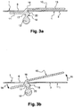
- a valve according to an exemplary implementation of the invention comprises an inner conduit and operates with a flap 10 movable in rotation, between a fully open position, for which it allows the passage of gases in the conduit with a maximum flow rate , and a closed position for which it completely closes said conduit.
- the flap 10 is generally rectangular and comprises a first rectangular portion 11 and a second portion 13 situated on either side of an axis 12 of rotation, said portions 11 being flat, in perfect continuity with one another, and being fixed to each other rigidly. More specifically, the first portion 10 and the second portion 13 meet at an interface plane 16, said flap 10 being provided with a lever arm 17 originating at said interface plane 16 and ending with the axis of rotation 12.
- This lever arm 17 is substantially perpendicular to the plane of the flap 10 constituted by the first 10 and the second 13 parts. It should be noted that the seal presented to the figure 2 is deliberately transparent, even if it has no physical reality since it is generally but not necessarily made of stainless steel, so as to show its position relative to the flap 10.
- the shutter 10 described is rotatably mounted in the valve, so that, in the closed position, the first portion 11 of the shutter 10 closes the opening 6 by coming into contact with a face of said seal 1, and so that the second portion 13 of the flap 10 is flush with the opposite face of said seal 1 at the solid portion 3.
- the axis of rotation 12 of the flap 10 is placed at the right of the opening 6 of the seal 1, at the level of the solid portion 3. of the zone of said opening 6 closest to the solid zone 3 of the joint 1.
- the two parts 11, 13 simultaneously pivot in the direction indicated by the two arrows 14, 15 to move away from the face of the gasket 1 against which they were resting or outcrop.
- the first portion 11 of the flap 10 releases the opening 6 of the seal 10, to ensure the passage of gases in the conduit. It should be noted that the rotation of the flap 10 is controlled, and that it can be fixed in a multiplicity of intermediate positions located between the closed position and the fully open position.
- the seal 1 of a valve is made in one piece, and is extended so as to cover the four peripheral edges of the flap 10.
- this seal 1 n ' is not maintained he has a structurally weak central zone, which is liable to deform under the combined effect of the high pressure and temperature of the gases.
- the seal 1 since the seal 1 is fixed at its periphery 2, only its central portion, which is not clamped in motion, will suffer the effects of thermal expansion. This deformation may cause the seal 1 to buckle, creating hollows 4 at the solid portion 3 bordering the opening 6.
- a deformed seal 1 having depressions 4 may come to impede the rotation mechanism of the flap 10 in the valve, bearing against said flap 10 and blocking its rotation.
- the flap 10 of the valve avoids deformation of the seal 1, being provided with an elongated bulge 18, implanted on the lever arm 17 of the flap 10, so that its longitudinal axis extends parallel to the axis of rotation 12 of the flap 10.
- This bulge 18 is positioned between the second portion 13 of the flap 10 and the axis of rotation 12, and protrudes from the lever arm 17 towards the second Part 13 of the flap 10.
- This bulge 18 includes the second portion 13 of the flap 10 a free space to be occupied by the solid portion 3 of the seal 1.
- the cross section of the bulge 18 has a rectilinear segment 19 and a curved segment 20, whose two ends join the two ends of said rectilinear segment 19.
- the rectilinear segment 19 corresponds to the base of the bulge 18 by which said bulge 18 is implanted on the lever arm 17, and the rounded segment 20 corresponds to the surface. This outer portion of the rounded portion of the bulge 18, which protrudes from said lever arm 17 parallel to the second portion 13 of the flap.
- the bulge 18 is placed on the lever arm 17 and is dimensioned so that it can support the zone of the solid portion 3 of the seal 1, which borders the opening 6 of said seal 1. More exactly, it is the end of the solid portion 3 of the seal 1 delimiting the opening 6, which comes into contact with the rounded outer surface 20 of the bulge 18.
- the bulge 18 also pivots, but remains in contact with the solid portion 3 of the seal 1.
- the rounded portion 20 of the bulge 18 according to the example described is designed to ensure a consistent and constant contact with the solid portion 3 of the seal 1 during the entire rotational movement of the flap 10.
- the bulge 18 shown does not approach or move away from the solid portion 3 of the seal 1 during the rotation of the flap 10.
- the bulge 18 of the flap 10 shown acts as a support stop of the portion full 3 of the seal 1 during the rotational movements of the flap 10 to move from a closed position to an open position, and vice versa.
- This bulge 18 prevents the seal 1 from being deformed by thermal expansion and contributes to preserving satisfactory operating conditions of the valve, even in the presence of hot gases under pressure.
Landscapes
- Engineering & Computer Science (AREA)
- General Engineering & Computer Science (AREA)
- Mechanical Engineering (AREA)
- Chemical & Material Sciences (AREA)
- Combustion & Propulsion (AREA)
- Lift Valve (AREA)
- Exhaust-Gas Circulating Devices (AREA)
- Gasket Seals (AREA)
Priority Applications (1)
| Application Number | Priority Date | Filing Date | Title |
|---|---|---|---|
| PL13739760T PL2870390T3 (pl) | 2012-07-04 | 2013-07-01 | Zawór sterujący silnikiem, o poprawionym działaniu |
Applications Claiming Priority (2)
| Application Number | Priority Date | Filing Date | Title |
|---|---|---|---|
| FR1256392A FR2993031B1 (fr) | 2012-07-04 | 2012-07-04 | Vanne de controle moteur a fonctionnement ameliore |
| PCT/FR2013/051537 WO2014006312A1 (fr) | 2012-07-04 | 2013-07-01 | Vanne de controle moteur a fonctionnement ameliore |
Publications (2)
| Publication Number | Publication Date |
|---|---|
| EP2870390A1 EP2870390A1 (fr) | 2015-05-13 |
| EP2870390B1 true EP2870390B1 (fr) | 2016-08-17 |
Family
ID=46826786
Family Applications (1)
| Application Number | Title | Priority Date | Filing Date |
|---|---|---|---|
| EP13739760.0A Not-in-force EP2870390B1 (fr) | 2012-07-04 | 2013-07-01 | Vanne de controle moteur a fonctionnement ameliore |
Country Status (7)
| Country | Link |
|---|---|
| US (1) | US20150136061A1 (ja) |
| EP (1) | EP2870390B1 (ja) |
| JP (1) | JP6133418B2 (ja) |
| KR (1) | KR20150027294A (ja) |
| FR (1) | FR2993031B1 (ja) |
| PL (1) | PL2870390T3 (ja) |
| WO (1) | WO2014006312A1 (ja) |
Families Citing this family (2)
| Publication number | Priority date | Publication date | Assignee | Title |
|---|---|---|---|---|
| FR2993032B1 (fr) * | 2012-07-04 | 2014-07-11 | Valeo Sys Controle Moteur Sas | Vanne de controle moteur a etancheite amelioree |
| FR3046435B1 (fr) * | 2016-01-06 | 2019-05-10 | Valeo Systemes De Controle Moteur | Vanne de regulation de gaz d'echappement |
Family Cites Families (14)
| Publication number | Priority date | Publication date | Assignee | Title |
|---|---|---|---|---|
| US3753549A (en) * | 1972-12-11 | 1973-08-21 | Arco Ind Corp | Flow control device and method and apparatus for making same |
| US4225114A (en) * | 1978-10-19 | 1980-09-30 | General Signal Corporation | Butterfly valve with improved shaft connection |
| US4289297A (en) * | 1979-04-20 | 1981-09-15 | Tomoe Technical Research Company | Butterfly valve |
| DE19718862B4 (de) * | 1996-05-08 | 2008-03-06 | Vetec Ventiltechnik Gmbh | Drehkegelventil |
| JP2002089297A (ja) * | 2000-09-08 | 2002-03-27 | Taiho Kogyo Co Ltd | 可変吸気装置 |
| FR2894315B1 (fr) * | 2005-12-02 | 2008-02-15 | Valeo Sys Controle Moteur Sas | Vanne comportant des moyens d'actionnement entre deux conduits de sortie. |
| CN101512137B (zh) * | 2006-09-14 | 2012-01-18 | 胡斯华纳有限公司 | 燃料供应组件 |
| FR2933469B1 (fr) * | 2008-07-01 | 2013-01-11 | Valeo Sys Controle Moteur Sas | Ensemble d'un corps de vanne et d'un joint d'etancheite, ensemble d'un corps de vanne,d'un joint d'etancheite et d'une canalisation,joint pour l'ensemble |
| CH700100B1 (de) * | 2008-12-12 | 2013-02-28 | Inficon Gmbh | Ventil. |
| JP5359324B2 (ja) * | 2009-01-30 | 2013-12-04 | 大豊工業株式会社 | 内燃機関の排気絞り弁 |
| JP2011074841A (ja) * | 2009-09-30 | 2011-04-14 | Denso Corp | Egr装置 |
| FR2962184B1 (fr) * | 2010-06-30 | 2013-12-27 | Valeo Systemes De Controle Moteur | Vanne de circulation de fluide |
| FR2962183B1 (fr) * | 2010-06-30 | 2013-06-28 | Valeo Sys Controle Moteur Sas | Vanne de circulation de fluide |
| FR2962182B1 (fr) * | 2010-06-30 | 2012-07-27 | Valeo Sys Controle Moteur Sas | Vanne de circulation de fluide |
-
2012
- 2012-07-04 FR FR1256392A patent/FR2993031B1/fr not_active Expired - Fee Related
-
2013
- 2013-07-01 PL PL13739760T patent/PL2870390T3/pl unknown
- 2013-07-01 JP JP2015519303A patent/JP6133418B2/ja not_active Expired - Fee Related
- 2013-07-01 EP EP13739760.0A patent/EP2870390B1/fr not_active Not-in-force
- 2013-07-01 WO PCT/FR2013/051537 patent/WO2014006312A1/fr active Application Filing
- 2013-07-01 US US14/411,924 patent/US20150136061A1/en not_active Abandoned
- 2013-07-01 KR KR1020157002731A patent/KR20150027294A/ko not_active Application Discontinuation
Also Published As
| Publication number | Publication date |
|---|---|
| US20150136061A1 (en) | 2015-05-21 |
| FR2993031A1 (fr) | 2014-01-10 |
| JP2015524527A (ja) | 2015-08-24 |
| PL2870390T3 (pl) | 2017-07-31 |
| CN104487746A (zh) | 2015-04-01 |
| JP6133418B2 (ja) | 2017-05-24 |
| FR2993031B1 (fr) | 2015-05-01 |
| KR20150027294A (ko) | 2015-03-11 |
| EP2870390A1 (fr) | 2015-05-13 |
| WO2014006312A1 (fr) | 2014-01-09 |
Similar Documents
| Publication | Publication Date | Title |
|---|---|---|
| EP1507080B1 (fr) | Tuyère convergente divergente de turboréacteur | |
| FR2712632A1 (fr) | Aubage de guidage pour moteur à turbine à gas. Invention George PASK. | |
| FR2854200A1 (fr) | Echappement pour moteur a combustion interne | |
| EP2872801B1 (fr) | Vanne de controle moteur a etancheite amelioree | |
| EP2870390B1 (fr) | Vanne de controle moteur a fonctionnement ameliore | |
| WO2011000787A1 (fr) | Vanne à boisseau, boisseau pour une telle vanne et circuit d'admission de gaz dans un moteur thermique de véhicule automobile avec une telle vanne | |
| EP1517032B1 (fr) | Volet chaud commandé de tuyère axisymétrique de turboréacteur | |
| EP2877762B1 (fr) | Vanne de controle moteur a fonctionnement ameliore | |
| EP2901049B1 (fr) | Vanne de contrôle moteur à étanchéité améliorée | |
| EP3194816B1 (fr) | Vanne de controle moteur dans un vehicule automobile | |
| EP3194817A1 (fr) | Vanne de contrôle moteur dans un véhicule automobile | |
| FR3009055A1 (fr) | Vanne, notamment pour moteur thermique | |
| EP2825801B1 (fr) | Vanne de circulation d'un fluide | |
| WO2014006311A1 (fr) | Vanne de contrôle moteur à étanchéité améliorée | |
| FR3068433A1 (fr) | Ensemble comportant un receptacle et une vanne de regulation de debit d'un gaz destines a etre assembles | |
| EP2917617B1 (fr) | Vanne, notamment pour circuit d'air de moteur thermique | |
| FR3103020A1 (fr) | Vanne à clapet coulissant et véhicule automobile le comportant | |
| WO2019002731A1 (fr) | Vanne de régulation de débit d'un gaz destinée a être assemblée a un réceptacle et ensemble comprenant une telle vanne | |
| FR3068432A1 (fr) | Ensemble comportant un receptacle et une vanne de regulation de debit d'un gaz destines a etre assembles | |
| FR3068431A1 (fr) | Vanne de regulation de debit d'un gaz |
Legal Events
| Date | Code | Title | Description |
|---|---|---|---|
| PUAI | Public reference made under article 153(3) epc to a published international application that has entered the european phase |
Free format text: ORIGINAL CODE: 0009012 |
|
| 17P | Request for examination filed |
Effective date: 20141223 |
|
| AK | Designated contracting states |
Kind code of ref document: A1 Designated state(s): AL AT BE BG CH CY CZ DE DK EE ES FI FR GB GR HR HU IE IS IT LI LT LU LV MC MK MT NL NO PL PT RO RS SE SI SK SM TR |
|
| AX | Request for extension of the european patent |
Extension state: BA ME |
|
| DAX | Request for extension of the european patent (deleted) | ||
| GRAP | Despatch of communication of intention to grant a patent |
Free format text: ORIGINAL CODE: EPIDOSNIGR1 |
|
| INTG | Intention to grant announced |
Effective date: 20160218 |
|
| RIC1 | Information provided on ipc code assigned before grant |
Ipc: F02M 26/00 20160101ALI20160224BHEP Ipc: F16K 11/052 20060101ALI20160224BHEP Ipc: F16K 1/20 20060101ALI20160224BHEP Ipc: F16K 1/226 20060101AFI20160224BHEP |
|
| GRAS | Grant fee paid |
Free format text: ORIGINAL CODE: EPIDOSNIGR3 |
|
| GRAA | (expected) grant |
Free format text: ORIGINAL CODE: 0009210 |
|
| AK | Designated contracting states |
Kind code of ref document: B1 Designated state(s): AL AT BE BG CH CY CZ DE DK EE ES FI FR GB GR HR HU IE IS IT LI LT LU LV MC MK MT NL NO PL PT RO RS SE SI SK SM TR |
|
| REG | Reference to a national code |
Ref country code: GB Ref legal event code: FG4D Free format text: NOT ENGLISH |
|
| REG | Reference to a national code |
Ref country code: CH Ref legal event code: EP |
|
| REG | Reference to a national code |
Ref country code: IE Ref legal event code: FG4D Free format text: LANGUAGE OF EP DOCUMENT: FRENCH |
|
| REG | Reference to a national code |
Ref country code: AT Ref legal event code: REF Ref document number: 821435 Country of ref document: AT Kind code of ref document: T Effective date: 20160915 |
|
| REG | Reference to a national code |
Ref country code: DE Ref legal event code: R096 Ref document number: 602013010405 Country of ref document: DE |
|
| REG | Reference to a national code |
Ref country code: NL Ref legal event code: MP Effective date: 20160817 |
|
| REG | Reference to a national code |
Ref country code: LT Ref legal event code: MG4D |
|
| REG | Reference to a national code |
Ref country code: AT Ref legal event code: MK05 Ref document number: 821435 Country of ref document: AT Kind code of ref document: T Effective date: 20160817 |
|
| PG25 | Lapsed in a contracting state [announced via postgrant information from national office to epo] |
Ref country code: NL Free format text: LAPSE BECAUSE OF FAILURE TO SUBMIT A TRANSLATION OF THE DESCRIPTION OR TO PAY THE FEE WITHIN THE PRESCRIBED TIME-LIMIT Effective date: 20160817 Ref country code: LT Free format text: LAPSE BECAUSE OF FAILURE TO SUBMIT A TRANSLATION OF THE DESCRIPTION OR TO PAY THE FEE WITHIN THE PRESCRIBED TIME-LIMIT Effective date: 20160817 Ref country code: HR Free format text: LAPSE BECAUSE OF FAILURE TO SUBMIT A TRANSLATION OF THE DESCRIPTION OR TO PAY THE FEE WITHIN THE PRESCRIBED TIME-LIMIT Effective date: 20160817 Ref country code: RS Free format text: LAPSE BECAUSE OF FAILURE TO SUBMIT A TRANSLATION OF THE DESCRIPTION OR TO PAY THE FEE WITHIN THE PRESCRIBED TIME-LIMIT Effective date: 20160817 Ref country code: FI Free format text: LAPSE BECAUSE OF FAILURE TO SUBMIT A TRANSLATION OF THE DESCRIPTION OR TO PAY THE FEE WITHIN THE PRESCRIBED TIME-LIMIT Effective date: 20160817 Ref country code: NO Free format text: LAPSE BECAUSE OF FAILURE TO SUBMIT A TRANSLATION OF THE DESCRIPTION OR TO PAY THE FEE WITHIN THE PRESCRIBED TIME-LIMIT Effective date: 20161117 |
|
| PG25 | Lapsed in a contracting state [announced via postgrant information from national office to epo] |
Ref country code: GR Free format text: LAPSE BECAUSE OF FAILURE TO SUBMIT A TRANSLATION OF THE DESCRIPTION OR TO PAY THE FEE WITHIN THE PRESCRIBED TIME-LIMIT Effective date: 20161118 Ref country code: ES Free format text: LAPSE BECAUSE OF FAILURE TO SUBMIT A TRANSLATION OF THE DESCRIPTION OR TO PAY THE FEE WITHIN THE PRESCRIBED TIME-LIMIT Effective date: 20160817 Ref country code: PT Free format text: LAPSE BECAUSE OF FAILURE TO SUBMIT A TRANSLATION OF THE DESCRIPTION OR TO PAY THE FEE WITHIN THE PRESCRIBED TIME-LIMIT Effective date: 20161219 Ref country code: LV Free format text: LAPSE BECAUSE OF FAILURE TO SUBMIT A TRANSLATION OF THE DESCRIPTION OR TO PAY THE FEE WITHIN THE PRESCRIBED TIME-LIMIT Effective date: 20160817 Ref country code: SE Free format text: LAPSE BECAUSE OF FAILURE TO SUBMIT A TRANSLATION OF THE DESCRIPTION OR TO PAY THE FEE WITHIN THE PRESCRIBED TIME-LIMIT Effective date: 20160817 Ref country code: AT Free format text: LAPSE BECAUSE OF FAILURE TO SUBMIT A TRANSLATION OF THE DESCRIPTION OR TO PAY THE FEE WITHIN THE PRESCRIBED TIME-LIMIT Effective date: 20160817 |
|
| PG25 | Lapsed in a contracting state [announced via postgrant information from national office to epo] |
Ref country code: EE Free format text: LAPSE BECAUSE OF FAILURE TO SUBMIT A TRANSLATION OF THE DESCRIPTION OR TO PAY THE FEE WITHIN THE PRESCRIBED TIME-LIMIT Effective date: 20160817 Ref country code: RO Free format text: LAPSE BECAUSE OF FAILURE TO SUBMIT A TRANSLATION OF THE DESCRIPTION OR TO PAY THE FEE WITHIN THE PRESCRIBED TIME-LIMIT Effective date: 20160817 |
|
| REG | Reference to a national code |
Ref country code: DE Ref legal event code: R097 Ref document number: 602013010405 Country of ref document: DE |
|
| PG25 | Lapsed in a contracting state [announced via postgrant information from national office to epo] |
Ref country code: DK Free format text: LAPSE BECAUSE OF FAILURE TO SUBMIT A TRANSLATION OF THE DESCRIPTION OR TO PAY THE FEE WITHIN THE PRESCRIBED TIME-LIMIT Effective date: 20160817 Ref country code: BG Free format text: LAPSE BECAUSE OF FAILURE TO SUBMIT A TRANSLATION OF THE DESCRIPTION OR TO PAY THE FEE WITHIN THE PRESCRIBED TIME-LIMIT Effective date: 20161117 Ref country code: SM Free format text: LAPSE BECAUSE OF FAILURE TO SUBMIT A TRANSLATION OF THE DESCRIPTION OR TO PAY THE FEE WITHIN THE PRESCRIBED TIME-LIMIT Effective date: 20160817 Ref country code: CZ Free format text: LAPSE BECAUSE OF FAILURE TO SUBMIT A TRANSLATION OF THE DESCRIPTION OR TO PAY THE FEE WITHIN THE PRESCRIBED TIME-LIMIT Effective date: 20160817 Ref country code: SK Free format text: LAPSE BECAUSE OF FAILURE TO SUBMIT A TRANSLATION OF THE DESCRIPTION OR TO PAY THE FEE WITHIN THE PRESCRIBED TIME-LIMIT Effective date: 20160817 |
|
| PLBE | No opposition filed within time limit |
Free format text: ORIGINAL CODE: 0009261 |
|
| STAA | Information on the status of an ep patent application or granted ep patent |
Free format text: STATUS: NO OPPOSITION FILED WITHIN TIME LIMIT |
|
| 26N | No opposition filed |
Effective date: 20170518 |
|
| REG | Reference to a national code |
Ref country code: FR Ref legal event code: PLFP Year of fee payment: 5 |
|
| PG25 | Lapsed in a contracting state [announced via postgrant information from national office to epo] |
Ref country code: SI Free format text: LAPSE BECAUSE OF FAILURE TO SUBMIT A TRANSLATION OF THE DESCRIPTION OR TO PAY THE FEE WITHIN THE PRESCRIBED TIME-LIMIT Effective date: 20160817 |
|
| REG | Reference to a national code |
Ref country code: CH Ref legal event code: PL |
|
| REG | Reference to a national code |
Ref country code: IE Ref legal event code: MM4A |
|
| PG25 | Lapsed in a contracting state [announced via postgrant information from national office to epo] |
Ref country code: LI Free format text: LAPSE BECAUSE OF NON-PAYMENT OF DUE FEES Effective date: 20170731 Ref country code: IE Free format text: LAPSE BECAUSE OF NON-PAYMENT OF DUE FEES Effective date: 20170701 Ref country code: CH Free format text: LAPSE BECAUSE OF NON-PAYMENT OF DUE FEES Effective date: 20170731 |
|
| REG | Reference to a national code |
Ref country code: BE Ref legal event code: MM Effective date: 20170731 |
|
| PG25 | Lapsed in a contracting state [announced via postgrant information from national office to epo] |
Ref country code: LU Free format text: LAPSE BECAUSE OF NON-PAYMENT OF DUE FEES Effective date: 20170701 |
|
| REG | Reference to a national code |
Ref country code: FR Ref legal event code: PLFP Year of fee payment: 6 |
|
| PG25 | Lapsed in a contracting state [announced via postgrant information from national office to epo] |
Ref country code: BE Free format text: LAPSE BECAUSE OF NON-PAYMENT OF DUE FEES Effective date: 20170731 |
|
| PG25 | Lapsed in a contracting state [announced via postgrant information from national office to epo] |
Ref country code: MT Free format text: LAPSE BECAUSE OF FAILURE TO SUBMIT A TRANSLATION OF THE DESCRIPTION OR TO PAY THE FEE WITHIN THE PRESCRIBED TIME-LIMIT Effective date: 20160817 |
|
| PG25 | Lapsed in a contracting state [announced via postgrant information from national office to epo] |
Ref country code: AL Free format text: LAPSE BECAUSE OF FAILURE TO SUBMIT A TRANSLATION OF THE DESCRIPTION OR TO PAY THE FEE WITHIN THE PRESCRIBED TIME-LIMIT Effective date: 20160817 |
|
| PG25 | Lapsed in a contracting state [announced via postgrant information from national office to epo] |
Ref country code: MC Free format text: LAPSE BECAUSE OF FAILURE TO SUBMIT A TRANSLATION OF THE DESCRIPTION OR TO PAY THE FEE WITHIN THE PRESCRIBED TIME-LIMIT Effective date: 20160817 Ref country code: HU Free format text: LAPSE BECAUSE OF FAILURE TO SUBMIT A TRANSLATION OF THE DESCRIPTION OR TO PAY THE FEE WITHIN THE PRESCRIBED TIME-LIMIT; INVALID AB INITIO Effective date: 20130701 |
|
| PGFP | Annual fee paid to national office [announced via postgrant information from national office to epo] |
Ref country code: PL Payment date: 20190626 Year of fee payment: 7 |
|
| PG25 | Lapsed in a contracting state [announced via postgrant information from national office to epo] |
Ref country code: CY Free format text: LAPSE BECAUSE OF FAILURE TO SUBMIT A TRANSLATION OF THE DESCRIPTION OR TO PAY THE FEE WITHIN THE PRESCRIBED TIME-LIMIT Effective date: 20160817 |
|
| PGFP | Annual fee paid to national office [announced via postgrant information from national office to epo] |
Ref country code: FR Payment date: 20190731 Year of fee payment: 7 Ref country code: DE Payment date: 20190711 Year of fee payment: 7 Ref country code: IT Payment date: 20190724 Year of fee payment: 7 |
|
| PG25 | Lapsed in a contracting state [announced via postgrant information from national office to epo] |
Ref country code: MK Free format text: LAPSE BECAUSE OF FAILURE TO SUBMIT A TRANSLATION OF THE DESCRIPTION OR TO PAY THE FEE WITHIN THE PRESCRIBED TIME-LIMIT Effective date: 20160817 |
|
| PGFP | Annual fee paid to national office [announced via postgrant information from national office to epo] |
Ref country code: GB Payment date: 20190719 Year of fee payment: 7 |
|
| PG25 | Lapsed in a contracting state [announced via postgrant information from national office to epo] |
Ref country code: TR Free format text: LAPSE BECAUSE OF FAILURE TO SUBMIT A TRANSLATION OF THE DESCRIPTION OR TO PAY THE FEE WITHIN THE PRESCRIBED TIME-LIMIT Effective date: 20160817 |
|
| PG25 | Lapsed in a contracting state [announced via postgrant information from national office to epo] |
Ref country code: IS Free format text: LAPSE BECAUSE OF FAILURE TO SUBMIT A TRANSLATION OF THE DESCRIPTION OR TO PAY THE FEE WITHIN THE PRESCRIBED TIME-LIMIT Effective date: 20161217 |
|
| REG | Reference to a national code |
Ref country code: DE Ref legal event code: R119 Ref document number: 602013010405 Country of ref document: DE |
|
| GBPC | Gb: european patent ceased through non-payment of renewal fee |
Effective date: 20200701 |
|
| PG25 | Lapsed in a contracting state [announced via postgrant information from national office to epo] |
Ref country code: GB Free format text: LAPSE BECAUSE OF NON-PAYMENT OF DUE FEES Effective date: 20200701 Ref country code: FR Free format text: LAPSE BECAUSE OF NON-PAYMENT OF DUE FEES Effective date: 20200731 |
|
| PG25 | Lapsed in a contracting state [announced via postgrant information from national office to epo] |
Ref country code: DE Free format text: LAPSE BECAUSE OF NON-PAYMENT OF DUE FEES Effective date: 20210202 |
|
| PG25 | Lapsed in a contracting state [announced via postgrant information from national office to epo] |
Ref country code: IT Free format text: LAPSE BECAUSE OF NON-PAYMENT OF DUE FEES Effective date: 20200701 |
|
| PG25 | Lapsed in a contracting state [announced via postgrant information from national office to epo] |
Ref country code: PL Free format text: LAPSE BECAUSE OF NON-PAYMENT OF DUE FEES Effective date: 20200701 |