EP2868445A1 - Procédé de programmation de déroulements de mouvement d'un robot industriel redondant et robot industriel associé - Google Patents
Procédé de programmation de déroulements de mouvement d'un robot industriel redondant et robot industriel associé Download PDFInfo
- Publication number
- EP2868445A1 EP2868445A1 EP20140191772 EP14191772A EP2868445A1 EP 2868445 A1 EP2868445 A1 EP 2868445A1 EP 20140191772 EP20140191772 EP 20140191772 EP 14191772 A EP14191772 A EP 14191772A EP 2868445 A1 EP2868445 A1 EP 2868445A1
- Authority
- EP
- European Patent Office
- Prior art keywords
- manipulator arm
- robot
- joint
- redundant
- joints
- Prior art date
- Legal status (The legal status is an assumption and is not a legal conclusion. Google has not performed a legal analysis and makes no representation as to the accuracy of the status listed.)
- Granted
Links
- 238000000034 method Methods 0.000 title claims abstract description 49
- 238000005457 optimization Methods 0.000 claims description 13
- 230000035945 sensitivity Effects 0.000 claims description 7
- 230000003068 static effect Effects 0.000 claims description 6
- 230000001133 acceleration Effects 0.000 claims description 5
- 210000001503 joint Anatomy 0.000 description 46
- 238000003754 machining Methods 0.000 description 10
- 210000002310 elbow joint Anatomy 0.000 description 6
- 238000000227 grinding Methods 0.000 description 4
- 101100129500 Caenorhabditis elegans max-2 gene Proteins 0.000 description 3
- 238000013459 approach Methods 0.000 description 3
- 238000005553 drilling Methods 0.000 description 3
- 238000003801 milling Methods 0.000 description 3
- 239000012636 effector Substances 0.000 description 2
- 230000005484 gravity Effects 0.000 description 2
- 238000005498 polishing Methods 0.000 description 2
- 238000012545 processing Methods 0.000 description 2
- 238000007630 basic procedure Methods 0.000 description 1
- 238000004364 calculation method Methods 0.000 description 1
- 239000012141 concentrate Substances 0.000 description 1
- 238000012937 correction Methods 0.000 description 1
- 238000013461 design Methods 0.000 description 1
- 238000010586 diagram Methods 0.000 description 1
- 238000006073 displacement reaction Methods 0.000 description 1
- 230000002349 favourable effect Effects 0.000 description 1
- 238000005304 joining Methods 0.000 description 1
- 238000005259 measurement Methods 0.000 description 1
- 230000001404 mediated effect Effects 0.000 description 1
- 238000003825 pressing Methods 0.000 description 1
- 238000012546 transfer Methods 0.000 description 1
Images


Classifications
-
- B—PERFORMING OPERATIONS; TRANSPORTING
- B25—HAND TOOLS; PORTABLE POWER-DRIVEN TOOLS; MANIPULATORS
- B25J—MANIPULATORS; CHAMBERS PROVIDED WITH MANIPULATION DEVICES
- B25J9/00—Programme-controlled manipulators
- B25J9/0081—Programme-controlled manipulators with master teach-in means
-
- B—PERFORMING OPERATIONS; TRANSPORTING
- B25—HAND TOOLS; PORTABLE POWER-DRIVEN TOOLS; MANIPULATORS
- B25J—MANIPULATORS; CHAMBERS PROVIDED WITH MANIPULATION DEVICES
- B25J9/00—Programme-controlled manipulators
- B25J9/02—Programme-controlled manipulators characterised by movement of the arms, e.g. cartesian coordinate type
-
- B—PERFORMING OPERATIONS; TRANSPORTING
- B25—HAND TOOLS; PORTABLE POWER-DRIVEN TOOLS; MANIPULATORS
- B25J—MANIPULATORS; CHAMBERS PROVIDED WITH MANIPULATION DEVICES
- B25J9/00—Programme-controlled manipulators
- B25J9/06—Programme-controlled manipulators characterised by multi-articulated arms
-
- B—PERFORMING OPERATIONS; TRANSPORTING
- B25—HAND TOOLS; PORTABLE POWER-DRIVEN TOOLS; MANIPULATORS
- B25J—MANIPULATORS; CHAMBERS PROVIDED WITH MANIPULATION DEVICES
- B25J9/00—Programme-controlled manipulators
- B25J9/16—Programme controls
- B25J9/1628—Programme controls characterised by the control loop
- B25J9/1643—Programme controls characterised by the control loop redundant control
-
- B—PERFORMING OPERATIONS; TRANSPORTING
- B25—HAND TOOLS; PORTABLE POWER-DRIVEN TOOLS; MANIPULATORS
- B25J—MANIPULATORS; CHAMBERS PROVIDED WITH MANIPULATION DEVICES
- B25J9/00—Programme-controlled manipulators
- B25J9/16—Programme controls
- B25J9/1656—Programme controls characterised by programming, planning systems for manipulators
-
- G—PHYSICS
- G05—CONTROLLING; REGULATING
- G05B—CONTROL OR REGULATING SYSTEMS IN GENERAL; FUNCTIONAL ELEMENTS OF SUCH SYSTEMS; MONITORING OR TESTING ARRANGEMENTS FOR SUCH SYSTEMS OR ELEMENTS
- G05B19/00—Programme-control systems
- G05B19/02—Programme-control systems electric
- G05B19/42—Recording and playback systems, i.e. in which the programme is recorded from a cycle of operations, e.g. the cycle of operations being manually controlled, after which this record is played back on the same machine
- G05B19/423—Teaching successive positions by walk-through, i.e. the tool head or end effector being grasped and guided directly, with or without servo-assistance, to follow a path
-
- G—PHYSICS
- G05—CONTROLLING; REGULATING
- G05B—CONTROL OR REGULATING SYSTEMS IN GENERAL; FUNCTIONAL ELEMENTS OF SUCH SYSTEMS; MONITORING OR TESTING ARRANGEMENTS FOR SUCH SYSTEMS OR ELEMENTS
- G05B2219/00—Program-control systems
- G05B2219/30—Nc systems
- G05B2219/36—Nc in input of data, input key till input tape
- G05B2219/36432—By putting some constraints on some DOF, move within limited volumes, areas, planes, limits motion in x, y or z planes, virtual reality constraints
-
- G—PHYSICS
- G05—CONTROLLING; REGULATING
- G05B—CONTROL OR REGULATING SYSTEMS IN GENERAL; FUNCTIONAL ELEMENTS OF SUCH SYSTEMS; MONITORING OR TESTING ARRANGEMENTS FOR SUCH SYSTEMS OR ELEMENTS
- G05B2219/00—Program-control systems
- G05B2219/30—Nc systems
- G05B2219/40—Robotics, robotics mapping to robotics vision
- G05B2219/40365—Configuration control, select other tasks by configuration of link positions
-
- Y—GENERAL TAGGING OF NEW TECHNOLOGICAL DEVELOPMENTS; GENERAL TAGGING OF CROSS-SECTIONAL TECHNOLOGIES SPANNING OVER SEVERAL SECTIONS OF THE IPC; TECHNICAL SUBJECTS COVERED BY FORMER USPC CROSS-REFERENCE ART COLLECTIONS [XRACs] AND DIGESTS
- Y10—TECHNICAL SUBJECTS COVERED BY FORMER USPC
- Y10S—TECHNICAL SUBJECTS COVERED BY FORMER USPC CROSS-REFERENCE ART COLLECTIONS [XRACs] AND DIGESTS
- Y10S901/00—Robots
- Y10S901/02—Arm motion controller
- Y10S901/03—Teaching system
- Y10S901/04—Manual lead through
Definitions
- the invention relates to a method for programming movements of a redundant industrial robot by manually adjusting the pose of a manipulator arm of the industrial robot having a plurality of consecutive members which are connected by adjustable, at least one redundant joint joints comprising at least one robot controller of the industrial robot are controlled adjustable.
- the invention also relates to an associated industrial robot.
- a method for controlling a robot in particular a human collaborating robot, in which a robotic or task-specific redundancy of the robot is resolved.
- a human-collaborating robot is in particular referred to as a robot that interacts physically with a human being, for example, by providing a human residence in a working space of the robot.
- limit values have been specified for this purpose, for example according to ISO-10218, for example a maximum speed of a tool reference point, the so-called Tool Center Point (TCP) of 0.2 to 0.25 m / s.
- TCP Tool Center Point
- Such human-collaborating robots are available on the market and are called, among other things, as lightweight robots.
- the object of the invention is to program the movement sequences of a redundant industrial robot by manually adjusting the pose of a manipulator arm of the industrial robot, in particular to simplify it.
- a redundant industrial robot is understood to mean a manipulator arm that can be moved by means of a robot controller, which has more manipulative degrees of freedom than are necessary to perform a task.
- the degree of redundancy results from the difference in the number of degrees of freedom of the manipulator arm and the dimension of the event space in which the task is to be solved. It may be a kinematic redundancy or a task-specific redundancy.
- the number of kinematic degrees of freedom generally the number of joints of the manipulator arm, is greater than the event space which, in a real environment when moving in space, is formed by the three translational and three rotational degrees of freedom, ie by six degrees of freedom becomes.
- a redundant industrial robot may therefore be, for example, a lightweight robot with seven joints, in particular seven hinges.
- the dimension of the task is smaller than the number of kinematic degrees of freedom of the manipulator.
- Manipulator arms with associated robot controls are working machines that can be equipped for the automatic handling and / or machining of objects with tools and in several axes of motion, for example, in terms of orientation, position and workflow are programmable.
- Industrial robots typically include a manipulator arm having a plurality of links connected by joints and programmable robotic controls (control devices) that automatically control or regulate the movements of the manipulator arm during operation.
- the links are moved via drives, in particular electric drives, which are controlled by the robot control, in particular with respect to the axes of movement of the industrial robot, which represent the degrees of freedom of movement of the joints.
- a multiple articulated manipulator arm may be configured as an articulated robot having a plurality of links and joints serially arranged, in particular, the redundant industrial robot may include a manipulator arm having seven or more joints.
- manipulator arms with associated robot controls such as industrial robots
- manipulator arms with associated robot controls may in particular be so-called lightweight robots, which initially differ from conventional industrial robots in that they have a favorable size for man-machine cooperation and thereby have a relatively high load capacity relative to their own weight.
- lightweight robots can be operated in particular force-controlled instead of position-controlled, which simplifies, for example, a manual adjustment of the pose of the manipulator.
- a safe human-machine cooperation can be achieved because, for example, unintentional collisions of the manipulator arm with persons can either be prevented or at least mitigated so that the persons are not harmed.
- Such a manipulator arm or such a lightweight robot usually has more than six degrees of freedom, so that in this respect an over-determined system is created, whereby the same point in space in the same orientation in several, especially even infinitely many different poses of the manipulator arm can be achieved.
- the lightweight robot can respond to external forces in appropriate ways.
- force sensors can be used which can measure forces and torques in all three spatial directions.
- the external forces can also be estimated without sensors, for example based on the measured motor currents of the drives at the joints of the lightweight robot.
- control concepts for example, an indirect Force control by modeling the lightweight robot as a mechanical resistance (impedance) or a direct force control can be used.
- the pose of the manipulator arm is quite generally understood the sum of all joint positions of joints of the manipulator arm, which adjustably connect the individual members of the manipulator arm.
- a reference point such as a tool reference point (Tool Center Points / TCP) of the manipulator arm
- the tool reference point can be formed, for example, by a suitable point on a hand flange of the manipulator arm, to which a gripper, a tool or other device is attached in order to move it by adjusting the pose of the manipulator arm in space.
- the tool reference point can be a virtual space point also outside the manipulator arm, but which is geometrically rigidly connected to one of the links of the manipulator arm, in particular the hand flange of the manipulator arm.
- Manual manipulation of the pose of the manipulator arm is generally understood to alter the instantaneous articulations of the manipulator arm by having an operator of the robotic manipulator grasp the manipulator arm at one or more of its joints and, for example, depress, pull and / or rotate the gripped handle Limb or the gripped limbs changed the pose of the manipulator arm, ie adjusted.
- an executive can also be initiated by direct gripping, in particular embracing the last member of the manipulator arm in the kinematic chain into the mechanical structure of the manipulator arm.
- Such an executive force applied by the operator of the industrial robot to the manipulator arm can for example be measured directly by specially trained and equipped sensors, in particular force sensors, or indirectly calculated from measured values on already existing joint sensors, in particular force / moment sensors of the manipulator arm or indirectly from motor currents of the drives of the joints of the industrial robot.
- a manual adjustment of the manipulator instead of by guiding by hand, possibly also by methods via an operating device, in particular by pressing, or a joystick done.
- a seven-axis lightweight robot has a kinematic redundant structure that covers the six possible directions of movement in space by seven degrees of freedom of the robot.
- a tool reference point for example a TCP of an end effector
- a widely used method for resolving this redundancy is the definition of a redundancy circle, which is described by different positions, for example, of the elbow.
- An ideal position of the elbow joint during movement is not known, since this is to be chosen differently from application to application.
- there are different approaches for example, a good controllability, a large range of motion in terms of singularities and Prioritize joint angle restrictions or a low load on the drives.
- a main advantage of a lightweight robot is its integrated force sensor, which makes a hand-teaching of the robot - ie a guide of the robot for programming by hand - very simple. Due to the redundancy here not only the pose of the tool reference point can be hand-guided, but also the position of the elbow can be specified manually.
- the position of the elbow may, in particular, be understood as meaning a combination of joint angles, ie the pose (position and orientation) of a joint-fixed coordinate system in space or in the plane.
- This procedure is very user-friendly and generates well-predictable robot movements.
- the user defines by his concrete specification of the position not only the pose of the tool reference point, but also always the performance of the robot.
- This performance expressed in terms of the so-called kinetostatic properties, ie, for example, the force and velocity transfer from Cartesian to the Achsraum and vice versa, the accuracy and rigidity that reaches the robot in a given TCP pose is not only very inhomogeneous in the working space of the But also varies over the redundancy parameter, the exemplary elbow position.
- the characteristics of the robot in a particular pose and position are very difficult and predictable with high expertise. An inexperienced user can thus program the robot very easily, but also unconsciously and quickly give it worse qualities.
- the tool reference point may also be referred to as a tool center point (TCP) and may be, for example, an operating point of a tool attached to the last link of the manipulator arm, the hand flange.
- TCP tool center point
- the tool reference point or the tool center point (TCP) for example, be a fixed point on the hand flange of the manipulator arm.
- the coordinates of this point in space represented in space by, for example, three position values (X, Y, Z) and three orientation values (A, B, C) are determined in a robot program of the robot controller stored as position values. Movements can thus be accomplished by a sequence of multiple stored poses of the tool reference point be programmed. The stored poses of the tool reference point can then be approached successively by the robot controller, for example in a point-to-point motion mode (PTP).
- PTP point-to-point motion mode
- a movement path for the tool reference point can also be determined, ie calculated in the robot control, for example in the form of straight lines (LIN), which leads from one stored pose of the tool reference point to the next, or in the form of spline curves (SPLINE). which extend over several stored poses of the tool reference point.
- LIN straight lines
- SPLINE spline curves
- the pose of the manipulator arm that is to say the overall consideration of all joint positions
- the so-called redundancy must be resolved, which means that even those or those redundant joints are assigned a unique joint position value for which an infinite number of joint position values would be possible in a recalculation of the joint position values from the respective pose of the tool reference point. This resolution of the redundancy is done so far only at the time when the robot program is already fully generated and is executed in automatic mode.
- the joint position values of all joints of the manipulator arm are recalculated from the second position and second orientation of the tool reference point of the manipulator arm with resolution of the redundancy by determining an optimized joint position value of the at least one redundant joint, and automatically adjusting all joints of the manipulator arm actuated by the robot controller based on the recalculated, optimized joint position values during manual adjustment, the operator can concentrate on programming poses and trajectories of the tool reference point without considering the pose of the entire manipulator arm, especially yourself must adjust manually.
- Another advantage is that the operator immediately Receive feedback about the later actual pose of the entire manipulator arm during the manual guided programming via the immediate automatic background calculation and adjustment of all joints of the manipulator arm. This has the additional advantage that a programming of motion sequences in a simple and fast way is possible and a useful, in particular safely executable and predictable robot program is obtained.
- an algorithm may be selected from a plurality of predefined different algorithms for calculating back the joint position values of all joints of the manipulator arm from the second position and second orientation of the tool reference point of the manipulator arm with resolution of the redundancy by determining the optimized joint position value of the at least one redundant joint respectively.
- the selection of the algorithm by an operator of the industrial robot in particular before his manual guided adjustment of the manipulator arm done.
- the operator can specify the behavior of the redundant joints, in particular the entire pose of the manipulator arm during manual programming according to certain criteria and thus a fundamental behavior of the manipulator arm of one to be programmed Adapt processing and / or handling task. This further improves the predictability of the behavior of the manipulator arm both during and after hand-held programming.
- algorithms can be stored in the robot control, which allow an automatic optimization of the joint position values of the at least one redundant joint according to different static and / or kinetic properties of the manipulator arm.
- the operator may select a desired algorithm which is then used during manual manipulation of the manipulator arm, i. the joints and in particular the redundant joints of the manipulator arm are then automatically adjusted accordingly.
- the optimization of the joint position value of the at least one redundant joint can be carried out as a function of the requirement for the motion sequences to be programmed. This can mean that each algorithm stored in the robot control is assigned a requirement matching the optimization strategy.
- the programming of the industrial robot for an operator can be simplified because he has no special knowledge of the behavior of the has to have individual algorithms, but the operator only selects a suitable task for his task, which in turn is assigned a specific algorithm in the robot controller.
- the property to be optimized can be, for example, a process force, a rigidity of the manipulator arm, a positioning accuracy of the manipulator arm, a movement speed of the manipulator arm, an acceleration capability of the manipulator arm and / or a sensitivity in the force feedback of the manipulator arm.
- a process force for example, a rigidity of the manipulator arm, a positioning accuracy of the manipulator arm, a movement speed of the manipulator arm, an acceleration capability of the manipulator arm and / or a sensitivity in the force feedback of the manipulator arm.
- the manipulator arm In another application, such as grinding or polishing, it may be necessary for the manipulator arm to have a certain flexibility, so that the workpiece can only be acted upon with a reduced maximum force by the robot-guided tool.
- the optimization of the joint position value of the at least one redundant joint can therefore also be carried out as a function of one or more predetermined effective directions become.
- a process force direction can be impressed depending on the joint positions of the manipulator, in particular the redundant joints of the manipulator either a larger moment or a smaller moment the respective considered joint.
- the one or more effective directions to be specified can be preset manually by an operator of the industrial robot before his manually guided adjustment of the manipulator arm of the robot controller or automatically determined by the robot controller, in particular from the direction of movement predetermined by the operator by manually guiding the manipulator arm automatically by the robot controller be determined.
- the robot controller can be designed and / or set up to automatically adjust or automatically adjust all joints of the manipulator arm actuated by the robot controller on the basis of the recalculated, optimized joint position values during the manually guided adjustment, a manual adjustment allow the joints of the manipulator arm, in particular the at least one redundant joint.
- the operator sees directly and in advance, especially during hand-guided programming, the later overall pose of the manipulator arm during program execution. He can visually check this Obstpose the manipulator arm during manual programming and in the above-mentioned further refinement, in which, after an automatic setting or during an automatic setting, the operator setting up on request manual adjustment of the joints of the manipulator arm, in particular of the at least one redundant joint can still perform, for example, to correct the automatically optimized overall pose of the manipulator still targeted.
- the maximum possible performance of the robot can be ensured together with the maximum possible predictability of the movement with ease of use.
- the robot controller can be designed and / or set up to allow a manual adjustment of the joints of the manipulator arm with force feedback.
- the force feedback may increase linearly or progressively with the deviation from the optimized joint position values, in particular of the at least one redundant joint.
- the object of the invention in addition to the method according to the invention as such, is also achieved by an industrial robot having a robot controller that is designed and / or configured to execute a robot program containing programmed movements, and has a redundant manipulator arm with a plurality of successive members and joints, which according to FIG the robot program are automated and / or automatically adjustable in a manual operation, wherein the robot controller is formed and / or arranged to perform a method as described.
- the entire manipulator arm assumes an overall pose directly in the hand-guided programming of the tool reference point which the manipulator arm will have later during the automatic execution of the robot program, the overall pose of the manipulator arm kinetostatisch can be optimally selected with respect to the later task.
- the operator can position and align the end effector of the manipulator arm by intuitively guiding the hand in accordance with the processing and / or handling task to be programmed.
- the operator can also specify whether the robot should meet specific requirements in the desired poses.
- These additionally programmed, in particular kinetostatic properties of the robot are added to a pose or to a movement section in the robot controller.
- Planning algorithms can use this information to calculate the currently optimal pose of the manipulator arm.
- the optimized position is transmitted directly to the drives of the joints of the manipulator arm, so that the operator can immediately see the right poses of the manipulator arm and continue to work with me.
- Programming can take place as follows. First of all, the operator selects a tool reference point with which he would like to work, ie, he would like to move his associated member of the manipulator arm by hand. For example, in a robot gravity compensation mode, the operator can manually move the tool reference point to a desired pose. For example, the position of the elbow joint is not relevant.
- a desired property can now additionally be deposited, such as an expected direction of the maximum force or torque to be generated, an expected direction of the maximum speed to be generated, an expected direction of the maximum dynamics / acceleration to be generated, a desired direction highest accuracy, a desired direction of highest sensitivity, a best controllability and / or a desired direction of highest mechanical rigidity.
- the robot is to carry out machining operations such as drilling, grinding, milling or high-precision, sensitive joining or measuring tasks, or reaches the limits of its load or cycle time in handling tasks.
- the programming of the direction may e.g. simply via the hand guide of the tool.
- a distinctive tool direction such as the impact direction, could be used or an explicit coordinate direction selected.
- the desired kinetostatic properties to a plane, i. in the desired plane, for example, the robot should have the highest accuracy possible in this pose. This can also be defined by the orientation of the tool, which in this case defines the normal vector of the plane.
- the specification of the direction can be done independently of the actual Zielpose.
- the manipulator arm can again assume its programmed pose after the definition of the property direction and thereby automatically selects the optimal position.
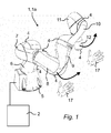
- the Fig. 1 shows an exemplary robotic workstation with a manipulator arm 1a of an industrial robot 1.
- the industrial robot 1 is executed in the exemplary embodiment as a so-called lightweight robot KUKA LBR type, the manipulator arm 1a and an associated robot controller 2 has.
- the redundant manipulator arm 1a comprises eight links 5 to 12 arranged one after the other and connected in a pivotable manner by means of seven joints 4.
- the robot controller 2 of the industrial robot 1 is configured or configured to execute a robot program, by means of which the joints 4 of the manipulator arm 1 a can be automatically automated or rotated in accordance with its robot program or can be moved automatically in a manual operation.
- the robot controller 2 is connected to controllable electric drives which are designed to adjust the joints 4 of the manipulator arm 1a.
- the robot controller 2 is embodied and / or set up to carry out one or more of the methods according to the invention for programming sequences of movements of the redundant industrial robot 1 by manually adjusting the pose of a manipulator arm 1a, as described in more detail below with reference to a plurality of concrete exemplary embodiments.
- FIG. 2 Exemplary steps according to the invention are represented graphically.
- the outer left illustration shows the manipulator arm 1a with a tool 14 fastened to its hand flange 13, which in the case of the present example is a grinding tool.
- the tool 14 is designed for machining a workpiece 15.
- a tool reference point 16 may be, for example, a point on the axis of rotation of the tool 14.
- a manually guided displacement of that member 5-12 of the manipulator arm 1a the tool reference point 16 is assigned, from a first position and first orientation in space in a second position and / or second orientation in space.
- the manually guided adjustment can, as indicated, be done by a hand 17 of an operator of the industrial robot 1.
- the manually guided member 5-12 is the hand flange 13 of the manipulator arm 1a in the illustrated embodiment.
- An optimization of the joint position values of the at least one redundant joint 4 can be carried out as a function of one or more predetermined effective directions, as shown in the inner right three representations of FIG Fig. 2 is shown.
- a process force direction can be impressed depending on the joint positions of the manipulator 1a, in particular the redundant joints 4 of the manipulator 1a either a larger moment or a smaller moment the respective considered joint 4.
- the one or more effective directions 18 to be preset can be preset manually by an operator of the industrial robot 1 before his manually guided adjustment of the manipulator arm 1 a of the robot controller 2 or automatically determined by the robot controller 2, in particular by the operator by manually guiding the manipulator arm 1 a predetermined direction of movement are automatically determined by the robot controller 2.
- the property to be optimized can be, for example, a process force, a rigidity (MAX 1) of the manipulator arm, a positioning accuracy of the manipulator arm, a movement speed of the manipulator arm, an acceleration capability of the manipulator arm and / or a sensitivity (MAX 2) in the force feedback of the manipulator arm 1a be.
- a process force for example, a rigidity (MAX 1) of the manipulator arm, a positioning accuracy of the manipulator arm, a movement speed of the manipulator arm, an acceleration capability of the manipulator arm and / or a sensitivity (MAX 2) in the force feedback of the manipulator arm 1a be.
- MAX 1 a very high rigidity
- the manipulator arm 1a In another application, such as grinding or polishing, it may be necessary for the manipulator arm 1a to have a certain flexibility and thus a better sensitivity so that the workpiece 15 can only be acted upon by the robot-guided tool 14 with a reduced maximum force .
- the redundant joints 4 In the first case, it is expedient to assign the redundant joints 4 a joint position, which has a high static rigidity of the manipulator arm 1a, for example with regard to the process force direction, as shown in the upper and lower representations in FIG Fig. 2 is shown.
- a joint position to the redundant joints 4 which, for example, has a high sensitivity (Max 2) of the manipulator arm with regard to the process force direction, as shown in the middle representations in FIG Fig. 2 is shown.
- the joint position values of all the joints 4 of the manipulator arm 1a are different from the second position and second orientation of the tool reference point 16 of the manipulator arm 1a with different resolution of the redundancy by determining an optimized joint position value of the at least one redundant joint 4 and automatically adjusting all the joints 4 of the manipulator arm 1a driven by the robot controller 2 on the basis of the recalculated, optimized joint position values during manual adjustment.
- FIG. 2 The schematic diagrams of three exemplary variants shown below are used to select an algorithm from a plurality of predefined different algorithms for recalculating the joint position values of all joints 4 of the manipulator arm 1a from the second position and second orientation of the tool reference point 16 of the manipulator arm 1a with resolution of the redundancy by determining the optimized joint position value of FIG at least one redundant joint 4, illustrates.
- the selection of the algorithm can, as in the Fig. 3 shown on the right, done by the hand 17 of an operator of the industrial robot 1, in particular before his manually guided adjustment of the manipulator arm 1a, as indicated in the illustration above left.
- the operator selects a maximum accuracy (MAX 4) and defines a desired effective direction 18.
- Programming can take place as follows. First, the operator selects a tool reference point 16, with which he would like to work, ie, the associated with him member 4, for example, the hand flange 13 of the manipulator 1 a he wants to move hand-held. For example, in a gravitational compensation mode of the industrial robot 1, the operator can manually move the tool reference point 16 to a desired pose, as in FIG Fig. 3 shown in the upper left illustration. The position, for example, of an elbow joint 19 is not relevant here.
- a desired property (MAX 1 to MAX 5) can now additionally be stored, such as an expected direction of the maximum force to be generated (MAX 5) or moment, an expected direction of the maximum speed to be generated (MAX 3) , an expected direction of the maximum dynamics / acceleration to be generated, a desired direction of highest accuracy (Max 4), a desired direction of highest force sensitivity (MAX 2), best controllability, and / or a desired direction of highest mechanical stiffness (MAX 1 ).
- the programming of the direction can, as in the upper right representation of the Fig. 3 just done by guiding it with the operator's hand 17 on the tool 14.
- a distinctive tool direction such as the thrust direction (arrow)
- the desired kinetostatic properties could be used or an explicit coordinate direction selected.
- MAX 4 the highest accuracy possible in this pose.
- This can also be defined by the orientation of the tool 14, which defines the normal vector (arrow) of the plane E in this case.
- the specification of the direction can be done independently of the actual Zielpose.
- Manipulator arm 1a can again assume its programmed pose after the definition of the property direction, as in the lower right-hand illustration of FIG Fig. 3 shown, with respect to the original pose of the manipulator arm 1a, as shown in the left upper view, the elbow joint 19 is automatically optimized in the optimal position, as shown in the lower left of the Fig. 3 is indicated by the arrow P pivot. Thereafter, the manipulator arm can be continued in a free manner by hand, while maintaining its properties.
- the lifting and moving of an object 20 by the manipulator arm 1a is shown in four steps on the basis of an exemplary task to be programmed.
- the direction of action 18 can be determined automatically by the robot controller 2.
- a manual adjustment of the joints 4 of the manipulator 1 a allowed so that, for example, in the case of an optimized pose with an obstacle 21, as in the left illustration of Fig. 5 an additional, manual adjustment of the joints 4 of the manipulator arm 1a is possible, so that the hand 17 of the operator in an exceptional case, for example, the elbow joint 19 can pivot away from the obstacle 21, so that then, as in the right representation of Fig. 5 shown, a remote programming is done, which does not collide with the obstacle 21, but passes close to the optimized pose of the manipulator arm 1a on the obstacle 21.
- the robot controller 2 is designed and / or set up to allow a manual adjustment of the joints 4 of the manipulator arm 1a only with force feedback (arrow F).
- the force feedback can increase linearly or progressively with the deviation from the optimized joint position values, in particular of the at least one redundant joint 4. This may mean that with increasing deviation of the set by the operator to bypass the obstacle 21 pose of the manipulator 1a a manual movement of the manipulator 1a is always difficult, ie only with increasing force is possible, so that the operator an increasing deviation from the optimized Pose of the manipulator arm 1a is mediated with force feedback. This can lead the operator to swivel the pose of the manipulator arm 1a only as far and as little as possible out of the optimized pose, as far as this is necessary to circumvent the obstacle 21.
Applications Claiming Priority (1)
| Application Number | Priority Date | Filing Date | Title |
|---|---|---|---|
| DE201310222456 DE102013222456A1 (de) | 2013-11-05 | 2013-11-05 | Verfahren zum Programmieren von Bewegungsabläufen eines redundanten Industrieroboters und zugehöriger Industrieroboter |
Publications (2)
| Publication Number | Publication Date |
|---|---|
| EP2868445A1 true EP2868445A1 (fr) | 2015-05-06 |
| EP2868445B1 EP2868445B1 (fr) | 2022-10-05 |
Family
ID=51897110
Family Applications (1)
| Application Number | Title | Priority Date | Filing Date |
|---|---|---|---|
| EP14191772.4A Active EP2868445B1 (fr) | 2013-11-05 | 2014-11-04 | Procédé de programmation de déroulements de mouvement d'un robot industriel redondant et robot industriel associé |
Country Status (5)
| Country | Link |
|---|---|
| US (1) | US20150127151A1 (fr) |
| EP (1) | EP2868445B1 (fr) |
| KR (1) | KR20150051892A (fr) |
| CN (1) | CN104608127B (fr) |
| DE (1) | DE102013222456A1 (fr) |
Cited By (2)
| Publication number | Priority date | Publication date | Assignee | Title |
|---|---|---|---|---|
| WO2017008898A1 (fr) * | 2015-07-14 | 2017-01-19 | Kuka Roboter Gmbh | Détermination d'une instruction d'entrée pour un robot, qui est entrée en exerçant manuellement une force sur le robot |
| CN112823085A (zh) * | 2018-08-10 | 2021-05-18 | 库卡德国有限公司 | 具有通过至少一个线形连接元件连接的外壳的机器人臂 |
Families Citing this family (44)
| Publication number | Priority date | Publication date | Assignee | Title |
|---|---|---|---|---|
| WO2014013605A1 (fr) * | 2012-07-20 | 2014-01-23 | 株式会社安川電機 | Simulateur de robot, dispositif d'apprentissage de robot et procédé d'apprentissage de robot |
| JP5893666B2 (ja) * | 2014-04-14 | 2016-03-23 | ファナック株式会社 | 力に応じて動かすロボットのロボット制御装置およびロボットシステム |
| USD776178S1 (en) * | 2014-10-16 | 2017-01-10 | Abb Gomtec Gmbh | Robotic arm |
| DE102014222809B3 (de) * | 2014-11-07 | 2016-01-14 | Kuka Roboter Gmbh | Event-basierte Redundanzwinkelkonfiguartion für Gelenkarmroboter |
| US9592608B1 (en) * | 2014-12-15 | 2017-03-14 | X Development Llc | Methods and systems for providing feedback during teach mode |
| US9643314B2 (en) * | 2015-03-04 | 2017-05-09 | The Johns Hopkins University | Robot control, training and collaboration in an immersive virtual reality environment |
| DE102015113467A1 (de) * | 2015-08-14 | 2017-02-16 | Sami Haddadin | Roboterarm und Roboterhandgelenk |
| WO2017033352A1 (fr) | 2015-08-25 | 2017-03-02 | 川崎重工業株式会社 | Système de robot industriel à commande à distance |
| DE102015117213B4 (de) | 2015-10-08 | 2020-10-29 | Kastanienbaum GmbH | Roboterarm |
| JP1569258S (fr) * | 2015-10-08 | 2017-02-13 | ||
| JP6956081B2 (ja) | 2015-11-11 | 2021-10-27 | マコ サージカル コーポレーション | ロボットシステム及びロボットシステムをバックドライブする方法 |
| US9919422B1 (en) | 2016-01-06 | 2018-03-20 | X Development Llc | Methods and systems to provide mechanical feedback during movement of a robotic system |
| CN107303671A (zh) * | 2016-04-19 | 2017-10-31 | 上海技美科技股份有限公司 | 协作机器人 |
| US10390895B2 (en) | 2016-08-16 | 2019-08-27 | Ethicon Llc | Control of advancement rate and application force based on measured forces |
| US10531929B2 (en) * | 2016-08-16 | 2020-01-14 | Ethicon Llc | Control of robotic arm motion based on sensed load on cutting tool |
| JP2018051647A (ja) * | 2016-09-27 | 2018-04-05 | セイコーエプソン株式会社 | ロボット制御装置、ロボット、及びロボットシステム |
| CN106584465A (zh) * | 2017-01-22 | 2017-04-26 | 北京工业大学 | 平面4r欠驱动机械臂位姿控制方法 |
| USD831087S1 (en) * | 2017-03-23 | 2018-10-16 | Denso Wave Incorporated | Industrial robot |
| DE102017004711B4 (de) * | 2017-05-16 | 2019-02-21 | Kuka Deutschland Gmbh | Robotersteuerung |
| TWI710871B (zh) * | 2017-05-22 | 2020-11-21 | 達明機器人股份有限公司 | 協作型機器人編程速度的方法 |
| KR102474838B1 (ko) * | 2017-08-21 | 2022-12-07 | 주식회사 한화 | 로봇의 교시 장치, 방법 및 시스템 |
| CN107443173B (zh) * | 2017-08-22 | 2023-05-09 | 北京交通大学 | 一种具有可重构特性的大行程、高刚度串并混联机床 |
| CA2977380C (fr) * | 2017-08-28 | 2020-06-30 | Synaptive Medical (Barbados) Inc. | Detecteur de force d'effecteur d'extremite et assistance a l'actionnement manuel |
| DE102017009641A1 (de) * | 2017-10-17 | 2019-04-18 | Kuka Deutschland Gmbh | Verfahren und System zum Betreiben eines Roboterarms |
| JP7041492B2 (ja) * | 2017-10-31 | 2022-03-24 | 川崎重工業株式会社 | ロボットシステム |
| DE102017010244A1 (de) * | 2017-11-03 | 2019-05-09 | Kuka Deutschland Gmbh | Verfahren und Steuermittel zum Steuern einer Roboteranordnung |
| DE102017011130B4 (de) * | 2017-12-01 | 2021-03-04 | Kuka Deutschland Gmbh | Verfahren und System zum Steuern eines Roboters |
| US11000950B2 (en) * | 2018-06-01 | 2021-05-11 | X Development Llc | Robotic motion planning |
| US11285607B2 (en) * | 2018-07-13 | 2022-03-29 | Massachusetts Institute Of Technology | Systems and methods for distributed training and management of AI-powered robots using teleoperation via virtual spaces |
| CN109318232A (zh) * | 2018-10-22 | 2019-02-12 | 佛山智能装备技术研究院 | 一种工业机器人的多元感知系统 |
| DE102018127905A1 (de) * | 2018-11-08 | 2020-05-14 | Franka Emika Gmbh | Roboter und Verfahren zur Steuerung der Bewegung eines Roboters |
| EP3663054A1 (fr) * | 2018-12-05 | 2020-06-10 | Siemens Aktiengesellschaft | Robot à bras articulé |
| DE102019102427B4 (de) * | 2019-01-31 | 2022-02-10 | Franka Emika Gmbh | Koordination von Bahnen zweier Robotermanipulatoren |
| GB201903781D0 (en) * | 2019-03-20 | 2019-05-01 | Rolls Royce Plc | Probe guiding |
| JP7238523B2 (ja) * | 2019-03-22 | 2023-03-14 | 株式会社デンソーウェーブ | ロボット及びハンドの制御装置 |
| USD923679S1 (en) * | 2019-10-10 | 2021-06-29 | Agile Robots AG | Robot |
| CN113021331B (zh) * | 2019-12-24 | 2022-04-05 | 沈阳智能机器人创新中心有限公司 | 一种七自由度协作机器人动力学建模与辨识方法 |
| CN111300414B (zh) * | 2020-03-06 | 2022-07-15 | 陕西理工大学 | 一种双准则的冗余机械臂自运动规划方法 |
| USD928210S1 (en) * | 2020-04-15 | 2021-08-17 | Kuka Deutschland Gmbh | Robotic manipulator |
| USD985642S1 (en) * | 2020-04-29 | 2023-05-09 | Agile Robots AG | Robotic arm |
| US11518024B2 (en) | 2021-02-10 | 2022-12-06 | Intrinsic Innovation Llc | Extensible underconstrained robotic motion planning |
| TWD219581S (zh) * | 2021-11-17 | 2022-06-21 | 正崴精密工業股份有限公司 | 6+2伸縮機械手臂 |
| CN114459356B (zh) * | 2022-03-14 | 2023-03-24 | 哈尔滨工业大学 | 一种空间机械臂末端位姿精度测试装置 |
| CN117301038A (zh) * | 2022-06-22 | 2023-12-29 | 瑞龙诺赋(上海)医疗科技有限公司 | 机械臂的调整方法、装置、电子设备以及存储介质 |
Citations (5)
| Publication number | Priority date | Publication date | Assignee | Title |
|---|---|---|---|---|
| US5737500A (en) * | 1992-03-11 | 1998-04-07 | California Institute Of Technology | Mobile dexterous siren degree of freedom robot arm with real-time control system |
| DE102011106321A1 (de) | 2011-07-01 | 2013-01-03 | Kuka Laboratories Gmbh | Verfahren und Steuermittel zum Steuern eines Roboters |
| DE102011079117A1 (de) * | 2011-07-14 | 2013-01-17 | Kuka Roboter Gmbh | Verfahren zum Programmieren eines Roboters |
| WO2013164470A1 (fr) * | 2012-05-04 | 2013-11-07 | Leoni Cia Cable Systems Sas | Procédé d'apprentissage par imitation pour manipulateur multiaxe |
| WO2014043702A1 (fr) * | 2012-09-17 | 2014-03-20 | Rethink Robotics, Inc. | Contrainte de structures mécaniques de robots manipulateurs avec des degrés de liberté redondants |
Family Cites Families (14)
| Publication number | Priority date | Publication date | Assignee | Title |
|---|---|---|---|---|
| US8004229B2 (en) * | 2005-05-19 | 2011-08-23 | Intuitive Surgical Operations, Inc. | Software center and highly configurable robotic systems for surgery and other uses |
| US9375284B2 (en) * | 1999-09-17 | 2016-06-28 | Intuitive Surgical Operations, Inc. | Systems and methods for facilitating access to edges of cartesian-coordinate space using the null space |
| DE10345743A1 (de) * | 2003-10-01 | 2005-05-04 | Kuka Roboter Gmbh | Verfahren und Vorrichtung zum Bestimmen von Position und Orientierung einer Bildempfangseinrichtung |
| DE102004032996A1 (de) * | 2004-07-08 | 2006-02-16 | Abb Research Ltd. | Einfache Roboterprogrammierung |
| DE102005054575B3 (de) * | 2005-11-16 | 2007-04-26 | Deutsches Zentrum für Luft- und Raumfahrt e.V. | Verfahren zur Regelung eines Roboterarms sowie Roboter zur Durchführung des Verfahrens |
| US9084623B2 (en) * | 2009-08-15 | 2015-07-21 | Intuitive Surgical Operations, Inc. | Controller assisted reconfiguration of an articulated instrument during movement into and out of an entry guide |
| US8126114B2 (en) * | 2008-09-12 | 2012-02-28 | Accuray Incorporated | Seven or more degrees of freedom robotic manipulator having at least one redundant joint |
| DE102008063680A1 (de) * | 2008-10-10 | 2010-04-15 | Abb Ag | Verfahren zum Einlernen (Teachen) eines Industrieroboters sowie ein entsprechend ausgestatteter Industrieroboter |
| DE102008061153A1 (de) * | 2008-12-09 | 2010-06-17 | Renate Grünfeld | Verfahren zur mehrdimensionalen automatischen, elektromotorischen Bewegung einer kartesisch geführten Sonde zu einem Objekt |
| CN101870107B (zh) * | 2010-06-26 | 2011-08-31 | 上海交通大学 | 骨科手术辅助机器人的控制系统 |
| CN101999938B (zh) * | 2010-10-15 | 2012-07-18 | 上海交通大学 | 用于骨科手术辅助机器人的手动操纵装置 |
| EP2774729A4 (fr) * | 2011-09-15 | 2016-05-18 | Yaskawa Denki Seisakusho Kk | Système robotique et unité de commande de robot |
| US8843236B2 (en) * | 2012-03-15 | 2014-09-23 | GM Global Technology Operations LLC | Method and system for training a robot using human-assisted task demonstration |
| DE102012009010A1 (de) * | 2012-05-05 | 2012-12-13 | Daimler Ag | Verfahren zum Erzeugen einer Bewegung eines Roboters |
-
2013
- 2013-11-05 DE DE201310222456 patent/DE102013222456A1/de not_active Ceased
-
2014
- 2014-10-24 US US14/523,533 patent/US20150127151A1/en not_active Abandoned
- 2014-11-03 KR KR1020140150866A patent/KR20150051892A/ko active Search and Examination
- 2014-11-04 EP EP14191772.4A patent/EP2868445B1/fr active Active
- 2014-11-05 CN CN201410637614.0A patent/CN104608127B/zh active Active
Patent Citations (5)
| Publication number | Priority date | Publication date | Assignee | Title |
|---|---|---|---|---|
| US5737500A (en) * | 1992-03-11 | 1998-04-07 | California Institute Of Technology | Mobile dexterous siren degree of freedom robot arm with real-time control system |
| DE102011106321A1 (de) | 2011-07-01 | 2013-01-03 | Kuka Laboratories Gmbh | Verfahren und Steuermittel zum Steuern eines Roboters |
| DE102011079117A1 (de) * | 2011-07-14 | 2013-01-17 | Kuka Roboter Gmbh | Verfahren zum Programmieren eines Roboters |
| WO2013164470A1 (fr) * | 2012-05-04 | 2013-11-07 | Leoni Cia Cable Systems Sas | Procédé d'apprentissage par imitation pour manipulateur multiaxe |
| WO2014043702A1 (fr) * | 2012-09-17 | 2014-03-20 | Rethink Robotics, Inc. | Contrainte de structures mécaniques de robots manipulateurs avec des degrés de liberté redondants |
Cited By (3)
| Publication number | Priority date | Publication date | Assignee | Title |
|---|---|---|---|---|
| WO2017008898A1 (fr) * | 2015-07-14 | 2017-01-19 | Kuka Roboter Gmbh | Détermination d'une instruction d'entrée pour un robot, qui est entrée en exerçant manuellement une force sur le robot |
| US10828769B2 (en) | 2015-07-14 | 2020-11-10 | Kuka Deutschland Gmbh | Ascertaining an input command for a robot, said input command being entered by manually exerting a force onto the robot |
| CN112823085A (zh) * | 2018-08-10 | 2021-05-18 | 库卡德国有限公司 | 具有通过至少一个线形连接元件连接的外壳的机器人臂 |
Also Published As
| Publication number | Publication date |
|---|---|
| US20150127151A1 (en) | 2015-05-07 |
| CN104608127A (zh) | 2015-05-13 |
| CN104608127B (zh) | 2017-04-12 |
| KR20150051892A (ko) | 2015-05-13 |
| EP2868445B1 (fr) | 2022-10-05 |
| DE102013222456A1 (de) | 2015-05-07 |
Similar Documents
| Publication | Publication Date | Title |
|---|---|---|
| EP2868445B1 (fr) | Procédé de programmation de déroulements de mouvement d'un robot industriel redondant et robot industriel associé | |
| EP2851162B1 (fr) | Procédé de réglage manuel de la pose d'un bras manipulateur d'un robot industriel et robot industriel associé | |
| EP2905111B1 (fr) | Procédé de programmation d'un robot industriel et robot industriel correspondant | |
| EP3323026B1 (fr) | Détermination d'une instruction d'entrée pour un robot, qui est entrée en exerçant manuellement une force sur le robot | |
| EP2212753B1 (fr) | Procédé pour permettre à un manipulateur de parcourir une trajectoire donnée, ainsi que dispositif de commande pour la mise en oeuvre d' un tel procédé | |
| EP1950010B1 (fr) | Robot et procédé de programmation d'un robot | |
| EP2987592B1 (fr) | Procede de programmation d'un robot industriel et robot industriel correspondant | |
| DE102014222809B3 (de) | Event-basierte Redundanzwinkelkonfiguartion für Gelenkarmroboter | |
| DE102008062622B4 (de) | Verfahren und Vorrichtung zur Befehlseingabe in eine Steuerung eines Manipulators | |
| EP2862677B1 (fr) | Procédé de manipulation d'objets au moyen d'au moins deux robots industriels | |
| EP2073084B1 (fr) | Procédé et dispositif de commande d'un manipulateur de robot | |
| DE102008027008B4 (de) | Verfahren und Vorrichtung zum Steuern eines Manipulators | |
| EP3020516B1 (fr) | Determination d'espace de prehension d'un objet a l'aide d'un robot | |
| EP2000872B1 (fr) | Robot industriel et procédé de programmation d'un robot industriel | |
| DE102015210218A1 (de) | Verfahren zum Betreiben eines Roboters, zugehöriger Roboter mit einer Vibrationsvorrichtung und Roboterarbeitsplatz | |
| WO2018010842A1 (fr) | Résolution redondante pour manipulateur redondant | |
| DE102009007181A1 (de) | Verfahren zum Abfahren einer vorgegebenen Bahn durch einen Manipulator, sowie Steuervorrichtung zur Durchführung eines solchen Verfahrens | |
| EP3131710A1 (fr) | Dispositif robot présentant un axe linéaire | |
| DE102019118260B3 (de) | Taktile Rückmeldung eines Endeffektors eines Robotermanipulators über verschiedene Orientierungsbereiche | |
| DE102018207919B3 (de) | Robotersteuerung | |
| EP3448631A1 (fr) | Robot à support mobile et manipulateur | |
| DE102018207921B3 (de) | Steuern eines Roboters | |
| DE102022200943B3 (de) | Steuern eines Teleroboters |
Legal Events
| Date | Code | Title | Description |
|---|---|---|---|
| PUAI | Public reference made under article 153(3) epc to a published international application that has entered the european phase |
Free format text: ORIGINAL CODE: 0009012 |
|
| 17P | Request for examination filed |
Effective date: 20141104 |
|
| AK | Designated contracting states |
Kind code of ref document: A1 Designated state(s): AL AT BE BG CH CY CZ DE DK EE ES FI FR GB GR HR HU IE IS IT LI LT LU LV MC MK MT NL NO PL PT RO RS SE SI SK SM TR |
|
| AX | Request for extension of the european patent |
Extension state: BA ME |
|
| RAP1 | Party data changed (applicant data changed or rights of an application transferred) |
Owner name: KUKA ROBOTER GMBH |
|
| R17P | Request for examination filed (corrected) |
Effective date: 20151105 |
|
| RBV | Designated contracting states (corrected) |
Designated state(s): AL AT BE BG CH CY CZ DE DK EE ES FI FR GB GR HR HU IE IS IT LI LT LU LV MC MK MT NL NO PL PT RO RS SE SI SK SM TR |
|
| RAP1 | Party data changed (applicant data changed or rights of an application transferred) |
Owner name: KUKA DEUTSCHLAND GMBH |
|
| STAA | Information on the status of an ep patent application or granted ep patent |
Free format text: STATUS: EXAMINATION IS IN PROGRESS |
|
| 17Q | First examination report despatched |
Effective date: 20200213 |
|
| STAA | Information on the status of an ep patent application or granted ep patent |
Free format text: STATUS: EXAMINATION IS IN PROGRESS |
|
| STAA | Information on the status of an ep patent application or granted ep patent |
Free format text: STATUS: EXAMINATION IS IN PROGRESS |
|
| RIC1 | Information provided on ipc code assigned before grant |
Ipc: G05B 19/423 20060101ALI20220314BHEP Ipc: B25J 9/16 20060101ALI20220314BHEP Ipc: B25J 9/22 20060101AFI20220314BHEP |
|
| GRAP | Despatch of communication of intention to grant a patent |
Free format text: ORIGINAL CODE: EPIDOSNIGR1 |
|
| STAA | Information on the status of an ep patent application or granted ep patent |
Free format text: STATUS: GRANT OF PATENT IS INTENDED |
|
| INTG | Intention to grant announced |
Effective date: 20220429 |
|
| GRAS | Grant fee paid |
Free format text: ORIGINAL CODE: EPIDOSNIGR3 |
|
| GRAA | (expected) grant |
Free format text: ORIGINAL CODE: 0009210 |
|
| STAA | Information on the status of an ep patent application or granted ep patent |
Free format text: STATUS: THE PATENT HAS BEEN GRANTED |
|
| RIN1 | Information on inventor provided before grant (corrected) |
Inventor name: BISCHOFF, RAINER Inventor name: RIEDEL, MARTIN |
|
| AK | Designated contracting states |
Kind code of ref document: B1 Designated state(s): AL AT BE BG CH CY CZ DE DK EE ES FI FR GB GR HR HU IE IS IT LI LT LU LV MC MK MT NL NO PL PT RO RS SE SI SK SM TR |
|
| REG | Reference to a national code |
Ref country code: GB Ref legal event code: FG4D Free format text: NOT ENGLISH |
|
| REG | Reference to a national code |
Ref country code: CH Ref legal event code: EP |
|
| REG | Reference to a national code |
Ref country code: AT Ref legal event code: REF Ref document number: 1522468 Country of ref document: AT Kind code of ref document: T Effective date: 20221015 |
|
| REG | Reference to a national code |
Ref country code: DE Ref legal event code: R096 Ref document number: 502014016391 Country of ref document: DE |
|
| REG | Reference to a national code |
Ref country code: IE Ref legal event code: FG4D Free format text: LANGUAGE OF EP DOCUMENT: GERMAN |
|
| REG | Reference to a national code |
Ref country code: LT Ref legal event code: MG9D |
|
| REG | Reference to a national code |
Ref country code: NL Ref legal event code: MP Effective date: 20221005 |
|
| PG25 | Lapsed in a contracting state [announced via postgrant information from national office to epo] |
Ref country code: NL Free format text: LAPSE BECAUSE OF FAILURE TO SUBMIT A TRANSLATION OF THE DESCRIPTION OR TO PAY THE FEE WITHIN THE PRESCRIBED TIME-LIMIT Effective date: 20221005 |
|
| PG25 | Lapsed in a contracting state [announced via postgrant information from national office to epo] |
Ref country code: SE Free format text: LAPSE BECAUSE OF FAILURE TO SUBMIT A TRANSLATION OF THE DESCRIPTION OR TO PAY THE FEE WITHIN THE PRESCRIBED TIME-LIMIT Effective date: 20221005 Ref country code: PT Free format text: LAPSE BECAUSE OF FAILURE TO SUBMIT A TRANSLATION OF THE DESCRIPTION OR TO PAY THE FEE WITHIN THE PRESCRIBED TIME-LIMIT Effective date: 20230206 Ref country code: NO Free format text: LAPSE BECAUSE OF FAILURE TO SUBMIT A TRANSLATION OF THE DESCRIPTION OR TO PAY THE FEE WITHIN THE PRESCRIBED TIME-LIMIT Effective date: 20230105 Ref country code: LT Free format text: LAPSE BECAUSE OF FAILURE TO SUBMIT A TRANSLATION OF THE DESCRIPTION OR TO PAY THE FEE WITHIN THE PRESCRIBED TIME-LIMIT Effective date: 20221005 Ref country code: FI Free format text: LAPSE BECAUSE OF FAILURE TO SUBMIT A TRANSLATION OF THE DESCRIPTION OR TO PAY THE FEE WITHIN THE PRESCRIBED TIME-LIMIT Effective date: 20221005 Ref country code: ES Free format text: LAPSE BECAUSE OF FAILURE TO SUBMIT A TRANSLATION OF THE DESCRIPTION OR TO PAY THE FEE WITHIN THE PRESCRIBED TIME-LIMIT Effective date: 20221005 |
|
| PG25 | Lapsed in a contracting state [announced via postgrant information from national office to epo] |
Ref country code: RS Free format text: LAPSE BECAUSE OF FAILURE TO SUBMIT A TRANSLATION OF THE DESCRIPTION OR TO PAY THE FEE WITHIN THE PRESCRIBED TIME-LIMIT Effective date: 20221005 Ref country code: PL Free format text: LAPSE BECAUSE OF FAILURE TO SUBMIT A TRANSLATION OF THE DESCRIPTION OR TO PAY THE FEE WITHIN THE PRESCRIBED TIME-LIMIT Effective date: 20221005 Ref country code: LV Free format text: LAPSE BECAUSE OF FAILURE TO SUBMIT A TRANSLATION OF THE DESCRIPTION OR TO PAY THE FEE WITHIN THE PRESCRIBED TIME-LIMIT Effective date: 20221005 Ref country code: IS Free format text: LAPSE BECAUSE OF FAILURE TO SUBMIT A TRANSLATION OF THE DESCRIPTION OR TO PAY THE FEE WITHIN THE PRESCRIBED TIME-LIMIT Effective date: 20230205 Ref country code: HR Free format text: LAPSE BECAUSE OF FAILURE TO SUBMIT A TRANSLATION OF THE DESCRIPTION OR TO PAY THE FEE WITHIN THE PRESCRIBED TIME-LIMIT Effective date: 20221005 Ref country code: GR Free format text: LAPSE BECAUSE OF FAILURE TO SUBMIT A TRANSLATION OF THE DESCRIPTION OR TO PAY THE FEE WITHIN THE PRESCRIBED TIME-LIMIT Effective date: 20230106 |
|
| REG | Reference to a national code |
Ref country code: DE Ref legal event code: R097 Ref document number: 502014016391 Country of ref document: DE |
|
| REG | Reference to a national code |
Ref country code: BE Ref legal event code: MM Effective date: 20221130 |
|
| PG25 | Lapsed in a contracting state [announced via postgrant information from national office to epo] |
Ref country code: SM Free format text: LAPSE BECAUSE OF FAILURE TO SUBMIT A TRANSLATION OF THE DESCRIPTION OR TO PAY THE FEE WITHIN THE PRESCRIBED TIME-LIMIT Effective date: 20221005 Ref country code: RO Free format text: LAPSE BECAUSE OF FAILURE TO SUBMIT A TRANSLATION OF THE DESCRIPTION OR TO PAY THE FEE WITHIN THE PRESCRIBED TIME-LIMIT Effective date: 20221005 Ref country code: MC Free format text: LAPSE BECAUSE OF FAILURE TO SUBMIT A TRANSLATION OF THE DESCRIPTION OR TO PAY THE FEE WITHIN THE PRESCRIBED TIME-LIMIT Effective date: 20221005 Ref country code: EE Free format text: LAPSE BECAUSE OF FAILURE TO SUBMIT A TRANSLATION OF THE DESCRIPTION OR TO PAY THE FEE WITHIN THE PRESCRIBED TIME-LIMIT Effective date: 20221005 Ref country code: DK Free format text: LAPSE BECAUSE OF FAILURE TO SUBMIT A TRANSLATION OF THE DESCRIPTION OR TO PAY THE FEE WITHIN THE PRESCRIBED TIME-LIMIT Effective date: 20221005 Ref country code: CZ Free format text: LAPSE BECAUSE OF FAILURE TO SUBMIT A TRANSLATION OF THE DESCRIPTION OR TO PAY THE FEE WITHIN THE PRESCRIBED TIME-LIMIT Effective date: 20221005 |
|
| PLBE | No opposition filed within time limit |
Free format text: ORIGINAL CODE: 0009261 |
|
| STAA | Information on the status of an ep patent application or granted ep patent |
Free format text: STATUS: NO OPPOSITION FILED WITHIN TIME LIMIT |
|
| PG25 | Lapsed in a contracting state [announced via postgrant information from national office to epo] |
Ref country code: SK Free format text: LAPSE BECAUSE OF FAILURE TO SUBMIT A TRANSLATION OF THE DESCRIPTION OR TO PAY THE FEE WITHIN THE PRESCRIBED TIME-LIMIT Effective date: 20221005 Ref country code: LU Free format text: LAPSE BECAUSE OF NON-PAYMENT OF DUE FEES Effective date: 20221104 Ref country code: AL Free format text: LAPSE BECAUSE OF FAILURE TO SUBMIT A TRANSLATION OF THE DESCRIPTION OR TO PAY THE FEE WITHIN THE PRESCRIBED TIME-LIMIT Effective date: 20221005 |
|
| 26N | No opposition filed |
Effective date: 20230706 |
|
| PG25 | Lapsed in a contracting state [announced via postgrant information from national office to epo] |
Ref country code: IE Free format text: LAPSE BECAUSE OF NON-PAYMENT OF DUE FEES Effective date: 20221104 |
|
| PGFP | Annual fee paid to national office [announced via postgrant information from national office to epo] |
Ref country code: GB Payment date: 20230914 Year of fee payment: 10 |
|
| PG25 | Lapsed in a contracting state [announced via postgrant information from national office to epo] |
Ref country code: SI Free format text: LAPSE BECAUSE OF FAILURE TO SUBMIT A TRANSLATION OF THE DESCRIPTION OR TO PAY THE FEE WITHIN THE PRESCRIBED TIME-LIMIT Effective date: 20221005 Ref country code: BE Free format text: LAPSE BECAUSE OF NON-PAYMENT OF DUE FEES Effective date: 20221130 |
|
| PGFP | Annual fee paid to national office [announced via postgrant information from national office to epo] |
Ref country code: FR Payment date: 20230911 Year of fee payment: 10 |
|
| PGFP | Annual fee paid to national office [announced via postgrant information from national office to epo] |
Ref country code: DE Payment date: 20230912 Year of fee payment: 10 Ref country code: AT Payment date: 20231025 Year of fee payment: 10 |
|
| PG25 | Lapsed in a contracting state [announced via postgrant information from national office to epo] |
Ref country code: HU Free format text: LAPSE BECAUSE OF FAILURE TO SUBMIT A TRANSLATION OF THE DESCRIPTION OR TO PAY THE FEE WITHIN THE PRESCRIBED TIME-LIMIT; INVALID AB INITIO Effective date: 20141104 |
|
| PG25 | Lapsed in a contracting state [announced via postgrant information from national office to epo] |
Ref country code: CY Free format text: LAPSE BECAUSE OF FAILURE TO SUBMIT A TRANSLATION OF THE DESCRIPTION OR TO PAY THE FEE WITHIN THE PRESCRIBED TIME-LIMIT Effective date: 20221005 |
|
| PGFP | Annual fee paid to national office [announced via postgrant information from national office to epo] |
Ref country code: CH Payment date: 20240127 Year of fee payment: 10 |