EP2867652B1 - A chemical indicator device - Google Patents
A chemical indicator device Download PDFInfo
- Publication number
- EP2867652B1 EP2867652B1 EP13810528.3A EP13810528A EP2867652B1 EP 2867652 B1 EP2867652 B1 EP 2867652B1 EP 13810528 A EP13810528 A EP 13810528A EP 2867652 B1 EP2867652 B1 EP 2867652B1
- Authority
- EP
- European Patent Office
- Prior art keywords
- heat block
- test tube
- heat
- circuit board
- block
- Prior art date
- Legal status (The legal status is an assumption and is not a legal conclusion. Google has not performed a legal analysis and makes no representation as to the accuracy of the status listed.)
- Active
Links
- 239000000126 substance Substances 0.000 title claims description 8
- 238000012360 testing method Methods 0.000 claims description 81
- 238000005286 illumination Methods 0.000 claims description 10
- 230000005284 excitation Effects 0.000 claims description 5
- 238000010438 heat treatment Methods 0.000 claims description 4
- 238000006243 chemical reaction Methods 0.000 description 7
- 239000003086 colorant Substances 0.000 description 7
- 238000004891 communication Methods 0.000 description 7
- 238000000034 method Methods 0.000 description 7
- 239000000523 sample Substances 0.000 description 7
- 239000007850 fluorescent dye Substances 0.000 description 6
- 238000001514 detection method Methods 0.000 description 5
- 238000001914 filtration Methods 0.000 description 5
- 239000011521 glass Substances 0.000 description 3
- 239000000463 material Substances 0.000 description 3
- 230000007246 mechanism Effects 0.000 description 3
- 230000000007 visual effect Effects 0.000 description 3
- 108020004414 DNA Proteins 0.000 description 2
- 238000012408 PCR amplification Methods 0.000 description 2
- 230000003321 amplification Effects 0.000 description 2
- 239000000975 dye Substances 0.000 description 2
- 230000005670 electromagnetic radiation Effects 0.000 description 2
- 238000007689 inspection Methods 0.000 description 2
- 238000003199 nucleic acid amplification method Methods 0.000 description 2
- 230000003287 optical effect Effects 0.000 description 2
- 239000012925 reference material Substances 0.000 description 2
- 230000004544 DNA amplification Effects 0.000 description 1
- 108091028043 Nucleic acid sequence Proteins 0.000 description 1
- 230000004075 alteration Effects 0.000 description 1
- 230000015572 biosynthetic process Effects 0.000 description 1
- 230000008859 change Effects 0.000 description 1
- 239000002131 composite material Substances 0.000 description 1
- 150000001875 compounds Chemical class 0.000 description 1
- 238000001816 cooling Methods 0.000 description 1
- 230000001419 dependent effect Effects 0.000 description 1
- 238000013461 design Methods 0.000 description 1
- 238000005516 engineering process Methods 0.000 description 1
- 238000001917 fluorescence detection Methods 0.000 description 1
- 239000004615 ingredient Substances 0.000 description 1
- 239000010445 mica Substances 0.000 description 1
- 229910052618 mica group Inorganic materials 0.000 description 1
- 238000012986 modification Methods 0.000 description 1
- 230000004048 modification Effects 0.000 description 1
- 239000004033 plastic Substances 0.000 description 1
- 229920000642 polymer Polymers 0.000 description 1
- 230000008569 process Effects 0.000 description 1
- 230000001737 promoting effect Effects 0.000 description 1
- 238000012546 transfer Methods 0.000 description 1
Images


Classifications
-
- G—PHYSICS
- G01—MEASURING; TESTING
- G01N—INVESTIGATING OR ANALYSING MATERIALS BY DETERMINING THEIR CHEMICAL OR PHYSICAL PROPERTIES
- G01N21/00—Investigating or analysing materials by the use of optical means, i.e. using sub-millimetre waves, infrared, visible or ultraviolet light
- G01N21/17—Systems in which incident light is modified in accordance with the properties of the material investigated
- G01N21/25—Colour; Spectral properties, i.e. comparison of effect of material on the light at two or more different wavelengths or wavelength bands
- G01N21/29—Colour; Spectral properties, i.e. comparison of effect of material on the light at two or more different wavelengths or wavelength bands using visual detection
-
- B—PERFORMING OPERATIONS; TRANSPORTING
- B01—PHYSICAL OR CHEMICAL PROCESSES OR APPARATUS IN GENERAL
- B01L—CHEMICAL OR PHYSICAL LABORATORY APPARATUS FOR GENERAL USE
- B01L9/00—Supporting devices; Holding devices
- B01L9/06—Test-tube stands; Test-tube holders
-
- B—PERFORMING OPERATIONS; TRANSPORTING
- B01—PHYSICAL OR CHEMICAL PROCESSES OR APPARATUS IN GENERAL
- B01L—CHEMICAL OR PHYSICAL LABORATORY APPARATUS FOR GENERAL USE
- B01L1/00—Enclosures; Chambers
-
- B—PERFORMING OPERATIONS; TRANSPORTING
- B01—PHYSICAL OR CHEMICAL PROCESSES OR APPARATUS IN GENERAL
- B01L—CHEMICAL OR PHYSICAL LABORATORY APPARATUS FOR GENERAL USE
- B01L7/00—Heating or cooling apparatus; Heat insulating devices
-
- B—PERFORMING OPERATIONS; TRANSPORTING
- B01—PHYSICAL OR CHEMICAL PROCESSES OR APPARATUS IN GENERAL
- B01L—CHEMICAL OR PHYSICAL LABORATORY APPARATUS FOR GENERAL USE
- B01L7/00—Heating or cooling apparatus; Heat insulating devices
- B01L7/52—Heating or cooling apparatus; Heat insulating devices with provision for submitting samples to a predetermined sequence of different temperatures, e.g. for treating nucleic acid samples
-
- G—PHYSICS
- G01—MEASURING; TESTING
- G01N—INVESTIGATING OR ANALYSING MATERIALS BY DETERMINING THEIR CHEMICAL OR PHYSICAL PROPERTIES
- G01N21/00—Investigating or analysing materials by the use of optical means, i.e. using sub-millimetre waves, infrared, visible or ultraviolet light
- G01N21/62—Systems in which the material investigated is excited whereby it emits light or causes a change in wavelength of the incident light
- G01N21/63—Systems in which the material investigated is excited whereby it emits light or causes a change in wavelength of the incident light optically excited
- G01N21/64—Fluorescence; Phosphorescence
-
- B—PERFORMING OPERATIONS; TRANSPORTING
- B01—PHYSICAL OR CHEMICAL PROCESSES OR APPARATUS IN GENERAL
- B01L—CHEMICAL OR PHYSICAL LABORATORY APPARATUS FOR GENERAL USE
- B01L2200/00—Solutions for specific problems relating to chemical or physical laboratory apparatus
- B01L2200/02—Adapting objects or devices to another
- B01L2200/026—Fluid interfacing between devices or objects, e.g. connectors, inlet details
-
- B—PERFORMING OPERATIONS; TRANSPORTING
- B01—PHYSICAL OR CHEMICAL PROCESSES OR APPARATUS IN GENERAL
- B01L—CHEMICAL OR PHYSICAL LABORATORY APPARATUS FOR GENERAL USE
- B01L2300/00—Additional constructional details
- B01L2300/08—Geometry, shape and general structure
- B01L2300/0809—Geometry, shape and general structure rectangular shaped
- B01L2300/0829—Multi-well plates; Microtitration plates
-
- G—PHYSICS
- G01—MEASURING; TESTING
- G01N—INVESTIGATING OR ANALYSING MATERIALS BY DETERMINING THEIR CHEMICAL OR PHYSICAL PROPERTIES
- G01N21/00—Investigating or analysing materials by the use of optical means, i.e. using sub-millimetre waves, infrared, visible or ultraviolet light
- G01N21/17—Systems in which incident light is modified in accordance with the properties of the material investigated
- G01N21/25—Colour; Spectral properties, i.e. comparison of effect of material on the light at two or more different wavelengths or wavelength bands
-
- G—PHYSICS
- G01—MEASURING; TESTING
- G01N—INVESTIGATING OR ANALYSING MATERIALS BY DETERMINING THEIR CHEMICAL OR PHYSICAL PROPERTIES
- G01N2201/00—Features of devices classified in G01N21/00
- G01N2201/02—Mechanical
- G01N2201/022—Casings
- G01N2201/0221—Portable; cableless; compact; hand-held
Definitions
- This disclosure relates generally to a side view chemical indicator device. More particularly, but not necessarily entirely, this disclosure relates to a device for providing a simple, portable, low cost device for detecting the presence of a chemical indicator in reaction vessel.
- PCR amplification is generally performed in miniature test tubes. Because PCR may take hours to perform, it is generally most efficient and hence, preferable, to carry out numerous PCR reactions simultaneously, in a batch. In order to accomplish this, multiple reactions are carried out simultaneously in a collection of test tubes. Because of the space requirements for PCR devices, the batches of test tubes are most commonly arranged in a square or circular configuration.
- test tubes used in traditional PCR thermocycling requires any visual fluorescence detection be performed by viewing the test tubes from above with the light source generally located below the test tubes or vice verse. This is a less than ideal arrangement for detecting fluorescence because the light coming from below because the light is shining is the viewer's eyes. This tends to wash out much of the fluorescence, making differences in fluorescence difficult to detect. Visual detection is better performed when the test tubes are viewed from a more or less perpendicular angle to the direction of the light illuminating the test tubes.
- the arrangement of the test tubes in the traditional square or rectangular configuration renders viewing from the side difficult, if not impossible, due to the fact that the test tubes closest to the viewer tend to block the more distal test tubes from the viewer's vision.
- test tubes With newer faster methods to amplify DNA it is not necessary to perform amplification in large batches. Smaller batches of DNA can be amplified cost effectively with newer amplification methods. This allows for the test tubes to be arranged in a row or in a few staggered rows. In turn, this allows for the ability to view the test tubes from the side, or from an angle that is more or less perpendicular to the direction of the illumination.
- US 2006/0120566 A1 discloses an optical inspection device wherein sample tubes are arranged in a plurality of arrangement holes formed in a reaction block. An inspection light is irradiated to the respective sample tubes passing through the observation holes formed to the lateral surface and optical change caused in the sample tube is detected by an image pick-up camera.
- DE 20 2008 007 512 U1 discloses an opaque housing comprising a light source, a tube rack for accepting probe tubes, and an opening towards the lens of a camera, such that the tubes can be views through the opening.
- US 2011/0033899 A1 discloses two Peltier elements arranged adjacent to a probe tube and providing different temperatures in order to cause convection in the sample within the probe tube.
- This detector provides quantitative, and qualitative detection of fluorescent, phosphorescent, luminescent, electrochemical, or colorimetric results.
- the device is also adaptable to multiple color reactions, which include duplex, triplex, and higher order multiplex reactions.
- the device would be configured to use reporter dye matched excitation source(s) and emission matched result(s) filtering. reactions using reporter dye matched excitation sources and emission matched results filtering.
- the detector is designed to be adaptable to whichever format of chemical or biochemical readout is required for the existing test.
- the flexibility of the system rests in two design features of the device:1) user based chemistry and biochemistry detection choices are numerous as the device can be readily adapted any desired illumination source and coupled with any desired filtering method.
- the combination of illumination choices and indicator filtering enables multiple possible combinations of fluorescent, phosphorescent, luminescent, or colorimeter indicators to be configurable within the detector.
- This device enables a wide range of possible wavelengths of light to be used in combination with fluorophores and detection filtering either on the device, on the viewer (glasses) or both.
- proximal shall refer broadly to the concept of a nearest portion.
- distal shall generally refer to the opposite of proximal, and thus to the concept of a further portion, or a furthest portion, depending upon the context.
- the phrase "in an at least partially proximal-to-distal direction” shall refer generally to a two-dimensional concept of direction in which the "proximal-to-distal” direction defines one direction or dimension.
- an apparatus claim as defined in claim 1.
- Optional features are defined in the dependent claims.
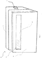
- Fig.1 depicts a portable, hand held, battery operated, device 10 for observation of the visual signal of a chemical indicator.
- the device comprises a body 14.
- the body 14 is sized and shaped to be readily held in the individual user's hand.
- the body 14 comprises an on/off switch 18 that activates the illumination feature (not shown) of the device 10.
- the device 10 further comprises a shield 20.
- the shield 20 removably attaches to the body 14.
- the removable shield 20 comprises an aperture 22.
- This aperture 22 is sized and shaped to receive a window 26.
- This window 26 may be comprised of glass, plastic, mica, any polymer, or other composite material known to those of ordinary skill in the art.
- the window 26 may be either clear or opaque.
- the window may be colored.
- the window 26 is permanently affixed to the shield 20.
- the shield 20 is removable from the body 14.
- multiple shields 20 may be used, with each shield 20 possessing a window 26 of a different color.
- This example permits the user to substitute windows 26 with different colors by attaching different shields 20 to the body 14.
- the power source in the example depicted in Fig.1 is a battery, the power source could be alternating current from a conventional wall socket, a solar panel or any other power source known to those of ordinary skill in the art.
- the shield 20 is permanently affixed to the body 10.
- the window 26 is removably attached to the shield 20. This permits the user to use windows 26 of different colors by removing the window 26 currently in place and substituting a window 26 of the desired color.
- Fig. 2 depicts an exploded view of the device 10.
- the body 14 comprises at least one test tube housing 40.
- the at least one test tube housing 40 is more or less hollow and comprises wells 34 sized and shaped to receive test tubes 38.
- the test tubes 38 comprise lips at their open ends that are larger in diameter than the diameter of the wells 34. When the test tubes 38 are inserted into the wells 34, the lips prevent the test tubes 38 from transiting all the way through the well 34.
- the test tube housing 40 and wells 34 provide a structure to suspend and maintain the test tubes in the proper position to be illuminated and viewed by the observer.
- the test tube housing 40 comprises an opening 30 that permits a view into the interior of the test tube housing 40.
- the opening 30 is located so as to align with the aperture 22 in the shield 20 such the user is afforded a clear view into the interior of the test tubes housing 40.
- the aperture 22 as well as the opening 30 are situated such that at least a portion of the test tubes 38 are visible to the viewer so that the viewer, when looking through the window views the test tubes 38 from a more or less side view or more or less perpendicularly with respect to the long axis of the test tubes 38.
- At least one test tube 38 may be suspended and held into position by clips, brackets or any other means known to those of ordinary skill in the art. Such an example would not require the test tube housing 40 and opening 30 and would allow the test tubes 38 to be viewed directly through the aperture.
- Fig.3 depicts a cutaway view of the body 14 that provides a view of the electronic architecture of the device 10.
- the body comprises a circuit board 44 in electrical communication with the switch 18.
- the electronic architecture further comprises a power source 48 in electrical communication 50 with the switch 18 such that when the switchl8 is engaged, power flows from the power source 48 to the circuit board 44.
- the circuit board 44 comprises sockets 45 into which at least one illuminating device 46 may be inserted.
- the illuminating device 46 may be a light bulb, a light emitting diode, or any other illuminating device familiarto those of ordinary skill in the art.
- the at least one illuminating device 46 illuminates the test tubes 38.
- the circuit board 44 and the at least one illuminating device 46 are located below the wells 34 such that when the test tubes 38 are suspended into the interior of the test tube housing 40, the at least one illuminating device illuminates the test tube from below the test tube. This results in the viewer viewing the test tubes through the aperture and the opening at a more or less right angle to the direction of the light emitted from the at least one illuminating device 46.
- the color of the emitted light may be altered by changing the type of the illuminating device 46. This may be accomplished by replacing the one or more individual illuminating devices 46 in the circuit board.
- the circuit board could comprise illuminating devices 46 of different colors that are selectable by the user. This may be accomplished, for example by connecting all illuminating devices 46 of one color to an individual circuit within the circuit board and allowing the user to power one or more circuits that activate the illuminating devices that will produce the desired and specific color chemical indication.
- the aperture 22 as well as the opening 30 are situated such that the observer, when looking through the window views the test tubes from an angle of 70 degrees or more respect to the angle of the light.
- the aperture 22 as well as the opening 30 are situated such that the observer, when looking through the window views the test tubes from an angle of 60 degrees or more with respect to the angle of the light.
- the aperture 22 as well as the opening 30 are situated such that the observer, when looking through the window views the test tubes from an angle of 50 degrees or more with respect to the angle of the light.
- the aperture 22 as well as the opening 30 are situated such that the observer, when looking through the window views the test tubes from an angle of 40 degrees or more with respect to the angle of the light.
- the aperture 22 as well as the opening 30 are situated such that the observer, when looking through the window views the test tubes from an angle of 30 degrees or more with respect to the angle of the light.
- the aperture 22 as well as the opening 30 are situated such that the observer, when looking through the window views the test tubes from an angle of 20 degrees or more with respect to the angle of the light.
- the aperture 22 as well as the opening 30 are situated such that the observer, when looking through the window views the test tubes from an angle of 10 degrees or more with respect to the angle of the light.
- the aperture 22 as well as the opening 30 are situated such that the observer, when looking through the window views the test tubes from an angle of 5 degrees or more with respect to the angle of the light.
- the aperture 22 as well as the opening 30 are situated such that the observer, when looking through the window views the test tubes from an angle of 1 degree or more with respect to the angle of the light.
- the device comprises a set of heat blocks 58 located proximal to the test tubes 38, so as to be in thermal communication with the test tubes 38.
- the heat blocks 58 are in electrical communication with the circuit board 44 such that when the circuit board 44 is powered, the heat blocks 58 are powered.
- the electrical connection 50 between the heat blocks 58 and the power source 48 may have have at least one resistor 59 or some other device known to those of ordinary skill in the art capable of reducing the current to one or more heat blocks 58 such that the current supplied to the heat block on one side of the test tube is greater than the current supplied to the heat block 58 on the other side of the other side of the test tube.
- This difference in current causes a temperature differential between the heat blocks 58 sufficient to create a convection current within the test tube.
- the heat blocks 58 conform more or less to the shape of the test tubes 38 so as to provide a uniform heat transfer between the heat blocks 58 and the test tubes 38.
- the device 10 comprises a circuit board 44 to adjust the temperatures of the heat blocks.
- one or more rheostats may be included within the circuitry between the power source and the heat blocks 58 so that the temperature of one or more of the heat blocks 58 maybe changed.
- the temperature may also be controlled byanyother device or combination of devices known to those of ordinary skill in the art.
- the device 10 may have a heating element and/or a cooling element such that the device can be made to thermocycle within a set temperature range.
- the device does not possess an internal light source, but rather comprises an opening into the interior of the body. This opening may be in the back or in the bottom of the device 10.
- the open portion is sized and shaped to allow illumination from a light source external the device 10 to enter the device 10 and illuminate the test tubes 38.
- the device possesses a light sensitive meter that registers the wavelength of the light that is emitted from the test tube.
- the light sensitive meter is in electrical communication with a processor capable of executing a machine readable code that converts the registered wavelength into a digital format.
- This digitized data may then be stored in memory device that is in electrical communication with the processor.
- the digitized data may also be displayed in an output device that is in electrical communication with the processor and/or the memory device.
- the aperture 22 in the shield 20 does not comprise a window 26.
- the viewer uses a light filter external to the device to make the indicator visible.
- the light filter may comprise glasses with lenses of an appropriate color.
- the light source is located to the side of the test tubes 38 and the viewing aperture is located above the test tubes 38. In another embodiment, the light source is located to the side of the test tubes 38 and the viewing aperture is located below the test tubes 38. In another embodiment, the light source is located more or less above the test tubes 38 and the viewing aperture 22 is located to the side of the test tubes 38.
- the test tube wells 34 are arranged in at least two rows, staggered. As depicted in Fig. 5 , the test tube wells 34 are arranged in a first row 64 and a second row 60. The test tube wells 34 are arranged in a staggered formation such that the test tubes 38 in the second row 60 are not blocked by the test tubes 38 in the first row 64 from the viewer looking through the aperture.
- windows 68 of varying colors are incorporated into a continuous belt mechanism 70 within the device 10.
- the belt mechanism 70 is stretched between two rotatable wheels 72.
- One of the rotatable wheels is affixed to a actuator wheel 76.
- the actuator wheel 76 As the actuator wheel 76 is rotated, it causes the belt mechanism to move, which in turn, causes the windows 68 of varying colors to move between at least one rotatable wheel 72.
- the user may vary the colors of the windows 68 by manipulating the actuatorwheel 76 until the window of the desired color appears in front of the aperture 22.
- windows 68 of different colors move between the rotatable wheels, they move past the aperture 22 in succession.
- Fig 6 depicts a cover 80 attached at the upper portion of the device 10.
- the cover 80 is configured in such a manner as to block at least a portion of the ambient light.
- the device 10 is too large to be readily hand held.
Landscapes
- Health & Medical Sciences (AREA)
- Chemical & Material Sciences (AREA)
- Physics & Mathematics (AREA)
- Life Sciences & Earth Sciences (AREA)
- Biochemistry (AREA)
- General Health & Medical Sciences (AREA)
- Analytical Chemistry (AREA)
- Immunology (AREA)
- Chemical Kinetics & Catalysis (AREA)
- General Physics & Mathematics (AREA)
- Pathology (AREA)
- Clinical Laboratory Science (AREA)
- Spectroscopy & Molecular Physics (AREA)
- Nuclear Medicine, Radiotherapy & Molecular Imaging (AREA)
- Molecular Biology (AREA)
- Apparatus Associated With Microorganisms And Enzymes (AREA)
- Investigating, Analyzing Materials By Fluorescence Or Luminescence (AREA)
- Investigating Or Analysing Materials By Optical Means (AREA)
- Organic Chemistry (AREA)
- Proteomics, Peptides & Aminoacids (AREA)
- Wood Science & Technology (AREA)
- Engineering & Computer Science (AREA)
- Zoology (AREA)
- Investigating Or Analysing Materials By The Use Of Chemical Reactions (AREA)
- Non-Portable Lighting Devices Or Systems Thereof (AREA)
- Biotechnology (AREA)
- Biophysics (AREA)
- Devices For Use In Laboratory Experiments (AREA)
- General Engineering & Computer Science (AREA)
- Bioinformatics & Cheminformatics (AREA)
- Microbiology (AREA)
- Genetics & Genomics (AREA)
- Spectrometry And Color Measurement (AREA)
- Automatic Analysis And Handling Materials Therefor (AREA)
Applications Claiming Priority (2)
| Application Number | Priority Date | Filing Date | Title |
|---|---|---|---|
| US201261665584P | 2012-06-28 | 2012-06-28 | |
| PCT/US2013/048750 WO2014005112A1 (en) | 2012-06-28 | 2013-06-28 | A chemical indicator device |
Publications (3)
| Publication Number | Publication Date |
|---|---|
| EP2867652A1 EP2867652A1 (en) | 2015-05-06 |
| EP2867652A4 EP2867652A4 (en) | 2016-04-06 |
| EP2867652B1 true EP2867652B1 (en) | 2020-12-09 |
Family
ID=49783929
Family Applications (1)
| Application Number | Title | Priority Date | Filing Date |
|---|---|---|---|
| EP13810528.3A Active EP2867652B1 (en) | 2012-06-28 | 2013-06-28 | A chemical indicator device |
Country Status (15)
| Country | Link |
|---|---|
| US (1) | US11293855B2 (ko) |
| EP (1) | EP2867652B1 (ko) |
| JP (2) | JP6298048B2 (ko) |
| KR (1) | KR102277892B1 (ko) |
| CN (2) | CN104583757A (ko) |
| AU (3) | AU2013282300B2 (ko) |
| BR (1) | BR112014032911A2 (ko) |
| CA (1) | CA2908930C (ko) |
| ES (1) | ES2854987T3 (ko) |
| HK (1) | HK1209829A1 (ko) |
| IL (1) | IL236481A0 (ko) |
| MX (1) | MX350425B (ko) |
| NZ (2) | NZ721632A (ko) |
| RU (2) | RU2643937C2 (ko) |
| WO (1) | WO2014005112A1 (ko) |
Families Citing this family (2)
| Publication number | Priority date | Publication date | Assignee | Title |
|---|---|---|---|---|
| BR112014032911A2 (pt) * | 2012-06-28 | 2017-06-27 | Fluoresentric Inc | dispositivo indicador químico |
| WO2024037302A1 (zh) * | 2022-08-16 | 2024-02-22 | 杭州逸检科技有限公司 | 一种便携式核酸检测设备、系统及方法 |
Citations (1)
| Publication number | Priority date | Publication date | Assignee | Title |
|---|---|---|---|---|
| US20110033899A1 (en) * | 2007-06-14 | 2011-02-10 | Institut Biokhimii I Genetiki Ufimskogo Nauchnogo Tsentra Ran | Convection polymerase chain reaction method |
Family Cites Families (75)
| Publication number | Priority date | Publication date | Assignee | Title |
|---|---|---|---|---|
| CA950703A (en) * | 1970-04-03 | 1974-07-09 | Manuel C. Sanz | Automatic test tube transporter and sample dispenser |
| US5333675C1 (en) | 1986-02-25 | 2001-05-01 | Perkin Elmer Corp | Apparatus and method for performing automated amplification of nucleic acid sequences and assays using heating and cooling steps |
| JPH0515082Y2 (ko) | 1986-04-30 | 1993-04-21 | ||
| US6703236B2 (en) | 1990-11-29 | 2004-03-09 | Applera Corporation | Thermal cycler for automatic performance of the polymerase chain reaction with close temperature control |
| DE4440294A1 (de) | 1994-11-11 | 1996-05-15 | Boehringer Mannheim Gmbh | System zur Inkubation von Probeflüssigkeiten |
| US8293064B2 (en) | 1998-03-02 | 2012-10-23 | Cepheid | Method for fabricating a reaction vessel |
| US5958349A (en) | 1997-02-28 | 1999-09-28 | Cepheid | Reaction vessel for heat-exchanging chemical processes |
| ES2544455T3 (es) | 1997-02-28 | 2015-08-31 | Cepheid | Montaje para reacción química con intercambio de calor, ópticamente interrogada |
| WO1998043740A2 (en) * | 1997-03-28 | 1998-10-08 | The Perkin-Elmer Corporation | Improvements in thermal cycler for pcr |
| US6238869B1 (en) | 1997-12-19 | 2001-05-29 | High Throughput Genomics, Inc. | High throughput assay system |
| US6660228B1 (en) | 1998-03-02 | 2003-12-09 | Cepheid | Apparatus for performing heat-exchanging, chemical reactions |
| US6369893B1 (en) | 1998-05-19 | 2002-04-09 | Cepheid | Multi-channel optical detection system |
| US7188001B2 (en) | 1998-03-23 | 2007-03-06 | Cepheid | System and method for temperature control |
| DE69825142T2 (de) | 1998-05-01 | 2005-08-11 | F. Hoffmann-La Roche Ag | Vorrichtung zur gleichzeitigen Überwachung von Reaktionen, die in einer Vielzahl von Reaktionsgefässen stattfinden |
| US7799521B2 (en) * | 1998-06-24 | 2010-09-21 | Chen & Chen, Llc | Thermal cycling |
| GB9826237D0 (en) * | 1998-11-30 | 1999-01-20 | Hybaid Ltd | Thermal cycler |
| DE19859586C1 (de) | 1998-12-22 | 2000-07-13 | Mwg Biotech Ag | Thermocyclervorrichtung |
| US6818185B1 (en) | 1999-05-28 | 2004-11-16 | Cepheid | Cartridge for conducting a chemical reaction |
| CA2379125C (en) | 1999-07-02 | 2009-04-07 | Clondiag Chip Technologies Gmbh | Microchip matrix device for duplicating and characterizing nucleic acids |
| US6403037B1 (en) | 2000-02-04 | 2002-06-11 | Cepheid | Reaction vessel and temperature control system |
| US7361472B2 (en) * | 2001-02-23 | 2008-04-22 | Invitrogen Corporation | Methods for providing extended dynamic range in analyte assays |
| KR100488281B1 (ko) * | 2001-09-15 | 2005-05-10 | 아람 바이오시스템 주식회사 | 열 대류를 이용한 염기서열 증폭 방법 및 장치 |
| WO2003029397A1 (en) * | 2001-10-02 | 2003-04-10 | Stratagene | Side-wall heater for thermocycler device |
| JP2003344290A (ja) * | 2002-05-27 | 2003-12-03 | Aisin Cosmos R & D Co Ltd | 温度調節付蛍光検出装置 |
| US7238520B2 (en) | 2002-12-04 | 2007-07-03 | Smiths Detection Inc. | PCR sample preparation holder and method |
| US8676383B2 (en) | 2002-12-23 | 2014-03-18 | Applied Biosystems, Llc | Device for carrying out chemical or biological reactions |
| US7049558B2 (en) * | 2003-01-27 | 2006-05-23 | Arcturas Bioscience, Inc. | Apparatus and method for heating microfluidic volumes and moving fluids |
| EP1603674B1 (en) | 2003-02-05 | 2016-01-06 | Iquum, Inc. | Sample processing |
| US7442542B2 (en) | 2003-03-24 | 2008-10-28 | Agency For Science, Technology And Research | Shallow multi-well plastic chip for thermal multiplexing |
| WO2004095009A1 (ja) | 2003-04-24 | 2004-11-04 | Moritex Corporation | 光学検査装置 |
| US20040241048A1 (en) | 2003-05-30 | 2004-12-02 | Applera Corporation | Thermal cycling apparatus and method for providing thermal uniformity |
| US20060194207A1 (en) | 2003-07-30 | 2006-08-31 | Riken | Kit for detecting nucleic acids |
| WO2005116611A2 (en) | 2003-11-05 | 2005-12-08 | Greg Liang | Flow assay device comprising dry reagent cake |
| US8916348B2 (en) | 2004-05-06 | 2014-12-23 | Clondiag Gmbh | Method and device for the detection of molecular interactions |
| TWI392863B (zh) | 2004-08-05 | 2013-04-11 | Universal Bio Research Co Ltd | 反應容器、反應容器液體導入裝置、液體導入反應測定裝置及液體導入裝置 |
| CA2619759A1 (en) | 2005-08-16 | 2007-02-22 | Genentech, Inc. | Apoptosis sensitivity to ap02l/trail by testing for galnac-t14 expression in cells/tissues |
| US20080003564A1 (en) | 2006-02-14 | 2008-01-03 | Iquum, Inc. | Sample processing |
| US20090061450A1 (en) | 2006-03-14 | 2009-03-05 | Micronics, Inc. | System and method for diagnosis of infectious diseases |
| US20080153096A1 (en) | 2006-11-02 | 2008-06-26 | Vectrant Technologies Inc. | Cartridge for conducting diagnostic assays |
| EP2140033B1 (en) | 2007-03-28 | 2012-10-10 | Signal Diagnostics | System and method for high resolution analysis of nucleic acids to detect sequence variations |
| JP5205802B2 (ja) * | 2007-05-11 | 2013-06-05 | ソニー株式会社 | リアルタイムpcr装置 |
| GB0710957D0 (en) | 2007-06-07 | 2007-07-18 | Norchip As | A device for carrying out cell lysis and nucleic acid extraction |
| US8133671B2 (en) | 2007-07-13 | 2012-03-13 | Handylab, Inc. | Integrated apparatus for performing nucleic acid extraction and diagnostic testing on multiple biological samples |
| WO2009018473A1 (en) | 2007-07-31 | 2009-02-05 | Micronics, Inc. | Sanitary swab collection system, microfluidic assay device, and methods for diagnostic assays |
| WO2009072987A1 (en) | 2007-12-06 | 2009-06-11 | Agency For Science, Technology And Research | Integrated apparatus for conducting and monitoring chemical reactions |
| JP5196126B2 (ja) * | 2007-12-10 | 2013-05-15 | セイコーエプソン株式会社 | 生体試料反応装置および生体試料反応方法 |
| US7881594B2 (en) * | 2007-12-27 | 2011-02-01 | Stmicroeletronics, Inc. | Heating system and method for microfluidic and micromechanical applications |
| US9034635B2 (en) | 2008-02-20 | 2015-05-19 | Streck, Inc. | Thermocycler and sample vessel for rapid amplification of DNA |
| US20110097763A1 (en) | 2008-05-13 | 2011-04-28 | Advanced Liquid Logic, Inc. | Thermal Cycling Method |
| DE202008007512U1 (de) * | 2008-06-03 | 2010-11-11 | Levin, Felix, Dr. | Analytisches Vorrichtungssystem zur Bestimmung von Substanzen in Flüssigkeiten |
| US9156010B2 (en) | 2008-09-23 | 2015-10-13 | Bio-Rad Laboratories, Inc. | Droplet-based assay system |
| US8633015B2 (en) | 2008-09-23 | 2014-01-21 | Bio-Rad Laboratories, Inc. | Flow-based thermocycling system with thermoelectric cooler |
| JP5715068B2 (ja) * | 2009-01-30 | 2015-05-07 | マイクロニクス, インコーポレイテッド | 携帯型高利得蛍光検出システム |
| CN104722342B (zh) | 2009-03-24 | 2017-01-11 | 芝加哥大学 | 滑动式芯片装置和方法 |
| WO2010110096A1 (ja) | 2009-03-26 | 2010-09-30 | ユニバーサル・バイオ・リサーチ株式会社 | 反応光学測定装置およびその測定方法 |
| DE212010000039U1 (de) | 2009-04-03 | 2012-02-02 | Helixis, Inc. | Geräte zum erhitzen biologischer proben |
| ES2822105T3 (es) * | 2009-04-15 | 2021-04-29 | Biocartis Nv | Sistema de detección óptica para monitorizar la reacción rtPCR |
| WO2011021640A1 (ja) | 2009-08-20 | 2011-02-24 | タカラバイオ株式会社 | 温度サイクル装置 |
| JP2011232320A (ja) | 2009-10-01 | 2011-11-17 | Sony Corp | 生体内物質検出用プローブ、および該生体内物質検出用プローブを用いた生体内物質検出装置 |
| CN103540517B (zh) * | 2010-07-23 | 2017-05-24 | 贝克曼考尔特公司 | 处理样本的系统及方法 |
| JP2012060912A (ja) | 2010-09-15 | 2012-03-29 | Sony Corp | 核酸増幅反応装置、核酸増幅反応装置に用いる基板、及び核酸増幅反応方法 |
| JP5862006B2 (ja) | 2010-11-17 | 2016-02-16 | セイコーエプソン株式会社 | 熱サイクル装置及び熱サイクル方法 |
| JP5867668B2 (ja) * | 2010-12-01 | 2016-02-24 | セイコーエプソン株式会社 | 熱サイクル装置及び熱サイクル方法 |
| JP5773119B2 (ja) * | 2010-12-14 | 2015-09-02 | セイコーエプソン株式会社 | バイオチップ |
| KR20120107716A (ko) | 2011-03-22 | 2012-10-04 | 삼성테크윈 주식회사 | 시료 보관용 온도 제어 장치 |
| BR112014032911A2 (pt) | 2012-06-28 | 2017-06-27 | Fluoresentric Inc | dispositivo indicador químico |
| EP2882534A4 (en) | 2012-08-07 | 2016-04-13 | California Inst Of Techn | ULTRA FAST THERMOCYCLEUR |
| EP2994543B1 (en) | 2013-05-07 | 2018-08-15 | Micronics, Inc. | Device for preparation and analysis of nucleic acids |
| GB201319759D0 (en) | 2013-11-08 | 2013-12-25 | Thomsen Lars | Device and method for heating a fluid chamber |
| US10191071B2 (en) | 2013-11-18 | 2019-01-29 | IntegenX, Inc. | Cartridges and instruments for sample analysis |
| US9983205B2 (en) | 2014-04-18 | 2018-05-29 | Bio-Rad Laboratories, Inc. | Microfluidic devices for automated assays |
| RU2017103505A (ru) | 2014-07-10 | 2018-08-15 | Флюоресентрик, Инк. | Технология амплификации днк |
| WO2017049230A1 (en) | 2015-09-16 | 2017-03-23 | Fluoresentric, Inc. | Apparatus, systems and methods for dynamic flux amplification of samples |
| EP3402595A4 (en) | 2016-01-11 | 2019-10-02 | Fluoresentric, Inc. | SYSTEMS, APPARATUS AND METHODS FOR PREPARING CONTINUOUS SAMPLES |
| US20220062828A1 (en) * | 2018-09-25 | 2022-03-03 | Evoqua Water Technolgies Llc | Monovalent Selective Cation Exchange Membrane |
-
2013
- 2013-06-28 BR BR112014032911A patent/BR112014032911A2/pt not_active Application Discontinuation
- 2013-06-28 JP JP2015520601A patent/JP6298048B2/ja active Active
- 2013-06-28 CA CA2908930A patent/CA2908930C/en active Active
- 2013-06-28 ES ES13810528T patent/ES2854987T3/es active Active
- 2013-06-28 US US13/931,571 patent/US11293855B2/en active Active
- 2013-06-28 NZ NZ721632A patent/NZ721632A/en not_active IP Right Cessation
- 2013-06-28 NZ NZ704075A patent/NZ704075A/en not_active IP Right Cessation
- 2013-06-28 AU AU2013282300A patent/AU2013282300B2/en active Active
- 2013-06-28 CN CN201380043564.7A patent/CN104583757A/zh active Pending
- 2013-06-28 CN CN201710373338.5A patent/CN107262177B/zh not_active Expired - Fee Related
- 2013-06-28 KR KR1020157002429A patent/KR102277892B1/ko not_active Application Discontinuation
- 2013-06-28 WO PCT/US2013/048750 patent/WO2014005112A1/en active Application Filing
- 2013-06-28 MX MX2015000092A patent/MX350425B/es active IP Right Grant
- 2013-06-28 RU RU2015102527A patent/RU2643937C2/ru not_active IP Right Cessation
- 2013-06-28 EP EP13810528.3A patent/EP2867652B1/en active Active
- 2013-06-28 RU RU2018103106A patent/RU2018103106A/ru not_active Application Discontinuation
-
2014
- 2014-12-25 IL IL236481A patent/IL236481A0/en unknown
-
2015
- 2015-10-19 HK HK15110235.7A patent/HK1209829A1/xx unknown
-
2017
- 2017-06-06 AU AU2017203807A patent/AU2017203807A1/en not_active Abandoned
-
2018
- 2018-02-22 JP JP2018029715A patent/JP6675426B2/ja active Active
-
2019
- 2019-04-09 AU AU2019202449A patent/AU2019202449B2/en active Active
Patent Citations (1)
| Publication number | Priority date | Publication date | Assignee | Title |
|---|---|---|---|---|
| US20110033899A1 (en) * | 2007-06-14 | 2011-02-10 | Institut Biokhimii I Genetiki Ufimskogo Nauchnogo Tsentra Ran | Convection polymerase chain reaction method |
Also Published As
| Publication number | Publication date |
|---|---|
| HK1209829A1 (en) | 2016-04-08 |
| JP2015523075A (ja) | 2015-08-13 |
| NZ704075A (en) | 2016-07-29 |
| NZ721632A (en) | 2017-08-25 |
| JP6298048B2 (ja) | 2018-03-20 |
| US20140026685A1 (en) | 2014-01-30 |
| MX2015000092A (es) | 2015-07-06 |
| AU2013282300B2 (en) | 2017-03-09 |
| WO2014005112A1 (en) | 2014-01-03 |
| KR20150042188A (ko) | 2015-04-20 |
| MX350425B (es) | 2017-09-05 |
| JP6675426B2 (ja) | 2020-04-01 |
| CN104583757A (zh) | 2015-04-29 |
| KR102277892B1 (ko) | 2021-07-15 |
| AU2017203807A1 (en) | 2017-06-22 |
| US11293855B2 (en) | 2022-04-05 |
| CA2908930C (en) | 2021-08-03 |
| EP2867652A1 (en) | 2015-05-06 |
| RU2643937C2 (ru) | 2018-02-06 |
| BR112014032911A2 (pt) | 2017-06-27 |
| IL236481A0 (en) | 2015-02-26 |
| AU2019202449A1 (en) | 2019-05-02 |
| CN107262177A (zh) | 2017-10-20 |
| CN107262177B (zh) | 2020-07-10 |
| ES2854987T3 (es) | 2021-09-23 |
| JP2018088930A (ja) | 2018-06-14 |
| RU2018103106A (ru) | 2019-02-22 |
| CA2908930A1 (en) | 2014-01-03 |
| RU2015102527A (ru) | 2016-08-20 |
| AU2019202449B2 (en) | 2021-02-25 |
| EP2867652A4 (en) | 2016-04-06 |
| AU2013282300A1 (en) | 2015-02-12 |
Similar Documents
| Publication | Publication Date | Title |
|---|---|---|
| EP2945742B1 (en) | Analytic device | |
| EP3658898B1 (en) | Optical signal detection modules and methods | |
| ES2875831T3 (es) | Sistema óptico para reacciones químicas y/o bioquímicas | |
| AU2019202449B2 (en) | A chemical indicator device | |
| BRPI1012522B1 (pt) | sistema ótico de multiplexação e método para detectar componentes de amostra em pelo menos duas câmaras de amostra diferentes | |
| CN106461540A (zh) | 发色团标记样本的自动成像 | |
| CN104764727A (zh) | 一种荧光成像分析系统及其荧光成像分析方法 | |
| ITTO20110567A1 (it) | Cartuccia per analisi biochimiche, sistema per analisi biochimiche e metodo per eseguire un processo biochimico | |
| US20180252646A1 (en) | Optical structure and optical light detection system | |
| CN204556502U (zh) | 一种荧光成像分析系统 | |
| CN105917227B (zh) | 实时定量和终点比色的pcr装置 | |
| ES2852949T3 (es) | Dispositivo de pruebas modular para analizar muestras biológicas | |
| US20140160466A1 (en) | Microplate reader device | |
| US20210362162A1 (en) | Thermal Cycler for DNA Amplification and Real-Time Detection |
Legal Events
| Date | Code | Title | Description |
|---|---|---|---|
| PUAI | Public reference made under article 153(3) epc to a published international application that has entered the european phase |
Free format text: ORIGINAL CODE: 0009012 |
|
| 17P | Request for examination filed |
Effective date: 20150127 |
|
| AK | Designated contracting states |
Kind code of ref document: A1 Designated state(s): AL AT BE BG CH CY CZ DE DK EE ES FI FR GB GR HR HU IE IS IT LI LT LU LV MC MK MT NL NO PL PT RO RS SE SI SK SM TR |
|
| AX | Request for extension of the european patent |
Extension state: BA ME |
|
| DAX | Request for extension of the european patent (deleted) | ||
| RA4 | Supplementary search report drawn up and despatched (corrected) |
Effective date: 20160303 |
|
| RIC1 | Information provided on ipc code assigned before grant |
Ipc: B01L 9/06 20060101ALI20160226BHEP Ipc: G01N 21/29 20060101AFI20160226BHEP Ipc: G01N 21/64 20060101ALI20160226BHEP |
|
| REG | Reference to a national code |
Ref country code: HK Ref legal event code: DE Ref document number: 1209829 Country of ref document: HK |
|
| STAA | Information on the status of an ep patent application or granted ep patent |
Free format text: STATUS: REQUEST FOR EXAMINATION WAS MADE |
|
| STAA | Information on the status of an ep patent application or granted ep patent |
Free format text: STATUS: EXAMINATION IS IN PROGRESS |
|
| 17Q | First examination report despatched |
Effective date: 20180208 |
|
| RIC1 | Information provided on ipc code assigned before grant |
Ipc: G01N 21/64 20060101ALI20200221BHEP Ipc: G01N 21/29 20060101AFI20200221BHEP Ipc: B01L 9/06 20060101ALI20200221BHEP Ipc: B01L 7/00 20060101ALN20200221BHEP |
|
| RIC1 | Information provided on ipc code assigned before grant |
Ipc: B01L 9/06 20060101ALI20200305BHEP Ipc: G01N 21/29 20060101AFI20200305BHEP Ipc: G01N 21/64 20060101ALI20200305BHEP Ipc: B01L 7/00 20060101ALN20200305BHEP |
|
| RIC1 | Information provided on ipc code assigned before grant |
Ipc: B01L 9/06 20060101ALI20200306BHEP Ipc: B01L 7/00 20060101ALN20200306BHEP Ipc: G01N 21/64 20060101ALI20200306BHEP Ipc: G01N 21/29 20060101AFI20200306BHEP |
|
| RIC1 | Information provided on ipc code assigned before grant |
Ipc: G01N 21/29 20060101AFI20200323BHEP Ipc: B01L 7/00 20060101ALN20200323BHEP Ipc: B01L 9/06 20060101ALI20200323BHEP Ipc: G01N 21/64 20060101ALI20200323BHEP |
|
| GRAP | Despatch of communication of intention to grant a patent |
Free format text: ORIGINAL CODE: EPIDOSNIGR1 |
|
| STAA | Information on the status of an ep patent application or granted ep patent |
Free format text: STATUS: GRANT OF PATENT IS INTENDED |
|
| INTG | Intention to grant announced |
Effective date: 20200518 |
|
| GRAS | Grant fee paid |
Free format text: ORIGINAL CODE: EPIDOSNIGR3 |
|
| GRAJ | Information related to disapproval of communication of intention to grant by the applicant or resumption of examination proceedings by the epo deleted |
Free format text: ORIGINAL CODE: EPIDOSDIGR1 |
|
| GRAL | Information related to payment of fee for publishing/printing deleted |
Free format text: ORIGINAL CODE: EPIDOSDIGR3 |
|
| STAA | Information on the status of an ep patent application or granted ep patent |
Free format text: STATUS: EXAMINATION IS IN PROGRESS |
|
| REG | Reference to a national code |
Ref country code: DE Ref legal event code: R079 Ref document number: 602013074655 Country of ref document: DE Free format text: PREVIOUS MAIN CLASS: G01N0021250000 Ipc: G01N0021290000 |
|
| INTC | Intention to grant announced (deleted) | ||
| RIC1 | Information provided on ipc code assigned before grant |
Ipc: G01N 21/29 20060101AFI20200924BHEP Ipc: B01L 7/00 20060101ALN20200924BHEP Ipc: B01L 9/06 20060101ALI20200924BHEP Ipc: G01N 21/64 20060101ALI20200924BHEP |
|
| GRAR | Information related to intention to grant a patent recorded |
Free format text: ORIGINAL CODE: EPIDOSNIGR71 |
|
| STAA | Information on the status of an ep patent application or granted ep patent |
Free format text: STATUS: GRANT OF PATENT IS INTENDED |
|
| RIC1 | Information provided on ipc code assigned before grant |
Ipc: B01L 7/00 20060101ALN20200925BHEP Ipc: G01N 21/29 20060101AFI20200925BHEP Ipc: G01N 21/64 20060101ALI20200925BHEP Ipc: B01L 9/06 20060101ALI20200925BHEP |
|
| GRAA | (expected) grant |
Free format text: ORIGINAL CODE: 0009210 |
|
| STAA | Information on the status of an ep patent application or granted ep patent |
Free format text: STATUS: THE PATENT HAS BEEN GRANTED |
|
| INTG | Intention to grant announced |
Effective date: 20201029 |
|
| AK | Designated contracting states |
Kind code of ref document: B1 Designated state(s): AL AT BE BG CH CY CZ DE DK EE ES FI FR GB GR HR HU IE IS IT LI LT LU LV MC MK MT NL NO PL PT RO RS SE SI SK SM TR |
|
| REG | Reference to a national code |
Ref country code: GB Ref legal event code: FG4D |
|
| REG | Reference to a national code |
Ref country code: AT Ref legal event code: REF Ref document number: 1343933 Country of ref document: AT Kind code of ref document: T Effective date: 20201215 Ref country code: CH Ref legal event code: EP |
|
| REG | Reference to a national code |
Ref country code: DE Ref legal event code: R096 Ref document number: 602013074655 Country of ref document: DE |
|
| REG | Reference to a national code |
Ref country code: IE Ref legal event code: FG4D |
|
| PG25 | Lapsed in a contracting state [announced via postgrant information from national office to epo] |
Ref country code: GR Free format text: LAPSE BECAUSE OF FAILURE TO SUBMIT A TRANSLATION OF THE DESCRIPTION OR TO PAY THE FEE WITHIN THE PRESCRIBED TIME-LIMIT Effective date: 20210310 Ref country code: FI Free format text: LAPSE BECAUSE OF FAILURE TO SUBMIT A TRANSLATION OF THE DESCRIPTION OR TO PAY THE FEE WITHIN THE PRESCRIBED TIME-LIMIT Effective date: 20201209 Ref country code: RS Free format text: LAPSE BECAUSE OF FAILURE TO SUBMIT A TRANSLATION OF THE DESCRIPTION OR TO PAY THE FEE WITHIN THE PRESCRIBED TIME-LIMIT Effective date: 20201209 Ref country code: NO Free format text: LAPSE BECAUSE OF FAILURE TO SUBMIT A TRANSLATION OF THE DESCRIPTION OR TO PAY THE FEE WITHIN THE PRESCRIBED TIME-LIMIT Effective date: 20210309 |
|
| REG | Reference to a national code |
Ref country code: CH Ref legal event code: NV Representative=s name: TR-IP CONSULTING LLC, CH |
|
| REG | Reference to a national code |
Ref country code: AT Ref legal event code: MK05 Ref document number: 1343933 Country of ref document: AT Kind code of ref document: T Effective date: 20201209 |
|
| PG25 | Lapsed in a contracting state [announced via postgrant information from national office to epo] |
Ref country code: BG Free format text: LAPSE BECAUSE OF FAILURE TO SUBMIT A TRANSLATION OF THE DESCRIPTION OR TO PAY THE FEE WITHIN THE PRESCRIBED TIME-LIMIT Effective date: 20210309 Ref country code: LV Free format text: LAPSE BECAUSE OF FAILURE TO SUBMIT A TRANSLATION OF THE DESCRIPTION OR TO PAY THE FEE WITHIN THE PRESCRIBED TIME-LIMIT Effective date: 20201209 Ref country code: SE Free format text: LAPSE BECAUSE OF FAILURE TO SUBMIT A TRANSLATION OF THE DESCRIPTION OR TO PAY THE FEE WITHIN THE PRESCRIBED TIME-LIMIT Effective date: 20201209 |
|
| REG | Reference to a national code |
Ref country code: NL Ref legal event code: MP Effective date: 20201209 |
|
| PG25 | Lapsed in a contracting state [announced via postgrant information from national office to epo] |
Ref country code: NL Free format text: LAPSE BECAUSE OF FAILURE TO SUBMIT A TRANSLATION OF THE DESCRIPTION OR TO PAY THE FEE WITHIN THE PRESCRIBED TIME-LIMIT Effective date: 20201209 Ref country code: HR Free format text: LAPSE BECAUSE OF FAILURE TO SUBMIT A TRANSLATION OF THE DESCRIPTION OR TO PAY THE FEE WITHIN THE PRESCRIBED TIME-LIMIT Effective date: 20201209 |
|
| REG | Reference to a national code |
Ref country code: LT Ref legal event code: MG9D |
|
| PG25 | Lapsed in a contracting state [announced via postgrant information from national office to epo] |
Ref country code: LT Free format text: LAPSE BECAUSE OF FAILURE TO SUBMIT A TRANSLATION OF THE DESCRIPTION OR TO PAY THE FEE WITHIN THE PRESCRIBED TIME-LIMIT Effective date: 20201209 Ref country code: SK Free format text: LAPSE BECAUSE OF FAILURE TO SUBMIT A TRANSLATION OF THE DESCRIPTION OR TO PAY THE FEE WITHIN THE PRESCRIBED TIME-LIMIT Effective date: 20201209 Ref country code: RO Free format text: LAPSE BECAUSE OF FAILURE TO SUBMIT A TRANSLATION OF THE DESCRIPTION OR TO PAY THE FEE WITHIN THE PRESCRIBED TIME-LIMIT Effective date: 20201209 Ref country code: PT Free format text: LAPSE BECAUSE OF FAILURE TO SUBMIT A TRANSLATION OF THE DESCRIPTION OR TO PAY THE FEE WITHIN THE PRESCRIBED TIME-LIMIT Effective date: 20210409 Ref country code: CZ Free format text: LAPSE BECAUSE OF FAILURE TO SUBMIT A TRANSLATION OF THE DESCRIPTION OR TO PAY THE FEE WITHIN THE PRESCRIBED TIME-LIMIT Effective date: 20201209 Ref country code: EE Free format text: LAPSE BECAUSE OF FAILURE TO SUBMIT A TRANSLATION OF THE DESCRIPTION OR TO PAY THE FEE WITHIN THE PRESCRIBED TIME-LIMIT Effective date: 20201209 Ref country code: SM Free format text: LAPSE BECAUSE OF FAILURE TO SUBMIT A TRANSLATION OF THE DESCRIPTION OR TO PAY THE FEE WITHIN THE PRESCRIBED TIME-LIMIT Effective date: 20201209 |
|
| PG25 | Lapsed in a contracting state [announced via postgrant information from national office to epo] |
Ref country code: AT Free format text: LAPSE BECAUSE OF FAILURE TO SUBMIT A TRANSLATION OF THE DESCRIPTION OR TO PAY THE FEE WITHIN THE PRESCRIBED TIME-LIMIT Effective date: 20201209 Ref country code: PL Free format text: LAPSE BECAUSE OF FAILURE TO SUBMIT A TRANSLATION OF THE DESCRIPTION OR TO PAY THE FEE WITHIN THE PRESCRIBED TIME-LIMIT Effective date: 20201209 |
|
| REG | Reference to a national code |
Ref country code: DE Ref legal event code: R097 Ref document number: 602013074655 Country of ref document: DE |
|
| REG | Reference to a national code |
Ref country code: ES Ref legal event code: FG2A Ref document number: 2854987 Country of ref document: ES Kind code of ref document: T3 Effective date: 20210923 |
|
| PG25 | Lapsed in a contracting state [announced via postgrant information from national office to epo] |
Ref country code: IS Free format text: LAPSE BECAUSE OF FAILURE TO SUBMIT A TRANSLATION OF THE DESCRIPTION OR TO PAY THE FEE WITHIN THE PRESCRIBED TIME-LIMIT Effective date: 20210409 |
|
| PLBE | No opposition filed within time limit |
Free format text: ORIGINAL CODE: 0009261 |
|
| STAA | Information on the status of an ep patent application or granted ep patent |
Free format text: STATUS: NO OPPOSITION FILED WITHIN TIME LIMIT |
|
| PG25 | Lapsed in a contracting state [announced via postgrant information from national office to epo] |
Ref country code: AL Free format text: LAPSE BECAUSE OF FAILURE TO SUBMIT A TRANSLATION OF THE DESCRIPTION OR TO PAY THE FEE WITHIN THE PRESCRIBED TIME-LIMIT Effective date: 20201209 |
|
| 26N | No opposition filed |
Effective date: 20210910 |
|
| PG25 | Lapsed in a contracting state [announced via postgrant information from national office to epo] |
Ref country code: DK Free format text: LAPSE BECAUSE OF FAILURE TO SUBMIT A TRANSLATION OF THE DESCRIPTION OR TO PAY THE FEE WITHIN THE PRESCRIBED TIME-LIMIT Effective date: 20201209 Ref country code: SI Free format text: LAPSE BECAUSE OF FAILURE TO SUBMIT A TRANSLATION OF THE DESCRIPTION OR TO PAY THE FEE WITHIN THE PRESCRIBED TIME-LIMIT Effective date: 20201209 |
|
| PG25 | Lapsed in a contracting state [announced via postgrant information from national office to epo] |
Ref country code: MC Free format text: LAPSE BECAUSE OF FAILURE TO SUBMIT A TRANSLATION OF THE DESCRIPTION OR TO PAY THE FEE WITHIN THE PRESCRIBED TIME-LIMIT Effective date: 20201209 |
|
| REG | Reference to a national code |
Ref country code: BE Ref legal event code: MM Effective date: 20210630 |
|
| PG25 | Lapsed in a contracting state [announced via postgrant information from national office to epo] |
Ref country code: LU Free format text: LAPSE BECAUSE OF NON-PAYMENT OF DUE FEES Effective date: 20210628 |
|
| PG25 | Lapsed in a contracting state [announced via postgrant information from national office to epo] |
Ref country code: IE Free format text: LAPSE BECAUSE OF NON-PAYMENT OF DUE FEES Effective date: 20210628 |
|
| PG25 | Lapsed in a contracting state [announced via postgrant information from national office to epo] |
Ref country code: IS Free format text: LAPSE BECAUSE OF FAILURE TO SUBMIT A TRANSLATION OF THE DESCRIPTION OR TO PAY THE FEE WITHIN THE PRESCRIBED TIME-LIMIT Effective date: 20210409 |
|
| PG25 | Lapsed in a contracting state [announced via postgrant information from national office to epo] |
Ref country code: BE Free format text: LAPSE BECAUSE OF NON-PAYMENT OF DUE FEES Effective date: 20210630 |
|
| PG25 | Lapsed in a contracting state [announced via postgrant information from national office to epo] |
Ref country code: HU Free format text: LAPSE BECAUSE OF FAILURE TO SUBMIT A TRANSLATION OF THE DESCRIPTION OR TO PAY THE FEE WITHIN THE PRESCRIBED TIME-LIMIT; INVALID AB INITIO Effective date: 20130628 |
|
| PG25 | Lapsed in a contracting state [announced via postgrant information from national office to epo] |
Ref country code: CY Free format text: LAPSE BECAUSE OF FAILURE TO SUBMIT A TRANSLATION OF THE DESCRIPTION OR TO PAY THE FEE WITHIN THE PRESCRIBED TIME-LIMIT Effective date: 20201209 |
|
| PGFP | Annual fee paid to national office [announced via postgrant information from national office to epo] |
Ref country code: IT Payment date: 20230510 Year of fee payment: 11 Ref country code: FR Payment date: 20230510 Year of fee payment: 11 Ref country code: DE Payment date: 20230502 Year of fee payment: 11 |
|
| PGFP | Annual fee paid to national office [announced via postgrant information from national office to epo] |
Ref country code: GB Payment date: 20230504 Year of fee payment: 11 Ref country code: ES Payment date: 20230712 Year of fee payment: 11 Ref country code: CH Payment date: 20230702 Year of fee payment: 11 |
|
| PG25 | Lapsed in a contracting state [announced via postgrant information from national office to epo] |
Ref country code: MK Free format text: LAPSE BECAUSE OF FAILURE TO SUBMIT A TRANSLATION OF THE DESCRIPTION OR TO PAY THE FEE WITHIN THE PRESCRIBED TIME-LIMIT Effective date: 20201209 |
|
| PG25 | Lapsed in a contracting state [announced via postgrant information from national office to epo] |
Ref country code: TR Free format text: LAPSE BECAUSE OF FAILURE TO SUBMIT A TRANSLATION OF THE DESCRIPTION OR TO PAY THE FEE WITHIN THE PRESCRIBED TIME-LIMIT Effective date: 20201209 |