EP2867589B1 - Evaporative humidifier and indoor climate controlling system comprising the same - Google Patents
Evaporative humidifier and indoor climate controlling system comprising the same Download PDFInfo
- Publication number
- EP2867589B1 EP2867589B1 EP13750737.2A EP13750737A EP2867589B1 EP 2867589 B1 EP2867589 B1 EP 2867589B1 EP 13750737 A EP13750737 A EP 13750737A EP 2867589 B1 EP2867589 B1 EP 2867589B1
- Authority
- EP
- European Patent Office
- Prior art keywords
- evaporative humidifier
- fan
- float
- wick
- unit
- Prior art date
- Legal status (The legal status is an assumption and is not a legal conclusion. Google has not performed a legal analysis and makes no representation as to the accuracy of the status listed.)
- Active
Links
Images

Classifications
-
- F—MECHANICAL ENGINEERING; LIGHTING; HEATING; WEAPONS; BLASTING
- F24—HEATING; RANGES; VENTILATING
- F24F—AIR-CONDITIONING; AIR-HUMIDIFICATION; VENTILATION; USE OF AIR CURRENTS FOR SCREENING
- F24F6/00—Air-humidification, e.g. cooling by humidification
- F24F6/02—Air-humidification, e.g. cooling by humidification by evaporation of water in the air
- F24F6/04—Air-humidification, e.g. cooling by humidification by evaporation of water in the air using stationary unheated wet elements
- F24F6/043—Air-humidification, e.g. cooling by humidification by evaporation of water in the air using stationary unheated wet elements with self-sucking action, e.g. wicks
-
- F—MECHANICAL ENGINEERING; LIGHTING; HEATING; WEAPONS; BLASTING
- F24—HEATING; RANGES; VENTILATING
- F24F—AIR-CONDITIONING; AIR-HUMIDIFICATION; VENTILATION; USE OF AIR CURRENTS FOR SCREENING
- F24F11/00—Control or safety arrangements
- F24F11/0008—Control or safety arrangements for air-humidification
-
- F—MECHANICAL ENGINEERING; LIGHTING; HEATING; WEAPONS; BLASTING
- F24—HEATING; RANGES; VENTILATING
- F24F—AIR-CONDITIONING; AIR-HUMIDIFICATION; VENTILATION; USE OF AIR CURRENTS FOR SCREENING
- F24F13/00—Details common to, or for air-conditioning, air-humidification, ventilation or use of air currents for screening
- F24F13/02—Ducting arrangements
- F24F13/06—Outlets for directing or distributing air into rooms or spaces, e.g. ceiling air diffuser
-
- F—MECHANICAL ENGINEERING; LIGHTING; HEATING; WEAPONS; BLASTING
- F24—HEATING; RANGES; VENTILATING
- F24F—AIR-CONDITIONING; AIR-HUMIDIFICATION; VENTILATION; USE OF AIR CURRENTS FOR SCREENING
- F24F6/00—Air-humidification, e.g. cooling by humidification
- F24F2006/008—Air-humidifier with water reservoir
Definitions
- the present invention relates generally to an evaporative humidifier and an indoor climate controlling system using such an evaporative humidifier.
- a humidifier is an appliance that increases humidity (moisture) in a single room or in an entire house.
- the most commonly used humidifier is an evaporative or wick humidifier including a water reservoir, a wick immersed in water and a fan adjacent to the wick.
- the reservoir is a containing tank of water filled prior to and/or during operation and provides water for a moisture output.
- the wick is a water screen, a water absorbing medium or a filter that absorbs water from the reservoir.
- the fan creates an air flow which passes through the wick and carries moisture into the room, thus aiding in the evaporation of the water within the wick and the enhancement of humidity.
- a traditional evaporative humidifier usually includes a large fan arranged in a fan housing and corresponding large-area grilles extending almost entirely over a rotary plane of the fan for redirecting the humidified air out of the humidifier.
- This traditional evaporative humidifier has a disadvantage of not allowing for a large user interface arrangement since an upper surface of the evaporative humidifier is at large occupied by the grille.
- the large-area grilles or other attempts to redirect the humidified air at an edge of the fan to a middle of the fan will increase the pressure drop of the fan housing, reduce the efficiency of the fan and result in a loud noise of the fan, thus lowering the efficiency rating of the evaporative humidifier.
- US Patent No. 3864437 discloses a humidifier which in its preferred form has a water receptacle which is vertically expandable and collapsible and provided with a float at its upper end connected to the side wall of the receptacle.
- the humidifying means comprises a water absorbing, air permeable member and/or a water slinger driven by an air impeller.
- a shroud forms an air passageway having inlet and outlet openings. At least a portion of the shroud forms the inlet opening and the moisturizing means are supported by the float for vertical movement in accordance with changes in the water level.
- US Patent No. 3864437 thereby discloses a humidifier according to the preamble of claim 1.
- the invention aims at totally or partly overcoming one or more of the drawbacks mentioned above.
- an evaporative humidifier comprising a water reservoir, a wick unit and a fan unit.
- the wick unit is configured to absorb water from the water reservoir.
- the fan unit is arranged within a fan housing and configured to force an air flow to flow through the wick unit.
- the fan housing comprises a top cover unit defining at least one annular air outlet at an outer part adjacent a circumference of the top cover unit. The annular air outlet allows a larger central user interface unit (UI), which could be well received by a user.
- UI central user interface unit
- a bottom wall of the top cover unit has an overall shape of an aerodynamic design for directing air in the fan housing to flow toward the annular air outlet when the fan rotates.
- the aerodynamic design is a streamline design of a convex shape, such as substantially U shape, substantially V shape or substantially trapezoid shape.
- a large-area user interface unit is mounted on the top cover unit and surrounded by the annular air outlet.
- the user can feel the air coming out by his/her wrist, which can be a very convenient way for the user to feel better the strength of the outgoing airflow, alternatively or additionally, he/she can also look at an indicator (e.g., LED) on the UI which gives an visual indication of the strength of the airflow.
- an indicator e.g., LED
- the wick unit comprises a wick, a wick holder for mounting the wick and a float arranged in the wick holder for associating with a water level in the water reservoir and wherein the fan unit comprises a motor and an actuator for actuating the motor, in operation the float is such arranged in the wick holder that the float is guided by the wick holder and buoyed by the water in the water reservoir so that the operation of the evaporative humidifier is controlled based on, at least in part, the water level in the water reservoir.
- the actuator is configured to remain the motor running for a period of time after the water level is below a water level threshold and then stop the motor.
- the actuator may be: a sensor-based actuator, which actuates the motor if the sensed height of the float is up to or higher than a predetermined height; or a contact component, which actuates the motor if the float collides the contacting component.
- the wick and/or the float can be removed from the wick holder for easily cleaning.
- the wick holder forms a substantially vertical guide along which the float is configured to move.
- the float in operation can float a displacement in the range of several millimeters.
- the float clicks into the wick holder.
- the wick holder is heavy enough not to float when it experiences a buoyancy force from the float.
- a humidity sensor for sensing an external air humidity of the room is such arranged on an outer housing of the evaporative humidifier that it is separated from and not interfered by freshly humidified outgoing air.
- the evaporative humidifier further comprises a program control unit configured to ensure that sensing the external air humidity is only performed after the fan unit has been operating for a first period of time and/or the reading of the sensed external air humidity is frozen for a second period of time after the fan unit stops operating so as not to confuse the user by a sharply increment of the reading caused by the humidified air inside the evaporative humidifier.
- the first and/or the second period of time is 10 minutes.
- the program control unit is further configured to automatically actuate the fan unit when the sensed external air humidity is lower than a preset humidity.
- the present invention also provides an indoor climate controlling system comprising the aforementioned evaporative humidifier and a main control unit coupled to the evaporative humidifier, wherein the main control unit is configured to automatically control the operation of the evaporative humidifier.
- an evaporative humidifier 100 according to an embodiment of the present invention comprises an upper portion 110 and a lower portion 120.
- a fan unit 1101 is arranged in the upper portion 110 while a water reservoir 1202 and a wick unit 1201 are arranged in the lower portion 120.
- the wick unit 1201 is configured to absorb water from the water reservoir 1202 and the fan unit 1101 is arranged within a fan housing 1102 and configured to force an air flow to flow through the wick unit 1201.
- the fan unit 1101 includes a fan 11011, an electric motor 11012 and an actuator 1105 for actuating the motor 11012.
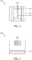
- the fan housing 1102 comprises a top cover unit 1103 defining at least one annular air outlet 1104 at an outer part adjacent a circumference of the top cover unit 1103.
- a bottom wall 11031 of the top cover unit 1103 has an overall shape of an aerodynamic design for directing air in the fan housing 1102, e.g., at the center of the fan housing 1102, to flow toward the annular air outlet 1104 when the fan 11011 rotates.
- the aerodynamic design is a streamline design of a convex shape, such as a substantially U shape, substantially V shape or substantially trapezoid shape.
- a large-area user interface (UI) unit having a UI 1106 and a control circuit 1107 for controlling the display of the UI 1106 is mounted on the top cover unit 1103 and surrounded by the annular air outlet 1104. With this UI 1106 surrounded by the annual air outlet 1104, the user can feel the air coming out by his/her wrist, which can be a very convenient way for the user to feel better the strength of the outgoing airflow, in addition to looking at an indicator (LED) of the UI 1106.
- LED indicator
- the wick unit 1201 comprises a wick 12011, a wick holder 12012 for mounting the wick 12011 and a float 12013 arranged in the wick holder 12012 for associating with a water level in the water reservoir 1202.
- the float 12013 is such arranged in the wick holder 12012 that it is buoyed by the water in the water reservoir 1202 so that the operation of the evaporative humidifier 100 is controlled based on, at least in part, the water level in the water reservoir 1202.
- the wick holder 12012 forms a substantially vertical guide along which the float 12013 is configured to move.
- the actuator 1105 is configured to remain the motor running for a period of time after the water level is below a water level threshold and then stop the motor.
- the actuator 1105 may be: a sensor-based actuator, which actuates the motor if the sensed height of the float is up to or higher than a predetermined height; or a contact component (for instance a contact switch), which actuates the motor 11012 if the float 12013 (for instance its ball-shaped tip portion 12014) collides the contacting component.
- the wick 12011 and/or the float 12013 can be removed from the wick holder 12012 for easily cleaning.
- the float 12013 in operation can float a displacement in the range of several millimeters, for instance 5-100 mm.
- a humidity sensor 150 for sensing an external air humidity out of the humidifier is such arranged on an outer housing 130 of the evaporative humidifier 100 that it is separated from and not interfered by freshly humidified outgoing air.
- the humidity sensor 150 may be arranged in a pathway with one side having small holes to let the external air enter and the other side connected to a negative pressure side of the fan.
- a nonreturn component e.g., a check valve or a nonreturn flap, may be arranged within the pathway for preventing the air flow from returning, thus the humidified air at negative pressure side of the fan will not impact the accurate reading of the sensor.
- the water reservoir 1202 includes an air inlet grille 12021 allowing outer air to flow into the water reservoir 1202 and a viewing window 12022 for user to observe the water level in the water reservoir 1202 straightforward.
- a software algorithm may adopted to ensure that the reading is only displayed/used after the fan has been operating for a fixed period of time. This ensures that unhumidified external air is drawn over the sensor and an accurate reading is provided. If the fan has stopped, the humid air inside the product can cause the reading on the humidity sensor to rise.
- the software can also temporarily freeze the display to prevent the incorrect display of humidity.
- the evaporative humidifier 100 further comprises a program control unit (not shown) configured to ensure that sensing the external air humidity is only performed after the fan unit 1101 has been operating for a first period of time and/or the reading of the sensed external air humidity is frozen for a second period of time after the fan unit 1101 stops operating so as not to confuse the user by a sharply increment of the reading caused by the humidified air inside the evaporative humidifier 100.
- a program control unit (not shown) configured to ensure that sensing the external air humidity is only performed after the fan unit 1101 has been operating for a first period of time and/or the reading of the sensed external air humidity is frozen for a second period of time after the fan unit 1101 stops operating so as not to confuse the user by a sharply increment of the reading caused by the humidified air inside the evaporative humidifier 100.
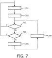
- step 701 the humidity is calculated in step 701 and displayed in step 702.
- Steps 703, 704, 705 and 706 are parts of the program to deal with the rise in humidity that occurs when the fan goes off. More concretely, step 703 performs a function of determining whether the fan is rotated for more than 10 minutes, if so return to the step 701; or else determine whether the humidity is lower than a setting value (step 704), if so return to the step 701, otherwise freeze the display (step 705) and then recalculate the humidity (step 706) and go back step 703.
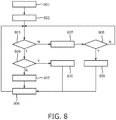
- the program control unit is further configured to automatically actuate the fan unit 1101 when the sensed external air humidity is lower than a preset humidity.
- steps 801-810 are listed in a table 1 below, in which a speed 1 of the fan is larger than the speed 2.
- Table 1 steps functions 801 switch on fan 802 pause for 10 minutes 803 determine whether the calculated humidity is lower than a setting value 804 determine whether a difference between the setting value and the calculated humidity is larger than 7 805 rotate the fan at speed 1 806 pause for 10 minutes 807 switch off the fan 808 determine whether the fan is off for more than 11 minutes 809 rotate the fan at speed 1 810 rotate the fan at speed 2
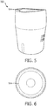
- Figs. 5 and 6 are a finished product view of an evaporative humidifier 500 with an annular air outlet 504. Although the annular air outlet 504 shown in Fig. 5 is continuous, it should be understood that the annular air outlet 504 can be formed discretely or segmented.
- the air out of the evaporative humidifier 100 is firstly sucked with the aid of the fan 11011 or convected into the ourter housing 130 of the evaporative humidifier 100. Most part of the air can then flow through the wick 12011 and carry humidity (moisture) into the fan housing 1102. Finally, the humidified air is blown through the annular air outlet 1104 with the aid of the aerodynamic design of the bottom wall 11031 of the top cover unit 1103, thus enhancing the humidity of a single room or an entire house.
- the evaporative humidifier 100 has a straight sided fan housing 1102. As the fan 11011 spins it tends to concentrate the airflow at the outer edge of the fan housing 1102 and not in the centre of the fan housing 1102. At the fan housing edge, the air is flowing very fast in an upwards spiral. The optimum exit for the air is therefore the outer edge of the fan 11011 where the air is moving fastest. Thus in this invention a relatively small annular outlet 1104 for efficient air removal is created. The air from the fan 11011 is concentrated in this annular outlet at high exit velocity. This provides the following multiple benefits:
- the word “comprising” does not exclude the presence of elements or steps not listed in a claim or in the description.
- the word “a” or “an” preceding an element does not exclude the presence of a plurality of such elements.
- several of these units can be embodied by one and the same item of hardware or software.
- the usage of the words first, second and third, et cetera does not indicate any ordering. These words are to be interpreted as names.
Landscapes
- Engineering & Computer Science (AREA)
- Chemical & Material Sciences (AREA)
- Combustion & Propulsion (AREA)
- Mechanical Engineering (AREA)
- General Engineering & Computer Science (AREA)
- Air Humidification (AREA)
- Air Conditioning Control Device (AREA)
Applications Claiming Priority (2)
| Application Number | Priority Date | Filing Date | Title |
|---|---|---|---|
| CN2012000887 | 2012-06-28 | ||
| PCT/IB2013/054947 WO2014001952A1 (en) | 2012-06-28 | 2013-06-17 | Evaporative humidifier and indoor climate controlling system comprising the same |
Publications (2)
| Publication Number | Publication Date |
|---|---|
| EP2867589A1 EP2867589A1 (en) | 2015-05-06 |
| EP2867589B1 true EP2867589B1 (en) | 2020-08-05 |
Family
ID=49001016
Family Applications (1)
| Application Number | Title | Priority Date | Filing Date |
|---|---|---|---|
| EP13750737.2A Active EP2867589B1 (en) | 2012-06-28 | 2013-06-17 | Evaporative humidifier and indoor climate controlling system comprising the same |
Country Status (6)
| Country | Link |
|---|---|
| US (1) | US9696050B2 (enExample) |
| EP (1) | EP2867589B1 (enExample) |
| JP (1) | JP6235007B2 (enExample) |
| BR (1) | BR112014032132A2 (enExample) |
| RU (1) | RU2639072C2 (enExample) |
| WO (1) | WO2014001952A1 (enExample) |
Families Citing this family (15)
| Publication number | Priority date | Publication date | Assignee | Title |
|---|---|---|---|---|
| CN105215373A (zh) * | 2014-05-28 | 2016-01-06 | 南京理工大学 | 一种制备耐氧化的贵金属银纳米颗粒的方法 |
| US9476603B2 (en) * | 2014-12-12 | 2016-10-25 | Dong Guan Song Wei Electric Technology Co., Ltd | Heater with humidifying device |
| CN108139110B (zh) * | 2016-05-26 | 2021-05-07 | 皇家飞利浦有限公司 | 用于空气处理设备的加湿模块 |
| CN107461838A (zh) * | 2016-06-06 | 2017-12-12 | 深圳市联创电器实业有限公司 | 从下部进风加湿的塔式风扇 |
| CN107588489A (zh) * | 2016-07-08 | 2018-01-16 | 深圳市联创电器实业有限公司 | 同时从两侧面进风的空调扇 |
| US10006651B1 (en) | 2016-12-11 | 2018-06-26 | David J. Myers | Personal cooling device |
| EP3382293A1 (en) | 2017-03-28 | 2018-10-03 | Koninklijke Philips N.V. | Prevention of microbial growth in a humidifier through phosphate limitation |
| RU180274U1 (ru) * | 2018-03-26 | 2018-06-07 | Волкаст Лимитед | Увлажнитель воздуха |
| KR102153685B1 (ko) * | 2018-11-12 | 2020-09-08 | (주)에스엠전자 | 가습장치 |
| CA3049382C (en) * | 2019-07-09 | 2021-10-19 | Condair Group Ag | Mist humidifier blower methods and systems |
| CN111089377A (zh) * | 2020-02-20 | 2020-05-01 | 成都中邦智能科技有限责任公司 | 静音式正压蒸发加湿器 |
| CN113719939B (zh) * | 2021-10-09 | 2025-09-16 | 爱源(厦门)电子有限公司 | 一种风扇上置的加湿器 |
| CN216844967U (zh) * | 2021-11-02 | 2022-06-28 | 深圳秒新科技有限公司 | 加湿器 |
| CN115264699A (zh) * | 2022-07-29 | 2022-11-01 | 珠海格力电器股份有限公司 | 一种蒸发式加湿器 |
| CN117628612A (zh) * | 2022-08-15 | 2024-03-01 | 广东美的环境电器制造有限公司 | 加湿净化器 |
Family Cites Families (23)
| Publication number | Priority date | Publication date | Assignee | Title |
|---|---|---|---|---|
| US3864437A (en) * | 1970-11-16 | 1975-02-04 | Henry Blaszkowski | Humidifier |
| JPS505462U (enExample) * | 1973-05-09 | 1975-01-21 | ||
| JPS54114343U (enExample) * | 1978-01-31 | 1979-08-11 | ||
| JPS59113137U (ja) * | 1983-01-20 | 1984-07-31 | 三洋電機株式会社 | 加湿器 |
| US4822533A (en) * | 1986-12-11 | 1989-04-18 | Emerson Electric Co. | Humidifier with floating wick assembly and replaceable wick elements |
| US5034162A (en) * | 1990-04-17 | 1991-07-23 | Duracraft Corporation | High capacity portable humidifier |
| CA2044023A1 (en) | 1990-10-17 | 1992-04-18 | Kenneth V. Pepper | Humidifier |
| US5143656A (en) * | 1991-10-28 | 1992-09-01 | Duracraft Corporation | Humidifier with a tamper proof liquid level responsive shut-off |
| US5573713A (en) * | 1995-06-06 | 1996-11-12 | Emerson Electric Co. | Humidifier having multi-stage fans |
| US6427984B1 (en) * | 2000-08-11 | 2002-08-06 | Hamilton Beach/Proctor-Silex, Inc. | Evaporative humidifier |
| JP2002081718A (ja) | 2000-09-11 | 2002-03-22 | Sanyo Electric Co Ltd | 加湿器 |
| US6622993B2 (en) | 2000-10-30 | 2003-09-23 | Hamilton Beach/Proctor-Silex, Inc. | Humidifier including output efficiency and liquid level indicators |
| US6550748B2 (en) * | 2001-05-29 | 2003-04-22 | Emerson Electric Co. | Dry out mechanism for humidifier |
| US6592107B1 (en) * | 2001-07-05 | 2003-07-15 | Raymond Electric (China) Ltd. | Floating portable humidifier |
| US6796550B2 (en) * | 2001-08-14 | 2004-09-28 | Hamilton Beach/Proctor-Silex, Inc. | Humidifier filter servicing and water level indicator |
| US7073782B2 (en) * | 2004-01-09 | 2006-07-11 | Jcs/Thg, Llc | Humidifier |
| JP4476795B2 (ja) * | 2004-12-13 | 2010-06-09 | ダイニチ工業株式会社 | 加湿器 |
| JP4652171B2 (ja) * | 2005-08-25 | 2011-03-16 | ダイニチ工業株式会社 | 加湿器 |
| KR100987833B1 (ko) * | 2006-08-03 | 2010-10-13 | 샤프 가부시키가이샤 | 공기 청정기 |
| WO2009070902A1 (de) * | 2007-12-07 | 2009-06-11 | Plaston Ag | Luftbefeuchter mit zentralöffnung zum befüllen und wasserstandsgeführtem verschlusselement |
| US20110179813A1 (en) * | 2010-01-28 | 2011-07-28 | Champion Cooler Corporation | Evaporative cooler with centrifugal fan |
| JP4854797B2 (ja) | 2010-05-11 | 2012-01-18 | ジョルト株式会社 | プログラムおよび電子機器 |
| US9423141B2 (en) * | 2011-12-01 | 2016-08-23 | Sunbeam Products, Inc. | Console humidifier |
-
2013
- 2013-06-17 RU RU2015102617A patent/RU2639072C2/ru active
- 2013-06-17 EP EP13750737.2A patent/EP2867589B1/en active Active
- 2013-06-17 US US14/410,243 patent/US9696050B2/en active Active
- 2013-06-17 WO PCT/IB2013/054947 patent/WO2014001952A1/en not_active Ceased
- 2013-06-17 BR BR112014032132A patent/BR112014032132A2/pt not_active Application Discontinuation
- 2013-06-17 JP JP2015519403A patent/JP6235007B2/ja active Active
Non-Patent Citations (1)
| Title |
|---|
| None * |
Also Published As
| Publication number | Publication date |
|---|---|
| JP6235007B2 (ja) | 2017-11-22 |
| US20150338119A1 (en) | 2015-11-26 |
| JP2015523537A (ja) | 2015-08-13 |
| RU2015102617A (ru) | 2016-08-20 |
| RU2639072C2 (ru) | 2017-12-19 |
| EP2867589A1 (en) | 2015-05-06 |
| WO2014001952A1 (en) | 2014-01-03 |
| BR112014032132A2 (pt) | 2017-06-27 |
| US9696050B2 (en) | 2017-07-04 |
Similar Documents
| Publication | Publication Date | Title |
|---|---|---|
| EP2867589B1 (en) | Evaporative humidifier and indoor climate controlling system comprising the same | |
| KR102770955B1 (ko) | 가습공기청정기 | |
| CN113518884A (zh) | 空调机的室内机及其控制方法 | |
| CN107036196B (zh) | 加湿净化装置 | |
| KR102087679B1 (ko) | 가습청정장치 | |
| EP3832217B1 (en) | Apparatus for both humidification and air cleaning | |
| CN104395676B (zh) | 蒸发式加湿器及包括该蒸发式加湿器的室内气候控制系统 | |
| EP3163198A1 (en) | Apparatus for both humidification and air cleaning | |
| KR102669898B1 (ko) | 가습공기청정기 | |
| EP3330625B1 (en) | Humidifier | |
| KR20090059725A (ko) | 가습공기청정기의 급수장치 | |
| KR102666234B1 (ko) | 가습공기청정기 | |
| KR20190106085A (ko) | 공기조화기 및 그 제어방법 | |
| JP2014066478A (ja) | 加湿機 | |
| KR102275558B1 (ko) | 에어워셔의 급수 제어 방법 | |
| KR102213126B1 (ko) | 에어워셔의 수위 감지방법 | |
| EP3163194A1 (en) | Apparatus for both humidification and air cleaning | |
| KR20170127604A (ko) | 가습공기청정기 | |
| JP6070538B2 (ja) | 加湿装置 | |
| KR20170105220A (ko) | 가습공기청정기 | |
| JP7442034B2 (ja) | 加湿装置 | |
| KR20250029822A (ko) | 가습공기청정기 | |
| KR20170127317A (ko) | 가습공기청정기 | |
| KR20190105442A (ko) | 가습 공기청정기 및 그 제어방법 | |
| KR102250396B1 (ko) | 에어워셔 |
Legal Events
| Date | Code | Title | Description |
|---|---|---|---|
| PUAI | Public reference made under article 153(3) epc to a published international application that has entered the european phase |
Free format text: ORIGINAL CODE: 0009012 |
|
| 17P | Request for examination filed |
Effective date: 20150128 |
|
| AK | Designated contracting states |
Kind code of ref document: A1 Designated state(s): AL AT BE BG CH CY CZ DE DK EE ES FI FR GB GR HR HU IE IS IT LI LT LU LV MC MK MT NL NO PL PT RO RS SE SI SK SM TR |
|
| AX | Request for extension of the european patent |
Extension state: BA ME |
|
| DAX | Request for extension of the european patent (deleted) | ||
| REG | Reference to a national code |
Ref country code: DE Ref legal event code: R079 Ref document number: 602013071319 Country of ref document: DE Free format text: PREVIOUS MAIN CLASS: F24F0006040000 Ipc: F24F0013060000 |
|
| GRAP | Despatch of communication of intention to grant a patent |
Free format text: ORIGINAL CODE: EPIDOSNIGR1 |
|
| STAA | Information on the status of an ep patent application or granted ep patent |
Free format text: STATUS: GRANT OF PATENT IS INTENDED |
|
| RIC1 | Information provided on ipc code assigned before grant |
Ipc: F24F 6/04 20060101ALI20191220BHEP Ipc: F24F 6/00 20060101ALI20191220BHEP Ipc: F24F 11/00 20180101ALI20191220BHEP Ipc: F24F 13/06 20060101AFI20191220BHEP |
|
| INTG | Intention to grant announced |
Effective date: 20200129 |
|
| RAP1 | Party data changed (applicant data changed or rights of an application transferred) |
Owner name: KONINKLIJKE PHILIPS N.V. |
|
| GRAS | Grant fee paid |
Free format text: ORIGINAL CODE: EPIDOSNIGR3 |
|
| GRAA | (expected) grant |
Free format text: ORIGINAL CODE: 0009210 |
|
| STAA | Information on the status of an ep patent application or granted ep patent |
Free format text: STATUS: THE PATENT HAS BEEN GRANTED |
|
| AK | Designated contracting states |
Kind code of ref document: B1 Designated state(s): AL AT BE BG CH CY CZ DE DK EE ES FI FR GB GR HR HU IE IS IT LI LT LU LV MC MK MT NL NO PL PT RO RS SE SI SK SM TR |
|
| REG | Reference to a national code |
Ref country code: GB Ref legal event code: FG4D |
|
| REG | Reference to a national code |
Ref country code: CH Ref legal event code: EP |
|
| REG | Reference to a national code |
Ref country code: AT Ref legal event code: REF Ref document number: 1299258 Country of ref document: AT Kind code of ref document: T Effective date: 20200815 |
|
| REG | Reference to a national code |
Ref country code: DE Ref legal event code: R096 Ref document number: 602013071319 Country of ref document: DE |
|
| REG | Reference to a national code |
Ref country code: IE Ref legal event code: FG4D |
|
| REG | Reference to a national code |
Ref country code: LT Ref legal event code: MG4D |
|
| REG | Reference to a national code |
Ref country code: NL Ref legal event code: MP Effective date: 20200805 |
|
| REG | Reference to a national code |
Ref country code: AT Ref legal event code: MK05 Ref document number: 1299258 Country of ref document: AT Kind code of ref document: T Effective date: 20200805 |
|
| PG25 | Lapsed in a contracting state [announced via postgrant information from national office to epo] |
Ref country code: PT Free format text: LAPSE BECAUSE OF FAILURE TO SUBMIT A TRANSLATION OF THE DESCRIPTION OR TO PAY THE FEE WITHIN THE PRESCRIBED TIME-LIMIT Effective date: 20201207 Ref country code: SE Free format text: LAPSE BECAUSE OF FAILURE TO SUBMIT A TRANSLATION OF THE DESCRIPTION OR TO PAY THE FEE WITHIN THE PRESCRIBED TIME-LIMIT Effective date: 20200805 Ref country code: FI Free format text: LAPSE BECAUSE OF FAILURE TO SUBMIT A TRANSLATION OF THE DESCRIPTION OR TO PAY THE FEE WITHIN THE PRESCRIBED TIME-LIMIT Effective date: 20200805 Ref country code: ES Free format text: LAPSE BECAUSE OF FAILURE TO SUBMIT A TRANSLATION OF THE DESCRIPTION OR TO PAY THE FEE WITHIN THE PRESCRIBED TIME-LIMIT Effective date: 20200805 Ref country code: AT Free format text: LAPSE BECAUSE OF FAILURE TO SUBMIT A TRANSLATION OF THE DESCRIPTION OR TO PAY THE FEE WITHIN THE PRESCRIBED TIME-LIMIT Effective date: 20200805 Ref country code: NO Free format text: LAPSE BECAUSE OF FAILURE TO SUBMIT A TRANSLATION OF THE DESCRIPTION OR TO PAY THE FEE WITHIN THE PRESCRIBED TIME-LIMIT Effective date: 20201105 Ref country code: GR Free format text: LAPSE BECAUSE OF FAILURE TO SUBMIT A TRANSLATION OF THE DESCRIPTION OR TO PAY THE FEE WITHIN THE PRESCRIBED TIME-LIMIT Effective date: 20201106 Ref country code: LT Free format text: LAPSE BECAUSE OF FAILURE TO SUBMIT A TRANSLATION OF THE DESCRIPTION OR TO PAY THE FEE WITHIN THE PRESCRIBED TIME-LIMIT Effective date: 20200805 Ref country code: BG Free format text: LAPSE BECAUSE OF FAILURE TO SUBMIT A TRANSLATION OF THE DESCRIPTION OR TO PAY THE FEE WITHIN THE PRESCRIBED TIME-LIMIT Effective date: 20201105 Ref country code: HR Free format text: LAPSE BECAUSE OF FAILURE TO SUBMIT A TRANSLATION OF THE DESCRIPTION OR TO PAY THE FEE WITHIN THE PRESCRIBED TIME-LIMIT Effective date: 20200805 |
|
| PG25 | Lapsed in a contracting state [announced via postgrant information from national office to epo] |
Ref country code: IS Free format text: LAPSE BECAUSE OF FAILURE TO SUBMIT A TRANSLATION OF THE DESCRIPTION OR TO PAY THE FEE WITHIN THE PRESCRIBED TIME-LIMIT Effective date: 20201205 Ref country code: LV Free format text: LAPSE BECAUSE OF FAILURE TO SUBMIT A TRANSLATION OF THE DESCRIPTION OR TO PAY THE FEE WITHIN THE PRESCRIBED TIME-LIMIT Effective date: 20200805 Ref country code: RS Free format text: LAPSE BECAUSE OF FAILURE TO SUBMIT A TRANSLATION OF THE DESCRIPTION OR TO PAY THE FEE WITHIN THE PRESCRIBED TIME-LIMIT Effective date: 20200805 Ref country code: NL Free format text: LAPSE BECAUSE OF FAILURE TO SUBMIT A TRANSLATION OF THE DESCRIPTION OR TO PAY THE FEE WITHIN THE PRESCRIBED TIME-LIMIT Effective date: 20200805 |
|
| PG25 | Lapsed in a contracting state [announced via postgrant information from national office to epo] |
Ref country code: DK Free format text: LAPSE BECAUSE OF FAILURE TO SUBMIT A TRANSLATION OF THE DESCRIPTION OR TO PAY THE FEE WITHIN THE PRESCRIBED TIME-LIMIT Effective date: 20200805 Ref country code: CZ Free format text: LAPSE BECAUSE OF FAILURE TO SUBMIT A TRANSLATION OF THE DESCRIPTION OR TO PAY THE FEE WITHIN THE PRESCRIBED TIME-LIMIT Effective date: 20200805 Ref country code: EE Free format text: LAPSE BECAUSE OF FAILURE TO SUBMIT A TRANSLATION OF THE DESCRIPTION OR TO PAY THE FEE WITHIN THE PRESCRIBED TIME-LIMIT Effective date: 20200805 Ref country code: SM Free format text: LAPSE BECAUSE OF FAILURE TO SUBMIT A TRANSLATION OF THE DESCRIPTION OR TO PAY THE FEE WITHIN THE PRESCRIBED TIME-LIMIT Effective date: 20200805 Ref country code: RO Free format text: LAPSE BECAUSE OF FAILURE TO SUBMIT A TRANSLATION OF THE DESCRIPTION OR TO PAY THE FEE WITHIN THE PRESCRIBED TIME-LIMIT Effective date: 20200805 |
|
| REG | Reference to a national code |
Ref country code: DE Ref legal event code: R097 Ref document number: 602013071319 Country of ref document: DE |
|
| PG25 | Lapsed in a contracting state [announced via postgrant information from national office to epo] |
Ref country code: AL Free format text: LAPSE BECAUSE OF FAILURE TO SUBMIT A TRANSLATION OF THE DESCRIPTION OR TO PAY THE FEE WITHIN THE PRESCRIBED TIME-LIMIT Effective date: 20200805 |
|
| PLBE | No opposition filed within time limit |
Free format text: ORIGINAL CODE: 0009261 |
|
| STAA | Information on the status of an ep patent application or granted ep patent |
Free format text: STATUS: NO OPPOSITION FILED WITHIN TIME LIMIT |
|
| PG25 | Lapsed in a contracting state [announced via postgrant information from national office to epo] |
Ref country code: SK Free format text: LAPSE BECAUSE OF FAILURE TO SUBMIT A TRANSLATION OF THE DESCRIPTION OR TO PAY THE FEE WITHIN THE PRESCRIBED TIME-LIMIT Effective date: 20200805 |
|
| 26N | No opposition filed |
Effective date: 20210507 |
|
| PG25 | Lapsed in a contracting state [announced via postgrant information from national office to epo] |
Ref country code: IT Free format text: LAPSE BECAUSE OF FAILURE TO SUBMIT A TRANSLATION OF THE DESCRIPTION OR TO PAY THE FEE WITHIN THE PRESCRIBED TIME-LIMIT Effective date: 20200805 |
|
| PG25 | Lapsed in a contracting state [announced via postgrant information from national office to epo] |
Ref country code: SI Free format text: LAPSE BECAUSE OF FAILURE TO SUBMIT A TRANSLATION OF THE DESCRIPTION OR TO PAY THE FEE WITHIN THE PRESCRIBED TIME-LIMIT Effective date: 20200805 |
|
| PG25 | Lapsed in a contracting state [announced via postgrant information from national office to epo] |
Ref country code: MC Free format text: LAPSE BECAUSE OF FAILURE TO SUBMIT A TRANSLATION OF THE DESCRIPTION OR TO PAY THE FEE WITHIN THE PRESCRIBED TIME-LIMIT Effective date: 20200805 |
|
| REG | Reference to a national code |
Ref country code: CH Ref legal event code: PL |
|
| REG | Reference to a national code |
Ref country code: BE Ref legal event code: MM Effective date: 20210630 |
|
| PG25 | Lapsed in a contracting state [announced via postgrant information from national office to epo] |
Ref country code: LU Free format text: LAPSE BECAUSE OF NON-PAYMENT OF DUE FEES Effective date: 20210617 |
|
| PG25 | Lapsed in a contracting state [announced via postgrant information from national office to epo] |
Ref country code: LI Free format text: LAPSE BECAUSE OF NON-PAYMENT OF DUE FEES Effective date: 20210630 Ref country code: IE Free format text: LAPSE BECAUSE OF NON-PAYMENT OF DUE FEES Effective date: 20210617 Ref country code: CH Free format text: LAPSE BECAUSE OF NON-PAYMENT OF DUE FEES Effective date: 20210630 |
|
| PG25 | Lapsed in a contracting state [announced via postgrant information from national office to epo] |
Ref country code: BE Free format text: LAPSE BECAUSE OF NON-PAYMENT OF DUE FEES Effective date: 20210630 |
|
| PG25 | Lapsed in a contracting state [announced via postgrant information from national office to epo] |
Ref country code: HU Free format text: LAPSE BECAUSE OF FAILURE TO SUBMIT A TRANSLATION OF THE DESCRIPTION OR TO PAY THE FEE WITHIN THE PRESCRIBED TIME-LIMIT; INVALID AB INITIO Effective date: 20130617 |
|
| PG25 | Lapsed in a contracting state [announced via postgrant information from national office to epo] |
Ref country code: CY Free format text: LAPSE BECAUSE OF FAILURE TO SUBMIT A TRANSLATION OF THE DESCRIPTION OR TO PAY THE FEE WITHIN THE PRESCRIBED TIME-LIMIT Effective date: 20200805 |
|
| P01 | Opt-out of the competence of the unified patent court (upc) registered |
Effective date: 20230530 |
|
| REG | Reference to a national code |
Ref country code: DE Ref legal event code: R081 Ref document number: 602013071319 Country of ref document: DE Owner name: VERSUNI HOLDING B.V., NL Free format text: FORMER OWNER: KONINKLIJKE PHILIPS N.V., EINDHOVEN, NL |
|
| REG | Reference to a national code |
Ref country code: GB Ref legal event code: 732E Free format text: REGISTERED BETWEEN 20231214 AND 20231220 |
|
| PG25 | Lapsed in a contracting state [announced via postgrant information from national office to epo] |
Ref country code: MK Free format text: LAPSE BECAUSE OF FAILURE TO SUBMIT A TRANSLATION OF THE DESCRIPTION OR TO PAY THE FEE WITHIN THE PRESCRIBED TIME-LIMIT Effective date: 20200805 |
|
| PG25 | Lapsed in a contracting state [announced via postgrant information from national office to epo] |
Ref country code: MT Free format text: LAPSE BECAUSE OF FAILURE TO SUBMIT A TRANSLATION OF THE DESCRIPTION OR TO PAY THE FEE WITHIN THE PRESCRIBED TIME-LIMIT Effective date: 20200805 |
|
| PGFP | Annual fee paid to national office [announced via postgrant information from national office to epo] |
Ref country code: PL Payment date: 20250605 Year of fee payment: 13 Ref country code: DE Payment date: 20250626 Year of fee payment: 13 |
|
| PGFP | Annual fee paid to national office [announced via postgrant information from national office to epo] |
Ref country code: GB Payment date: 20250617 Year of fee payment: 13 |
|
| PGFP | Annual fee paid to national office [announced via postgrant information from national office to epo] |
Ref country code: FR Payment date: 20250624 Year of fee payment: 13 |
|
| PG25 | Lapsed in a contracting state [announced via postgrant information from national office to epo] |
Ref country code: TR Free format text: LAPSE BECAUSE OF FAILURE TO SUBMIT A TRANSLATION OF THE DESCRIPTION OR TO PAY THE FEE WITHIN THE PRESCRIBED TIME-LIMIT Effective date: 20200805 |