EP2867111B1 - Unterwasserrumpf eines wasserfahrzeuges - Google Patents
Unterwasserrumpf eines wasserfahrzeuges Download PDFInfo
- Publication number
- EP2867111B1 EP2867111B1 EP13741659.0A EP13741659A EP2867111B1 EP 2867111 B1 EP2867111 B1 EP 2867111B1 EP 13741659 A EP13741659 A EP 13741659A EP 2867111 B1 EP2867111 B1 EP 2867111B1
- Authority
- EP
- European Patent Office
- Prior art keywords
- point
- region
- hull
- bow
- underwater hull
- Prior art date
- Legal status (The legal status is an assumption and is not a legal conclusion. Google has not performed a legal analysis and makes no representation as to the accuracy of the status listed.)
- Active
Links
Images


Classifications
-
- B—PERFORMING OPERATIONS; TRANSPORTING
- B63—SHIPS OR OTHER WATERBORNE VESSELS; RELATED EQUIPMENT
- B63B—SHIPS OR OTHER WATERBORNE VESSELS; EQUIPMENT FOR SHIPPING
- B63B1/00—Hydrodynamic or hydrostatic features of hulls or of hydrofoils
- B63B1/02—Hydrodynamic or hydrostatic features of hulls or of hydrofoils deriving lift mainly from water displacement
- B63B1/04—Hydrodynamic or hydrostatic features of hulls or of hydrofoils deriving lift mainly from water displacement with single hull
-
- B—PERFORMING OPERATIONS; TRANSPORTING
- B63—SHIPS OR OTHER WATERBORNE VESSELS; RELATED EQUIPMENT
- B63B—SHIPS OR OTHER WATERBORNE VESSELS; EQUIPMENT FOR SHIPPING
- B63B1/00—Hydrodynamic or hydrostatic features of hulls or of hydrofoils
- B63B1/16—Hydrodynamic or hydrostatic features of hulls or of hydrofoils deriving additional lift from hydrodynamic forces
- B63B1/18—Hydrodynamic or hydrostatic features of hulls or of hydrofoils deriving additional lift from hydrodynamic forces of hydroplane type
- B63B1/20—Hydrodynamic or hydrostatic features of hulls or of hydrofoils deriving additional lift from hydrodynamic forces of hydroplane type having more than one planing surface
-
- B—PERFORMING OPERATIONS; TRANSPORTING
- B63—SHIPS OR OTHER WATERBORNE VESSELS; RELATED EQUIPMENT
- B63B—SHIPS OR OTHER WATERBORNE VESSELS; EQUIPMENT FOR SHIPPING
- B63B1/00—Hydrodynamic or hydrostatic features of hulls or of hydrofoils
- B63B1/02—Hydrodynamic or hydrostatic features of hulls or of hydrofoils deriving lift mainly from water displacement
- B63B1/04—Hydrodynamic or hydrostatic features of hulls or of hydrofoils deriving lift mainly from water displacement with single hull
- B63B1/042—Hydrodynamic or hydrostatic features of hulls or of hydrofoils deriving lift mainly from water displacement with single hull the underpart of which being partly provided with channels or the like, e.g. catamaran shaped
-
- B—PERFORMING OPERATIONS; TRANSPORTING
- B63—SHIPS OR OTHER WATERBORNE VESSELS; RELATED EQUIPMENT
- B63B—SHIPS OR OTHER WATERBORNE VESSELS; EQUIPMENT FOR SHIPPING
- B63B1/00—Hydrodynamic or hydrostatic features of hulls or of hydrofoils
- B63B1/16—Hydrodynamic or hydrostatic features of hulls or of hydrofoils deriving additional lift from hydrodynamic forces
- B63B1/18—Hydrodynamic or hydrostatic features of hulls or of hydrofoils deriving additional lift from hydrodynamic forces of hydroplane type
- B63B1/20—Hydrodynamic or hydrostatic features of hulls or of hydrofoils deriving additional lift from hydrodynamic forces of hydroplane type having more than one planing surface
- B63B2001/203—Hydrodynamic or hydrostatic features of hulls or of hydrofoils deriving additional lift from hydrodynamic forces of hydroplane type having more than one planing surface arranged in semi-catamaran configuration
Definitions
- the invention relates to a watercraft having an underwater hull extending from a bow to a stern.
- Watercraft are generally known and, for example, wind and / or engine operations. Yachts in particular have different designs, in particular on their underwater hull.
- monohull boats in the exemplary embodiment are designed as flat-bottomed boats or multi-body boats, e.g. known as Catamaran or Trimaran.
- the flat bottom boat has become established, whereas the multihull boats are distinguished for best characteristics in terms of achievable top speed with low energy consumption.
- Vessels with displacement hulls and hulls which are not primarily built to carry large loads in the manner of their intended use, ie primarily their own weight and rather low payload, such as persons and / or equipment, must be seen on their main hull in cross-section predominantly a V-shaped configuration, which may be a Knickspant or a round bulkhead.
- the V-shaped configuration of the main frame e.g. straight or curved (concave or convex) ultimately leads to a relatively large displacement over the distance traveled. The energy required for this is growing high 3 to increase speed.
- Watercraft that are built to carry large loads essentially have a flat bottom, similar to the known flat bottom boats. While the last-mentioned "flat bottom vessels" require relatively little energy, but do not have as good driving characteristics, today's conventional displacement and Gleitrümpfe better driving characteristics, but a relatively larger energy needs.
- the invention is based on the object, a watercraft of the type mentioned, such as from the GB2481581 known, in particular its underwater hull, to improve or to provide by simple means, which has low energy consumption in all speed ranges of the vessel with good driving characteristics, and in which the least possible wave formation is generated.
- a vessel having an underwater hull extending from a bow to a stern, which is straight across the longitudinal axis of the vessel, but which has a curve from the bow towards the stern is proposed
- Underwater hull has several, each submerged diving depths, wherein the maximum depth of the underwater hull is reached aft at a distance of about 25% of the total water line from the stern and that the underwater hull has two parallel aligned float elements extending from the bow region, in the axial direction of the underwater hull seen center of the same extend aft.
- the invention thus relates to the design of an underwater ship, which extends from the bow to the stern.
- the underwater vessel consists essentially of a bottom plate, which is led by the bow just above the waterline in several arcs to the maximum depth of the skin rump, and has two floats, which are positioned below this ground, parallel to the longitudinal axis of the ship, positioned between outboard and center longitudinal axis are.
- the swimmers have two tasks. On the one hand, they are to take over the predominant load capacity for the first 2/3 to% of the ship's length. On the other hand, they have a guiding function for the water displaced by the floats to the center of the ship.
- the water displaced to the middle is directed on three sides by the two floats and the bottom plate laid down in several arches, so that close to the center of mass a hydrodynamic effect arises, which is able to lift the ship with increasing speed from the water and thus with increasing Drive to reduce the wetted area.
- the design of the floats determines the total immersion depth.
- the bottom plate extends from the bow area to the stern.
- the bottom plate seen in side view is curved, quasi executed in a flat S-arc, with several, preferably three inflection points and each start or end point and thus several, preferably two immersion depth regions are provided.
- the depth of the main hull part so beneficial in two Diving depth ranges, and is defined by the definition of five points or turning points, by which the contour of the main hull is interpolated.
- the five inflection points define four axial length lengths that represent the design length of the floor slab, which is led from the bow just above the waterline in multiple arcs to the maximum depth of the skin ridge.
- the location of the five points is indicated by the distances on the central axis of the ship and the height to the waterline of the ship at rest.
- WLR describes in the sense of the invention, the assumed waterline at rest during medium voyage of the ship.
- the assumed waterline at rest is determined by the total weight of the ship, which would have to be borne only with the flat bottom plate of the main stocking.
- approximately 1 ⁇ 2 of the total submersion depth of the main hull should be above the assumed waterline.
- given dimensions and values are to be understood as exemplary only.
- a second point or inflection point arranged between the starting point and a third point or inflection point is a height-variable auxiliary point. On the longitudinal axis it is about 9% of the design length of the bottom plate behind (ie seen in the direction of the stern) the starting point.
- the third inflection point is an essential construction point, which lies 1/6 of the construction length of the base plate behind the starting point in its longitudinal distance.
- the altitude or depth is preferably about 40% of the total immersion depth of the main hull.
- a fourth point or inflection point is the design point, which is 1 ⁇ 4 before the end of the design length of the bottom plate on the main axis. It lies in its height on the amount of the diving depth of the main hull.
- the second depth or the second depth of dip is described in the third section.
- the contour of the bottom plate forms a right arc in the interpolation from the third point, which soon changes to a left arc, to get to the fourth point. Due to the slight change in the altitude of the starting point and the second point or inflection point, the naturally occurring inflection point is set by the right arc in a left arc within the third distance so that the naturally occurring inflection point is located in front of the center of gravity of the hull. This is the only way that the resulting hydrodynamic effect can lift the bow area out of the water with increasing speed of the vessel in order to reduce the wetted surface of the main hull with increasing speed.
- An endpoint is at the same height as the fourth point or inflection point at the end of the bottom plate.
- the float elements extend parallel to the longitudinal central axis of the vessel or the underwater vessel.
- two float elements are provided, which are equally spaced on both sides of the central longitudinal axis to this and identical executed.
- the float elements have a bow area, a central area and a stern area. Overall, the float elements on a length, which corresponds to 70% of the total length of the underwater hull.
- the bow portion has an axial length amount of about 20% of the float element length, wherein the rear portion has a length amount of about 25% of the float element length.
- the rear area is thus carried out with respect to the total swimmer length with a greater amount of length than the bow area.
- the central region would suitably have an axial length of about 55% of the float element length.
- the bow region of the respective float element on the bow side is made pointed and widens to form a cylindrically executed body seen in plan view, to which the middle region adjoins.
- the central region is continued with the cylindrically executed body viewed in the direction of the rear area.
- the rear area initially continues the n cylindrical body seen in plan view, and then tapers to a point, so that an end point is oriented towards the stern of the underwater hull.
- Targeting is also when the float elements with their respective central longitudinal axis seen in the transverse direction at a distance from each other, which corresponds to an amount of about 65% of the width of the underwater hull.
- the float elements are at least partially designed as a hollow body, so that for example drives and supplies, but also supply means for the crew and disposal options can be included in the respective float element.
- a drive can be received in each case, wherein both can be coupled together.
- the drive can be done by means of only one of the two drive units until the cruise, which of course also with Both Antriebsagregaten can be done.
- Both drives can each be designed with the smallest possible cubic capacity to meet the potential savings. Since only low speeds are permitted in inland waters, eg on rivers and canals, it is favorable that only one of the two drives is actively switched, wherein both drives can be operated alternately, which can be controlled manually or automatically.
- the float elements are thus advantageously designed so that a water flow guide to the drive screw is present, wherein the water flow velocity is advantageously reduced below the underwater hull and between the float elements by the slimming in the rear of the float element.
- a watercraft which has a small depth with its underwater hull, wherein the float elements spaced as far as the central longitudinal axis but not maximally spaced to this and thus are not located directly on the side edges of the underwater hull, even to a Aufkimmung of the Bottom plate to allow the side wall.
- the float elements end in front of the stern of the vessel, among other things for the reason that there is still sufficient space for the respective drive screw and the rudder system.
- the underwater hull is kept very flat with the invention, wherein in the rear area still a flow guide contour could be provided to the drive screws.
- the underwater hull as a flat bottom at the bow tip just above the waterline (starting point to the second turning point) in a large arc (bulbous) to the third inflection point, ie with the first depth of dip to about 0.4 times (40%) ) of the total immersion depth. From there to about the middle of the float element slimming in the rear area, ie in the second depth range, the underwater hull is guided in a very shallow S-curve on the total immersion depth.
- the float elements advantageously have a multiple function.
- the float elements should fulfill a supporting function.
- the float elements have a water distribution function, so that only half an amount of the displaced water is displaced to the outside, wherein the other half is displaced in the direction of the central longitudinal axis of the underwater hull. This obviously reduces the wave formation to the outside.
- the float elements by slimming in the rear area but also ensure that the water flow velocity is reduced to the drive screws out each, so that the drive screws can provide more effective feed the necessary.
- the float elements in their dimensions with respect to the width and height, ie in the most advantageous width-height ratio with respect to the width of the drives or motors to be installed and with regard to the desired total immersion depth of the vessel to be adjusted.
- the underwater hull is cut or constructed as a flat bottom with the five points, the above-mentioned position of the points should be preferred.
- the lines are chosen so that the underwater hull is guided by an amount of 50% in the middle third of the total length to the total immersion depth, the line being such that it is arranged as uniformly as possible below the center of mass of the vessel.
- the aim of the invention is also the interaction of the float elements with the particularly targeted shaping together with the lines of the underwater hull.
- the cross section of the underwater hull on the main bulkhead can be reduced by 20 to 40%, this cross-sectional amount with the third power (X 3 ) being included in the power calculation, so that the invention results in a watercraft which, in comparison can be operated much cheaper to known positive displacement watercraft.
- watercraft can be equipped with the embodiments of the invention because of the low energy consumption particularly easy with electric motors or with battery-powered and / or solar-powered electric motors.
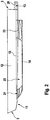
- FIGS. 1 and 2 show an underwater hull 1 of a watercraft, not shown.
- the underwater hull 1 extends from a bow 2 to a stern 3.
- the underwater hull 1 has two parallel aligned float elements 10, which extend from the bow area 11, the same seen in the axial direction of the underwater hull 1 center 12 of the same aft.
- WLR The waterline is identified by reference 13 or WLR.
- WLR describes in the sense of the invention, the assumed waterline at rest during medium voyage of the ship.
- the total immersion depth is designated by the reference numeral 14.
- the bottom plate or the flat bottom 4 extends from the bow portion 11 to the rear 3.
- the bottom plate 4 seen in side view is curved, quasi executed in a flat S-arc, with several, preferably three inflection points P2 to P4 and thus several , preferably two immersion depth regions 5 and 6 are provided.
- the immersion depth 14 of the main hull 1 is therefore advantageously divided into two immersion depth regions 5 and 6, and is defined by the definition of five points P1 to P5 or inflection points P2 to P4, by which the contour of the main hull 1 is interpolated.
- five turning points P1 to P5 four distances A1 to A4 are defined in their axial length, which represent the construction length of the bottom plate 4, which is guided by the bow 2 just above the waterline 13 in multiple arcs to the maximum depth 14 of the skin rump 1.
- the location of the five points P1 to P5 is designated by the distances A1 to A4 on the central axis of the ship and in the height to the waterline 13 of the resting ship.
- the route A1 extends from the starting point P1 to the point P2, the route A2 connecting from point P2 to point P3.
- the distance A3 following the route A2 extends from the point P3 to the point P4, followed by the route A4 ending at the point P5 or at the end point P5.
- WLR describes in the sense of the invention, the assumed waterline 13 at rest during medium voyage of the ship.
- the assumed waterline 13 in the resting state is determined by the total weight of the ship, which would have to be carried by the main hull 1 in flat bottom plate 4 only.
- a second point P2 or inflection point P2 which is arranged between the starting point P1 and a third point P3 or inflection point P3, is at a height variable auxiliary point.
- On the longitudinal axis of this P2 is about 9% of the construction length of the bottom plate 4 behind (so seen in the direction of the rear 3) the starting point P1.
- the third inflection point P3 is an essential construction point, which lies in its longitudinal distance 1/6 of the construction length of the bottom plate 4 behind the starting point P1.
- the altitude or depth is preferably about 40% of the total immersion depth 14 of the main hull. 1
- a fourth point P4 or inflection point P4 is the design point which is% before the end of the design length of the bottom plate 4 on the main axis. It lies in its height at the depth of the diving depth of the main hull 1 determined as described above. Thus, the second diving depth or the second diving depth area 6 is described in the third distance A3.
- the contour of the bottom plate 4 forms in the interpolation from the third point P3 a right arc, which soon changes to a left arc to get to the fourth point P4. Due to the slight change in the altitude of the starting point P1 and the second point P2 or inflection point P2 of naturally occurring inflection point 7 is set by the right arc in a left arc within the third distance A3 so that the naturally occurring inflection point 7 is located in front of the center of gravity of the hull. Only in this way is it possible that the resulting hydrodynamic effect with increasing travel of the watercraft can lift the bow area 11 out of the water, in order to reduce the wetted surface of the main hull 1 as the journey progresses.
- An end point P5 is at the same height as the fourth point P4 or inflection point P4 at the end of the bottom plate 4.
- the float elements extend parallel to the longitudinal central axis of the vessel or of the underwater vessel.
- two float elements are provided, which are equally spaced on both sides of the central longitudinal axis to this and identical executed.
- the float elements 10 have a bow region 21, a central region 22 and a rear region 23. Overall, the float elements 10 have a length, which corresponds to 70% of the total length of the underwater hull 1.
- the bow region 21 has an axial length of about 20% of the float element length, with the tail region 23 having a length amount of about 25% of the float element length.
- the rear region 23 is therefore designed with respect to the total swimmer length with a greater length than the bow region 21.
- the central region 22 would have expediently Axiallyn amount of about 55% of the float element length.
- the bow region 21 of the respective float element 10 is designed to be pointed at the bow end and widens to form a body 24 which is cylindrical in plan view and on which the middle region 22 adjoins.
- the middle region 22 is continued with the cylindrically executed body 24 in the direction of the rear region 23.
- the rear region 23 initially continues the cylindrical body 24 seen in plan view, and then tapers to a point, so that an end tip 25 is oriented towards the stern of the underwater hull 1.
- the float elements 10 have with their respective central longitudinal axis X seen in the transverse direction at a distance 26 to each other, which corresponds to an amount of about 65% of the width 27 of the underwater hull 1.
- the float elements 10 are exemplified so that a water flow guide to the drive screw is present, the water flow velocity is advantageously reduced below the underwater hull 1 and between the float elements 10 by the slimming in the rear portion 23 of the float element.
- the float elements 10 are spaced as far as possible from the central longitudinal axis X but not at a maximum distance from it and thus are not arranged directly on the side edges 28 of the underwater hull 1.
- FIG. 4 It can be seen that the float elements 10, which are cylindrical in plan view, are essentially rectangular, water flow guiding devices still being recognizable. In the figures, eg in FIG. 3 is still an outboard platform 29 recognizable.
Landscapes
- Physics & Mathematics (AREA)
- Fluid Mechanics (AREA)
- Chemical & Material Sciences (AREA)
- Engineering & Computer Science (AREA)
- Combustion & Propulsion (AREA)
- Mechanical Engineering (AREA)
- Ocean & Marine Engineering (AREA)
- Other Liquid Machine Or Engine Such As Wave Power Use (AREA)
Description
- Die Erfindung betrifft ein Wasserfahrzeug, das einen Unterwasserrumpf aufweist, der sich von einem Bug zu einem Heck erstreckt.
- Wasserfahrzeuge sind im Allgemeinen bekannt und beispielsweise Wind- und/oder Motorbetrieben. Insbesondere Yachten weisen unterschiedliche Bauformen insbesondere an ihrem Unterwasserrumpf auf. So sind Einrumpfboote in der beispielhaften Ausgestaltung als Plattbodenschiff oder auch Mehrrumpofboote z.B. als Katamaran oder Trimaran bekannt. Bezüglich der besten Eigenschaft in Bezug auf die Tragfähigkeit bei einem niedrigen Energiebedarf hat sich das Plattbodenschiff etabliert, wohingegen sich die Mehrrumpfboote bezüglich bester Eigenschaften in Bezug auf erreichbare Höchstgeschwindigkeit bei niedrigem Energieverbrauch auszeichnen. Wasserfahrzeuge mit Verdränger- und Gleitrümpfen, die nach Art Ihres Verwendungszweck nicht in erster Linie zum Tragen großer Lasten gebaut werden, also in erster Linie ihr Eigengewicht und eher geringe Zuladung wie Personen und/oder Ausrüstung zu tragen haben, weisen an ihrem Hauptrumpf im Querschnitt gesehen überwiegend eine V-förmige Ausgestaltung auf, wobei es sich um einen Knickspant oder einen Rundspant handeln kann. Die V-förmige Ausgestaltung des Hauptspant z.B. gerade oder gewölbt (konkav oder konvex) führt letztendlich zu einer relativ großen Verdrängung über die gefahrene Strecke. Der dafür nötige Energieaufwand wächst Hoch 3 zur Geschwindigkeitszunahme. Wasserfahrzeuge, die zum Tragen großer Lasten gebaut sind, weisen im wesentlichen einen flachen Boden auf, gleich den bekannten Plattbodenschiffen. Während die zuletzt genannten "Plattbodenschiffe" verhältnismäßig wenig Energie benötigen, dafür aber nicht so gute Fahreigenschaften aufweisen, haben heute übliche Verdränger- und Gleitrümpfe bessere Fahreigenschaften, aber einen relativ größeren Energiebedarf.
- Der Erfindung liegt die Aufgabe zugrunde, ein Wasserfahrzeug der Eingangs genannten Art, wie zum Beispiel aus der
GB2481581 - Erfindungsgemäß wird die Aufgabe durch ein Wasserfahrzeug mit den Merkmalen des Anspruchs 1 gelöst.
- Es ist darauf hinzuweisen, dass die in den Ansprüchen einzeln aufgeführten Merkmale in beliebiger, technisch sinnvoller Weise miteinander kombiniert werden können und weitere Ausgestaltungen der Erfindung aufzeigen. Die Beschreibung charakterisiert und spezifiziert die Erfindung insbesondere im Zusammenhang mit den Figuren zusätzlich.
- Gemäß der Erfindung wird ein Wasserfahrzeug, das einen Unterwasserrumpf aufweist, der sich von einem Bug zu einem Heck erstreckt, vorgeschlagen, welcher quer zur Längsachse des Wasserfahrzeuges gerade ausgeführt ist, der aber einen vom Bug in Richtung zum Heck solchen kurvenförmigen Verlauf aufweist, dass der Unterwasserrumpf mehrere, jeweils in sich übergehende Tauchtiefenbereiche aufweist, wobei die maximale Tauchtiefe des Unterwasserrumpfes achtern in einem Abstand von etwa 25% der Gesamtwasserlinie vom Heck erreicht ist und, dass der Unterwasserrumpf zwei einander parallel ausgerichtete Schwimmerelemente aufweist, welche sich vom Bugbereich, die in Axialrichtung des Unterwasserrumpfes gesehene Mitte desselben übergreifend nach achtern erstrecken. Die Erfindung betrifft also die Gestaltung eines Unterwasserschiffes, das sich vom Bug bis zum Heck erstreckt. Das Unterwasserschiff besteht im wesentlichen aus einer Bodenplatte, die vom Bug knapp oberhalb der Wasserlinie in mehreren Bögen zur maximalen Tauchtiefe des Hautrumpfes geführt wird, und weist zwei Schwimmer auf, die unter diesem Boden angeordnet, parallel zur Längsachse des Schiffes, zwischen Außenbord und Mittellängsachse positioniert sind. Die Schwimmer haben zwei Aufgaben. Zum einen sollen sie die überwiegende Tragleistung für die ersten 2/3 bis % der Schiffslänge übernehmen. Zum anderen, haben sie eine Führungsfunktion für das, durch die Schwimmer zur Schiffsmitte verdrängte Wasser. Das zur Mitte verdrängte Wasser wird an drei Seiten durch die beiden Schwimmer und die in mehreren Bögen niedergeführte Bodenplatte geleitet, so dass nahe des Masseschwerpunktes ein hydrodynamischer Effekt entsteht, der geeignet ist, das Schiff mit zunehmender Fahrt aus dem Wasser zu heben und somit bei zunehmender Fahrt die benetzte Fläche zu reduzieren. Die Gestaltung der Schwimmer bestimmt die Gesamttauchtiefe.
- Die Bodenplatte erstreckt sich vom Bugbereich bis zum Heck. Bei der Erfindung ist die Bodenplatte in Seitenansicht gesehen kurvenförmig, quasi in einem flachen S-Bogen ausgeführt, wobei mehrere, bevorzugt drei Wendepunkte und jeweils Start- bzw. Endpunkt und somit mehrere, bevorzugt zwei Tauchtiefenbereiche vorgesehen sind. Die Tauchtiefe des Hauptrumpfes teil sich also vorteilhaft in zwei Tauchtiefenbereiche auf, und wird durch die Festlegung von fünf Punkten bzw. Wendepunkten definiert, durch die der Konturverlauf des Hauptrumpfes interpoliert wird. Durch die fünf Wendepunkte werden vier Strecken in ihrer axialen Länge definiert, welche die Konstruktionslänge der Bodenplatte darstellen, die vom Bug knapp oberhalb der Wasserlinie in mehreren Bögen zur maximalen Tauchtiefe des Hautrumpfes geführt wird. Die Lage der fünf Punkte wird durch die Strecken auf der Mittelachse des Schiffes und in der Höhe zur Wasserlinie des in Ruhe liegenden Schiffes bezeichnet. Der Begriff WLR beschreibt in Sinne der Erfindung die angenommene Wasserlinie im Ruhezustand bei mittlerer Reise des Schiffes. Die angenommene Wasserlinie im Ruhezustand bestimmt sich aus dem Gesamtgewicht des Schiffes, das bei planebener Bodenplatte einzig vom Hauptrumpf getragen werden müsste. An einem ersten Wendepunkt als Startpunkt der zu interpolierenden Kontur der Bodenplatte sollte etwa ½ der Gesamttauchtiefe des Hauptrumpfes oberhalb der angenommenen Wasserlinie liegen. Selbstverständlich sind angegebene Maße und Werte lediglich beispielhaft zu verstehen. Ein zwischen dem Startpunkt und einem dritten Punkt bzw. Wendepunkt angeordneter zweiter Punkt bzw. Wendepunkt ist ein in der Höhe variabler Hilfspunkt. Auf der Längsachse liegt er etwa 9% der Konstruktionslänge der Bodenplatte hinter (also in Richtung zum Heck gesehen) dem Startpunkt. Der dritte Wendepunkt ist ein Wesentlicher Konstruktionspunkt, der in seinem Längenabstand 1/6 der Konstruktionslänge der Bodenplatte hinter dem Startpunkt liegt. Die Höhenlage bzw. Tiefe beträgt bevorzugt ca. 40% der Gesamttauchtiefe des Hauptrumpfes. Ein vierter Punkt bzw. Wendepunkt ist der Konstruktionspunkt, der sich ¼ vor dem Ende der Konstruktionslänge der Bodenplatte auf der Hauptachse befindet. Er liegt in seiner Höhe auf dem Betrag der Tauchtiefe des Hauptrumpfes. So wird in der dritten Strecke die zweite Tauchtiefe bzw. der zweite Tauchtiefenbereich beschrieben. Der Konturverlauf der Bodenplatte bildet bei der Interpolation ab dem dritten Punkt einen Rechtsbogen, der bald in einen Linksbogen wechselt, um zum vierten Punkt zu gelangen. Durch die geringfügige Veränderung der Höhenlage des Startpunktes und des zweiten Punktes bzw. Wendepunktes wird der natürlich entstehende Wendepunkt vom Rechtsbogen in einen Linksbogen innerhalb der dritten Strecke so eingestellt, dass der natürlich entstehende Wendepunkt vor dem Masseschwerpunkt des Schiffskörpers liegt. Nur so wird es möglich, das der entstehende hydrodynamische Effekt mit zunehmender Fahrt des Wasserfahrzeuges den Bugbereich aus dem Wasser heben kann, um mit zunehmender Fahrt die benetzte Oberfläche des Hauptrumpfes zu reduzieren. Ein Endpunkt liegt auf gleicher Höhe mit dem vierten Punkt bzw. Wendepunkt am Ende der Bodenplatte.
- Zweckmäßiger Weise erstrecken sich die Schwimmerelemente parallel zur Längsmittelachse des Wasserfahrzeuges bzw. des Unterwasserschiffes. In bevorzugter Ausgestaltung sind zwei Schwimmerelemente vorgesehen, welche beidseitig der Mittellängsachse gleich beabstandet zu dieser und identisch ausgeführt sind.
- Die Schwimmerelemente weisen einen Bugbereich, einen Mittelbereich und einen Heckbereich auf. Insgesamt weisen die Schwimmerelemente einen Längebetrag auf, welcher 70% der Gesamtlänge des Unterwasserrumpfes entspricht.
- Zweckmäßig ist, wenn der Bugbereich einen axialen Längenbetrag von etwa 20% der Schwimmerelementlänge aufweist, wobei der Heckbereich einen Längenbetrag von etwa 25% der Schwimmerelementlänge aufweist. Der Heckbereich ist also bezogen auf die Gesamtschwimmerlänge mit einem größeren Längenbetrag ausgeführt als der Bugbereich. Der Mittelbereich hätte zweckdienlich einen Axiallängenbetrag von etwa 55% der Schwimmerelementlänge.
- In bevorzugter Ausführung ist der Bugbereich des jeweiligen Schwimmerelementes bugseitig spitz ausgeführt und erweitert sich zu einem in Aufsicht gesehen zylindrisch ausgeführten Körper an welchem sich der Mittelbereich anschließt. Der Mittelbereich ist mit dem in Aufsicht gesehen zylindrisch ausgeführten Körper in Richtung zum Heckbereich weitergeführt. Der Heckbereich führt den in Aufsicht gesehene n zylindrischen Körper zunächst weiter, und verjüngt sich dann spitz zulaufend, so dass eine Endspitze zum Heck des Unterwasserrumpfes orientiert ist.
- Zielführend ist auch, wenn die Schwimmerelemente mit ihrer jeweiligen Mittellängsachse in Querrichtung gesehen einen Abstand zueinander aufwiesen, welcher einem Betrag von ca. 65 % der Breite des Unterwasserrumpfes entspricht.
- In bevorzugter Ausgestaltung sind die Schwimmerelemente zumindest bereichsweise als Hohlkörper ausgeführt, so dass z.B. Antriebe und Betriebsstoffe, aber auch Versorgungsmittel für die Besatzung und Entsorgungsmöglichkeiten in dem jeweiligen Schwimmerelement aufgenommen werden können. In beiden Schwimmerelementen kann jeweils ein Antrieb aufgenommen werden, wobei beide miteinander koppelbar sind. So kann der Antrieb mittels lediglich einem der beiden Antriebsaggregate bis zur Marschfahrt geschehen, wobei dies natürlich auch mit beiden Antriebsagregaten erfolgen kann. Beide Antriebe können jeweils mit kleinst möglichem Hubraum ausgeführt sein, um dem Einsparpotenzial zu genügen. Da in Binnengewässern, z.B. auf Flüssen und Kanälen nur geringe Geschwindigkeiten zugelassen sind, ist es günstig, dass nur einer der beiden Antriebe aktiv geschaltet ist, wobei beide Antriebe wechselweise betrieben werden können, was manuell oder automatisch steuerbar ist.
- Die Schwimmerelemente sind also vorteilhaft so ausgeführt, dass eine Wasserströmungsführung zur Antriebsschraube vorhanden ist, wobei die Wasserströmungsgeschwindigkeit unterhalb des Unterwasserschiffes und zwischen den Schwimmerelementen durch die Verschlankung im Heckbereich des Schwimmerelementes vorteilhaft reduziert wird.
- Mit der Erfindung wird so ein Wasserfahrzeug geschaffen, welches mit seinem Unterwasserrumpf eine geringe Tauchtiefe aufweist, wobei die Schwimmerelemente möglichst weit beabstandet zur Mittellängsachse aber nicht maximal beabstandet zu dieser und somit nicht direkt an den Seitenrändern des Unterwasserrumpfes angeordnet sind, auch um eine Aufkimmung von der Bodenplatte zur Bordwand zu ermöglichen.
- Die Schwimmerelemente enden vor dem Heck des Wasserfahrzeuges, unter anderen aus dem Grund, dass noch genügend Bauraum für die jeweilige Antriebsschraube und die Ruderanlage vorhanden ist.
- Der Unterwasserrumpf wird mit der Erfindung sehr flach gehalten, wobei im Heckbereich noch eine Strömungsführungskontur zu den Antriebsschrauben vorgesehen werden könnte.
- Günstig ist auch, dass der Unterwasserrumpf als Plattboden an der Bugspitze knapp oberhalb der Wasserlinie (Startpunkt bis zum zweiten Wendepunkt) in einem großen Bogen (bauchig) bis zum dritten Wendepunkt, also mit dem ersten Tauchtiefenbereich bis auf etwa das 0,4fache (40%) der Gesamttauchtiefe geführt wird. Von dort aus bis etwa zur Mitte der Schwimmerelementverschlankung im Heckbereich, also im zweiten Tauchtiefenbereich wird der Unterwasserrumpf in einem sehr flachen S-Bogen auf die Gesamttauchtiefe geführt.
- Die Schwimmerelemente haben vorteilhaft eine Mehrfachfunktion. Zum einen sollen die Schwimmerelemente eine Tragfunktion erfüllen. Zum anderen weisen die Schwimmerelemente eine Wasserteilungsfunktion auf, so dass nur ein hälftiger Betrag des verdrängten Wassers nach außen verdrängt wird, wobei die andere Hälfte in Richtung zur Mittellängsachse des Unterwasserrumpfes verdrängt wird. So wird ersichtlich die Wellenbildung nach außen verringert. Die Schwimmerelemente sorgen durch die Verschlankung im Heckbereich aber auch dafür, dass die Wasserströmungsgeschwindigkeit zu den Antriebsschrauben hin jeweils reduziert wird, so dass die Antriebsschrauben effektiver den notwendigen Vorschub erbringen können. In bevorzugter Ausgestaltung können die Schwimmerelemente in ihren Dimensionen bezüglich der Breite und der Höhe, also im vorteilhaftesten Breite-Höhe-Verhältnis im Hinblick auf die Breite der einzubauenden Antriebe bzw. Motoren und im Hinblick auf die gewünschte Gesamttauchtiefe des Wasserfahrzeuges angepasst werden.
- In besonders zielführender Ausgestaltung wird der Unterwasserrumpf als Plattboden mit den fünf Punkten zugeschnitten bzw. konstruiert, wobei die oben genannte Lage der Punkte bevorzugt werden sollte. Wie bereits erwähnt ist die Linienführung so gewählt, dass der Unterwasserrumpf von einem Betrag von 50% im mittleren Drittel der Gesamtlänge auf die Gesamttauchtiefe geführt wird, wobei die Linienführung so ist, dass diese möglichst gleichmäßig unter dem Massenschwerpunkt des Wasserfahrzeuges angeordnet ist.
- Zielführend bei der Erfindung ist auch das Zusammenwirken der Schwimmerelemente mit der besonders zielführenden Formgebung zusammen mit der Linienführung des Unterwasserrumpfes.
- Je nach Größe des Wasserfahrzeuges kann der Querschnitt des Unterwasserrumpfes auf dem Hauptspant um 20 bis 40% reduziert werden, wobei dieser Querschnittsbetrag mit der dritten Potenz (X3) in die Leistungsberechnung einfließt, so dass sich mit der Erfindung ein Wasserfahrzeug ergibt, welches im Vergleich zu bekannten Verdrängerwasserfahrzeugen deutlich sparsamer betrieben werden kann. Auch können Wasserfahrzeuge mit den erfindungsgemäßen Ausgestaltungen wegen des geringen Energiebedarfs besonders einfach mit Elektromotoren bzw. mit batteriebetriebenen und/oder solarbetriebenen Elektromotoren ausgerüstet werden.
- Vorteilhafte Ausgestaltungen der Erfindung sind in den Unteransprüchen und der folgenden Figurenbeschreibung offenbart. Es zeigen:
-
Fig.1 einen Längsschnitt eines Unterwasserrumpfes eines nicht näher dargestellten Wasserfahrzeuges, -
Fig. 2 eine Seitenansicht des Unterwasserrumpfes ausFigur 1 , -
Fig. 3 eine Aufsicht auf den Unterwasserrumpf ausFigur 1 mit erkennbaren Schwimmerelementen, und -
Fig. 4 eine Heckansicht auf den Unterwasserrumpf. - In den unterschiedlichen Figuren sind gleiche Teile stets mit denselben Bezugszeichen versehen, weswegen diese in der Regel auch nur einmal beschrieben werden.
-
Figuren 1 und2 zeigen einen Unterwasserrumpf 1 eines nicht näher dargestellten Wasserfahrzeuges. Der Unterwasserrumpf 1 erstreckt sich von einem Bug 2 zu einem Heck 3. Vorteilhaft weist der Unterwasserrumpf 1 einen Plattboden 4 auf, der einen vom Bug 2 in Richtung zum Heck 3 solchen kurvenförmigen Verlauf aufweist, dass der Unterwasserrumpf 1 mehrere jeweils in sich übergehende Tauchtiefenbereiche 5 und 6 aufweist, wobei die maximale Tauchtiefe achtern in einem Abstand von etwa 25% der Gesamtwasserlinie vom Heck 3 erreicht ist. Der Unterwasserrumpf 1 weist zwei einander parallel ausgerichtete Schwimmerelemente 10 auf, welche sich vom Bugbereich 11, die in Axialrichtung des Unterwasserrumpfes 1 gesehene Mitte 12 desselben übergreifend nach achtern erstrecken. - Die Wasserlinie ist mit dem Bezugszeichen 13 bzw. WLR gekennzeichnet. Der Begriff WLR beschreibt in Sinne der Erfindung die angenommene Wasserlinie im Ruhezustand bei mittlerer Reise des Schiffes.
- Ein erster Tauchtiefenbereich 5 erstreckt sich vom Bug 2 bauchig verlaufend bis zu einem Tauchtiefenbetrag von etwa 40% der Gesamttauchtiefe des Unterwasserrumpfes 1. Die Gesamttauchtiefe ist mit dem Bezugszeichen 14 bezeichnet.
- Die Bodenplatte bzw. der Plattboden 4 erstreckt sich vom Bugbereich 11 bis zum Heck 3. Bei der Erfindung ist die Bodenplatte 4 in Seitenansicht gesehen kurvenförmig, quasi in einem flachen S-Bogen ausgeführt, wobei mehrere, bevorzugt drei Wendepunkte P2 bis P4 und somit mehrere, bevorzugt zwei Tauchtiefenbereiche 5 und 6 vorgesehen sind.
- Die Tauchtiefe 14 des Hauptrumpfes 1 teil sich also vorteilhaft in zwei Tauchtiefenbereiche 5 und 6 auf, und wird durch die Festlegung von fünf Punkten P1 bis P5 bzw. Wendepunkten P2 bis P4 definiert, durch die der Konturverlauf des Hauptrumpfes 1 interpoliert wird. Durch die fünf Wendepunkte P1 bis P5 werden vier Strecken A1 bis A4 in ihrer axialen Länge definiert, welche die Konstruktionslänge der Bodenplatte 4 darstellen, die vom Bug 2 knapp oberhalb der Wasserlinie 13 in mehreren Bögen zur maximalen Tauchtiefe 14 des Hautrumpfes 1 geführt wird.
- Die Lage der fünf Punkte P1 bis P5 wird durch die Strecken A1 bis A4 auf der Mittelachse des Schiffes und in der Höhe zur Wasserlinie 13 des in Ruhe liegenden Schiffes bezeichnet. Die Strecke A1 erstreckt sich von dem Startpunkt P1 bis zum Punkt P2, wobei sich die Strecke A2 von Punkt P2 bis Punkt P3 anschließt. Die sich an die Strecke A2 anschließende Strecke A3 erstreckt sich von Punkt P3 bis zum Punkt P4, an dem sich die Strecke A4 anschließt, welche an dem Punkt P5 bzw. an dem Endpunkt P5 endet.
- Der Begriff WLR beschreibt in Sinne der Erfindung die angenommene Wasserlinie 13 im Ruhezustand bei mittlerer Reise des Schiffes. Die angenommene Wasserlinie 13 im Ruhezustand bestimmt sich aus dem Gesamtgewicht des Schiffes, das bei planebener Bodenplatte 4 einzig vom Hauptrumpf 1 getragen werden müsste.
- An einem ersten Wendepunkt P1 als Startpunkt P1 der zu interpolierenden Kontur der Bodenplatte 4 sollte etwa ½ der Gesamttauchtiefe 14 des Hauptrumpfes 1 oberhalb der angenommenen Wasserlinie 13 liegen. Selbstverständlich sind alle zuvor und nachfolgend angegebenen Maße und Werte lediglich beispielhaft zu verstehen.
- Ein zwischen dem Startpunkt P1 und einem dritten Punkt P3 bzw. Wendepunkt P3 angeordneter zweiter Punkt P2 bzw. Wendepunkt P2 ist ein in der Höhe variabler Hilfspunkt. Auf der Längsachse liegt dieser P2 etwa 9% der Konstruktionslänge der Bodenplatte 4 hinter (also in Richtung zum Heck 3 gesehen) dem Startpunkt P1.
- Der dritte Wendepunkt P3 ist ein wesentlicher Konstruktionspunkt, der in seinem Längenabstand 1/6 der Konstruktionslänge der Bodenplatte 4 hinter dem Startpunkt P1 liegt. Die Höhenlage bzw. Tiefe beträgt bevorzugt ca. 40% der Gesamttauchtiefe 14 des Hauptrumpfes 1.
- Ein vierter Punkt P4 bzw. Wendepunkt P4 ist der Konstruktionspunkt, der sich % vor dem Ende der Konstruktionslänge der Bodenplatte 4 auf der Hauptachse befindet. Er liegt in seiner Höhe auf der Tiefe der, wie zuvor beschrieben ermittelten Tauchtiefe des Hauptrumpfes 1. So wird in der dritten Strecke A3 die zweite Tauchtiefe bzw. der zweite Tauchtiefenbereich 6 beschrieben.
- Der Konturverlauf der Bodenplatte 4 bildet bei der Interpolation ab dem dritten Punkt P3 einen Rechtsbogen, der bald in einen Linksbogen wechselt, um zum vierten Punkt P4 zu gelangen. Durch die geringfügige Veränderung der Höhenlage des Startpunktes P1 und des zweiten Punktes P2 bzw. Wendepunktes P2 wird der natürlich entstehende Wendepunkt 7 vom Rechtsbogen in einen Linksbogen innerhalb der dritten Strecke A3 so eingestellt, dass der natürlich entstehende Wendepunkt 7 vor dem Masseschwerpunkt des Schiffskörpers liegt. Nur so wird es möglich, das der entstehende hydrodynamische Effekt mit zunehmender Fahrt des Wasserfahrzeuges den Bugbereich 11 aus dem Wasser heben kann, um mit zunehmender Fahrt die benetzte Oberfläche des Hauptrumpfes 1 zu reduzieren. Ein Endpunkt P5 liegt auf gleicher Höhe mit dem vierten Punkt P4 bzw. Wendepunkt P4 am Ende der Bodenplatte 4.
- Die Schwimmerelemente erstrecken sich parallel zur Längsmittelachse des Wasserfahrzeuges bzw. des Unterwasserschiffes. In bevorzugter Ausgestaltung sind zwei Schwimmerelemente vorgesehen, welche beidseitig der Mittellängsachse gleich beabstandet zu dieser und identisch ausgeführt sind.
- Die Schwimmerelemente 10 weisen einen Bugbereich 21, einen Mittelbereich 22 und einen Heckbereich 23 auf. Insgesamt weisen die Schwimmerelemente 10 einen Längebetrag auf, welcher 70% der Gesamtlänge des Unterwasserrumpfes 1 entspricht.
- Beispielhaft weist der Bugbereich 21 einen axialen Längenbetrag von etwa 20% der Schwimmerelementlänge auf, wobei der Heckbereich 23 einen Längenbetrag von etwa 25% der Schwimmerelementlänge aufweist. Der Heckbereich 23 ist also bezogen auf die Gesamtschwimmerlänge mit einem größeren Längenbetrag ausgeführt als der Bugbereich 21. Der Mittelbereich 22 hätte zweckdienlich einen Axiallängenbetrag von etwa 55% der Schwimmerelementlänge.
- Der Bugbereich 21 des jeweiligen Schwimmerelementes 10 ist bugseitig spitz ausgeführt und erweitert sich zu einem in Aufsicht gesehen zylindrisch ausgeführten Körper 24 an welchem sich der Mittelbereich 22 anschließt. Der Mittelbereich 22 ist mit dem in Aufsicht gesehen zylindrisch ausgeführten Körper 24 in Richtung zum Heckbereich 23 weitergeführt. Der Heckbereich 23 führt den in Aufsicht gesehenen zylindrischen Körper 24 zunächst weiter, und verjüngt sich dann spitz zulaufend, so dass eine Endspitze 25 zum Heck des Unterwasserrumpfes 1 orientiert ist.
- Die Schwimmerelemente 10 weisen mit ihrer jeweiligen Mittellängsachse X in Querrichtung gesehen einen Abstand 26 zueinander auf, welcher einem Betrag von ca. 65 % der Breite 27 des Unterwasserrumpfes 1 entspricht.
- Die Schwimmerelemente 10 sind beispielhaft so ausgeführt, dass eine Wasserströmungsführung zur Antriebsschraube vorhanden ist, wobei die Wasserströmungsgeschwindigkeit unterhalb des Unterwasserrumpfes 1 und zwischen den Schwimmerelementen 10 durch die Verschlankung im Heckbereich 23 des Schwimmerelementes vorteilhaft reduziert wird.
- Die Schwimmerelemente 10 sind möglichst weit beabstandet zur Mittellängsachse X aber nicht maximal beabstandet zu dieser und somit nicht direkt an den Seitenrändern 28 des Unterwasserrumpfes 1 angeordnet sind.
- In
Figur 4 ist erkennbar, dass die in Aufsicht gesehen zylindrisch ausgeführten Schwimmerelemente 10 im wesentlichen rechteckig ausgeführt sind, wobei noch Wasserströmungsleitvorrichtungen erkennbar sind. In den Figuren, z.B. inFigur 3 ist noch eine Außenbordplattform 29 erkennbar. -
- 1
- Unterwasserrumpf
- 2
- Bug
- 3
- Heck
- 4
- Plattboden
- 5
- Erster Tauchtiefenbereich
- 6
- Zweiter Tauchtiefenbereich
- 7
- Natürlicher Wendepunkt
- 8 9 10
- Schwimmerelemente
- 11
- Bugbereich von 1
- 12
- Mitte von 1
- 13
- Wasserlinie
- 14
- Gesamttauchtiefe
- 15 16 17 18 19 20 21
- Bugbereich von 10
- 22
- Mittelbereich von 10
- 23
- Heckbereich von 10
- 24
- Zylindrischer Körper
- 25
- Endspitze von 23
- 26
- Abstand
- 27
- Breite von 1
- 28
- Seitenränder von 1
- 29
- Außenbordplattform
Claims (10)
- Wasserfahrzeug, das einen Unterwasserrumpf (1) mit einer Bodenplatte (4) aufweist, der sich von einem Bug (2) zu einem Heck (3) erstreckt, wobei der Unterwasserrumpf (1) in Längsschnitt einen vom Bug (2) in Richtung zum Heck (3) solchen kurvenförmigen Verlauf aufweist, dass der Unterwasserrumpf (1) mehrere jeweils in sich übergehende Tauchtiefenbereiche (5,6) aufweist, wobei die maximale Tauchtiefe (14) achtern in einem Abstand von etwa 25% der Gesamtwasserlinie (13) vom Heck (3) erreicht ist, wobei der Unterwasserrumpf (1) zwei Tauchtiefenbereiche (5,6) und fünf Wendepunkte (P1 bis P5) aufweist, und der Unterwasserrumpf (1) zwei einander parallel ausgerichtete Schwimmerelemente (10) aufweist, welche sich vom Bugbereich, die in Axialrichtung des Unterwasserrumpfes gesehene Mitte (12) desselben übergreifend nach achtern erstrecken,
dadurch gekennzeichnet dass
ein vierter Punkt (P4) bzw. Wendepunkt (P4) sich ¼ vor dem Ende der Konstruktionslänge der Bodenplatte (4) auf der Längsmittelachse befindet, und in seiner Höhe auf der Tiefe der Tauchtiefe des Hauptrumpfes (1) angeordnet ist, wobei in der dritten Strecke (A3) der zweite Tauchtiefenbereich (6) angeordnet ist, wobei der Konturverlauf der Bodenplatte (4) bei der Interpolation ab dem dritten Punkt (P3) einen Rechtsbogen und damit eine Konkavität bildet, der bald in einen Linksbogen und dadurch in einer Konvexität wechselt, um zum vierten Punkt (P4) zu gelangen, wobei durch die geringfügige Veränderung der Höhenlage des Startpunktes (P1) und des zweiten Punktes (P2) bzw. Wendepunktes (P2) ein natürlich entstehende Wendepunkt (7) vom Rechtsbogen in einen Linksbogen innerhalb der dritten Strecke (A3) so eingestellt ist, dass der natürlich entstehende Wendepunkt (7) vor dem Masseschwerpunkt des Schiffskörpers . - Wasserfahrzeug nach Anspruch 1, dadurch gekennzeichnet, dass der Unterwasserrumpf (1) zumindest bereichsweise in einem flachen S-Bogen verläuft.
- Wasserfahrzeug nach Anspruch 1 oder 2, dadurch gekennzeichnet, dass sich ein erster Tauchtiefenbereich (5) vom Bug (2) bauchig verlaufend bis zu einem Tauchtiefenbetrag von etwa 40% der Gesamttauchtiefe (14) des Unterwasserrumpfes (1) erstreckt.
- Wasserfahrzeug nach einem der vorhergehenden Ansprüche, dadurch gekennzeichnet, dass an einem ersten Wendepunkt (P1) als Startpunkt (P1) der Bodenplatte (4) etwa ½ der Gesamttauchtiefe (14) des Hauptrumpfes (1) oberhalb der Wasserlinie (13) liegen.
- Wasserfahrzeug nach einem der vorhergehenden Ansprüche, dadurch gekennzeichnet, dass ein zwischen dem Startpunkt (P1) und einem dritten Punkt (P3) bzw. Wendepunkt (P3) angeordneter zweiter Punkt (P2) bzw. Wendepunkt (P2) auf der Längsachse etwa 9% der Konstruktionslänge der Bodenplatte 4 hinter dem Startpunkt (P1) liegt.
- Wasserfahrzeug nach einem der vorhergehenden Ansprüche, dadurch gekennzeichnet, dass der dritte Wendepunkt (P3) in einem Längenabstand 1/6 der Konstruktionslänge der Bodenplatte (4) hinter dem Startpunkt (P1) liegt, wobei die Höhenlage bzw. Tiefe bevorzugt ca. 40% der Gesamttauchtiefe (14) des Hauptrumpfes (1) beträgt.
- Wasserfahrzeug nach einem der vorhergehenden Ansprüche, dadurch gekennzeichnet, dass die Schwimmerelemente (10) parallel zur Längsmittelachse des Unterwasserrumpfes (1) ausgeführt sind, und beidseitig der Mittellängsachse gleich beabstandet zu dieser und identisch ausgeführt sind.
- Wasserfahrzeug nach einem der vorhergehenden Ansprüche, dadurch gekennzeichnet, dass die Schwimmerelemente (10) einen Bugbereich (21), einen Mittelbereich (22) und einen Heckbereich (23) und einen Längenbetrag aufweisen welcher 70% der Gesamtlänge des Unterwasserrumpfes (1) entspricht.
- Wasserfahrzeug nach einem der vorhergehenden Ansprüche, dadurch gekennzeichnet, dass das jeweilige Schwimmerelement (10) an seinem Bugbereich (21) einen axialen Längenbetrag von etwa 20% der Schwimmerelementlänge aufweist, wobei dessen Heckbereich (23) einen Längenbetrag von etwa 25% der Schwimmerelementlänge aufweist.
- Wasserfahrzeug nach einem der vorhergehenden Ansprüche, dadurch gekennzeichnet, dass ein Bugbereich (21) des jeweiligen Schwimmerelementes (10) bugseitig spitz ausgeführt ist und sich zu einem in Aufsicht gesehen zylindrisch ausgeführten Körper (24) erweitert, an welchem sich ein Mittelbereich (22) anschließt, wobei der Mittelbereich (22) mit dem in Aufsicht gesehen zylindrisch ausgeführten Körper (24) in Richtung zum Heckbereich 23 weitergeführt ist, wobei der Heckbereich (23) den in Aufsicht gesehenen zylindrischen Körper (24) zunächst weiterführt, und sich dann spitz zulaufend verjüngt, so dass eine Endspitze (25) zum Heck des Unterwasserrumpfes (1) orientiert ist.
Applications Claiming Priority (2)
| Application Number | Priority Date | Filing Date | Title |
|---|---|---|---|
| DE202012006183U DE202012006183U1 (de) | 2012-06-27 | 2012-06-27 | Unterwasserrumpf eines Wasserfahrzeuges |
| PCT/DE2013/000323 WO2014000723A1 (de) | 2012-06-27 | 2013-06-17 | Unterwasserrumpf eines wasserfahrzeuges |
Publications (2)
| Publication Number | Publication Date |
|---|---|
| EP2867111A1 EP2867111A1 (de) | 2015-05-06 |
| EP2867111B1 true EP2867111B1 (de) | 2017-03-29 |
Family
ID=46671752
Family Applications (1)
| Application Number | Title | Priority Date | Filing Date |
|---|---|---|---|
| EP13741659.0A Active EP2867111B1 (de) | 2012-06-27 | 2013-06-17 | Unterwasserrumpf eines wasserfahrzeuges |
Country Status (3)
| Country | Link |
|---|---|
| EP (1) | EP2867111B1 (de) |
| DE (2) | DE202012006183U1 (de) |
| WO (1) | WO2014000723A1 (de) |
Family Cites Families (4)
| Publication number | Priority date | Publication date | Assignee | Title |
|---|---|---|---|---|
| US5265554A (en) * | 1992-06-23 | 1993-11-30 | Meredith Marine, Inc. | Boat construction |
| US7578250B2 (en) * | 2005-01-03 | 2009-08-25 | Baker Elbert H | Watercraft with wave deflecting hull |
| FR2890040B1 (fr) * | 2005-08-26 | 2007-10-05 | Dcn Sa | Coque de navire comportant au moins un flotteur |
| GB2481581B (en) * | 2010-06-28 | 2016-07-13 | Pet Mate Ltd | Boat hulls |
-
2012
- 2012-06-27 DE DE202012006183U patent/DE202012006183U1/de not_active Expired - Lifetime
-
2013
- 2013-06-17 WO PCT/DE2013/000323 patent/WO2014000723A1/de active Application Filing
- 2013-06-17 DE DE112013003460.3T patent/DE112013003460A5/de not_active Withdrawn
- 2013-06-17 EP EP13741659.0A patent/EP2867111B1/de active Active
Non-Patent Citations (1)
| Title |
|---|
| None * |
Also Published As
| Publication number | Publication date |
|---|---|
| WO2014000723A1 (de) | 2014-01-03 |
| EP2867111A1 (de) | 2015-05-06 |
| DE112013003460A5 (de) | 2015-03-26 |
| DE202012006183U1 (de) | 2012-07-16 |
Similar Documents
| Publication | Publication Date | Title |
|---|---|---|
| EP0094673B1 (de) | Tragflügelanordnung für einen Katamaran | |
| EP0182314A2 (de) | Katamaran-Luftkissenwasserfahrzeug | |
| EP0358888B1 (de) | Segelyacht | |
| DE202010015531U1 (de) | Wasserfahrzeug | |
| DE2348200A1 (de) | Verdraengungs-hochseeschiff | |
| DE10007497A1 (de) | Wasserfahrzeuge mit vorteilhafter Anwendung der Masse von Niedrigenergiequellen | |
| EP0760773A1 (de) | Rumpf für wasserfahrzeuge, insbesondere segelboote und surfbretter | |
| EP1177129B1 (de) | Kursstabiles, schnelles, seegehendes schiff mit einem für einen ruderpropeller optimierten rumpf | |
| EP2867111B1 (de) | Unterwasserrumpf eines wasserfahrzeuges | |
| WO2022118185A2 (de) | Wasserfahrzeug | |
| CH718114A2 (de) | Wasserfahrzeug. | |
| EP0149855B1 (de) | Rumpf für ein Wasserfahrzeug | |
| DE3801317C2 (de) | ||
| DE10343078A1 (de) | Wasserfahrzeug | |
| EP2769909A2 (de) | Rumpfform und Rumpf eines Wasserfahrzeuges sowie Wasserfahrzeug mit einem Rumpf | |
| DE10134778B4 (de) | Segelboot mit stark eingezogenen Wasserlinien | |
| AT504311B1 (de) | Bootskörper für schnelle wasserfahrzeuge | |
| DE10240534B4 (de) | Schiff | |
| DE3122863A1 (de) | "segelboot" | |
| DE2508377A1 (de) | Ein- oder mehrrumpfsegelboot | |
| DE2647294C3 (de) | Kortdüse für Schiffe | |
| DE102011010962B3 (de) | Segelboot | |
| DE1506204C (de) | Gleitboot mit deltafbrmiger Gleitfläche | |
| DE102009056834A1 (de) | Wasserfahrzeug mit Unterwasserschwimmkörper und Überwassersteuerstand | |
| DE202007015702U1 (de) | Wasserfahrzeug, z.B. Boot |
Legal Events
| Date | Code | Title | Description |
|---|---|---|---|
| PUAI | Public reference made under article 153(3) epc to a published international application that has entered the european phase |
Free format text: ORIGINAL CODE: 0009012 |
|
| 17P | Request for examination filed |
Effective date: 20150108 |
|
| AK | Designated contracting states |
Kind code of ref document: A1 Designated state(s): AL AT BE BG CH CY CZ DE DK EE ES FI FR GB GR HR HU IE IS IT LI LT LU LV MC MK MT NL NO PL PT RO RS SE SI SK SM TR |
|
| AX | Request for extension of the european patent |
Extension state: BA ME |
|
| DAX | Request for extension of the european patent (deleted) | ||
| RIC1 | Information provided on ipc code assigned before grant |
Ipc: B63B 1/20 20060101ALI20161020BHEP Ipc: B63B 1/04 20060101AFI20161020BHEP |
|
| GRAP | Despatch of communication of intention to grant a patent |
Free format text: ORIGINAL CODE: EPIDOSNIGR1 |
|
| STAA | Information on the status of an ep patent application or granted ep patent |
Free format text: STATUS: GRANT OF PATENT IS INTENDED |
|
| INTG | Intention to grant announced |
Effective date: 20161220 |
|
| GRAS | Grant fee paid |
Free format text: ORIGINAL CODE: EPIDOSNIGR3 |
|
| GRAA | (expected) grant |
Free format text: ORIGINAL CODE: 0009210 |
|
| STAA | Information on the status of an ep patent application or granted ep patent |
Free format text: STATUS: THE PATENT HAS BEEN GRANTED |
|
| AK | Designated contracting states |
Kind code of ref document: B1 Designated state(s): AL AT BE BG CH CY CZ DE DK EE ES FI FR GB GR HR HU IE IS IT LI LT LU LV MC MK MT NL NO PL PT RO RS SE SI SK SM TR |
|
| REG | Reference to a national code |
Ref country code: GB Ref legal event code: FG4D Free format text: NOT ENGLISH |
|
| REG | Reference to a national code |
Ref country code: CH Ref legal event code: EP |
|
| REG | Reference to a national code |
Ref country code: AT Ref legal event code: REF Ref document number: 879473 Country of ref document: AT Kind code of ref document: T Effective date: 20170415 |
|
| REG | Reference to a national code |
Ref country code: IE Ref legal event code: FG4D Free format text: LANGUAGE OF EP DOCUMENT: GERMAN |
|
| REG | Reference to a national code |
Ref country code: DE Ref legal event code: R096 Ref document number: 502013006811 Country of ref document: DE |
|
| REG | Reference to a national code |
Ref country code: NL Ref legal event code: FP Ref country code: FR Ref legal event code: PLFP Year of fee payment: 5 |
|
| PG25 | Lapsed in a contracting state [announced via postgrant information from national office to epo] |
Ref country code: FI Free format text: LAPSE BECAUSE OF FAILURE TO SUBMIT A TRANSLATION OF THE DESCRIPTION OR TO PAY THE FEE WITHIN THE PRESCRIBED TIME-LIMIT Effective date: 20170329 Ref country code: LT Free format text: LAPSE BECAUSE OF FAILURE TO SUBMIT A TRANSLATION OF THE DESCRIPTION OR TO PAY THE FEE WITHIN THE PRESCRIBED TIME-LIMIT Effective date: 20170329 Ref country code: GR Free format text: LAPSE BECAUSE OF FAILURE TO SUBMIT A TRANSLATION OF THE DESCRIPTION OR TO PAY THE FEE WITHIN THE PRESCRIBED TIME-LIMIT Effective date: 20170630 Ref country code: HR Free format text: LAPSE BECAUSE OF FAILURE TO SUBMIT A TRANSLATION OF THE DESCRIPTION OR TO PAY THE FEE WITHIN THE PRESCRIBED TIME-LIMIT Effective date: 20170329 Ref country code: NO Free format text: LAPSE BECAUSE OF FAILURE TO SUBMIT A TRANSLATION OF THE DESCRIPTION OR TO PAY THE FEE WITHIN THE PRESCRIBED TIME-LIMIT Effective date: 20170629 |
|
| PG25 | Lapsed in a contracting state [announced via postgrant information from national office to epo] |
Ref country code: BG Free format text: LAPSE BECAUSE OF FAILURE TO SUBMIT A TRANSLATION OF THE DESCRIPTION OR TO PAY THE FEE WITHIN THE PRESCRIBED TIME-LIMIT Effective date: 20170629 Ref country code: SE Free format text: LAPSE BECAUSE OF FAILURE TO SUBMIT A TRANSLATION OF THE DESCRIPTION OR TO PAY THE FEE WITHIN THE PRESCRIBED TIME-LIMIT Effective date: 20170329 Ref country code: LV Free format text: LAPSE BECAUSE OF FAILURE TO SUBMIT A TRANSLATION OF THE DESCRIPTION OR TO PAY THE FEE WITHIN THE PRESCRIBED TIME-LIMIT Effective date: 20170329 Ref country code: RS Free format text: LAPSE BECAUSE OF FAILURE TO SUBMIT A TRANSLATION OF THE DESCRIPTION OR TO PAY THE FEE WITHIN THE PRESCRIBED TIME-LIMIT Effective date: 20170329 |
|
| PG25 | Lapsed in a contracting state [announced via postgrant information from national office to epo] |
Ref country code: CZ Free format text: LAPSE BECAUSE OF FAILURE TO SUBMIT A TRANSLATION OF THE DESCRIPTION OR TO PAY THE FEE WITHIN THE PRESCRIBED TIME-LIMIT Effective date: 20170329 Ref country code: EE Free format text: LAPSE BECAUSE OF FAILURE TO SUBMIT A TRANSLATION OF THE DESCRIPTION OR TO PAY THE FEE WITHIN THE PRESCRIBED TIME-LIMIT Effective date: 20170329 Ref country code: ES Free format text: LAPSE BECAUSE OF FAILURE TO SUBMIT A TRANSLATION OF THE DESCRIPTION OR TO PAY THE FEE WITHIN THE PRESCRIBED TIME-LIMIT Effective date: 20170329 Ref country code: SK Free format text: LAPSE BECAUSE OF FAILURE TO SUBMIT A TRANSLATION OF THE DESCRIPTION OR TO PAY THE FEE WITHIN THE PRESCRIBED TIME-LIMIT Effective date: 20170329 Ref country code: IT Free format text: LAPSE BECAUSE OF FAILURE TO SUBMIT A TRANSLATION OF THE DESCRIPTION OR TO PAY THE FEE WITHIN THE PRESCRIBED TIME-LIMIT Effective date: 20170329 Ref country code: RO Free format text: LAPSE BECAUSE OF FAILURE TO SUBMIT A TRANSLATION OF THE DESCRIPTION OR TO PAY THE FEE WITHIN THE PRESCRIBED TIME-LIMIT Effective date: 20170329 |
|
| PG25 | Lapsed in a contracting state [announced via postgrant information from national office to epo] |
Ref country code: SM Free format text: LAPSE BECAUSE OF FAILURE TO SUBMIT A TRANSLATION OF THE DESCRIPTION OR TO PAY THE FEE WITHIN THE PRESCRIBED TIME-LIMIT Effective date: 20170329 Ref country code: PL Free format text: LAPSE BECAUSE OF FAILURE TO SUBMIT A TRANSLATION OF THE DESCRIPTION OR TO PAY THE FEE WITHIN THE PRESCRIBED TIME-LIMIT Effective date: 20170329 Ref country code: IS Free format text: LAPSE BECAUSE OF FAILURE TO SUBMIT A TRANSLATION OF THE DESCRIPTION OR TO PAY THE FEE WITHIN THE PRESCRIBED TIME-LIMIT Effective date: 20170729 Ref country code: PT Free format text: LAPSE BECAUSE OF FAILURE TO SUBMIT A TRANSLATION OF THE DESCRIPTION OR TO PAY THE FEE WITHIN THE PRESCRIBED TIME-LIMIT Effective date: 20170731 |
|
| REG | Reference to a national code |
Ref country code: DE Ref legal event code: R097 Ref document number: 502013006811 Country of ref document: DE |
|
| PG25 | Lapsed in a contracting state [announced via postgrant information from national office to epo] |
Ref country code: MC Free format text: LAPSE BECAUSE OF FAILURE TO SUBMIT A TRANSLATION OF THE DESCRIPTION OR TO PAY THE FEE WITHIN THE PRESCRIBED TIME-LIMIT Effective date: 20170329 Ref country code: DK Free format text: LAPSE BECAUSE OF FAILURE TO SUBMIT A TRANSLATION OF THE DESCRIPTION OR TO PAY THE FEE WITHIN THE PRESCRIBED TIME-LIMIT Effective date: 20170329 |
|
| REG | Reference to a national code |
Ref country code: CH Ref legal event code: PL |
|
| PLBE | No opposition filed within time limit |
Free format text: ORIGINAL CODE: 0009261 |
|
| STAA | Information on the status of an ep patent application or granted ep patent |
Free format text: STATUS: NO OPPOSITION FILED WITHIN TIME LIMIT |
|
| 26N | No opposition filed |
Effective date: 20180103 |
|
| REG | Reference to a national code |
Ref country code: IE Ref legal event code: MM4A |
|
| PG25 | Lapsed in a contracting state [announced via postgrant information from national office to epo] |
Ref country code: LU Free format text: LAPSE BECAUSE OF NON-PAYMENT OF DUE FEES Effective date: 20170617 Ref country code: LI Free format text: LAPSE BECAUSE OF NON-PAYMENT OF DUE FEES Effective date: 20170630 Ref country code: CH Free format text: LAPSE BECAUSE OF NON-PAYMENT OF DUE FEES Effective date: 20170630 Ref country code: IE Free format text: LAPSE BECAUSE OF NON-PAYMENT OF DUE FEES Effective date: 20170617 |
|
| PG25 | Lapsed in a contracting state [announced via postgrant information from national office to epo] |
Ref country code: SI Free format text: LAPSE BECAUSE OF FAILURE TO SUBMIT A TRANSLATION OF THE DESCRIPTION OR TO PAY THE FEE WITHIN THE PRESCRIBED TIME-LIMIT Effective date: 20170329 |
|
| REG | Reference to a national code |
Ref country code: FR Ref legal event code: PLFP Year of fee payment: 6 |
|
| PG25 | Lapsed in a contracting state [announced via postgrant information from national office to epo] |
Ref country code: MT Free format text: LAPSE BECAUSE OF FAILURE TO SUBMIT A TRANSLATION OF THE DESCRIPTION OR TO PAY THE FEE WITHIN THE PRESCRIBED TIME-LIMIT Effective date: 20170329 |
|
| PG25 | Lapsed in a contracting state [announced via postgrant information from national office to epo] |
Ref country code: HU Free format text: LAPSE BECAUSE OF FAILURE TO SUBMIT A TRANSLATION OF THE DESCRIPTION OR TO PAY THE FEE WITHIN THE PRESCRIBED TIME-LIMIT; INVALID AB INITIO Effective date: 20130617 |
|
| REG | Reference to a national code |
Ref country code: AT Ref legal event code: MM01 Ref document number: 879473 Country of ref document: AT Kind code of ref document: T Effective date: 20180617 |
|
| PG25 | Lapsed in a contracting state [announced via postgrant information from national office to epo] |
Ref country code: CY Free format text: LAPSE BECAUSE OF FAILURE TO SUBMIT A TRANSLATION OF THE DESCRIPTION OR TO PAY THE FEE WITHIN THE PRESCRIBED TIME-LIMIT Effective date: 20170329 |
|
| PG25 | Lapsed in a contracting state [announced via postgrant information from national office to epo] |
Ref country code: MK Free format text: LAPSE BECAUSE OF FAILURE TO SUBMIT A TRANSLATION OF THE DESCRIPTION OR TO PAY THE FEE WITHIN THE PRESCRIBED TIME-LIMIT Effective date: 20170329 |
|
| PG25 | Lapsed in a contracting state [announced via postgrant information from national office to epo] |
Ref country code: AT Free format text: LAPSE BECAUSE OF NON-PAYMENT OF DUE FEES Effective date: 20180617 |
|
| PG25 | Lapsed in a contracting state [announced via postgrant information from national office to epo] |
Ref country code: TR Free format text: LAPSE BECAUSE OF FAILURE TO SUBMIT A TRANSLATION OF THE DESCRIPTION OR TO PAY THE FEE WITHIN THE PRESCRIBED TIME-LIMIT Effective date: 20170329 |
|
| PG25 | Lapsed in a contracting state [announced via postgrant information from national office to epo] |
Ref country code: AL Free format text: LAPSE BECAUSE OF FAILURE TO SUBMIT A TRANSLATION OF THE DESCRIPTION OR TO PAY THE FEE WITHIN THE PRESCRIBED TIME-LIMIT Effective date: 20170329 |
|
| PGFP | Annual fee paid to national office [announced via postgrant information from national office to epo] |
Ref country code: NL Payment date: 20230620 Year of fee payment: 11 Ref country code: FR Payment date: 20230622 Year of fee payment: 11 Ref country code: DE Payment date: 20230602 Year of fee payment: 11 |
|
| P01 | Opt-out of the competence of the unified patent court (upc) registered |
Effective date: 20230819 |
|
| PGFP | Annual fee paid to national office [announced via postgrant information from national office to epo] |
Ref country code: BE Payment date: 20230619 Year of fee payment: 11 |
|
| PGFP | Annual fee paid to national office [announced via postgrant information from national office to epo] |
Ref country code: GB Payment date: 20230622 Year of fee payment: 11 |