EP2866252A1 - Substrate transport system - Google Patents
Substrate transport system Download PDFInfo
- Publication number
- EP2866252A1 EP2866252A1 EP20130806319 EP13806319A EP2866252A1 EP 2866252 A1 EP2866252 A1 EP 2866252A1 EP 20130806319 EP20130806319 EP 20130806319 EP 13806319 A EP13806319 A EP 13806319A EP 2866252 A1 EP2866252 A1 EP 2866252A1
- Authority
- EP
- European Patent Office
- Prior art keywords
- substrate
- conveying
- unit
- pair
- substrates
- Prior art date
- Legal status (The legal status is an assumption and is not a legal conclusion. Google has not performed a legal analysis and makes no representation as to the accuracy of the status listed.)
- Granted
Links
Images


Classifications
-
- B—PERFORMING OPERATIONS; TRANSPORTING
- B65—CONVEYING; PACKING; STORING; HANDLING THIN OR FILAMENTARY MATERIAL
- B65G—TRANSPORT OR STORAGE DEVICES, e.g. CONVEYORS FOR LOADING OR TIPPING, SHOP CONVEYOR SYSTEMS OR PNEUMATIC TUBE CONVEYORS
- B65G49/00—Conveying systems characterised by their application for specified purposes not otherwise provided for
- B65G49/05—Conveying systems characterised by their application for specified purposes not otherwise provided for for fragile or damageable materials or articles
- B65G49/07—Conveying systems characterised by their application for specified purposes not otherwise provided for for fragile or damageable materials or articles for semiconductor wafers Not used, see H10P72/00
-
- H—ELECTRICITY
- H10—SEMICONDUCTOR DEVICES; ELECTRIC SOLID-STATE DEVICES NOT OTHERWISE PROVIDED FOR
- H10P—GENERIC PROCESSES OR APPARATUS FOR THE MANUFACTURE OR TREATMENT OF DEVICES COVERED BY CLASS H10
- H10P72/00—Handling or holding of wafers, substrates or devices during manufacture or treatment thereof
- H10P72/30—Handling or holding of wafers, substrates or devices during manufacture or treatment thereof for conveying, e.g. between different workstations
- H10P72/34—Handling or holding of wafers, substrates or devices during manufacture or treatment thereof for conveying, e.g. between different workstations the wafers being stored in a carrier, involving loading and unloading
- H10P72/3411—Handling or holding of wafers, substrates or devices during manufacture or treatment thereof for conveying, e.g. between different workstations the wafers being stored in a carrier, involving loading and unloading involving loading and unloading of wafers
-
- B—PERFORMING OPERATIONS; TRANSPORTING
- B65—CONVEYING; PACKING; STORING; HANDLING THIN OR FILAMENTARY MATERIAL
- B65G—TRANSPORT OR STORAGE DEVICES, e.g. CONVEYORS FOR LOADING OR TIPPING, SHOP CONVEYOR SYSTEMS OR PNEUMATIC TUBE CONVEYORS
- B65G15/00—Conveyors having endless load-conveying surfaces, i.e. belts and like continuous members, to which tractive effort is transmitted by means other than endless driving elements of similar configuration
- B65G15/10—Conveyors having endless load-conveying surfaces, i.e. belts and like continuous members, to which tractive effort is transmitted by means other than endless driving elements of similar configuration comprising two or more co-operating endless surfaces with parallel longitudinal axes, or a multiplicity of parallel elements, e.g. ropes defining an endless surface
- B65G15/12—Conveyors having endless load-conveying surfaces, i.e. belts and like continuous members, to which tractive effort is transmitted by means other than endless driving elements of similar configuration comprising two or more co-operating endless surfaces with parallel longitudinal axes, or a multiplicity of parallel elements, e.g. ropes defining an endless surface with two or more endless belts
- B65G15/14—Conveyors having endless load-conveying surfaces, i.e. belts and like continuous members, to which tractive effort is transmitted by means other than endless driving elements of similar configuration comprising two or more co-operating endless surfaces with parallel longitudinal axes, or a multiplicity of parallel elements, e.g. ropes defining an endless surface with two or more endless belts the load being conveyed between the belts
-
- B—PERFORMING OPERATIONS; TRANSPORTING
- B65—CONVEYING; PACKING; STORING; HANDLING THIN OR FILAMENTARY MATERIAL
- B65G—TRANSPORT OR STORAGE DEVICES, e.g. CONVEYORS FOR LOADING OR TIPPING, SHOP CONVEYOR SYSTEMS OR PNEUMATIC TUBE CONVEYORS
- B65G19/00—Conveyors comprising an impeller or a series of impellers carried by an endless traction element and arranged to move articles or materials over a supporting surface or underlying material, e.g. endless scraper conveyors
- B65G19/02—Conveyors comprising an impeller or a series of impellers carried by an endless traction element and arranged to move articles or materials over a supporting surface or underlying material, e.g. endless scraper conveyors for articles, e.g. for containers
-
- B—PERFORMING OPERATIONS; TRANSPORTING
- B65—CONVEYING; PACKING; STORING; HANDLING THIN OR FILAMENTARY MATERIAL
- B65G—TRANSPORT OR STORAGE DEVICES, e.g. CONVEYORS FOR LOADING OR TIPPING, SHOP CONVEYOR SYSTEMS OR PNEUMATIC TUBE CONVEYORS
- B65G49/00—Conveying systems characterised by their application for specified purposes not otherwise provided for
- B65G49/05—Conveying systems characterised by their application for specified purposes not otherwise provided for for fragile or damageable materials or articles
- B65G49/06—Conveying systems characterised by their application for specified purposes not otherwise provided for for fragile or damageable materials or articles for fragile sheets, e.g. glass
- B65G49/063—Transporting devices for sheet glass
- B65G49/064—Transporting devices for sheet glass in a horizontal position
- B65G49/065—Transporting devices for sheet glass in a horizontal position supported partially or completely on fluid cushions, e.g. a gas cushion
-
- B—PERFORMING OPERATIONS; TRANSPORTING
- B65—CONVEYING; PACKING; STORING; HANDLING THIN OR FILAMENTARY MATERIAL
- B65G—TRANSPORT OR STORAGE DEVICES, e.g. CONVEYORS FOR LOADING OR TIPPING, SHOP CONVEYOR SYSTEMS OR PNEUMATIC TUBE CONVEYORS
- B65G51/00—Conveying articles through pipes or tubes by fluid flow or pressure; Conveying articles over a flat surface, e.g. the base of a trough, by jets located in the surface
- B65G51/02—Directly conveying the articles, e.g. slips, sheets, stockings, containers or workpieces, by flowing gases
- B65G51/03—Directly conveying the articles, e.g. slips, sheets, stockings, containers or workpieces, by flowing gases over a flat surface or in troughs
-
- H—ELECTRICITY
- H10—SEMICONDUCTOR DEVICES; ELECTRIC SOLID-STATE DEVICES NOT OTHERWISE PROVIDED FOR
- H10P—GENERIC PROCESSES OR APPARATUS FOR THE MANUFACTURE OR TREATMENT OF DEVICES COVERED BY CLASS H10
- H10P72/00—Handling or holding of wafers, substrates or devices during manufacture or treatment thereof
- H10P72/10—Handling or holding of wafers, substrates or devices during manufacture or treatment thereof using carriers specially adapted therefor, e.g. front opening unified pods [FOUP]
- H10P72/14—Vertical carrier comprising wall type elements whereby the substrates are horizontally supported, e.g. comprising sidewalls
-
- H—ELECTRICITY
- H10—SEMICONDUCTOR DEVICES; ELECTRIC SOLID-STATE DEVICES NOT OTHERWISE PROVIDED FOR
- H10P—GENERIC PROCESSES OR APPARATUS FOR THE MANUFACTURE OR TREATMENT OF DEVICES COVERED BY CLASS H10
- H10P72/00—Handling or holding of wafers, substrates or devices during manufacture or treatment thereof
- H10P72/30—Handling or holding of wafers, substrates or devices during manufacture or treatment thereof for conveying, e.g. between different workstations
- H10P72/32—Handling or holding of wafers, substrates or devices during manufacture or treatment thereof for conveying, e.g. between different workstations between different workstations
- H10P72/3202—Mechanical details, e.g. rollers or belts
-
- H—ELECTRICITY
- H10—SEMICONDUCTOR DEVICES; ELECTRIC SOLID-STATE DEVICES NOT OTHERWISE PROVIDED FOR
- H10P—GENERIC PROCESSES OR APPARATUS FOR THE MANUFACTURE OR TREATMENT OF DEVICES COVERED BY CLASS H10
- H10P72/00—Handling or holding of wafers, substrates or devices during manufacture or treatment thereof
- H10P72/30—Handling or holding of wafers, substrates or devices during manufacture or treatment thereof for conveying, e.g. between different workstations
- H10P72/34—Handling or holding of wafers, substrates or devices during manufacture or treatment thereof for conveying, e.g. between different workstations the wafers being stored in a carrier, involving loading and unloading
- H10P72/3404—Storage means
-
- H—ELECTRICITY
- H10—SEMICONDUCTOR DEVICES; ELECTRIC SOLID-STATE DEVICES NOT OTHERWISE PROVIDED FOR
- H10P—GENERIC PROCESSES OR APPARATUS FOR THE MANUFACTURE OR TREATMENT OF DEVICES COVERED BY CLASS H10
- H10P72/00—Handling or holding of wafers, substrates or devices during manufacture or treatment thereof
- H10P72/30—Handling or holding of wafers, substrates or devices during manufacture or treatment thereof for conveying, e.g. between different workstations
- H10P72/36—Handling or holding of wafers, substrates or devices during manufacture or treatment thereof for conveying, e.g. between different workstations using air tracks
-
- B—PERFORMING OPERATIONS; TRANSPORTING
- B65—CONVEYING; PACKING; STORING; HANDLING THIN OR FILAMENTARY MATERIAL
- B65G—TRANSPORT OR STORAGE DEVICES, e.g. CONVEYORS FOR LOADING OR TIPPING, SHOP CONVEYOR SYSTEMS OR PNEUMATIC TUBE CONVEYORS
- B65G2201/00—Indexing codes relating to handling devices, e.g. conveyors, characterised by the type of product or load being conveyed or handled
- B65G2201/02—Articles
- B65G2201/0297—Wafer cassette
-
- B—PERFORMING OPERATIONS; TRANSPORTING
- B65—CONVEYING; PACKING; STORING; HANDLING THIN OR FILAMENTARY MATERIAL
- B65G—TRANSPORT OR STORAGE DEVICES, e.g. CONVEYORS FOR LOADING OR TIPPING, SHOP CONVEYOR SYSTEMS OR PNEUMATIC TUBE CONVEYORS
- B65G2812/00—Indexing codes relating to the kind or type of conveyors
- B65G2812/02—Belt or chain conveyors
- B65G2812/02128—Belt conveyors
Definitions
- the present invention relates to a substrate conveying system which conveys substrates.
- the present invention relates to a substrate conveying system which takes the substrates out of a storage case, and conveys the substrates.
- This substrate conveying device includes conveying rollers arranged in two rows, and a hand unit.
- the conveying rollers in the rows are arranged such that they are apart from each other in a direction in which the substrates are conveyed.
- the hand unit extends in a direction perpendicular to the direction in which the substrates are conveyed, and is positioned to be slightly lower than the conveying rollers.
- the hand unit has on its upper surface plural ejection holes through which compressed air supplied from a blower or the like is ejected.
- each of the substrates When the substrates are taken out of the substrate cassette, the both end portions of the lower surface of each of the substrates are directly supported by the conveying rollers, a portion of the substrate which portion is closer to the center than portions thereof which contact the conveying rollers is supported in a non-contact state by the compressed air ejected through the ejections holes, and the conveying rollers are rotated.
- each of the substrates is taken out of the substrate cassette due to a friction force generated by the contact with the conveying rollers.
- Patent Literature 1 Japanese Laid-Open Patent Application Publication NO. 2008-98198
- the conventional substrate conveying device is configured such that the both end portions of the lower surface of each of the substrates contact the conveying rollers, the particles tend to adhere onto the processed surfaces of the substrate.
- a substrate conveying system comprising: a substrate supply unit including a storage case including a pair of side walls facing each other, and plural pairs of support elements provided on the side walls to support both end portions of plural substrates such that the plural substrates oriented horizontally are arranged to be vertically spaced apart from each other, and a down unit which moves the storage case down; a lift unit having one or more ejection holes which are provided as points or to extend in a conveying direction of the substrates, from at least a region between the pair of side walls of the storage case to a region which is other than the region between the pair of side walls, when viewed from a vertical direction, and eject a gas upward, the lift unit being configured to lift-up the substrate supported on the support elements by a pressure of the gas ejected through the one or more ejection holes, when the down unit moves the storage case down; and a conveying unit including a conveying member extending through the region between the pair of side walls of the
- the substrate conveying system is able to take each of the substrates out of the storage case and convey the substrate, without contacting the obverse surface and reverse surface of the substrate which are other than edges. This makes it possible to prevent particles from adhering onto the obverse surface and reverse surface of the substrate which are other than edges.
- the substrate conveying system of the above invention may comprise: a restricting section extending in the conveying direction and configured to restrict a position of the both end portions of the substrate being conveyed by the conveying unit.
- the restricting section may have a pair of restricting sections at both sides of the one or more ejection holes which are provided as points or to extend in the conveying direction such that the restricting sections face each other.
- the conveying unit may include a pair of endless belts as the conveying member; and the pair of endless belts are driven by the drive section to be rotated such that the hook elements are rotated synchronously with rotation of the endless belts in a state in which the hook elements are arranged in a direction perpendicular to the conveying direction, when viewed from the vertical direction.
- the present invention has been configured as described above, and has advantages that it becomes possible to prevent particles from adhering onto the obverse surface and reverse surface of the substrate which are other than edges.
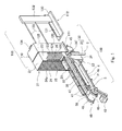
- Fig. 1 is a perspective view showing the exemplary configuration of a substrate conveying system 100.
- the substrate conveying system 100 is a system configured to convey substrates W.
- the substrate conveying system 100 is not particularly limited so long as it is configured to convey the substrates.
- the substrates there are cell substrates for a solar cell panel, semiconductor wafers such as silicon wafers, silicon carbide wafers, or sapphire wafers, and glass substrates for a thin display (liquid crystal display, organic EL display, etc.) treated in semiconductor process.
- the substrate conveying system 100 is a system for conveying the cell substrates for the solar cell in a manufacturing line of the solar cell panel.
- forward a downstream side in the direction in which the substrates are conveyed
- reverse an upstream side in the direction in which the substrates are conveyed
- the substrate conveying system 100 includes a substrate supply unit 2, a lift unit 3, a conveying unit 4, a controller 5 (control unit) (see Fig. 4 ) for controlling the operation of the substrate conveying system 100, and a frame member for allowing the components of the substrate conveying system 100 to be placed in a predetermined positional relationship.
- the predetermined position refers to a position which is appropriate for performing the conveying operation of the substrates W of the substrate conveying system 100.
- the substrate supply unit 2 includes a movable rack (storage case) 21 in which the substrates W are placed, and an up-down unit (down unit) 22 which moves up and down the movable rack 21.
- the movable rack 21 includes a pair of side walls 23 which face each other, and plural pairs of substrate support elements 24 provided on the side walls 23.
- the movable rack 21 is configured such that the rear wall and lower wall of a cartridge 110 as will be described later are omitted.
- the pair of side walls 23 of the movable rack 21, which face each other, are arranged in a direction perpendicular to a conveying direction, when viewed from a vertical direction, and an upper wall 27 connects the upper ends of the pair of side walls 23.
- a spacing between the pair of side walls 23 is set to a predetermined spacing which is required to place the substrates W on the substrate support elements 24 as will be described later.
- the front side and rear side of the movable rack 21 are entirely opened, to form a front opening 25 and a rear opening 26, respectively. This allows the substrates W to be carried into (stored into) and carried (taken) out of the movable rack 21 through the front opening 25 and the rear opening 26.
- the substrates W are carried into the movable rack 21 through the rear opening 26, and carried out of the movable rack 21 through the front opening 25.
- the lower side of the movable rack 21 is entirely opened to form a lower opening 28.
- the lift unit 3 and the conveying unit 4 are made closer to the lower surface of the substrate W through the lower opening 28.
- the lower opening 28 is provided, the present invention is not limited to this.
- the plural pairs of substrate support elements 24 support the both end portions of the plural substrates W such that the plural substrates W oriented horizontally are arranged to be vertically spaced from each other.
- the plural pairs of substrate support elements 24 are provided on the inner surfaces of the pair of side walls 23.
- the substrate support element 24 provided on one of the side walls 23 and the corresponding substrate support element 24 provided on the other side wall 23 form one of the pairs. These pairs are provided at predetermined pitches in the vertical direction.
- Each of the substrate support elements 24 has an inclined surface 24a extending obliquely downward toward the other side wall 23.
- the substrate support elements 24 support the both end portions of the plural substrates W such that the plural substrates W oriented horizontally are arranged to be vertically spaced from each other.
- the lower corner portions of the substrate W are in contact with the inclined surfaces 24a, and therefore, it becomes possible to prevent the obverse surface and reverse surface of the substrate W which are other than edges from contacting the substrate support element 24.
- the up-down unit 22 is mounted to the frame member. It is sufficient that the up-down unit 22 moves up and down the movable rack 21.
- the up-down unit 22 for example, there is a lift mechanism including a ball screw mechanism, a fluidic cylinder, or a wire (rope).
- the up-down unit 22 includes a case support section 31 supporting the movable rack 21, and a ball screw mechanism 32 coupled to the case support section 31 and configured to move up and down the case support section 31.
- the ball screw mechanism 32 includes a ball screw 33, and a slider 34 which is coupled to the case support section 31 and moved up and down according to the rotation of the ball screw 33.
- a transfer/loading section 105 is provided upstream of the movable rack 21 in the conveying direction.
- Fig. 2 is a perspective view showing the exemplary configuration of the transfer/loading section 105 of the substrate conveying system 100.
- the transfer/loading section 105 includes a placement table 111 on which the cartridge 110 storing the substrates is placed, and a transfer/loading unit 112 which transfers the substrates stored in the cartridge 110 to the movable rack 21, and loads the substrates into the movable rack 21.
- the movable rack 21 is configured such that the rear wall 121 and the lower wall of the cartridge 110 are omitted.
- the cartridge 110 includes a front opening 124 and substrate support elements 123 like the movable rack 21.
- the substrates W are carried into and out of the cartridge 110 through the front opening 124.
- the rear wall 121 of the cartridge 110 has a rear opening 125 which is opened so that the upstream end portions of all of the substrates W placed on the substrate support elements 126, in the conveying direction, are exposed.
- the placement table 111 is mounted to the frame member.
- the placement table 111 is positioned upstream of the substrate supply unit 2 in the conveying direction.
- the upper surface of the placement table 111 extends horizontally.
- the height of the placement table 111 is set so that the rear ends of the substrate support elements 24 of the movable rack 21 in the change position face the front ends of the substrate support elements 126 of the cartridge 110, respectively, in a state in which the cartridge 110 is placed on the placement table 111.
- the transfer/loading unit 112 is positioned upstream of the placement table 111 in the conveying direction.
- the transfer/loading unit 112 includes a base 130 which is mounted to the frame member and has a rail 131 extending in the conveying direction, a movable base 132 which is guided by the rail 131 to be movable to an upstream side or a downstream side in the conveying direction, push-in arms 133 extending horizontally from the movable base 132 to the downstream side in the conveying direction, a push-in plate 134 provided at the tip end of the push-in arms 133, and a drive section (not shown) which moves the movable base 132 to the upstream side or the downstream side in the conveying direction.
- the push-in plate 134 is inserted into the cartridge 110 through the rear opening 125 of the cartridge 110, and pushes the end portions of all of the substrates W stored in the cartridge 110 to the downstream side in the conveying direction. Since the front ends of the substrate support elements 126 of the cartridge 110 face the rear ends of the plural pairs of substrate support elements 24 of the movable rack 21, respectively, the pushed substrates slide on the substrate support elements 126 of the cartridge 110, and are placed on the inclined surfaces 24a of the movable rack 21.
- Fig. 3 is a view showing the exemplary structure for lifting-up the substrate of the substrate conveying system 100, when the substrate conveying system 100 is viewed from rear.
- the lift unit 3 has one or more ejection holes 35.
- the lift unit 3 includes a based body 36, and a drive section (e.g., pressurizing pump) which is not shown.
- the ejection holes 35 are formed in the base body 36.
- the base body 36 is a hollow box extending horizontally in the direction in which the substrates W are conveyed.
- the upstream end portion of the base body 36 is located within the lower opening 28 of the movable rack 21 when viewed from a vertical direction. Therefore, the base body 36 extends in the direction in which the substrates W are conveyed, through a space between the pair of side walls 23 of the movable rack 21, when viewed from a vertical direction.
- the base body 36 is mounted to the frame member.
- the base body 36 is configured such that its width, i.e., dimension in the direction which is perpendicular to the conveying direction, when viewed from the vertical direction, is set smaller than the dimension of the lower opening 28 of the movable rack 21, in the direction which is perpendicular to the conveying direction. This allows the lift unit 3 to be positioned between the pair of side walls 23 of the movable rack 21 (see Figs. 7 to 9 ).
- One or more ejection holes 35 are provided as points or to extend in the direction in which the substrates W are conveyed, from at least a region between the pair of side walls 23 of the movable rack 21, to a region which is other than the region between the side walls 23, when viewed from a vertical direction, and eject a gas upward.
- many ejection holes 35 are provided as points on the entire upper surface of the base body 36.
- the drive section of the lift unit 3 operates to supply air (gas) to the base body 36. Thereby, the air is ejected upward (including right above and obliquely upward) through the ejection holes 35.
- the substrate W1 of Fig. 3 which is supported on the substrate support elements 24 of the movable rack 21 can be lifted-up.
- lifted-up means that the obverse surface and reverse surface of the substrate W, which face the lift unit 3, do not contact the lift unit 3.
- the initial position of the movable rack 21 is defined as, for example, a position at which the substrate W supported on the substrate support elements 24 in a lowermost stage, of the substrate support elements 24 of the movable rack 21, is lifted-up by the pressure of the gas ejected through the ejection holes 35 (see Figs. 3 and 8 ).
- the end position of the movable rack 21 is defined as, for example, a position at which the substrate W supported on the substrate support elements 24 in an uppermost stage, of the substrate support elements 24 of the movable rack 21, is lifted-up by the pressure of the gas ejected through the ejection holes 35 (see Fig. 9 )
- the conveying unit 4 includes a conveyor (conveying member) 40, hook elements 41 extending upward from the conveyor 40, and a drive section 42 which moves the conveyor 40 in the conveying direction.
- the conveyor 40 extends through the space between the pair of side walls 23 of the movable rack 21 of the substrate supply unit 2 and along the ejection holes 35 of the lift unit 3, when viewed from the vertical direction.
- the upper surface of the conveyor 40 constitutes a conveying path of the substrate.
- the upstream end portion of the conveyor 40 in the conveying direction is positioned between the pair of side walls 23 of the movable rack 21, when viewed from the vertical direction.
- a handover position P is set in the downstream end portion of the conveyor 40 in the conveying direction.
- the handover position P is a position at which a transfer unit 150 (see Fig. 4 ) takes (carries) out the substrate W.
- the transfer unit 150 transfers the substrate W carried out from the handover position P to other position.
- the transfer unit there is a delta robot attached with a suction hand of a well-known Bernoulli type.
- the conveyor 40 has a pair of endless belts 46.
- the pair of endless belts 46 are wrapped around a pair of sprockets 45.
- the lift unit 3 is positioned in a region surrounded by the pair of endless belts 46 and the pair of sprockets 45, when viewed from the vertical direction.
- the drive section 42 rotates one of the sprockets 45 by a driving force, and as a result, the pair of endless belts 46 are rotated synchronously. In this way, the drive section 42 moves the conveyor 40 in the conveying direction.
- the hook elements 41 are provided on the conveyor 40 to extend upward such that they are arranged at intervals which are larger than the dimension of the substrate W in the conveying direction.
- the length of the hook elements 41 is set so that their tip ends are located higher than the substrate being lifted-up. This allows the hook elements 41 to push in the conveying direction the upstream end portions of the substrate in the conveying direction, in a state in which substrate is lifted-up by the pressure of the gas ejected through the ejection holes 35.
- plural pairs of the hook elements 41 are provided to extend upward on the obverse surfaces of the pair of endless belts 46.
- the hook element 41 provided on one of the endless belts 46 and the hook element 41 provided on the other endless belt 46 form a pair.
- the pair of hook elements 41 are arranged side by side in the direction perpendicular to the conveying direction, when viewed from the vertical direction. Therefore, when the drive section 42 causes the pair of endless belts 46 to be rotated by the driving force, the pair of hook elements are rotated synchronously in a state in which they are arranged in the direction perpendicular to the conveying direction.
- the hook elements 41 are provided to extend upward at pitches which are slightly larger than the dimension of the substrate W in the conveying direction.
- the hook elements 41 have a rectangular parallel-piped shape and protrude outward from the endless belts 46. Between the pair of hook elements 41 and adjacent hook elements 41, a substrate retaining region 47 for retaining the substrate W is formed.
- the conveyor 40 configured as described above, when the substrate W is positioned in the substrate retaining region 47 in a state in which the gas is ejected through the ejection holes 35, the substrate W is lifted-up by the pressure of the ejected gas. In this state, the position of the substrate W in the conveying direction is restricted by the pairs of hook elements 41 which are adjacent to the upstream and downstream end portions of the substrate W in the conveying direction.
- the pair of endless belts 46 are rotated, this substrate W is pushed to the downstream side in the conveying direction by the pairs of hook elements 41 at the upstream side in the conveying direction and conveyed to the handover position P.
- the substrate W since the substrate W is pushed by the pairs of hook elements 41 when it is conveyed, it is less likely to move sinuously.
- the substrate conveying system 100 further includes a pair of guides (restricting section) 50 extending in the conveying direction.
- the guides 50 are elongated- rectangular- plate-shaped members mounted to the frame member.
- the pair of guides 50 are provided at both sides of the conveyor 40, i.e., both sides of the lift unit 3 such that the guides 50 face each other.
- the pair of guides 50 are placed downstream of the substrate supply unit 2 in the conveying direction and adjacently to the substrate supply unit 2.
- the spacing between the pair of guides 50 is set slightly larger than the width of the substrate W in the direction perpendicular to the conveying direction.
- the pair of guides 50 to restrict the positions of the substrate W to be conveyed, the positions being in the direction from one of the both end portions to the other end portion of the substrate W (in the direction perpendicular to the conveying direction, when viewed from the vertical direction). Since the horizontal position of the substrate on the conveyor 40 is restricted by the hook elements 41 and the guides 50, the substrate is conveyed to the handover position P such that the substrate does not deviate from the substrate retaining region 47.
- Fig. 4 is a block diagram schematically showing the exemplary configuration of a control system of the substrate conveying system 100.
- the control system of the substrate conveying system 100 will be described with reference to Fig. 4 .
- the controller 5 of the substrate conveying system 100 includes a control section 55 including, for example, a processor such as CPU, and a storage section 56 including a memory such as ROM and RAM.
- the control section 55 may be constituted by a single control unit which performs centralized control or plural control units which cooperate with each other to perform distributed control.
- the control section 55 controls the operations of the drive sections of the up-down unit 22, the lift unit 3, the conveying unit 4, and the transfer/loading unit 112, thereby controlling the operations of these units.
- specified control programs are stored in the storage section 56.
- the control section 55 reads these control programs, and executes the control programs, to control the operation of the substrate conveying system 100.
- a substrate transfer completion signal output from the transfer unit 150 is input to the control section 55.
- arrows indicate the transmission direction of signals.
- the controller 5 controls the operations of the drive sections of the up-down unit 22, the lift unit 3, the conveying unit 4, and the transfer/loading unit 112.
- Fig. 5 is a flowchart showing the exemplary operation of the substrate conveying system 100.
- Fig. 6 is a flowchart showing the exemplary operation of the transfer/loading process of the substrate conveying system 100.
- Figs. 7 to 9 are flowcharts showing the exemplary operation of the substrate conveying system 100.
- control section 55 performs the transfer/loading process for transferring the substrates from the cartridge 110 and loading them into the movable rack 21 (step S21).
- the transfer/loading process is performed as follows.
- control section 55 positions the movable rack 21 in the change position of Fig. 7 (step S11).
- control section 55 pushes the push-in plate 134 of the transfer/loading unit 112 into the cartridge 110 through the rear opening 125 (step S 12). Thereby, all of the substrates W are transferred from the cartridge 110 and loaded into the movable rack 21.
- control section 55 moves the movable rack 21 down to the initial position of Fig. 8 (step S13). Thereby, the transfer/loading process is completed.
- the control section 55 drives the lift unit 3 to eject the air upward through the ejection holes 35 (step S2).
- This causes the substrate W supported on the substrate support elements 24 in a lowermost stage, of the substrate support elements 24 of the movable rack 21, to be lifted-up by the pressure of the gas ejected through the ejection holes 35.
- the hook elements 41 restrict the position of the substrate W in the conveying direction, and the pair of side walls 23 restrict the position of the substrate W in the direction perpendicular to the conveying direction. Therefore, the substrate W is retained in the substrate retaining region 47.
- the control section 55 rotates the conveyor 40 so that the substrate retaining region 47 which is adjacent to the upstream side of the substrate retaining region 47 in which the substrate W is retained, in the conveying direction, is positioned under the substrate W stored in the movable rack 21. More specifically, the pair of endless belts 46 are rotated by one pitch (step S3). Thereby, the substrate W located in the substrate retaining region 47, is conveyed to the downstream side in the conveying direction. At this time, the hook elements 41 restrict the position of the substrate W in the conveying direction, and the pair of guides 50 restrict the position of the substrate W in the direction perpendicular to the conveying direction. Therefore, the substrate W is retained in the substrate retaining region 47.
- control section 55 determines whether or not the movable rack 21 is in the end position of Fig. 9 .
- control section 55 determines that the movable rack 21 is not in the end position (NO in step S4), the control section 55 moves the movable rack 21 down by one pitch (step S5). This causes the substrate W which is adjacent to and above the above mentioned substrate W to be lifted-up by the pressure of the gas ejected through the ejection holes 35.
- control section 55 determines that the movable rack 21 is in the end position (YES in step S4), the control section 55 performs the transfer/loading process (step S6).
- control section 55 stands-by until it determines that the substrate is not in the handover position P, based on, for example, the substrate transfer completion signal received from the transfer unit 150 (step S7). In other words, the control section 55 stands-by until the substrate W is carried out, when the transfer unit 150 has not completed transferring the substrate W in the handover position.
- control section 55 determines that the substrate is not in the handover position P, the control section 55 performs the operation of step S3 again.
- the substrate conveying system 100 of the present invention is able to take each of the substrates W out of the movable rack 21, convey the substrate W and position the substrate W in the handover position P, without contacting the obverse surface and reverse surface of the substrate W which are other than edges. This makes it possible to prevent particles from adhering onto the obverse surface and reverse surface of the substrate W which are other than edges.
- the transfer/loading unit 112 transfers the substrates W stored in the cartridge 110 and loads them into the movable rack 21, the present invention is not limited to this.
- an operator may manually insert the substrates W into the movable rack 21.
- the movable rack 21 in which the substrates W are stored may be exchanged with the movable rack 21 from which the substrates W have been carried out.
- the pair of guides 50 are provided at both sides of the conveying unit 4, the present invention is not limited to this.
- the guide 50 may be provided at one side of the conveying unit 4.
- the lift unit 3 may be inclined toward the guide 50. In this configuration, the substrate W being lifted-up by the pressure of the air ejected through the ejection holes 35 of the lift unit 3, is moved toward the side at which guide 50 is located, and the position of the substrate W in the direction perpendicular to the conveying direction, is restricted by the guide 50.
- the gas ejected through the ejection holes 35 is not limited to the air, and a desired gas may be used.
- a substrate conveying system of the present invention is effectively applicable to a manufacturing line of cell substrates for a solar cell panel, semiconductor used to fabricate fine circuits on substrates, display panels, etc..
Landscapes
- Engineering & Computer Science (AREA)
- Mechanical Engineering (AREA)
- Physics & Mathematics (AREA)
- Fluid Mechanics (AREA)
- Container, Conveyance, Adherence, Positioning, Of Wafer (AREA)
- Pusher Or Impeller Conveyors (AREA)
- Warehouses Or Storage Devices (AREA)
Abstract
Description
- The present invention relates to a substrate conveying system which conveys substrates. Particularly, the present invention relates to a substrate conveying system which takes the substrates out of a storage case, and conveys the substrates.
- Conventionally, there is known a substrate conveying device which takes (carries) substrates such as glass substrates out of a cassette (see e.g. Patent Literature 1).
- This substrate conveying device includes conveying rollers arranged in two rows, and a hand unit. The conveying rollers in the rows are arranged such that they are apart from each other in a direction in which the substrates are conveyed. The hand unit extends in a direction perpendicular to the direction in which the substrates are conveyed, and is positioned to be slightly lower than the conveying rollers. The hand unit has on its upper surface plural ejection holes through which compressed air supplied from a blower or the like is ejected. When the substrates are taken out of the substrate cassette, the both end portions of the lower surface of each of the substrates are directly supported by the conveying rollers, a portion of the substrate which portion is closer to the center than portions thereof which contact the conveying rollers is supported in a non-contact state by the compressed air ejected through the ejections holes, and the conveying rollers are rotated. In this configuration, each of the substrates is taken out of the substrate cassette due to a friction force generated by the contact with the conveying rollers.
- Patent Literature 1: Japanese Laid-Open Patent Application Publication NO.
2008-98198 - To prevent particles from adhering onto processed surfaces (upper surface and lower surface) of each of the substrates, it is sometimes necessary to reduce the degree of a contact between the processed surfaces of the substrate and the substrate conveying device to a smallest degree, when the substrate is taken out of the substrate cassette.
- However, since the conventional substrate conveying device is configured such that the both end portions of the lower surface of each of the substrates contact the conveying rollers, the particles tend to adhere onto the processed surfaces of the substrate.
- To solve the above described problem associated with the prior art, there is provided a substrate conveying system comprising: a substrate supply unit including a storage case including a pair of side walls facing each other, and plural pairs of support elements provided on the side walls to support both end portions of plural substrates such that the plural substrates oriented horizontally are arranged to be vertically spaced apart from each other, and a down unit which moves the storage case down; a lift unit having one or more ejection holes which are provided as points or to extend in a conveying direction of the substrates, from at least a region between the pair of side walls of the storage case to a region which is other than the region between the pair of side walls, when viewed from a vertical direction, and eject a gas upward, the lift unit being configured to lift-up the substrate supported on the support elements by a pressure of the gas ejected through the one or more ejection holes, when the down unit moves the storage case down; and a conveying unit including a conveying member extending through the region between the pair of side walls of the storage case of the substrate supply unit and along the one or more ejection holes of the lift unit which are provided as points or to extend in the conveying direction, when viewed from the vertical direction, plural hook elements provided on the conveying member to extend upward such that the hook elements are arranged at intervals which are larger than a dimension of the substrate in the conveying direction, and a drive section for moving the conveying member in the conveying direction, the hook elements being configured to push in the conveying direction upstream end portions of the substrate in the conveying direction, in a state in which the substrate is lifted-up by the pressure of the gas ejected through the ejection holes.
- In accordance with this configuration, the substrate conveying system is able to take each of the substrates out of the storage case and convey the substrate, without contacting the obverse surface and reverse surface of the substrate which are other than edges. This makes it possible to prevent particles from adhering onto the obverse surface and reverse surface of the substrate which are other than edges.
- The substrate conveying system of the above invention, may comprise: a restricting section extending in the conveying direction and configured to restrict a position of the both end portions of the substrate being conveyed by the conveying unit.
- In accordance with this configuration, it becomes possible to prevent the substrate from deviating from the conveying path of the conveying unit by restricting its position.
- In the above substrate conveying system, the restricting section may have a pair of restricting sections at both sides of the one or more ejection holes which are provided as points or to extend in the conveying direction such that the restricting sections face each other.
- In accordance with this configuration, it becomes possible to prevent the substrate from deviating from a position above the lift unit by restricting the position.
- In the above substrate conveying system, the conveying unit may include a pair of endless belts as the conveying member; and the pair of endless belts are driven by the drive section to be rotated such that the hook elements are rotated synchronously with rotation of the endless belts in a state in which the hook elements are arranged in a direction perpendicular to the conveying direction, when viewed from the vertical direction.
- In accordance with this configuration, it becomes possible to prevent the substrate pushed by the hook elements from moving sinuously.
- The present invention has been configured as described above, and has advantages that it becomes possible to prevent particles from adhering onto the obverse surface and reverse surface of the substrate which are other than edges.
-
-
Fig. 1 is a perspective view showing the exemplary configuration of a substrate conveying system according to an embodiment of the present invention. -
Fig. 2 is a perspective view showing the exemplary configuration of a transfer/loading section of the substrate conveying system ofFig. 1 . -
Fig. 3 is a view showing the exemplary structure for lifting-up substrates of the substrate conveying system ofFig. 1 , when the substrate conveying system is viewed from rear. -
Fig. 4 is a block diagram schematically showing the exemplary configuration of a control system of the substrate conveying system ofFig. 1 . -
Fig. 5 is a flowchart showing the exemplary operation of the substrate conveying system ofFig. 1 . -
Fig. 6 is a flowchart showing the exemplary operation of the substrate conveying system ofFig. 1 . -
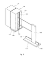
Fig. 7 is a view showing the exemplary operation of the substrate conveying system ofFig. 1 . -
Fig. 8 is a view showing the exemplary operation of the substrate conveying system ofFig. 1 . -
Fig. 9 is a view showing the exemplary operation of the substrate conveying system ofFig. 1 . - Hereinafter, the embodiment of the present invention will be described with reference to the drawings. Hereinafter, throughout the drawings, the same or corresponding components are identified by the same reference numerals, and will not be described.
-
Fig. 1 is a perspective view showing the exemplary configuration of asubstrate conveying system 100. - The
substrate conveying system 100 is a system configured to convey substrates W. Thesubstrate conveying system 100 is not particularly limited so long as it is configured to convey the substrates. As examples of the substrates, there are cell substrates for a solar cell panel, semiconductor wafers such as silicon wafers, silicon carbide wafers, or sapphire wafers, and glass substrates for a thin display (liquid crystal display, organic EL display, etc.) treated in semiconductor process. In the present embodiment, thesubstrate conveying system 100 is a system for conveying the cell substrates for the solar cell in a manufacturing line of the solar cell panel. - Hereinafter, in some cases, for easier explanation, a downstream side in the direction in which the substrates are conveyed will be referred to as "forward", and an upstream side in the direction in which the substrates are conveyed will be referred to as "rearward".
- As shown in
Fig. 1 , thesubstrate conveying system 100 includes asubstrate supply unit 2, alift unit 3, aconveying unit 4, a controller 5 (control unit) (seeFig. 4 ) for controlling the operation of thesubstrate conveying system 100, and a frame member for allowing the components of thesubstrate conveying system 100 to be placed in a predetermined positional relationship. As used herein, the predetermined position refers to a position which is appropriate for performing the conveying operation of the substrates W of thesubstrate conveying system 100. - The
substrate supply unit 2 includes a movable rack (storage case) 21 in which the substrates W are placed, and an up-down unit (down unit) 22 which moves up and down themovable rack 21. - The
movable rack 21 includes a pair ofside walls 23 which face each other, and plural pairs ofsubstrate support elements 24 provided on theside walls 23. - In the present embodiment, the
movable rack 21 is configured such that the rear wall and lower wall of acartridge 110 as will be described later are omitted. - As shown in
Fig. 1 , the pair ofside walls 23 of themovable rack 21, which face each other, are arranged in a direction perpendicular to a conveying direction, when viewed from a vertical direction, and anupper wall 27 connects the upper ends of the pair ofside walls 23. In this way, a spacing between the pair ofside walls 23 is set to a predetermined spacing which is required to place the substrates W on thesubstrate support elements 24 as will be described later. - The front side and rear side of the
movable rack 21 are entirely opened, to form a front opening 25 and arear opening 26, respectively. This allows the substrates W to be carried into (stored into) and carried (taken) out of themovable rack 21 through the front opening 25 and therear opening 26. In the present embodiment, as will be described later, the substrates W are carried into themovable rack 21 through therear opening 26, and carried out of themovable rack 21 through the front opening 25. The lower side of themovable rack 21 is entirely opened to form alower opening 28. As will be described later, thelift unit 3 and the conveyingunit 4 are made closer to the lower surface of the substrate W through thelower opening 28. Although in the present embodiment, thelower opening 28 is provided, the present invention is not limited to this. - The plural pairs of
substrate support elements 24 support the both end portions of the plural substrates W such that the plural substrates W oriented horizontally are arranged to be vertically spaced from each other. In the present embodiment, as shown inFigs. 1 and2 , the plural pairs ofsubstrate support elements 24 are provided on the inner surfaces of the pair ofside walls 23. Thesubstrate support element 24 provided on one of theside walls 23 and the correspondingsubstrate support element 24 provided on theother side wall 23 form one of the pairs. These pairs are provided at predetermined pitches in the vertical direction. Each of thesubstrate support elements 24 has aninclined surface 24a extending obliquely downward toward theother side wall 23. In a state in which the substrates W are placed on theinclined surfaces 24a of the plural pairs ofsubstrate support elements 24 such that the substrate W bridges a space between theinclined surfaces 24a, thesubstrate support elements 24 support the both end portions of the plural substrates W such that the plural substrates W oriented horizontally are arranged to be vertically spaced from each other. In this state, the lower corner portions of the substrate W are in contact with theinclined surfaces 24a, and therefore, it becomes possible to prevent the obverse surface and reverse surface of the substrate W which are other than edges from contacting thesubstrate support element 24. - The up-down
unit 22 is mounted to the frame member. It is sufficient that the up-downunit 22 moves up and down themovable rack 21. As an example of the up-downunit 22, for example, there is a lift mechanism including a ball screw mechanism, a fluidic cylinder, or a wire (rope). In the present embodiment, the up-downunit 22 includes acase support section 31 supporting themovable rack 21, and aball screw mechanism 32 coupled to thecase support section 31 and configured to move up and down thecase support section 31. Theball screw mechanism 32 includes aball screw 33, and aslider 34 which is coupled to thecase support section 31 and moved up and down according to the rotation of theball screw 33. When a drive section (not shown) rotates theball screw 33, thecase support section 31 is moved up or down, to move themovable rack 21 between a change position (seeFig. 7 ) of the cartridge and an end position (seeFig. 9 ) which is below the change position. In addition, an initial position (seeFig. 8 ) is set between the change position and the end position. The change position, the end position, and the initial position will be described in detail later. - In the present embodiment, a transfer/
loading section 105 is provided upstream of themovable rack 21 in the conveying direction. -
Fig. 2 is a perspective view showing the exemplary configuration of the transfer/loading section 105 of thesubstrate conveying system 100. - As shown in
Figs. 1 and2 , the transfer/loading section 105 includes a placement table 111 on which thecartridge 110 storing the substrates is placed, and a transfer/loading unit 112 which transfers the substrates stored in thecartridge 110 to themovable rack 21, and loads the substrates into themovable rack 21. - As described above, the
movable rack 21 is configured such that therear wall 121 and the lower wall of thecartridge 110 are omitted. In other words, thecartridge 110 includes afront opening 124 andsubstrate support elements 123 like themovable rack 21. The substrates W are carried into and out of thecartridge 110 through thefront opening 124. Therear wall 121 of thecartridge 110 has arear opening 125 which is opened so that the upstream end portions of all of the substrates W placed on thesubstrate support elements 126, in the conveying direction, are exposed. - The placement table 111 is mounted to the frame member. The placement table 111 is positioned upstream of the
substrate supply unit 2 in the conveying direction. The upper surface of the placement table 111 extends horizontally. The height of the placement table 111 is set so that the rear ends of thesubstrate support elements 24 of themovable rack 21 in the change position face the front ends of thesubstrate support elements 126 of thecartridge 110, respectively, in a state in which thecartridge 110 is placed on the placement table 111. - The transfer/
loading unit 112 is positioned upstream of the placement table 111 in the conveying direction. The transfer/loading unit 112 includes a base 130 which is mounted to the frame member and has arail 131 extending in the conveying direction, amovable base 132 which is guided by therail 131 to be movable to an upstream side or a downstream side in the conveying direction, push-inarms 133 extending horizontally from themovable base 132 to the downstream side in the conveying direction, a push-inplate 134 provided at the tip end of the push-inarms 133, and a drive section (not shown) which moves themovable base 132 to the upstream side or the downstream side in the conveying direction. - In the transfer/
loading unit 112, when themovable base 132 moves to the downstream side in the conveying direction, the push-inplate 134 is inserted into thecartridge 110 through therear opening 125 of thecartridge 110, and pushes the end portions of all of the substrates W stored in thecartridge 110 to the downstream side in the conveying direction. Since the front ends of thesubstrate support elements 126 of thecartridge 110 face the rear ends of the plural pairs ofsubstrate support elements 24 of themovable rack 21, respectively, the pushed substrates slide on thesubstrate support elements 126 of thecartridge 110, and are placed on theinclined surfaces 24a of themovable rack 21. -
Fig. 3 is a view showing the exemplary structure for lifting-up the substrate of thesubstrate conveying system 100, when thesubstrate conveying system 100 is viewed from rear. - As shown in
Figs. 1 and3 , thelift unit 3 has one or more ejection holes 35. - In the present embodiment, the
lift unit 3 includes a basedbody 36, and a drive section (e.g., pressurizing pump) which is not shown. The ejection holes 35 are formed in thebase body 36. - The
base body 36 is a hollow box extending horizontally in the direction in which the substrates W are conveyed. The upstream end portion of thebase body 36 is located within thelower opening 28 of themovable rack 21 when viewed from a vertical direction. Therefore, thebase body 36 extends in the direction in which the substrates W are conveyed, through a space between the pair ofside walls 23 of themovable rack 21, when viewed from a vertical direction. Thebase body 36 is mounted to the frame member. - As shown in
Figs. 1 and3 , thebase body 36 is configured such that its width, i.e., dimension in the direction which is perpendicular to the conveying direction, when viewed from the vertical direction, is set smaller than the dimension of thelower opening 28 of themovable rack 21, in the direction which is perpendicular to the conveying direction. This allows thelift unit 3 to be positioned between the pair ofside walls 23 of the movable rack 21 (seeFigs. 7 to 9 ). - One or more ejection holes 35 are provided as points or to extend in the direction in which the substrates W are conveyed, from at least a region between the pair of
side walls 23 of themovable rack 21, to a region which is other than the region between theside walls 23, when viewed from a vertical direction, and eject a gas upward. In the present embodiment, many ejection holes 35 are provided as points on the entire upper surface of thebase body 36. - The drive section of the
lift unit 3 operates to supply air (gas) to thebase body 36. Thereby, the air is ejected upward (including right above and obliquely upward) through the ejection holes 35. By the pressure of the gas ejected through the ejection holes 35, the substrate W1 ofFig. 3 which is supported on thesubstrate support elements 24 of themovable rack 21 can be lifted-up. The term "lifted-up" means that the obverse surface and reverse surface of the substrate W, which face thelift unit 3, do not contact thelift unit 3. - The initial position of the
movable rack 21 is defined as, for example, a position at which the substrate W supported on thesubstrate support elements 24 in a lowermost stage, of thesubstrate support elements 24 of themovable rack 21, is lifted-up by the pressure of the gas ejected through the ejection holes 35 (seeFigs. 3 and8 ). The end position of themovable rack 21 is defined as, for example, a position at which the substrate W supported on thesubstrate support elements 24 in an uppermost stage, of thesubstrate support elements 24 of themovable rack 21, is lifted-up by the pressure of the gas ejected through the ejection holes 35 (seeFig. 9 ) - The conveying
unit 4 includes a conveyor (conveying member) 40,hook elements 41 extending upward from theconveyor 40, and adrive section 42 which moves theconveyor 40 in the conveying direction. - The
conveyor 40 extends through the space between the pair ofside walls 23 of themovable rack 21 of thesubstrate supply unit 2 and along the ejection holes 35 of thelift unit 3, when viewed from the vertical direction. The upper surface of theconveyor 40 constitutes a conveying path of the substrate. In the present embodiment, the upstream end portion of theconveyor 40 in the conveying direction, is positioned between the pair ofside walls 23 of themovable rack 21, when viewed from the vertical direction. A handover position P is set in the downstream end portion of theconveyor 40 in the conveying direction. The handover position P is a position at which a transfer unit 150 (seeFig. 4 ) takes (carries) out the substrate W. Thetransfer unit 150 transfers the substrate W carried out from the handover position P to other position. As an example of the transfer unit, there is a delta robot attached with a suction hand of a well-known Bernoulli type. - The
conveyor 40 has a pair ofendless belts 46. The pair ofendless belts 46 are wrapped around a pair ofsprockets 45. Thelift unit 3 is positioned in a region surrounded by the pair ofendless belts 46 and the pair ofsprockets 45, when viewed from the vertical direction. Thedrive section 42 rotates one of thesprockets 45 by a driving force, and as a result, the pair ofendless belts 46 are rotated synchronously. In this way, thedrive section 42 moves theconveyor 40 in the conveying direction. - The
hook elements 41 are provided on theconveyor 40 to extend upward such that they are arranged at intervals which are larger than the dimension of the substrate W in the conveying direction. The length of thehook elements 41 is set so that their tip ends are located higher than the substrate being lifted-up. This allows thehook elements 41 to push in the conveying direction the upstream end portions of the substrate in the conveying direction, in a state in which substrate is lifted-up by the pressure of the gas ejected through the ejection holes 35. In the present embodiment, plural pairs of thehook elements 41 are provided to extend upward on the obverse surfaces of the pair ofendless belts 46. Thehook element 41 provided on one of theendless belts 46 and thehook element 41 provided on the otherendless belt 46 form a pair. The pair ofhook elements 41 are arranged side by side in the direction perpendicular to the conveying direction, when viewed from the vertical direction. Therefore, when thedrive section 42 causes the pair ofendless belts 46 to be rotated by the driving force, the pair of hook elements are rotated synchronously in a state in which they are arranged in the direction perpendicular to the conveying direction. Thehook elements 41 are provided to extend upward at pitches which are slightly larger than the dimension of the substrate W in the conveying direction. Thehook elements 41 have a rectangular parallel-piped shape and protrude outward from theendless belts 46. Between the pair ofhook elements 41 andadjacent hook elements 41, asubstrate retaining region 47 for retaining the substrate W is formed. - In accordance with the
conveyor 40 configured as described above, when the substrate W is positioned in thesubstrate retaining region 47 in a state in which the gas is ejected through the ejection holes 35, the substrate W is lifted-up by the pressure of the ejected gas. In this state, the position of the substrate W in the conveying direction is restricted by the pairs ofhook elements 41 which are adjacent to the upstream and downstream end portions of the substrate W in the conveying direction. When the pair ofendless belts 46 are rotated, this substrate W is pushed to the downstream side in the conveying direction by the pairs ofhook elements 41 at the upstream side in the conveying direction and conveyed to the handover position P. As described above, since the substrate W is pushed by the pairs ofhook elements 41 when it is conveyed, it is less likely to move sinuously. - In the present embodiment, the
substrate conveying system 100 further includes a pair of guides (restricting section) 50 extending in the conveying direction. Theguides 50 are elongated- rectangular- plate-shaped members mounted to the frame member. The pair ofguides 50 are provided at both sides of theconveyor 40, i.e., both sides of thelift unit 3 such that theguides 50 face each other. The pair ofguides 50 are placed downstream of thesubstrate supply unit 2 in the conveying direction and adjacently to thesubstrate supply unit 2. The spacing between the pair ofguides 50 is set slightly larger than the width of the substrate W in the direction perpendicular to the conveying direction. This allows the pair ofguides 50 to restrict the positions of the substrate W to be conveyed, the positions being in the direction from one of the both end portions to the other end portion of the substrate W (in the direction perpendicular to the conveying direction, when viewed from the vertical direction). Since the horizontal position of the substrate on theconveyor 40 is restricted by thehook elements 41 and theguides 50, the substrate is conveyed to the handover position P such that the substrate does not deviate from thesubstrate retaining region 47. -
Fig. 4 is a block diagram schematically showing the exemplary configuration of a control system of thesubstrate conveying system 100. Hereinafter, the control system of thesubstrate conveying system 100 will be described with reference toFig. 4 . - The
controller 5 of thesubstrate conveying system 100 includes acontrol section 55 including, for example, a processor such as CPU, and astorage section 56 including a memory such as ROM and RAM. Thecontrol section 55 may be constituted by a single control unit which performs centralized control or plural control units which cooperate with each other to perform distributed control. Thecontrol section 55 controls the operations of the drive sections of the up-downunit 22, thelift unit 3, the conveyingunit 4, and the transfer/loading unit 112, thereby controlling the operations of these units. For example, specified control programs are stored in thestorage section 56. Thecontrol section 55 reads these control programs, and executes the control programs, to control the operation of thesubstrate conveying system 100. A substrate transfer completion signal output from thetransfer unit 150 is input to thecontrol section 55. InFigs. 4 , arrows indicate the transmission direction of signals. - Next, the exemplary operation of the
substrate conveying system 100 will be described, The operation is carried out by thecontroller 5's operation for controlling the operations of the drive sections of the up-downunit 22, thelift unit 3, the conveyingunit 4, and the transfer/loading unit 112. -
Fig. 5 is a flowchart showing the exemplary operation of thesubstrate conveying system 100.Fig. 6 is a flowchart showing the exemplary operation of the transfer/loading process of thesubstrate conveying system 100.Figs. 7 to 9 are flowcharts showing the exemplary operation of thesubstrate conveying system 100. - Initially, the
control section 55 performs the transfer/loading process for transferring the substrates from thecartridge 110 and loading them into the movable rack 21 (step S21). The transfer/loading process is performed as follows. - Firstly, the
control section 55 positions themovable rack 21 in the change position ofFig. 7 (step S11). - Then, the
control section 55 pushes the push-inplate 134 of the transfer/loading unit 112 into thecartridge 110 through the rear opening 125 (step S 12). Thereby, all of the substrates W are transferred from thecartridge 110 and loaded into themovable rack 21. - Then, the
control section 55 moves themovable rack 21 down to the initial position ofFig. 8 (step S13). Thereby, the transfer/loading process is completed. - Then, the
control section 55 drives thelift unit 3 to eject the air upward through the ejection holes 35 (step S2). This causes the substrate W supported on thesubstrate support elements 24 in a lowermost stage, of thesubstrate support elements 24 of themovable rack 21, to be lifted-up by the pressure of the gas ejected through the ejection holes 35. At this time, thehook elements 41 restrict the position of the substrate W in the conveying direction, and the pair ofside walls 23 restrict the position of the substrate W in the direction perpendicular to the conveying direction. Therefore, the substrate W is retained in thesubstrate retaining region 47. - Then, the
control section 55 rotates theconveyor 40 so that thesubstrate retaining region 47 which is adjacent to the upstream side of thesubstrate retaining region 47 in which the substrate W is retained, in the conveying direction, is positioned under the substrate W stored in themovable rack 21. More specifically, the pair ofendless belts 46 are rotated by one pitch (step S3). Thereby, the substrate W located in thesubstrate retaining region 47, is conveyed to the downstream side in the conveying direction. At this time, thehook elements 41 restrict the position of the substrate W in the conveying direction, and the pair ofguides 50 restrict the position of the substrate W in the direction perpendicular to the conveying direction. Therefore, the substrate W is retained in thesubstrate retaining region 47. - Then, the
control section 55 determines whether or not themovable rack 21 is in the end position ofFig. 9 . - When the
control section 55 determines that themovable rack 21 is not in the end position (NO in step S4), thecontrol section 55 moves themovable rack 21 down by one pitch (step S5). This causes the substrate W which is adjacent to and above the above mentioned substrate W to be lifted-up by the pressure of the gas ejected through the ejection holes 35. - On the other hand, when the
control section 55 determines that themovable rack 21 is in the end position (YES in step S4), thecontrol section 55 performs the transfer/loading process (step S6). - Then, the
control section 55 stands-by until it determines that the substrate is not in the handover position P, based on, for example, the substrate transfer completion signal received from the transfer unit 150 (step S7). In other words, thecontrol section 55 stands-by until the substrate W is carried out, when thetransfer unit 150 has not completed transferring the substrate W in the handover position. - When the
control section 55 determines that the substrate is not in the handover position P, thecontrol section 55 performs the operation of step S3 again. - As described above, the
substrate conveying system 100 of the present invention is able to take each of the substrates W out of themovable rack 21, convey the substrate W and position the substrate W in the handover position P, without contacting the obverse surface and reverse surface of the substrate W which are other than edges. This makes it possible to prevent particles from adhering onto the obverse surface and reverse surface of the substrate W which are other than edges. - Although in the above described embodiment, the transfer/
loading unit 112 transfers the substrates W stored in thecartridge 110 and loads them into themovable rack 21, the present invention is not limited to this. Alternatively, an operator may manually insert the substrates W into themovable rack 21. Or, themovable rack 21 in which the substrates W are stored may be exchanged with themovable rack 21 from which the substrates W have been carried out. - Although in the above described embodiment, the pair of
guides 50 are provided at both sides of the conveyingunit 4, the present invention is not limited to this. Alternatively, for example, theguide 50 may be provided at one side of the conveyingunit 4. In this case, thelift unit 3 may be inclined toward theguide 50. In this configuration, the substrate W being lifted-up by the pressure of the air ejected through the ejection holes 35 of thelift unit 3, is moved toward the side at which guide 50 is located, and the position of the substrate W in the direction perpendicular to the conveying direction, is restricted by theguide 50. - Moreover, the gas ejected through the ejection holes 35 is not limited to the air, and a desired gas may be used.
- Numeral modifications and alternative embodiments of the present invention will be apparent to those skilled in the art in view of the foregoing description. Accordingly, the description is to be construed as illustrative only, and is provided for the purpose of teaching those skilled in the art the best mode of carrying out the invention. The details of the structure and/or function may be varied substantially without departing from the spirit of the invention.
- A substrate conveying system of the present invention is effectively applicable to a manufacturing line of cell substrates for a solar cell panel, semiconductor used to fabricate fine circuits on substrates, display panels, etc..
-
- 2
- substrate supply unit
- 3
- lift unit
- 4
- conveying unit
- 5
- controller
- 21
- movable rack
- 22
- up-down unit
- 23
- side wall
- 24
- substrate support element
- 24a
- inclined surface
- 25
- front opening
- 26
- rear opening
- 27
- upper wall
- 28
- lower opening
- 31
- case support section
- 32
- ball screw mechanism
- 33
- ball screw
- 34
- slider
- 35
- ejection holes
- 36
- base body
- 40
- conveyor
- 41
- hook element
- 42
- drive section
- 45
- sprocket
- 46
- endless belt
- 47
- substrate retaining region
- 50
- guide
- 55
- control section
- 56
- storage section
- 100
- substrate conveying system
- 105
- transfer/loading section
- 110
- cartridge
- 111
- placement table
- 112
- transfer/loading unit
- 121
- rear wall
- 123
- substrate support element
- 124
- front opening
- 125
- rear opening
- 126
- substrate support element
- 130
- base
- 131
- rail
- 132
- movable base
- 133
- push-in arm
- 134
- push-in plate
- 150
- transfer unit
Claims (4)
- A substrate conveying system comprising:a substrate supply unit including a storage case including a pair of side walls facing each other, and plural pairs of support elements provided on the side walls to support both end portions of plural substrates such that the plural substrates oriented horizontally are arranged to be vertically spaced apart from each other, and a down unit which moves the storage case down;a lift unit having one or more ejection holes which are provided as points or to extend in a conveying direction of the substrates, from at least a region between the pair of side walls of the storage case to a region which is other than the region between the pair of side walls, when viewed from a vertical direction, and eject a gas upward, the lift unit being configured to lift-up the substrate supported on the support elements by a pressure of the gas ejected through the one or more ejection holes, when the down unit moves the storage case down; anda conveying unit including a conveying member extending through the region between the pair of side walls of the storage case of the substrate supply unit and along the one or more ejection holes of the lift unit which are provided as points or to extend in the conveying direction, when viewed from the vertical direction, plural hook elements provided on the conveying member to extend upward such that the hook elements are arranged at intervals which are larger than a dimension of the substrate in the conveying direction, and a drive section for moving the conveying member in the conveying direction, the hook elements being configured to push in the conveying direction upstream end portions of the substrate in the conveying direction, in a state in which the substrate is lifted-up by the pressure of the gas ejected through the ejection holes.
- The substrate conveying system according to claim 1, comprising:a restricting section extending in the conveying direction and configured to restrict positions of the substrate being conveyed by the conveying unit, the positions being in a direction from one of the both end portions of the substrate to the other end portion.
- The substrate conveying system according to claim 2,
wherein the restricting section has a pair of restricting sections at both sides of the one or more ejection holes which are provided as points or to extend in the conveying direction of the conveying unit such that the restricting sections face each other. - The substrate conveying system according to any one of claims 1 to 3,
wherein the conveying unit includes a pair of endless belts as the conveying member; and
the pair of endless belts are driven by the drive section to be rotated such that the hook elements are rotated synchronously with rotation of the endless belts in a state in which the hook elements are arranged in a direction perpendicular to the conveying direction, when viewed from the vertical direction.
Applications Claiming Priority (2)
| Application Number | Priority Date | Filing Date | Title |
|---|---|---|---|
| JP2012139883A JP6039260B2 (en) | 2012-06-21 | 2012-06-21 | Substrate transfer system |
| PCT/JP2013/003636 WO2013190800A1 (en) | 2012-06-21 | 2013-06-10 | Substrate transport system |
Publications (3)
| Publication Number | Publication Date |
|---|---|
| EP2866252A1 true EP2866252A1 (en) | 2015-04-29 |
| EP2866252A4 EP2866252A4 (en) | 2016-02-17 |
| EP2866252B1 EP2866252B1 (en) | 2019-10-02 |
Family
ID=49768415
Family Applications (1)
| Application Number | Title | Priority Date | Filing Date |
|---|---|---|---|
| EP13806319.3A Active EP2866252B1 (en) | 2012-06-21 | 2013-06-10 | Substrate conveying system |
Country Status (6)
| Country | Link |
|---|---|
| US (1) | US9773691B2 (en) |
| EP (1) | EP2866252B1 (en) |
| JP (1) | JP6039260B2 (en) |
| KR (1) | KR101707090B1 (en) |
| CN (1) | CN104364891B (en) |
| WO (1) | WO2013190800A1 (en) |
Cited By (3)
| Publication number | Priority date | Publication date | Assignee | Title |
|---|---|---|---|---|
| EP3660888A1 (en) * | 2018-11-29 | 2020-06-03 | JOT Automation Oy | Conveyor arrangement and method for conveying electronic device |
| CN111268408A (en) * | 2019-12-26 | 2020-06-12 | 彭茶妹 | Automatic board receiving frame for PCB |
| EP3680197A1 (en) * | 2019-01-10 | 2020-07-15 | Toyota Boshoku Kabushiki Kaisha | Workpiece transfer apparatus |
Families Citing this family (23)
| Publication number | Priority date | Publication date | Assignee | Title |
|---|---|---|---|---|
| KR101606705B1 (en) * | 2014-09-02 | 2016-03-28 | 비아이 이엠티 주식회사 | Substrate Transfer Apparatus |
| CN105883419A (en) * | 2014-10-10 | 2016-08-24 | 杨德宁 | Air flotation device automatic-conveying line and method capable of achieving segmented control |
| US10804422B2 (en) * | 2015-12-01 | 2020-10-13 | Sunpower Corporation | Multi-operation tool for photovoltaic cell processing |
| US10242897B2 (en) | 2015-12-14 | 2019-03-26 | Solarcity Corporation | Micro-environment container for photovoltaic cells |
| US10449641B2 (en) * | 2016-02-18 | 2019-10-22 | Panasonic Intellectual Property Management Co., Ltd. | System for manufacturing assembly board and method for installing undersupporting device of the system |
| KR101727125B1 (en) * | 2016-03-02 | 2017-04-14 | (주)지테크 | Substrate Transfer Apparatus |
| US10074554B2 (en) * | 2016-06-27 | 2018-09-11 | Tel Nexx, Inc. | Workpiece loader for a wet processing system |
| CN108074847A (en) * | 2016-11-10 | 2018-05-25 | 英属开曼群岛商精曜有限公司 | A kind of wafer conveyance device |
| JP2018083700A (en) * | 2016-11-25 | 2018-05-31 | 日本電産サンキョー株式会社 | Method of controlling substrate supply device and method of controlling substrate supply/recovery device |
| KR102350865B1 (en) * | 2017-02-23 | 2022-01-13 | 주식회사 원익아이피에스 | Substrate processing system, and substrate exchanging module |
| JP2019067948A (en) * | 2017-10-02 | 2019-04-25 | 川崎重工業株式会社 | Substrate transfer device |
| CN109920748A (en) * | 2017-12-12 | 2019-06-21 | 湘潭宏大真空技术股份有限公司 | Large-area glass substrate loader |
| CN108100579A (en) * | 2017-12-15 | 2018-06-01 | 董桂芳 | A kind of LED bonders feed mechanism and feeding method |
| CN108861353B (en) * | 2018-07-15 | 2019-11-22 | 徐州诚凯知识产权服务有限公司 | A building solar roof panel conveyor |
| CN109335684B (en) * | 2018-09-28 | 2020-07-31 | 芜湖华宇彩晶科技有限公司 | Screen conveying device of ultrasonic cleaning machine |
| CN111439590A (en) * | 2019-01-16 | 2020-07-24 | 上海襄万机电科技有限公司 | A material suspension circulating conveying device |
| DE102019122839A1 (en) * | 2019-08-26 | 2021-03-04 | Miva Technologies Gmbh | Method and exposure device for exposing a light-sensitive recording medium |
| CN110562664A (en) * | 2019-09-10 | 2019-12-13 | 深圳市凯中精密技术股份有限公司 | A lifting mechanism and its feeding device |
| USD956834S1 (en) * | 2021-01-19 | 2022-07-05 | Edward O'Hanrahan, Jr. | Forged roller assembly |
| USD957483S1 (en) * | 2021-01-19 | 2022-07-12 | Edward O'Hanrahan, Jr. | Forged roller assembly |
| CN116424846B (en) * | 2023-05-12 | 2026-05-01 | 山东兴华防水保温工程有限公司 | Heated board conveyor |
| CN117262725B (en) * | 2023-11-20 | 2024-06-04 | 广东码清激光智能装备有限公司 | Loading and unloading system, loading and unloading method and workstation for loading and unloading workpieces |
| CN117566320B (en) * | 2023-12-06 | 2025-12-26 | 昆山雷克斯电子科技有限公司 | A circuit board temporary storage machine |
Family Cites Families (15)
| Publication number | Priority date | Publication date | Assignee | Title |
|---|---|---|---|---|
| JPS5737847A (en) * | 1980-08-19 | 1982-03-02 | Kokusai Electric Co Ltd | Carrier for semiconductor substrate |
| JPH01297835A (en) * | 1988-05-25 | 1989-11-30 | Nec Kyushu Ltd | Wafer delivery device |
| US5337880A (en) * | 1993-07-23 | 1994-08-16 | Automated Systems, Inc. | Article storage carousel with automatic conveyor loading and unloading |
| US5868549A (en) * | 1997-08-29 | 1999-02-09 | Hk Systems, Inc. | Palletizer with air assisted slide plate assembly and indexing pallet hoist |
| JP2000128346A (en) * | 1998-08-20 | 2000-05-09 | Matsushita Electric Ind Co Ltd | Flotation device, flotation transfer device and heat treatment device |
| US6336775B1 (en) | 1998-08-20 | 2002-01-08 | Matsushita Electric Industrial Co., Ltd. | Gas floating apparatus, gas floating-transporting apparatus, and thermal treatment apparatus |
| JP2002261145A (en) * | 2001-03-02 | 2002-09-13 | Kanayama Seiki Co Ltd | Wafer removal and storage device |
| JP2003037145A (en) * | 2001-07-23 | 2003-02-07 | Nec Kansai Ltd | Wafer transfer device |
| KR100555620B1 (en) * | 2003-10-28 | 2006-03-03 | 주식회사 디엠에스 | Board Transport System and Transport Method |
| JP2008505041A (en) * | 2004-07-09 | 2008-02-21 | オー・ツェー・エリコン・バルザース・アクチェンゲゼルシャフト | Gas bearing substrate loading mechanism |
| JP4413789B2 (en) * | 2005-01-24 | 2010-02-10 | 東京エレクトロン株式会社 | Stage device and coating treatment device |
| JP2007250871A (en) * | 2006-03-16 | 2007-09-27 | Olympus Corp | Substrate transport apparatus |
| JP2008098198A (en) | 2006-10-05 | 2008-04-24 | Ihi Corp | Substrate transfer device |
| JP5158881B2 (en) * | 2009-04-30 | 2013-03-06 | 群馬県 | Levitation transfer device |
| KR20120016193A (en) * | 2009-05-20 | 2012-02-23 | 케이엘에이-텐코 코포레이션 | Solar cell transfer system |
-
2012
- 2012-06-21 JP JP2012139883A patent/JP6039260B2/en active Active
-
2013
- 2013-06-10 US US14/410,532 patent/US9773691B2/en active Active
- 2013-06-10 WO PCT/JP2013/003636 patent/WO2013190800A1/en not_active Ceased
- 2013-06-10 KR KR1020147036788A patent/KR101707090B1/en active Active
- 2013-06-10 CN CN201380030256.0A patent/CN104364891B/en active Active
- 2013-06-10 EP EP13806319.3A patent/EP2866252B1/en active Active
Cited By (3)
| Publication number | Priority date | Publication date | Assignee | Title |
|---|---|---|---|---|
| EP3660888A1 (en) * | 2018-11-29 | 2020-06-03 | JOT Automation Oy | Conveyor arrangement and method for conveying electronic device |
| EP3680197A1 (en) * | 2019-01-10 | 2020-07-15 | Toyota Boshoku Kabushiki Kaisha | Workpiece transfer apparatus |
| CN111268408A (en) * | 2019-12-26 | 2020-06-12 | 彭茶妹 | Automatic board receiving frame for PCB |
Also Published As
| Publication number | Publication date |
|---|---|
| US20150311103A1 (en) | 2015-10-29 |
| KR101707090B1 (en) | 2017-02-15 |
| CN104364891A (en) | 2015-02-18 |
| CN104364891B (en) | 2017-02-22 |
| EP2866252A4 (en) | 2016-02-17 |
| US9773691B2 (en) | 2017-09-26 |
| JP2014007193A (en) | 2014-01-16 |
| WO2013190800A1 (en) | 2013-12-27 |
| KR20150021966A (en) | 2015-03-03 |
| EP2866252B1 (en) | 2019-10-02 |
| JP6039260B2 (en) | 2016-12-07 |
Similar Documents
| Publication | Publication Date | Title |
|---|---|---|
| US9773691B2 (en) | Substrate conveying system | |
| US9315335B2 (en) | Conveyance system | |
| US9446901B2 (en) | Storage device | |
| KR100487298B1 (en) | Transporting apparatus for plate form body | |
| CN100556775C (en) | Glass substrate transporting facility | |
| KR102181281B1 (en) | Article transfer device | |
| KR102700084B1 (en) | Gripper device, return vehicle, and return method | |
| EP4245693A1 (en) | Article storage facility | |
| KR20200079031A (en) | Transfer robot and transfer apparatus including the same | |
| JP2005145628A (en) | Cassette for glass substrate | |
| TW201422507A (en) | Substrate transfer equipment | |
| JP2005064431A (en) | Substrate transport apparatus and substrate transport method | |
| TWI287528B (en) | Carrier system | |
| JP2022083192A (en) | Transport system | |
| KR101580554B1 (en) | The apparatus for changing the pitch between the wafers | |
| JP2007186321A (en) | Board material transfer system | |
| JP2005175429A (en) | Substrate cassette, substrate storage and conveyance device, substrate carry-in system, substrate carry-out system, and substrate carry-in / carry-out system | |
| JP2005206367A5 (en) | ||
| JP2018115069A (en) | Component supply device | |
| KR101399430B1 (en) | The apparatus for changing the pitch between the substrates | |
| JP4538422B2 (en) | Transfer machine | |
| KR100781207B1 (en) | Buffer device of packaging system | |
| JP2024104604A (en) | Item transport device | |
| CN201732775U (en) | Wafer transfer buffering device | |
| JP2010098041A (en) | Conveyance system |
Legal Events
| Date | Code | Title | Description |
|---|---|---|---|
| PUAI | Public reference made under article 153(3) epc to a published international application that has entered the european phase |
Free format text: ORIGINAL CODE: 0009012 |
|
| 17P | Request for examination filed |
Effective date: 20150113 |
|
| AK | Designated contracting states |
Kind code of ref document: A1 Designated state(s): AL AT BE BG CH CY CZ DE DK EE ES FI FR GB GR HR HU IE IS IT LI LT LU LV MC MK MT NL NO PL PT RO RS SE SI SK SM TR |
|
| AX | Request for extension of the european patent |
Extension state: BA ME |
|
| DAX | Request for extension of the european patent (deleted) | ||
| RA4 | Supplementary search report drawn up and despatched (corrected) |
Effective date: 20160119 |
|
| RIC1 | Information provided on ipc code assigned before grant |
Ipc: H01L 21/677 20060101AFI20160113BHEP Ipc: B65G 19/02 20060101ALI20160113BHEP Ipc: B65G 49/06 20060101ALI20160113BHEP |
|
| GRAP | Despatch of communication of intention to grant a patent |
Free format text: ORIGINAL CODE: EPIDOSNIGR1 |
|
| STAA | Information on the status of an ep patent application or granted ep patent |
Free format text: STATUS: GRANT OF PATENT IS INTENDED |
|
| INTG | Intention to grant announced |
Effective date: 20190502 |
|
| GRAS | Grant fee paid |
Free format text: ORIGINAL CODE: EPIDOSNIGR3 |
|
| GRAA | (expected) grant |
Free format text: ORIGINAL CODE: 0009210 |
|
| STAA | Information on the status of an ep patent application or granted ep patent |
Free format text: STATUS: THE PATENT HAS BEEN GRANTED |
|
| AK | Designated contracting states |
Kind code of ref document: B1 Designated state(s): AL AT BE BG CH CY CZ DE DK EE ES FI FR GB GR HR HU IE IS IT LI LT LU LV MC MK MT NL NO PL PT RO RS SE SI SK SM TR |
|
| REG | Reference to a national code |
Ref country code: GB Ref legal event code: FG4D |
|
| REG | Reference to a national code |
Ref country code: CH Ref legal event code: EP Ref country code: AT Ref legal event code: REF Ref document number: 1187116 Country of ref document: AT Kind code of ref document: T Effective date: 20191015 |
|
| REG | Reference to a national code |
Ref country code: DE Ref legal event code: R096 Ref document number: 602013061273 Country of ref document: DE |
|
| REG | Reference to a national code |
Ref country code: IE Ref legal event code: FG4D |
|
| REG | Reference to a national code |
Ref country code: NL Ref legal event code: MP Effective date: 20191002 |
|
| REG | Reference to a national code |
Ref country code: LT Ref legal event code: MG4D |
|
| REG | Reference to a national code |
Ref country code: AT Ref legal event code: MK05 Ref document number: 1187116 Country of ref document: AT Kind code of ref document: T Effective date: 20191002 |
|
| PG25 | Lapsed in a contracting state [announced via postgrant information from national office to epo] |
Ref country code: LV Free format text: LAPSE BECAUSE OF FAILURE TO SUBMIT A TRANSLATION OF THE DESCRIPTION OR TO PAY THE FEE WITHIN THE PRESCRIBED TIME-LIMIT Effective date: 20191002 Ref country code: ES Free format text: LAPSE BECAUSE OF FAILURE TO SUBMIT A TRANSLATION OF THE DESCRIPTION OR TO PAY THE FEE WITHIN THE PRESCRIBED TIME-LIMIT Effective date: 20191002 Ref country code: NL Free format text: LAPSE BECAUSE OF FAILURE TO SUBMIT A TRANSLATION OF THE DESCRIPTION OR TO PAY THE FEE WITHIN THE PRESCRIBED TIME-LIMIT Effective date: 20191002 Ref country code: SE Free format text: LAPSE BECAUSE OF FAILURE TO SUBMIT A TRANSLATION OF THE DESCRIPTION OR TO PAY THE FEE WITHIN THE PRESCRIBED TIME-LIMIT Effective date: 20191002 Ref country code: NO Free format text: LAPSE BECAUSE OF FAILURE TO SUBMIT A TRANSLATION OF THE DESCRIPTION OR TO PAY THE FEE WITHIN THE PRESCRIBED TIME-LIMIT Effective date: 20200102 Ref country code: LT Free format text: LAPSE BECAUSE OF FAILURE TO SUBMIT A TRANSLATION OF THE DESCRIPTION OR TO PAY THE FEE WITHIN THE PRESCRIBED TIME-LIMIT Effective date: 20191002 Ref country code: GR Free format text: LAPSE BECAUSE OF FAILURE TO SUBMIT A TRANSLATION OF THE DESCRIPTION OR TO PAY THE FEE WITHIN THE PRESCRIBED TIME-LIMIT Effective date: 20200103 Ref country code: PL Free format text: LAPSE BECAUSE OF FAILURE TO SUBMIT A TRANSLATION OF THE DESCRIPTION OR TO PAY THE FEE WITHIN THE PRESCRIBED TIME-LIMIT Effective date: 20191002 Ref country code: FI Free format text: LAPSE BECAUSE OF FAILURE TO SUBMIT A TRANSLATION OF THE DESCRIPTION OR TO PAY THE FEE WITHIN THE PRESCRIBED TIME-LIMIT Effective date: 20191002 Ref country code: PT Free format text: LAPSE BECAUSE OF FAILURE TO SUBMIT A TRANSLATION OF THE DESCRIPTION OR TO PAY THE FEE WITHIN THE PRESCRIBED TIME-LIMIT Effective date: 20200203 Ref country code: BG Free format text: LAPSE BECAUSE OF FAILURE TO SUBMIT A TRANSLATION OF THE DESCRIPTION OR TO PAY THE FEE WITHIN THE PRESCRIBED TIME-LIMIT Effective date: 20200102 Ref country code: AT Free format text: LAPSE BECAUSE OF FAILURE TO SUBMIT A TRANSLATION OF THE DESCRIPTION OR TO PAY THE FEE WITHIN THE PRESCRIBED TIME-LIMIT Effective date: 20191002 |
|
| PG25 | Lapsed in a contracting state [announced via postgrant information from national office to epo] |
Ref country code: RS Free format text: LAPSE BECAUSE OF FAILURE TO SUBMIT A TRANSLATION OF THE DESCRIPTION OR TO PAY THE FEE WITHIN THE PRESCRIBED TIME-LIMIT Effective date: 20191002 Ref country code: HR Free format text: LAPSE BECAUSE OF FAILURE TO SUBMIT A TRANSLATION OF THE DESCRIPTION OR TO PAY THE FEE WITHIN THE PRESCRIBED TIME-LIMIT Effective date: 20191002 Ref country code: IS Free format text: LAPSE BECAUSE OF FAILURE TO SUBMIT A TRANSLATION OF THE DESCRIPTION OR TO PAY THE FEE WITHIN THE PRESCRIBED TIME-LIMIT Effective date: 20200224 Ref country code: CZ Free format text: LAPSE BECAUSE OF FAILURE TO SUBMIT A TRANSLATION OF THE DESCRIPTION OR TO PAY THE FEE WITHIN THE PRESCRIBED TIME-LIMIT Effective date: 20191002 |
|
| PG25 | Lapsed in a contracting state [announced via postgrant information from national office to epo] |
Ref country code: AL Free format text: LAPSE BECAUSE OF FAILURE TO SUBMIT A TRANSLATION OF THE DESCRIPTION OR TO PAY THE FEE WITHIN THE PRESCRIBED TIME-LIMIT Effective date: 20191002 |
|
| REG | Reference to a national code |
Ref country code: DE Ref legal event code: R097 Ref document number: 602013061273 Country of ref document: DE |
|
| PG2D | Information on lapse in contracting state deleted |
Ref country code: IS |
|
| PG25 | Lapsed in a contracting state [announced via postgrant information from national office to epo] |
Ref country code: RO Free format text: LAPSE BECAUSE OF FAILURE TO SUBMIT A TRANSLATION OF THE DESCRIPTION OR TO PAY THE FEE WITHIN THE PRESCRIBED TIME-LIMIT Effective date: 20191002 Ref country code: DK Free format text: LAPSE BECAUSE OF FAILURE TO SUBMIT A TRANSLATION OF THE DESCRIPTION OR TO PAY THE FEE WITHIN THE PRESCRIBED TIME-LIMIT Effective date: 20191002 Ref country code: EE Free format text: LAPSE BECAUSE OF FAILURE TO SUBMIT A TRANSLATION OF THE DESCRIPTION OR TO PAY THE FEE WITHIN THE PRESCRIBED TIME-LIMIT Effective date: 20191002 Ref country code: IS Free format text: LAPSE BECAUSE OF FAILURE TO SUBMIT A TRANSLATION OF THE DESCRIPTION OR TO PAY THE FEE WITHIN THE PRESCRIBED TIME-LIMIT Effective date: 20200202 |
|
| PLBE | No opposition filed within time limit |
Free format text: ORIGINAL CODE: 0009261 |
|
| STAA | Information on the status of an ep patent application or granted ep patent |
Free format text: STATUS: NO OPPOSITION FILED WITHIN TIME LIMIT |
|
| PG25 | Lapsed in a contracting state [announced via postgrant information from national office to epo] |
Ref country code: SK Free format text: LAPSE BECAUSE OF FAILURE TO SUBMIT A TRANSLATION OF THE DESCRIPTION OR TO PAY THE FEE WITHIN THE PRESCRIBED TIME-LIMIT Effective date: 20191002 Ref country code: SM Free format text: LAPSE BECAUSE OF FAILURE TO SUBMIT A TRANSLATION OF THE DESCRIPTION OR TO PAY THE FEE WITHIN THE PRESCRIBED TIME-LIMIT Effective date: 20191002 |
|
| 26N | No opposition filed |
Effective date: 20200703 |
|
| PG25 | Lapsed in a contracting state [announced via postgrant information from national office to epo] |
Ref country code: SI Free format text: LAPSE BECAUSE OF FAILURE TO SUBMIT A TRANSLATION OF THE DESCRIPTION OR TO PAY THE FEE WITHIN THE PRESCRIBED TIME-LIMIT Effective date: 20191002 |
|
| PG25 | Lapsed in a contracting state [announced via postgrant information from national office to epo] |
Ref country code: MC Free format text: LAPSE BECAUSE OF FAILURE TO SUBMIT A TRANSLATION OF THE DESCRIPTION OR TO PAY THE FEE WITHIN THE PRESCRIBED TIME-LIMIT Effective date: 20191002 |
|
| REG | Reference to a national code |
Ref country code: CH Ref legal event code: PL |
|
| PG25 | Lapsed in a contracting state [announced via postgrant information from national office to epo] |
Ref country code: LU Free format text: LAPSE BECAUSE OF NON-PAYMENT OF DUE FEES Effective date: 20200610 |
|
| REG | Reference to a national code |
Ref country code: BE Ref legal event code: MM Effective date: 20200630 |
|
| PG25 | Lapsed in a contracting state [announced via postgrant information from national office to epo] |
Ref country code: IE Free format text: LAPSE BECAUSE OF NON-PAYMENT OF DUE FEES Effective date: 20200610 Ref country code: LI Free format text: LAPSE BECAUSE OF NON-PAYMENT OF DUE FEES Effective date: 20200630 Ref country code: CH Free format text: LAPSE BECAUSE OF NON-PAYMENT OF DUE FEES Effective date: 20200630 |
|
| PG25 | Lapsed in a contracting state [announced via postgrant information from national office to epo] |
Ref country code: BE Free format text: LAPSE BECAUSE OF NON-PAYMENT OF DUE FEES Effective date: 20200630 |
|
| PG25 | Lapsed in a contracting state [announced via postgrant information from national office to epo] |
Ref country code: TR Free format text: LAPSE BECAUSE OF FAILURE TO SUBMIT A TRANSLATION OF THE DESCRIPTION OR TO PAY THE FEE WITHIN THE PRESCRIBED TIME-LIMIT Effective date: 20191002 Ref country code: MT Free format text: LAPSE BECAUSE OF FAILURE TO SUBMIT A TRANSLATION OF THE DESCRIPTION OR TO PAY THE FEE WITHIN THE PRESCRIBED TIME-LIMIT Effective date: 20191002 Ref country code: CY Free format text: LAPSE BECAUSE OF FAILURE TO SUBMIT A TRANSLATION OF THE DESCRIPTION OR TO PAY THE FEE WITHIN THE PRESCRIBED TIME-LIMIT Effective date: 20191002 |
|
| PG25 | Lapsed in a contracting state [announced via postgrant information from national office to epo] |
Ref country code: MK Free format text: LAPSE BECAUSE OF FAILURE TO SUBMIT A TRANSLATION OF THE DESCRIPTION OR TO PAY THE FEE WITHIN THE PRESCRIBED TIME-LIMIT Effective date: 20191002 |
|
| PGFP | Annual fee paid to national office [announced via postgrant information from national office to epo] |
Ref country code: DE Payment date: 20250429 Year of fee payment: 13 |
|
| PGFP | Annual fee paid to national office [announced via postgrant information from national office to epo] |
Ref country code: GB Payment date: 20250501 Year of fee payment: 13 |
|
| PGFP | Annual fee paid to national office [announced via postgrant information from national office to epo] |
Ref country code: IT Payment date: 20250522 Year of fee payment: 13 |
|
| PGFP | Annual fee paid to national office [announced via postgrant information from national office to epo] |
Ref country code: FR Payment date: 20250508 Year of fee payment: 13 |
|
| REG | Reference to a national code |
Ref country code: DE Ref legal event code: R079 Ref document number: 602013061273 Country of ref document: DE Free format text: PREVIOUS MAIN CLASS: H01L0021677000 Ipc: H10P0072300000 |