EP2865929A1 - Vorrichtung zur Einstellung des Wassers in einer Dusche oder Bad oder Küchenwaschbecken - Google Patents
Vorrichtung zur Einstellung des Wassers in einer Dusche oder Bad oder Küchenwaschbecken Download PDFInfo
- Publication number
- EP2865929A1 EP2865929A1 EP20140155396 EP14155396A EP2865929A1 EP 2865929 A1 EP2865929 A1 EP 2865929A1 EP 20140155396 EP20140155396 EP 20140155396 EP 14155396 A EP14155396 A EP 14155396A EP 2865929 A1 EP2865929 A1 EP 2865929A1
- Authority
- EP
- European Patent Office
- Prior art keywords
- shutter
- water
- disk
- outlet
- pushbutton
- Prior art date
- Legal status (The legal status is an assumption and is not a legal conclusion. Google has not performed a legal analysis and makes no representation as to the accuracy of the status listed.)
- Granted
Links
- XLYOFNOQVPJJNP-UHFFFAOYSA-N water Substances O XLYOFNOQVPJJNP-UHFFFAOYSA-N 0.000 title claims abstract description 85
- 239000002184 metal Substances 0.000 claims abstract description 14
- 239000012530 fluid Substances 0.000 claims description 12
- 238000006073 displacement reaction Methods 0.000 claims description 10
- 230000002093 peripheral effect Effects 0.000 claims description 9
- 239000012528 membrane Substances 0.000 claims description 6
- 230000008878 coupling Effects 0.000 claims description 4
- 238000010168 coupling process Methods 0.000 claims description 4
- 238000005859 coupling reaction Methods 0.000 claims description 4
- BGPVFRJUHWVFKM-UHFFFAOYSA-N N1=C2C=CC=CC2=[N+]([O-])C1(CC1)CCC21N=C1C=CC=CC1=[N+]2[O-] Chemical compound N1=C2C=CC=CC2=[N+]([O-])C1(CC1)CCC21N=C1C=CC=CC1=[N+]2[O-] BGPVFRJUHWVFKM-UHFFFAOYSA-N 0.000 description 12
- 239000000919 ceramic Substances 0.000 description 3
- 125000006850 spacer group Chemical group 0.000 description 3
- 230000000903 blocking effect Effects 0.000 description 2
- 230000000694 effects Effects 0.000 description 2
- 238000000926 separation method Methods 0.000 description 2
- 238000004804 winding Methods 0.000 description 2
- 229910010293 ceramic material Inorganic materials 0.000 description 1
- 230000006835 compression Effects 0.000 description 1
- 238000007906 compression Methods 0.000 description 1
- 230000005684 electric field Effects 0.000 description 1
- 238000009429 electrical wiring Methods 0.000 description 1
- 238000009434 installation Methods 0.000 description 1
- 230000002452 interceptive effect Effects 0.000 description 1
- 239000000463 material Substances 0.000 description 1
- 230000001105 regulatory effect Effects 0.000 description 1
- 239000007921 spray Substances 0.000 description 1
Images


Classifications
-
- F—MECHANICAL ENGINEERING; LIGHTING; HEATING; WEAPONS; BLASTING
- F16—ENGINEERING ELEMENTS AND UNITS; GENERAL MEASURES FOR PRODUCING AND MAINTAINING EFFECTIVE FUNCTIONING OF MACHINES OR INSTALLATIONS; THERMAL INSULATION IN GENERAL
- F16K—VALVES; TAPS; COCKS; ACTUATING-FLOATS; DEVICES FOR VENTING OR AERATING
- F16K31/00—Actuating devices; Operating means; Releasing devices
- F16K31/02—Actuating devices; Operating means; Releasing devices electric; magnetic
- F16K31/06—Actuating devices; Operating means; Releasing devices electric; magnetic using a magnet, e.g. diaphragm valves, cutting off by means of a liquid
- F16K31/08—Actuating devices; Operating means; Releasing devices electric; magnetic using a magnet, e.g. diaphragm valves, cutting off by means of a liquid using a permanent magnet
-
- F—MECHANICAL ENGINEERING; LIGHTING; HEATING; WEAPONS; BLASTING
- F16—ENGINEERING ELEMENTS AND UNITS; GENERAL MEASURES FOR PRODUCING AND MAINTAINING EFFECTIVE FUNCTIONING OF MACHINES OR INSTALLATIONS; THERMAL INSULATION IN GENERAL
- F16K—VALVES; TAPS; COCKS; ACTUATING-FLOATS; DEVICES FOR VENTING OR AERATING
- F16K11/00—Multiple-way valves, e.g. mixing valves; Pipe fittings incorporating such valves
- F16K11/02—Multiple-way valves, e.g. mixing valves; Pipe fittings incorporating such valves with all movable sealing faces moving as one unit
- F16K11/06—Multiple-way valves, e.g. mixing valves; Pipe fittings incorporating such valves with all movable sealing faces moving as one unit comprising only sliding valves, i.e. sliding closure elements
- F16K11/072—Multiple-way valves, e.g. mixing valves; Pipe fittings incorporating such valves with all movable sealing faces moving as one unit comprising only sliding valves, i.e. sliding closure elements with pivoted closure members
- F16K11/074—Multiple-way valves, e.g. mixing valves; Pipe fittings incorporating such valves with all movable sealing faces moving as one unit comprising only sliding valves, i.e. sliding closure elements with pivoted closure members with flat sealing faces
- F16K11/0743—Multiple-way valves, e.g. mixing valves; Pipe fittings incorporating such valves with all movable sealing faces moving as one unit comprising only sliding valves, i.e. sliding closure elements with pivoted closure members with flat sealing faces with both the supply and the discharge passages being on one side of the closure plates
-
- F—MECHANICAL ENGINEERING; LIGHTING; HEATING; WEAPONS; BLASTING
- F16—ENGINEERING ELEMENTS AND UNITS; GENERAL MEASURES FOR PRODUCING AND MAINTAINING EFFECTIVE FUNCTIONING OF MACHINES OR INSTALLATIONS; THERMAL INSULATION IN GENERAL
- F16K—VALVES; TAPS; COCKS; ACTUATING-FLOATS; DEVICES FOR VENTING OR AERATING
- F16K21/00—Fluid-delivery valves, e.g. self-closing valves
- F16K21/04—Self-closing valves, i.e. closing automatically after operation
- F16K21/06—Self-closing valves, i.e. closing automatically after operation in which the closing movement, either retarded or not, starts immediately after opening
-
- F—MECHANICAL ENGINEERING; LIGHTING; HEATING; WEAPONS; BLASTING
- F16—ENGINEERING ELEMENTS AND UNITS; GENERAL MEASURES FOR PRODUCING AND MAINTAINING EFFECTIVE FUNCTIONING OF MACHINES OR INSTALLATIONS; THERMAL INSULATION IN GENERAL
- F16K—VALVES; TAPS; COCKS; ACTUATING-FLOATS; DEVICES FOR VENTING OR AERATING
- F16K31/00—Actuating devices; Operating means; Releasing devices
- F16K31/02—Actuating devices; Operating means; Releasing devices electric; magnetic
- F16K31/06—Actuating devices; Operating means; Releasing devices electric; magnetic using a magnet, e.g. diaphragm valves, cutting off by means of a liquid
- F16K31/08—Actuating devices; Operating means; Releasing devices electric; magnetic using a magnet, e.g. diaphragm valves, cutting off by means of a liquid using a permanent magnet
- F16K31/086—Actuating devices; Operating means; Releasing devices electric; magnetic using a magnet, e.g. diaphragm valves, cutting off by means of a liquid using a permanent magnet the magnet being movable and actuating a second magnet connected to the closing element
-
- F—MECHANICAL ENGINEERING; LIGHTING; HEATING; WEAPONS; BLASTING
- F16—ENGINEERING ELEMENTS AND UNITS; GENERAL MEASURES FOR PRODUCING AND MAINTAINING EFFECTIVE FUNCTIONING OF MACHINES OR INSTALLATIONS; THERMAL INSULATION IN GENERAL
- F16K—VALVES; TAPS; COCKS; ACTUATING-FLOATS; DEVICES FOR VENTING OR AERATING
- F16K31/00—Actuating devices; Operating means; Releasing devices
- F16K31/12—Actuating devices; Operating means; Releasing devices actuated by fluid
- F16K31/36—Actuating devices; Operating means; Releasing devices actuated by fluid in which fluid from the circuit is constantly supplied to the fluid motor
- F16K31/38—Actuating devices; Operating means; Releasing devices actuated by fluid in which fluid from the circuit is constantly supplied to the fluid motor in which the fluid works directly on both sides of the fluid motor, one side being connected by means of a restricted passage and the motor being actuated by operating a discharge from that side
- F16K31/385—Actuating devices; Operating means; Releasing devices actuated by fluid in which fluid from the circuit is constantly supplied to the fluid motor in which the fluid works directly on both sides of the fluid motor, one side being connected by means of a restricted passage and the motor being actuated by operating a discharge from that side the fluid acting on a diaphragm
- F16K31/3855—Actuating devices; Operating means; Releasing devices actuated by fluid in which fluid from the circuit is constantly supplied to the fluid motor in which the fluid works directly on both sides of the fluid motor, one side being connected by means of a restricted passage and the motor being actuated by operating a discharge from that side the fluid acting on a diaphragm the discharge being effected through the diaphragm and being blockable by a mechanically-actuated member making contact with the diaphragm
-
- F—MECHANICAL ENGINEERING; LIGHTING; HEATING; WEAPONS; BLASTING
- F16—ENGINEERING ELEMENTS AND UNITS; GENERAL MEASURES FOR PRODUCING AND MAINTAINING EFFECTIVE FUNCTIONING OF MACHINES OR INSTALLATIONS; THERMAL INSULATION IN GENERAL
- F16K—VALVES; TAPS; COCKS; ACTUATING-FLOATS; DEVICES FOR VENTING OR AERATING
- F16K31/00—Actuating devices; Operating means; Releasing devices
- F16K31/44—Mechanical actuating means
- F16K31/52—Mechanical actuating means with crank, eccentric, or cam
- F16K31/524—Mechanical actuating means with crank, eccentric, or cam with a cam
- F16K31/52408—Mechanical actuating means with crank, eccentric, or cam with a cam comprising a lift valve
Definitions
- the present invention relates to a device for adjusting water in a shower or bathroom or kitchen sink.
- the invention relates to a device of the type cited above, which can be operated manually.
- Some devices which are particularly appreciated for elegance and ease of use are those which are electronically controlled by means of a control unit mounted on the shower panel or underneath the worktop, to operate a solenoid valve for shutting off the water flow from the supply pipes, in a known manner.
- these devices are equipped with a digital pushbutton, directly mounted on the shower panel or on the worktop and electrically connected to the control unit, for opening and closing of the water.
- the digital pushbutton may be operated by means of the pressure of a finger.
- a known manual device is equipped with a ceramic screw rotatable on a rotating shaft, for intercepting the water.
- the shaft may be engaged and rotated by means of a pushbutton mounted on the shower panel or on the sink.
- the technical problem at the base of the present invention is that of providing a device for adjusting the water in a shower or in a bathroom or kitchen sink, which can be easily made and mounted on the shower or sink and which is particularly sensitive to manual operation, to adjust the flow and temperature of the water and to control the opening and closure mechanically, thus overcoming the drawbacks hitherto associated with the known devices.
- the solution of the present invention is to provide a device in which opening or closing of the water e the adjustment of the flow are obtained by the displacement of a magnet associated with a first manual button, operable, respectively, along an axis X, to open or close the water, or about the axis X, to adjust the flow, and wherein the temperature adjustment is made through a second knob, also rotatable about the axis X.
- the magnet is displaced manually into two different positions, for instance with a light pressure of a finger.
- the magnet is associated to a metal core of a shutter operating on a disc for opening and closing the flow.
- the metal core is movable inside a cylindrical chamber along which the magnet is also slidable.
- the pressure exerted manually on the pushbutton has the function of only moving by a few millimetres the magnet and the shutter associated with it. This small movement, for example of 2 or 3 millimetres, merely has the function of bringing the shutter into contact with the disk or moving the shutter away from the disk.
- Closure of the disk, and in particular closure of a small hole in the disk, results in a rapid displacement of the disk so as to close the flow, due to filling of a chamber inside which the disk is movable.
- the chamber is filled with pressurised water from the supply network and displaces the disk into a closed position, substantially compressing it against the outlet of the device.
- closing of the flow is performed by means of the disk which is operationally associated with the shutter and the shutter merely has the function of triggering the movement of the disk inside the chamber, as a result of the water which enters or leaves the chamber.
- a solenoid valve for more advantageous manual operation in connection with the closing Device s for showers and domestic sinks.
- a suitably powered electrical winding generates an electromagnet field able to displace a metal core, for opening the solenoid valve; when there is no electric field, a compression spring pushes the metal core, in order to close the flow.
- the magnet always exerts a force of attraction on the metal core (shutter) both in order to close the flow and in order to open it.
- the position of the shutter is always associated with the position of the magnet, via a cylindrical chamber inside which the shutter is slidable and from which it communicates with the fluid shut-off disk.
- the adjustment knob of the temperature is united coupled in rotation to a disc shutter, having a central hole for the output of mixed water, associated with the outlet of the device, and one or more peripheral holes for the income of a greater or lesser amount of hot or cold water, associated with the inlets of hot and cold water of the device, according to an angular displacement of the disc shutter with respect to the inlets of hot and cold water.
- the disc shutter is rotatable about the axis X to vary a ratio between the quantity of hot water and cold water input from the respective inlets of the device, according to an angular displacement of the disk shutter with respect to a fixed disk wherein the entries are delimited.
- the maximum water temperature is obtained by aligning the peripheral hole(s) to the inlet of hot water and consequently, blocking the passage of water from the inlet of cold water.
- the minimum water temperature is obtained by aligning the peripheral hole(s) to the inlet of cold water and blocking the passage of water from the inlet of hot water.
- the mixed water at different temperatures is obtained by placing the disc shutter in intermediate positions, in which both the cold and hot water enter the device, in equal or different quantities.
- a device for adjusting water in a shower or in a bathroom or kitchen sink comprising:
- the button is sliding over the knob, in partial or total coverage of the knob, during the manoeuvres of axial actuation, for the opening or closing of the water.
- a spring is provided to return the button in a starting position, following the opening or closing of the flow.
- the knob is retracted and hidden in the button when the button is manually actuated along the axis.
- the button is associated with a cylindrical body, inside which is operating the magnet.
- coupling means adapted to allow a screwing or unscrewing of the button from the body, for varying the position of the magnet in the regulation of the flow rate of water, and to allow sliding of the button in the body, for varying the position of the magnet in the opening or closing of the flow.
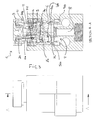
- a device 1 for adjusting water according to the present invention is schematically represented in exploded form, and in particular a device for adjusting water in a shower or in a bathroom or kitchen sink.
- the device may be mounted on a shower panel or worktop of the kitchen or bathroom sink and has the function of opening and closing the water and adjusting the flowrate and the temperature.
- the water is supplied via a diffuser in fluid communication with the device 1, for example a spray head mounted in a fixed or removable manner on the shower panel or a diffuser nozzle mounted on the sink.
- Figure 1 represents a pushbutton 7, a knob 10, a body 5, a shutter 2, a disk 3 and a second body 6 of the device 1 according to the invention.
- the pushbutton 7 is adapted to receive the manual pressure by the operator.
- the device 1 is preferably able to be mounted, in a concealed manner, with the only pushbutton 7 and the knob 10 visible and facing the user, preferably flush with the worktop or the shower panel.
- the pushbutton 7 is associated to a pair of toothed wheels 7B, 7C and a spring 60, suitable to cooperate for positioning a magnet 4 in two different stable positions associated with successive operating actions of the pushbutton 7 along the axis X, as a consequence of a pressure on the pushbutton 7.
- the body 5 comprises a cylindrical chamber 5a with a blind end 55a, around which the magnet 4, the toothed wheel 7C, and along a predetermined section, the toothed wheel 7B are slidable.
- the spring 60 is arranged between the body 5 and the toothed wheel 7C containing the magnet 4.
- a threaded hollow body 11 forms a seat for a portion of the body 5, allowing another portion (the lower portion, in figure 1 ) of said body 5 projecting from the cylinder 11 to be coupled with the body 6.
- Means for coupling, for instance teeth 55b, 10b and recesses 66b, 11b, formed on peripheral parts of the body 5, of the knob 10, of the body 6 and of the threaded hollow body 11, are provided to block in rotation said components of the device.
- the magnet 4 is inserted inside the toothed wheel 7C and together with it onto the cylinder chamber 5a, inside the hollow cylinder 11.
- the teeth of the wheel 7B and the teeth of the wheel 7C cooperate so that successive pressures on the pushbutton 7displace the magnet 4 into a distal or proximal position of the cylindrical chamber 5a, distancing a metal part 2a of a shutter 2, associated to the magnet 4, from a base 55a of the cylindrical chamber or approaching it to the base.
- Said displacement in a proximal or distal position is millimeter and thus requires only a light pressure on the pushbutton.
- the shutter 2 engages with the bottom part of the cylindrical chamber 5a, inside it, and has at least a distal part 2c projecting from the cylindrical chamber 5a.
- the shutter 2 engages with the top part of the cylindrical chamber 5a, i.e. towards the base 55a, still inside it, and is retracted inside the cylindrical chamber 5a.
- the shutter 2 comprises a seal 2c, which is mounted on the distal part 2c and designed to close a hole 3c in the disk 3, and a plastic spacer 2b.
- the shutter 2 has a metal core 2A, on which the seal 2c is mounted in a distal position and the plastic spacer 2b, along a central section, leaving only the metal part 2a at the end of the shutter exposed to the force of attraction of the magnet 4.
- the spacer 2c allow the dimensions of the magnet, and therefore of the device 1, to be reduced.
- the pushbutton 7 is configured to return into the same position, before and after closing or opening of the water flow, i.e. after actuation along the axis X.
- the displacement of the shutter is of few millimetres and merely has the function of triggering a displacement of a fluid shut-off disk 3, which is intended to actually close and open the water flow through the device.
- a very light pressure on the pushbutton 7 brings the shutter 2 into contact with the disk 3 or moves the shutter 2 away from the disk 3 and allow, respectively, that the filling or emptying of the chamber 5 determines displacement of the disk 3, respectively, to closure or opening of the water flow.
- Full opening of flow corresponds to a maximum distance of the shutter of the disk 3.
- Full closure of the flow is obtained by bringing the shutter into contact with the disk 3.
- the disk 3 comprises an elastically deformable membrane 3a and a rigid washer 3B on which the membrane is mounted.
- the disk 3 is mounted between the body 5 and a second body 6 and acts as a seal between them.
- the bodies 5 and 6 are fixed together and delimit the chamber 5 within which the disk 3 moves.
- the body 6 is associated with the inlets 9 and 9b of hot and cold water of the device and with an output 8.
- the inlets 9, 9b are adapted to receive water under pressure, for example at a pressure between 0.1 and 10 bar coming from the distribution network.
- the disk 3 is provided with a hole 3d in fluid communication with the inlets 9, 9b and a hole 3c in fluid communication with the outlet 8.
- the disk 3 is subject to the pressure of the incoming water (from the top to the bottom in Figure 3 ) which has the effect of displacing the disk downwards.
- the water may pass , filling the space between the disk 3 and the body 5 and pushing the disk 3 on the outlet 8, with partial deformation of the membrane 3a, in order to close the flow.
- the seal 2c of the shutter closes off the central hole 3c of the rigid washer, thus allowing the pressure of the water (from the top downwards in Figure 3 ) which pushes the membrane and the rigid washer against the outlet 8 to be greater than the pressure of the incoming water 9.
- the shutter 2 projects from the cylindrical chamber 5a and makes contact with the disk 3.
- a chamber 5b is provided in the body 5, in fluid communication with the inlets and the outlet 8, inside which chamber the disk 3 is movable.
- the disk 3 is configured to move to intercept the water flow to the outlet 8 as a result of filling of the chamber 5b, when the hole 3c is closed off by the shutter 2, or to open the outlet 9, as a result of emptying of the chamber 5a, when the hole 3c is freed by the shutter 2.
- Figure 2 is a cross-sectional view of the device 1, in which the shutter 2 is retracted inside the cylindrical chamber 5a and spaced from the disk 3, leaving the hole 3c in the disk 3free.
- the water which enters into the chamber 5b through the hole 3d may pass out from the chamber 5b, through the hole 3c, and at the same time may exert a pressure on the disk 3 (from the bottom upwards, in Figure 2 ) which raises the disk from the outlet 8, therefore allowing water to pass through the outlet 8.
- the shutter 2 When the shutter 2 is displaced against the disk 3, it has the function of closing the hole 3c, preventing the water from flowing out of the hole 3c and causing a fast filling of the chamber 5b, thus increasing the pressure of the water (from the top downwards) on the disk 3, pushing it against the outlet 8.
- the cylindrical chamber 5a has a diameter substantially equal to diameter of the shutter and is in fluid communication with the chamber 5b.
- the cylindrical chamber has a length of between 10 and 16 mm and a diameter of between 5 and 10 mm.
- the chamber 5a has a diameter of between 5 and 8 mm.
- the shutter in the cylindrical chamber is not subject to a high water pressure and, advantageously, may be easily displaced inside the chamber 5a.
- the user exerts on the shutter 2 only a pressure needed to cause projection of the shutter from the cylindrical chamber 5a and contact thereof with the disk 3, to close the water, or retraction thereof inside the cylindrical chamber 5b and separation from the disk 3, in order to open the flow.
- the rigid washer 3b comprises preferably a shank in the form of a cross 3E or star 3E which can be inserted into the outlet 8; the width of the cross of the shank or the star is substantially the same as a diameter of the outlet 8.
- the washer also comprises a head 3F with a diameter greater than the outlet 8, acting as a plug; the hole 3D is situated on a peripheral part of the head 3F which does not involve the plug.
- the hole 3C has a diameter smaller than the diameter of the outlet 8; when the hole 3C is freed by the shutter, the water flows out of the outlet 8 without entering into the chamber 5a.
- the pushbutton 7 is rotatable about the axis X, in order to vary the open position of the shutter 2 along the axis X and to vary a corresponding flow rate.
- the opening position of the shutter 2 which corresponds to a more retracted position A of the shutter towards the bottom 55a of the chamber 5a with respect to a closing position B, can be adjusted by rotation of the button 7, bringing the shutter in a position A1 of opening more advanced or more retracted of the position A and, respectively, more or less interfering in the fluid path from the inlets 9 to the outlet 8.
- an externally threaded ring 20 is engaged in a threaded portion of the hollow cylinder 11 and is rotatable by means of the pushbutton 7, so as to engage with a larger or smaller portion of the hollow cylinder 11.
- the button 7 is coupled to the ring 20 via a body 12 having a base 122, a cylinder 123 on the base, and at least one tab 77 on the outside of the cylinder 123, adapted to slide in a respective groove 222 located on the inner surface of the ring 20, for solidarity in rotation the ring 20, the body 12 and the button 7. Between the cylinder 123 and the tab 77 is inserted a cylindrical portion 7BC of the toothed wheel 7B which is in contact with the base.
- the tab 77 passing through the threaded ring 20 is configured to exert a pressure on the toothed wheel 7C which regulates the position of the magnet 4.
- Screwing the knob 7 or unscrewing thereof from the hollow cylinder 11 may be performed during delivery of the flow, and therefore adjusting the flowrate of the water during supply, or when the water is closed, and therefore adjusting or resetting the flowrate before the supply.
- Means are envisaged for limiting rotation of the pushbutton 7 about the axis X, preferably limiting the rotation to 180°, for example by means of a locating shoulder 78 or a stop element 78 in the pushbutton 7D.
- a knob 10 for adjusting the temperature is integrally coupled in rotation to the hollow cylinder 11, the bodies 5 and 6, and a disc shutter 400 , having a central outlet hole 401 and one or more peripheral holes 402.
- the disc shutter 400 is rotatable around the axis X to vary a ratio between the quantity of hot water and cold water input from the respective inlets 9, 9b, according to an angular displacement with respect to a fixed disk 900, delimiting the inlets 9, 9b .
- the disc shutter 400 is made of ceramic material and the fixed disk 900 is made of plastic material. Among the shutter disk 400 and the hard disk 900 is interposed a ceramic disc 500, having substantially the same configuration of inlets and outlets of the hard disk 900.
- the maximum water temperature is obtained by aligning the peripheral hole(s) to the inlet of hot water.
- the minimum temperature is obtained by aligning the peripheral hole (s) to the inlet of cold water.
- Intermediate temperatures are obtained by placing the disc shutter to receive water in part from the inlet of hot water and in from the inlet of cold water, in equal or different extent.
Landscapes
- Engineering & Computer Science (AREA)
- General Engineering & Computer Science (AREA)
- Mechanical Engineering (AREA)
- Nozzles (AREA)
- Domestic Plumbing Installations (AREA)
Priority Applications (3)
| Application Number | Priority Date | Filing Date | Title |
|---|---|---|---|
| EP14155396.6A EP2865929B1 (de) | 2013-10-25 | 2014-02-17 | Vorrichtung zur Einstellung des Wassers in einer Dusche oder Bad oder Küchenwaschbecken |
| US14/242,668 US9297475B2 (en) | 2013-10-25 | 2014-04-01 | System for adjusting water in a shower, bathroom, or kitchen sink |
| CN201410265111.5A CN104565432B (zh) | 2013-10-25 | 2014-06-13 | 用于调节淋浴器或浴室水槽或厨房水槽中的水的系统 |
Applications Claiming Priority (2)
| Application Number | Priority Date | Filing Date | Title |
|---|---|---|---|
| EP13190336 | 2013-10-25 | ||
| EP14155396.6A EP2865929B1 (de) | 2013-10-25 | 2014-02-17 | Vorrichtung zur Einstellung des Wassers in einer Dusche oder Bad oder Küchenwaschbecken |
Publications (2)
| Publication Number | Publication Date |
|---|---|
| EP2865929A1 true EP2865929A1 (de) | 2015-04-29 |
| EP2865929B1 EP2865929B1 (de) | 2017-01-25 |
Family
ID=55486364
Family Applications (1)
| Application Number | Title | Priority Date | Filing Date |
|---|---|---|---|
| EP14155396.6A Active EP2865929B1 (de) | 2013-10-25 | 2014-02-17 | Vorrichtung zur Einstellung des Wassers in einer Dusche oder Bad oder Küchenwaschbecken |
Country Status (3)
| Country | Link |
|---|---|
| US (1) | US9297475B2 (de) |
| EP (1) | EP2865929B1 (de) |
| CN (1) | CN104565432B (de) |
Cited By (8)
| Publication number | Priority date | Publication date | Assignee | Title |
|---|---|---|---|---|
| WO2017144169A1 (de) * | 2016-02-22 | 2017-08-31 | Neoperl Gmbh | Ventilbetätigungsvorrichtung |
| CN107345588A (zh) * | 2016-05-04 | 2017-11-14 | 温州阿母斯丹洁具科技有限公司 | 一种按钮带调温旋钮的延时自闭式节水龙头 |
| EP3309306A3 (de) * | 2016-10-14 | 2018-05-16 | Hongxin Lin | Kombinierte dusche |
| DE102017107527B3 (de) | 2017-04-07 | 2018-09-20 | Kludi Gmbh & Co. Kg | Sanitärventil mit wenigstens einem Wasserschalter |
| CN114382930A (zh) * | 2022-03-26 | 2022-04-22 | 艾肯(江苏)工业技术有限公司 | 一种防密封件膨胀的耐高温蒸汽分配阀组 |
| WO2022175196A1 (de) * | 2021-02-19 | 2022-08-25 | Neoperl Gmbh | Sanitärventil |
| WO2022175431A1 (de) * | 2021-02-19 | 2022-08-25 | Neoperl Gmbh | Sanitärventil |
| WO2024047520A1 (en) * | 2022-08-30 | 2024-03-07 | Fabrizio Nobili | Dispensing device for water-dispensing units |
Families Citing this family (13)
| Publication number | Priority date | Publication date | Assignee | Title |
|---|---|---|---|---|
| EP3147546B1 (de) | 2015-09-25 | 2017-11-08 | Fabrizio Nobili | Vorrichtung zum öffnen, schliessen und regeln der durchflussrate für einen armaturenkörper eines bades oder einer küche |
| EP3537015B1 (de) * | 2016-11-07 | 2021-07-14 | Xiamen Solex High-Tech Industries Co., Ltd. | Schaltventilkern für wasserabsperrung |
| CN106641277B (zh) * | 2016-12-01 | 2020-05-05 | 北京科勒有限公司 | 开关阀 |
| DE102017100711A1 (de) * | 2017-01-16 | 2018-07-19 | Grohe Ag | Unterputzeinbaukörper für eine Sanitärarmatur mit einem axial verstellbaren Drehgriff |
| DE102017100709A1 (de) * | 2017-01-16 | 2018-07-19 | Grohe Ag | Ventil für einen Unterputzeinbaukörper einer Sanitärarmatur mit einem drehbar an einem Ventilknopf befestigten Betätigungsknopf |
| DE102017100708A1 (de) * | 2017-01-16 | 2018-07-19 | Grohe Ag | Unterputzeinbaukörper für eine Sanitärarmatur mit zumindest einem variabel positionierbaren Druckknopf |
| DE202017101403U1 (de) * | 2017-03-10 | 2018-06-12 | Neoperl Gmbh | Sanitärventil und korrespondierende Baureihe |
| CN208687007U (zh) * | 2018-06-27 | 2019-04-02 | 北京科勒有限公司 | 流量调节开关阀 |
| DE102019103609A1 (de) * | 2019-02-13 | 2020-08-13 | Grohe Ag | Ventil für einen Unterputzeinbaukörper einer Sanitärarmatur |
| DE102019103610A1 (de) * | 2019-02-13 | 2020-08-13 | Grohe Ag | Ventil für einen Unterputzeinbaukörper einer Sanitärarmatur mit einem Mengenregulierteil und einem Temperaturregulierteil |
| EP3736474B1 (de) * | 2019-05-09 | 2022-02-23 | Carrier Corporation | Magnetventilsperre |
| US20200362973A1 (en) * | 2019-05-14 | 2020-11-19 | Tecan Trading Ag | Non-sticking rotary valve |
| EP4141303A1 (de) * | 2021-08-26 | 2023-03-01 | Fabrizio Nobili | Ventilbetätigungsvorrichtung |
Citations (5)
| Publication number | Priority date | Publication date | Assignee | Title |
|---|---|---|---|---|
| GB2103391A (en) * | 1981-07-31 | 1983-02-16 | Peglers Ltd | Servo operated fluid flow taps and valves |
| EP0183102A1 (de) * | 1984-11-15 | 1986-06-04 | FRIEDRICH GROHE ARMATURENFABRIK GmbH & CO | Vorrichtung zur Füllmengensteuerung |
| DE4341620A1 (de) * | 1993-12-07 | 1995-06-08 | Grohe Armaturen Friedrich | Selbstschlußventil |
| DE4341650A1 (de) * | 1993-12-07 | 1995-06-08 | Grohe Armaturen Friedrich | Selbstschlußventil |
| EP0831260A2 (de) * | 1996-09-18 | 1998-03-25 | Oras Oy | Mischventil mit Temperatursteuerung |
Family Cites Families (10)
| Publication number | Priority date | Publication date | Assignee | Title |
|---|---|---|---|---|
| US2629401A (en) * | 1947-10-08 | 1953-02-24 | Hays Mfg Co | Magnetically controlled packless valve |
| DE3109943A1 (de) | 1981-03-14 | 1982-10-07 | Rotter GmbH & Co KG, 1000 Berlin | Permanentmagnetisch gesteuertes selbstschlussventil |
| US5169117A (en) * | 1992-02-27 | 1992-12-08 | Huang Chi King | Low power type, motor-controlled magnetic valve |
| FR2727736B1 (fr) * | 1994-12-02 | 1997-01-24 | Eaton Sa Monaco | Vanne commandee par un fluide |
| JP4142219B2 (ja) | 1999-09-29 | 2008-09-03 | 株式会社Inax | 吐水装置 |
| US6607174B2 (en) * | 2001-10-17 | 2003-08-19 | Dema Engineering Company | Dispensing apparatus with in-line actuator |
| AU2003261872A1 (en) * | 2002-08-30 | 2004-03-19 | Toto Ltd. | Opening and closing valve |
| AU2007295959A1 (en) * | 2006-09-15 | 2008-03-20 | Ken Harrison | An apparatus for controlling fluid flow |
| IT1403610B1 (it) * | 2010-12-22 | 2013-10-31 | Ruga | Valvola miscelatrice termostatica con deviatore di flusso incorporato |
| DE102012221043A1 (de) | 2012-11-19 | 2014-05-22 | Hansgrohe Se | Sanitärventil |
-
2014
- 2014-02-17 EP EP14155396.6A patent/EP2865929B1/de active Active
- 2014-04-01 US US14/242,668 patent/US9297475B2/en active Active
- 2014-06-13 CN CN201410265111.5A patent/CN104565432B/zh active Active
Patent Citations (5)
| Publication number | Priority date | Publication date | Assignee | Title |
|---|---|---|---|---|
| GB2103391A (en) * | 1981-07-31 | 1983-02-16 | Peglers Ltd | Servo operated fluid flow taps and valves |
| EP0183102A1 (de) * | 1984-11-15 | 1986-06-04 | FRIEDRICH GROHE ARMATURENFABRIK GmbH & CO | Vorrichtung zur Füllmengensteuerung |
| DE4341620A1 (de) * | 1993-12-07 | 1995-06-08 | Grohe Armaturen Friedrich | Selbstschlußventil |
| DE4341650A1 (de) * | 1993-12-07 | 1995-06-08 | Grohe Armaturen Friedrich | Selbstschlußventil |
| EP0831260A2 (de) * | 1996-09-18 | 1998-03-25 | Oras Oy | Mischventil mit Temperatursteuerung |
Cited By (17)
| Publication number | Priority date | Publication date | Assignee | Title |
|---|---|---|---|---|
| EP3420258B1 (de) | 2016-02-22 | 2020-02-12 | Neoperl GmbH | Ventilbetätigungsvorrichtung |
| EP3514427A1 (de) * | 2016-02-22 | 2019-07-24 | Neoperl GmbH | Ventilbetätigungsvorrichtung |
| WO2017144169A1 (de) * | 2016-02-22 | 2017-08-31 | Neoperl Gmbh | Ventilbetätigungsvorrichtung |
| EP4219990A3 (de) * | 2016-02-22 | 2023-10-18 | Neoperl GmbH | Ventilbetätigungsvorrichtung |
| EP3420258B2 (de) † | 2016-02-22 | 2023-06-28 | Neoperl GmbH | Ventilbetätigungsvorrichtung |
| EP3514426A1 (de) * | 2016-02-22 | 2019-07-24 | Neoperl GmbH | Ventilbetätigungsvorrichtung |
| EP3514425A1 (de) * | 2016-02-22 | 2019-07-24 | Neoperl GmbH | Ventilbetätigungsvorrichtung |
| US11408534B2 (en) | 2016-02-22 | 2022-08-09 | Neoperl Gmbh | Valve-actuating device |
| EP3521672A1 (de) * | 2016-02-22 | 2019-08-07 | Neoperl GmbH | Ventilbetätigungsvorrichtung |
| CN107345588A (zh) * | 2016-05-04 | 2017-11-14 | 温州阿母斯丹洁具科技有限公司 | 一种按钮带调温旋钮的延时自闭式节水龙头 |
| EP3309306A3 (de) * | 2016-10-14 | 2018-05-16 | Hongxin Lin | Kombinierte dusche |
| DE102017107527B3 (de) | 2017-04-07 | 2018-09-20 | Kludi Gmbh & Co. Kg | Sanitärventil mit wenigstens einem Wasserschalter |
| WO2022175196A1 (de) * | 2021-02-19 | 2022-08-25 | Neoperl Gmbh | Sanitärventil |
| WO2022175431A1 (de) * | 2021-02-19 | 2022-08-25 | Neoperl Gmbh | Sanitärventil |
| CN114382930B (zh) * | 2022-03-26 | 2022-07-01 | 艾肯(江苏)工业技术有限公司 | 一种防密封件膨胀的耐高温蒸汽分配阀组 |
| CN114382930A (zh) * | 2022-03-26 | 2022-04-22 | 艾肯(江苏)工业技术有限公司 | 一种防密封件膨胀的耐高温蒸汽分配阀组 |
| WO2024047520A1 (en) * | 2022-08-30 | 2024-03-07 | Fabrizio Nobili | Dispensing device for water-dispensing units |
Also Published As
| Publication number | Publication date |
|---|---|
| EP2865929B1 (de) | 2017-01-25 |
| CN104565432B (zh) | 2019-03-26 |
| US20150115183A1 (en) | 2015-04-30 |
| CN104565432A (zh) | 2015-04-29 |
| US9297475B2 (en) | 2016-03-29 |
Similar Documents
| Publication | Publication Date | Title |
|---|---|---|
| EP2865929B1 (de) | Vorrichtung zur Einstellung des Wassers in einer Dusche oder Bad oder Küchenwaschbecken | |
| EP2865928B1 (de) | Ventil | |
| CN107023689B (zh) | 打开、闭合浴室或厨房的水嘴体和调节水嘴体的流速的装置 | |
| US10808857B2 (en) | Multifunctional restrictive valve | |
| US8464962B2 (en) | 3-stage temperature control valve | |
| US9737899B2 (en) | Water control system having a temperature controlled tub faucet valve | |
| CN109899588B (zh) | 阀致动装置和卫生阀 | |
| EP3189257B1 (de) | Absperrventil sowie verwendung eines solchen absperrventils | |
| JP4137316B2 (ja) | 吐水装置 | |
| EP2054653B1 (de) | Verbesserungen von wasserhahnadaptern oder diese betreffend | |
| US20210180621A1 (en) | Valve arrangement | |
| EP3587880B1 (de) | Stromsteuerschaltventil | |
| JP2001095709A (ja) | 吐水装置 | |
| US3601141A (en) | Changeover valve | |
| WO2019225132A1 (ja) | スプリング式タイマー | |
| WO2011155907A1 (fr) | Dispositif de fermeture automatique temporisée | |
| JP2005155797A (ja) | 水栓装置 | |
| US1775499A (en) | Cam faucet | |
| US11867313B2 (en) | Adjustment device for a water delivery unit | |
| JP2011144559A (ja) | 水栓システム | |
| KR102016508B1 (ko) | 출수 시간 조절이 가능한 절수형 자폐 밸브 장치 | |
| JP4116742B2 (ja) | 吐水装置 | |
| IT202100004253U1 (it) | Dispositivo di regolazione per unita’ di erogazione-acqua | |
| TWM471523U (zh) | 複合式控水軸 | |
| JP2000213017A (ja) | 吐水具 |
Legal Events
| Date | Code | Title | Description |
|---|---|---|---|
| PUAI | Public reference made under article 153(3) epc to a published international application that has entered the european phase |
Free format text: ORIGINAL CODE: 0009012 |
|
| 17P | Request for examination filed |
Effective date: 20140217 |
|
| AK | Designated contracting states |
Kind code of ref document: A1 Designated state(s): AL AT BE BG CH CY CZ DE DK EE ES FI FR GB GR HR HU IE IS IT LI LT LU LV MC MK MT NL NO PL PT RO RS SE SI SK SM TR |
|
| AX | Request for extension of the european patent |
Extension state: BA ME |
|
| R17P | Request for examination filed (corrected) |
Effective date: 20150821 |
|
| RBV | Designated contracting states (corrected) |
Designated state(s): AL AT BE BG CH CY CZ DE DK EE ES FI FR GB GR HR HU IE IS IT LI LT LU LV MC MK MT NL NO PL PT RO RS SE SI SK SM TR |
|
| 17Q | First examination report despatched |
Effective date: 20151217 |
|
| GRAP | Despatch of communication of intention to grant a patent |
Free format text: ORIGINAL CODE: EPIDOSNIGR1 |
|
| INTG | Intention to grant announced |
Effective date: 20160811 |
|
| GRAS | Grant fee paid |
Free format text: ORIGINAL CODE: EPIDOSNIGR3 |
|
| GRAA | (expected) grant |
Free format text: ORIGINAL CODE: 0009210 |
|
| AK | Designated contracting states |
Kind code of ref document: B1 Designated state(s): AL AT BE BG CH CY CZ DE DK EE ES FI FR GB GR HR HU IE IS IT LI LT LU LV MC MK MT NL NO PL PT RO RS SE SI SK SM TR |
|
| REG | Reference to a national code |
Ref country code: GB Ref legal event code: FG4D |
|
| REG | Reference to a national code |
Ref country code: CH Ref legal event code: EP |
|
| REG | Reference to a national code |
Ref country code: AT Ref legal event code: REF Ref document number: 864356 Country of ref document: AT Kind code of ref document: T Effective date: 20170215 |
|
| REG | Reference to a national code |
Ref country code: IE Ref legal event code: FG4D |
|
| REG | Reference to a national code |
Ref country code: DE Ref legal event code: R096 Ref document number: 602014006294 Country of ref document: DE |
|
| REG | Reference to a national code |
Ref country code: FR Ref legal event code: PLFP Year of fee payment: 4 |
|
| REG | Reference to a national code |
Ref country code: CH Ref legal event code: NV Representative=s name: ING. MARCO ZARDI C/O M. ZARDI AND CO. S.A., CH |
|
| REG | Reference to a national code |
Ref country code: LT Ref legal event code: MG4D |
|
| PG25 | Lapsed in a contracting state [announced via postgrant information from national office to epo] |
Ref country code: BE Free format text: LAPSE BECAUSE OF NON-PAYMENT OF DUE FEES Effective date: 20170228 |
|
| REG | Reference to a national code |
Ref country code: NL Ref legal event code: MP Effective date: 20170125 |
|
| PG25 | Lapsed in a contracting state [announced via postgrant information from national office to epo] |
Ref country code: NL Free format text: LAPSE BECAUSE OF FAILURE TO SUBMIT A TRANSLATION OF THE DESCRIPTION OR TO PAY THE FEE WITHIN THE PRESCRIBED TIME-LIMIT Effective date: 20170125 |
|
| REG | Reference to a national code |
Ref country code: ES Ref legal event code: FG2A Ref document number: 2621953 Country of ref document: ES Kind code of ref document: T3 Effective date: 20170705 |
|
| PG25 | Lapsed in a contracting state [announced via postgrant information from national office to epo] |
Ref country code: GR Free format text: LAPSE BECAUSE OF FAILURE TO SUBMIT A TRANSLATION OF THE DESCRIPTION OR TO PAY THE FEE WITHIN THE PRESCRIBED TIME-LIMIT Effective date: 20170426 Ref country code: HR Free format text: LAPSE BECAUSE OF FAILURE TO SUBMIT A TRANSLATION OF THE DESCRIPTION OR TO PAY THE FEE WITHIN THE PRESCRIBED TIME-LIMIT Effective date: 20170125 Ref country code: LT Free format text: LAPSE BECAUSE OF FAILURE TO SUBMIT A TRANSLATION OF THE DESCRIPTION OR TO PAY THE FEE WITHIN THE PRESCRIBED TIME-LIMIT Effective date: 20170125 Ref country code: NO Free format text: LAPSE BECAUSE OF FAILURE TO SUBMIT A TRANSLATION OF THE DESCRIPTION OR TO PAY THE FEE WITHIN THE PRESCRIBED TIME-LIMIT Effective date: 20170425 Ref country code: IS Free format text: LAPSE BECAUSE OF FAILURE TO SUBMIT A TRANSLATION OF THE DESCRIPTION OR TO PAY THE FEE WITHIN THE PRESCRIBED TIME-LIMIT Effective date: 20170525 |
|
| PG25 | Lapsed in a contracting state [announced via postgrant information from national office to epo] |
Ref country code: BG Free format text: LAPSE BECAUSE OF FAILURE TO SUBMIT A TRANSLATION OF THE DESCRIPTION OR TO PAY THE FEE WITHIN THE PRESCRIBED TIME-LIMIT Effective date: 20170425 Ref country code: RS Free format text: LAPSE BECAUSE OF FAILURE TO SUBMIT A TRANSLATION OF THE DESCRIPTION OR TO PAY THE FEE WITHIN THE PRESCRIBED TIME-LIMIT Effective date: 20170125 Ref country code: SE Free format text: LAPSE BECAUSE OF FAILURE TO SUBMIT A TRANSLATION OF THE DESCRIPTION OR TO PAY THE FEE WITHIN THE PRESCRIBED TIME-LIMIT Effective date: 20170125 Ref country code: LV Free format text: LAPSE BECAUSE OF FAILURE TO SUBMIT A TRANSLATION OF THE DESCRIPTION OR TO PAY THE FEE WITHIN THE PRESCRIBED TIME-LIMIT Effective date: 20170125 Ref country code: PL Free format text: LAPSE BECAUSE OF FAILURE TO SUBMIT A TRANSLATION OF THE DESCRIPTION OR TO PAY THE FEE WITHIN THE PRESCRIBED TIME-LIMIT Effective date: 20170125 Ref country code: PT Free format text: LAPSE BECAUSE OF FAILURE TO SUBMIT A TRANSLATION OF THE DESCRIPTION OR TO PAY THE FEE WITHIN THE PRESCRIBED TIME-LIMIT Effective date: 20170525 |
|
| REG | Reference to a national code |
Ref country code: DE Ref legal event code: R097 Ref document number: 602014006294 Country of ref document: DE |
|
| PG25 | Lapsed in a contracting state [announced via postgrant information from national office to epo] |
Ref country code: RO Free format text: LAPSE BECAUSE OF FAILURE TO SUBMIT A TRANSLATION OF THE DESCRIPTION OR TO PAY THE FEE WITHIN THE PRESCRIBED TIME-LIMIT Effective date: 20170125 Ref country code: EE Free format text: LAPSE BECAUSE OF FAILURE TO SUBMIT A TRANSLATION OF THE DESCRIPTION OR TO PAY THE FEE WITHIN THE PRESCRIBED TIME-LIMIT Effective date: 20170125 Ref country code: SK Free format text: LAPSE BECAUSE OF FAILURE TO SUBMIT A TRANSLATION OF THE DESCRIPTION OR TO PAY THE FEE WITHIN THE PRESCRIBED TIME-LIMIT Effective date: 20170125 |
|
| REG | Reference to a national code |
Ref country code: IE Ref legal event code: MM4A |
|
| PG25 | Lapsed in a contracting state [announced via postgrant information from national office to epo] |
Ref country code: SM Free format text: LAPSE BECAUSE OF FAILURE TO SUBMIT A TRANSLATION OF THE DESCRIPTION OR TO PAY THE FEE WITHIN THE PRESCRIBED TIME-LIMIT Effective date: 20170125 Ref country code: MC Free format text: LAPSE BECAUSE OF FAILURE TO SUBMIT A TRANSLATION OF THE DESCRIPTION OR TO PAY THE FEE WITHIN THE PRESCRIBED TIME-LIMIT Effective date: 20170125 Ref country code: DK Free format text: LAPSE BECAUSE OF FAILURE TO SUBMIT A TRANSLATION OF THE DESCRIPTION OR TO PAY THE FEE WITHIN THE PRESCRIBED TIME-LIMIT Effective date: 20170125 |
|
| PLBE | No opposition filed within time limit |
Free format text: ORIGINAL CODE: 0009261 |
|
| STAA | Information on the status of an ep patent application or granted ep patent |
Free format text: STATUS: NO OPPOSITION FILED WITHIN TIME LIMIT |
|
| PG25 | Lapsed in a contracting state [announced via postgrant information from national office to epo] |
Ref country code: LU Free format text: LAPSE BECAUSE OF NON-PAYMENT OF DUE FEES Effective date: 20170217 |
|
| 26N | No opposition filed |
Effective date: 20171026 |
|
| REG | Reference to a national code |
Ref country code: BE Ref legal event code: MM Effective date: 20170228 |
|
| REG | Reference to a national code |
Ref country code: FR Ref legal event code: PLFP Year of fee payment: 5 |
|
| PG25 | Lapsed in a contracting state [announced via postgrant information from national office to epo] |
Ref country code: IE Free format text: LAPSE BECAUSE OF NON-PAYMENT OF DUE FEES Effective date: 20170217 Ref country code: SI Free format text: LAPSE BECAUSE OF FAILURE TO SUBMIT A TRANSLATION OF THE DESCRIPTION OR TO PAY THE FEE WITHIN THE PRESCRIBED TIME-LIMIT Effective date: 20170125 |
|
| PG25 | Lapsed in a contracting state [announced via postgrant information from national office to epo] |
Ref country code: MT Free format text: LAPSE BECAUSE OF NON-PAYMENT OF DUE FEES Effective date: 20170217 |
|
| REG | Reference to a national code |
Ref country code: DE Ref legal event code: R082 Ref document number: 602014006294 Country of ref document: DE Representative=s name: HGF EUROPE LLP, DE Ref country code: DE Ref legal event code: R082 Ref document number: 602014006294 Country of ref document: DE Representative=s name: HGF EUROPE LP, DE |
|
| PG25 | Lapsed in a contracting state [announced via postgrant information from national office to epo] |
Ref country code: HU Free format text: LAPSE BECAUSE OF FAILURE TO SUBMIT A TRANSLATION OF THE DESCRIPTION OR TO PAY THE FEE WITHIN THE PRESCRIBED TIME-LIMIT; INVALID AB INITIO Effective date: 20140217 |
|
| PG25 | Lapsed in a contracting state [announced via postgrant information from national office to epo] |
Ref country code: CY Free format text: LAPSE BECAUSE OF FAILURE TO SUBMIT A TRANSLATION OF THE DESCRIPTION OR TO PAY THE FEE WITHIN THE PRESCRIBED TIME-LIMIT Effective date: 20170125 |
|
| PG25 | Lapsed in a contracting state [announced via postgrant information from national office to epo] |
Ref country code: MK Free format text: LAPSE BECAUSE OF FAILURE TO SUBMIT A TRANSLATION OF THE DESCRIPTION OR TO PAY THE FEE WITHIN THE PRESCRIBED TIME-LIMIT Effective date: 20170125 |
|
| PG25 | Lapsed in a contracting state [announced via postgrant information from national office to epo] |
Ref country code: AL Free format text: LAPSE BECAUSE OF FAILURE TO SUBMIT A TRANSLATION OF THE DESCRIPTION OR TO PAY THE FEE WITHIN THE PRESCRIBED TIME-LIMIT Effective date: 20170125 |
|
| REG | Reference to a national code |
Ref country code: AT Ref legal event code: UEP Ref document number: 864356 Country of ref document: AT Kind code of ref document: T Effective date: 20170125 |
|
| PGFP | Annual fee paid to national office [announced via postgrant information from national office to epo] |
Ref country code: FR Payment date: 20230223 Year of fee payment: 10 |
|
| PGFP | Annual fee paid to national office [announced via postgrant information from national office to epo] |
Ref country code: TR Payment date: 20230210 Year of fee payment: 10 Ref country code: IT Payment date: 20230221 Year of fee payment: 10 |
|
| PGFP | Annual fee paid to national office [announced via postgrant information from national office to epo] |
Ref country code: ES Payment date: 20240301 Year of fee payment: 11 |
|
| PGFP | Annual fee paid to national office [announced via postgrant information from national office to epo] |
Ref country code: AT Payment date: 20240221 Year of fee payment: 11 |
|
| PGFP | Annual fee paid to national office [announced via postgrant information from national office to epo] |
Ref country code: FI Payment date: 20240226 Year of fee payment: 11 Ref country code: DE Payment date: 20240228 Year of fee payment: 11 Ref country code: CZ Payment date: 20240221 Year of fee payment: 11 Ref country code: CH Payment date: 20240301 Year of fee payment: 11 Ref country code: GB Payment date: 20240227 Year of fee payment: 11 |