EP2865476A2 - Lichtbogenschweißvorrichtung, Lichtbogenschweißverfahren und geschweißter Gegenstand - Google Patents
Lichtbogenschweißvorrichtung, Lichtbogenschweißverfahren und geschweißter Gegenstand Download PDFInfo
- Publication number
- EP2865476A2 EP2865476A2 EP20140184394 EP14184394A EP2865476A2 EP 2865476 A2 EP2865476 A2 EP 2865476A2 EP 20140184394 EP20140184394 EP 20140184394 EP 14184394 A EP14184394 A EP 14184394A EP 2865476 A2 EP2865476 A2 EP 2865476A2
- Authority
- EP
- European Patent Office
- Prior art keywords
- arc
- state
- welding
- consumable electrode
- detected
- Prior art date
- Legal status (The legal status is an assumption and is not a legal conclusion. Google has not performed a legal analysis and makes no representation as to the accuracy of the status listed.)
- Granted
Links
Images
Classifications
-
- B—PERFORMING OPERATIONS; TRANSPORTING
- B23—MACHINE TOOLS; METAL-WORKING NOT OTHERWISE PROVIDED FOR
- B23K—SOLDERING OR UNSOLDERING; WELDING; CLADDING OR PLATING BY SOLDERING OR WELDING; CUTTING BY APPLYING HEAT LOCALLY, e.g. FLAME CUTTING; WORKING BY LASER BEAM
- B23K9/00—Arc welding or cutting
- B23K9/12—Automatic feeding or moving of electrodes or work for spot or seam welding or cutting
- B23K9/124—Circuits or methods for feeding welding wire
- B23K9/125—Feeding of electrodes
-
- B—PERFORMING OPERATIONS; TRANSPORTING
- B23—MACHINE TOOLS; METAL-WORKING NOT OTHERWISE PROVIDED FOR
- B23K—SOLDERING OR UNSOLDERING; WELDING; CLADDING OR PLATING BY SOLDERING OR WELDING; CUTTING BY APPLYING HEAT LOCALLY, e.g. FLAME CUTTING; WORKING BY LASER BEAM
- B23K9/00—Arc welding or cutting
- B23K9/09—Arrangements or circuits for arc welding with pulsed current or voltage
- B23K9/091—Arrangements or circuits for arc welding with pulsed current or voltage characterised by the circuits
-
- B—PERFORMING OPERATIONS; TRANSPORTING
- B23—MACHINE TOOLS; METAL-WORKING NOT OTHERWISE PROVIDED FOR
- B23K—SOLDERING OR UNSOLDERING; WELDING; CLADDING OR PLATING BY SOLDERING OR WELDING; CUTTING BY APPLYING HEAT LOCALLY, e.g. FLAME CUTTING; WORKING BY LASER BEAM
- B23K9/00—Arc welding or cutting
- B23K9/095—Monitoring or automatic control of welding parameters
-
- B—PERFORMING OPERATIONS; TRANSPORTING
- B23—MACHINE TOOLS; METAL-WORKING NOT OTHERWISE PROVIDED FOR
- B23K—SOLDERING OR UNSOLDERING; WELDING; CLADDING OR PLATING BY SOLDERING OR WELDING; CUTTING BY APPLYING HEAT LOCALLY, e.g. FLAME CUTTING; WORKING BY LASER BEAM
- B23K9/00—Arc welding or cutting
- B23K9/16—Arc welding or cutting making use of shielding gas
- B23K9/173—Arc welding or cutting making use of shielding gas and of a consumable electrode
Definitions
- Disclosed embodiments relate to an arc welding apparatus, an arc welding method, an arc welding system, and a welded article.
- An arc welding apparatus disclosed in Japanese Patent No. 4807474 intends to improve the welding quality by controlling the feeding direction to the welding wire. Feeding the welding wire in the direction to the base metal (the work) is called as “forward feed” and feeding the welding wire in the direction opposite to the base metal is called as "reverse feed”.
- the arc welding apparatus of Japanese Patent No. 4807474 suppresses the increase of the spatter by reverse-feeding the welding wire until a short is opened regardless of the welding frequency.
- One form of the embodiments has been achieved in view of the above.
- One of the purposes of one form of the embodiments is to provide an arc welding apparatus, an arc welding method, an arc welding system, and a welded article that can improve the welding quality.
- An arc welding apparatus includes: a detection unit configured to detect whether it is in a short state or an arc state between a consumable electrode and a welded article; a feed adjustment unit configured to adjust a feeding state of the consumable electrode so as to apply a forward feed for feeding the consumable electrode in a direction to the welded article when the detection unit detects the arc state and apply a reverse feed for feeding the consumable electrode in a direction opposite to the welded article when the detection unit detects the short state; a determination unit configured to determine whether or not a predetermined period has elapsed after the detection unit has detected the short state; and an instruction unit configured to instruct the feed adjustment unit to continue the reverse feed even when the detection unit detects the arc state, until the determination unit determines that the predetermined period has elapsed after the detection unit has detected the short state.
- An arc welding apparatus includes a detection unit, a feed adjustment unit, a determination unit, and an instruction unit.
- the detection unit detects whether it is in a short state or an arc state between a consumable electrode and a welded article.
- the feed adjustment unit adjusts a feeding state of the consumable electrode so as to apply a forward feed for feeding the consumable electrode in a direction to the welded article when the detection unit detects the arc state and apply a reverse feed for feeding the consumable electrode in a direction opposite to the welded article when the detection unit detects the short state.
- the determination unit determines whether or not a predetermined period has elapsed after the detection unit has detected the short state. Until the determination unit determines that the predetermined period has elapsed after the detection unit has detected the short state, the instruction unit instructs the feed adjustment unit to continue the reverse feed even when the detection unit detects the arc state.
- the welding quality can be improved.
- An arc welding apparatus 1 continues the reverse feed until at least a predetermined period has elapsed regardless of whether it is in a short state or an arc state. This allows for the improvement of the welding quality.
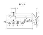
- FIG. 1 is a diagram illustrating a configuration of the arc welding apparatus 1 according to the first embodiment.
- the arc welding apparatus 1 has a primary rectifying circuit 3, a welding controller 4, a switching circuit 5, a transformer 6, a secondary rectifying circuit 7, a reactor 8, a current detector 9, a voltage detector 10, and a storage 17.
- the arc welding apparatus 1 supplies electric power for the welding to a welding torch 13 and a welded article (a work) W.
- the primary rectifying circuit 3 is connected to a source power supply 2. Further, the primary rectifying circuit 3 rectifies alternating power supplied from the source power supply 2. Further, the primary rectifying circuit 3 supplies the rectified power to the switching circuit 5.
- the switching circuit 5 applies a PWM control to the electric power supplied from the primary rectifying circuit 3 to generate power supply to be supplied to the welding torch 13. Further, the switching circuit 5 outputs the generated power supply to the transformer 6.
- the transformer 6 transforms the power supply voltage. Further, the transformer 6 outputs the transformed power supply to the secondary rectifying circuit 7.
- the secondary rectifying circuit 7 rectifies the power supply outputted from the transformer 6. Further, the secondary rectifying circuit 7 is connected to the work W via an output terminal 12.
- the reactor 8 smoothes the power supply rectified by the secondary rectifying circuit 7. Further, the reactor 8 is connected to the welding torch 13 via an output terminal 11. The power supply smoothed by the reactor 8 is supplied to the welding torch 13 and the work W via the output terminals 11 and 12.
- the current detector 9 detects the current between the welding torch 13 and the work W (hereafter, referred to as “welding current”). Further, the current detector 9 outputs the detected result to the welding controller 4.
- the voltage detector 10 detects the voltage between the welding torch 13 and the work W (hereafter, referred to as “welding voltage”). Further, the voltage detector 10 outputs the detected result to the welding controller 4.
- the welding controller 4 controls the switching circuit 5 and a feeding device 15 based on the detected result inputted from the current detector 9 and the voltage detector 10 and the instruction inputted from an external controller 16. Further, the welding controller 4 outputs information regarding the welding such as the welding current, the welding voltage, and the like to the external controller 16. The details of the welding controller 4 will be described later.
- the welding torch 13 supplies the welding current to a welding wire (a consumable electrode) 14.
- the feeding device 15 has an actuator such as a servo motor, for example. Further, the feeding device 15 applies a forward feed and a reverse feed of the welding wire 14 based on the instruction from the welding controller 4.
- the forward feed refers to the feeding of the welding wire 14 in the direction to the work W.
- the reverse feed refers to the feeding of the welding wire 14 in the direction opposite to the work W.
- the external controller 16 has a user interface (not shown) such as a keyboard, a touch panel, or the like and/or a display (not shown) such as a liquid crystal panel or the like. Further the external controller 16 accepts the input of the welding condition via the user interface.
- the welding condition may include, for example, the welding current value, the welding voltage value, and the feeding speed of the welding wire 14.
- the external controller 16 outputs the inputted welding condition to the welding controller 4. Further, the external controller 16 displays the information regarding the welding inputted from the welding controller 4 on the display.
- the storage 17 is, for example, a nonvolatile memory and stores control patterns, parameters, and the like of the feeding of the welding wire 14, the welding current, and the welding voltage.
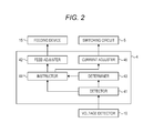
- FIG. 2 is a block diagram illustrating the configuration of the welding controller 4.
- the welding controller 4 has a detector 41, a feed adjuster 42, a determiner 43, an instructor 44, and a current adjuster 45.
- the detector 41 detects whether it is in a short state or an arc state between the welding wire 14 and the work W. Further, when the voltage value detected by the voltage detector 10 is less than or equal to a predetermined value, the detector 41 detects (determines) that it is in the short state between the welding wire 14 and the work W (that is, at this time, the detector 41 detects the short state). On the other hand, when the voltage value detected by the voltage detector 10 is greater than the predetermined value, the detector 41 detects (determines) that it is in the arc state between the welding wire 14 and the work W (that is, at this time, the detector 41 detects the arc state). Further, the detector 41 outputs the detected result to the determiner 43 and the instructor 44.
- the feed adjuster 42 adjusts the feeding state of the welding wire 14 so that the welding wire 14 is forward-fed when the detector 41 detects the arc state and the welding wire 14 is reverse-fed when the detector 41 detects the short state. Further, the feed adjuster 42 controls the feeding device 15 to apply the forward feed and the reverse feed of the welding wire 14 based on the instruction from the instructor 44.
- the determiner 43 determines whether or not a predetermined period has elapsed after the detector 41 has detected the short state. It is noted that the determiner 43 has a timer. Upon receiving the notification from the detector 41 indicating that the short state has been detected, the determiner 43 starts timing. Further, when a predetermined period has elapsed after starting the timing, the determiner 43 notifies it to the instructor 44.
- the instructor 44 instructs the feed adjuster 42 to adjust the feeding state of the welding wire 14 based on the detected result of the detector 41. Specifically, when the detector 41 detects the arc state, the instructor 44 instructs the feed adjuster 42 to forward-feed the welding wire 14. When the detector 41 detects the short state, the instructor 44 instructs the feed adjuster 42 to reverse-feed the welding wire 14.
- the instructor 44 instructs the feed adjuster 42 to continue the reverse feed even when the detector 41 has detected the arc state.
- the instructor 44 instructs the feed adjuster 42 to continue the reverse feed until the detector 41 detects the arc state.
- the instructor 44 notifies the current adjuster 45 of the welding state and the feeding state. Specifically, the instructor 44 notifies the current adjuster 45 of whether the reverse feed is being applied under the short state, the forward feed is being applied under the arc state, or the reverse feed is being applied in spite of the arc state.
- the current adjuster 45 adjusts the current value to be supplied to the welding wire 14 according to the notification from the instructor 44. Specifically, the current adjuster 45 generates the current adjustment signal according to the notification from the instructor 44 and the control pattern of the welding current. Further, the current adjuster 45 outputs the current adjustment signal to the switching circuit 5.
- the current adjuster 45 adjusts the switching circuit 5 so that the current value supplied to the welding wire 14 is set smaller than the maximum value of the current that is supplied to the welding wire 14 in the case of the arc state.
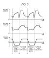
- FIG. 3 illustrates graphs representing temporal changes of the welding current, the welding voltage, and the feeding speed of the welding wire 14 according to the present embodiment.
- the vertical axes of the graphs represent the welding current, the welding voltage, and the feeding speed, respectively.
- the horizontal axes of the graphs all represent time.
- the graph (the waveform) of the feeding speed has a form of trapezoidal waves as illustrated in FIG. 3 .
- the waveform of the feeding speed may be a form of sinusoidal waves, a form of square waves, or a form of triangular waves.
- the short state is detected by the arc welding apparatus 1 (the detector 41) at time T1 indicated in FIG. 3 .
- the arc welding apparatus 1 controls the feeding device 15 so as to change the feeding state of the welding wire 14 from the forward feed to the reverse feed. Further, the arc welding apparatus 1 (the current adjuster 45, the switching circuit 5) gradually increases the welding current.
- the short is then opened and the arc is regenerated, and the welding voltage rises. Then, at the time when the welding voltage exceeds a predetermined value (see, for example, time T2 of FIG. 3 ), the arc welding apparatus 1 detects the arc state. Upon detecting the arc state, the arc welding apparatus 1 controls the feeding device 15 to change the feeding state of the welding wire 14 from the reverse feed to the forward feed.
- the arc welding apparatus 1 supplies the welding current having the maximum current value to the welding wire 14 for a predetermined period. The arc welding apparatus 1 then gradually reduces the welding current.
- the short In response that the welding wire 14 is forward-fed, the short then occurs and the welding voltage decreases. Then, at the time when that welding voltage falls below the predetermined value (see, for example, time T3 of FIG. 3 ), the arc welding apparatus 1 detects the short state. Since the operation of the arc welding apparatus 1 after the detection of such the short state is similar to the operation on and after the time T1, the description thereof will be omitted.
- the arc welding apparatus 1 detects the short state and the arc state, and adjusts the forward feed and the reverse feed of the welding wire 14 based on the detected result.
- the short state and the arc state typically occur at a period close to constant. Therefore, the switching between the forward feed and the reverse feed of the welding wire 14 is done at a predetermined period. As a result, the distance between the tip end of the welding wire 14 and the work W (hereafter, referred to as "arc length") is maintained to a proper length. The arc length is maintained to a proper length, so that the arc welding apparatus 1 is able to reduce the spatter to improve the welding quality.
- the period of the occurrence of the arc state and the short state significantly changes due to the disturbance such as the change in the state of the melting pool or the environment.
- the period of the short state is reduced, if the reverse feed were applied during the short state only as usual, the reverse feed period would also be reduced.
- the welding wire 14 would be insufficiently reverse-fed resulting in the reduced arc length. If the operation entered the arc state with the arc length being reduced, the spatter would increase and thus the poor welding quality would be caused.
- the arc welding apparatus 1 according to the present embodiment is configured to be able to improve the welding quality even when the short state (the short-state period) is reduced while typically applying the forward feed and the reverse feed depending on the arc state and the short state. Specifically, the arc welding apparatus 1 according to the present embodiment continues the reverse feed for a predetermined period even when the arc state is detected. This allows the proper arc length to be maintained, so that the welding quality can be improved. This point will be described in detail by using FIG. 4 .
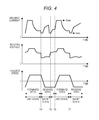
- FIG. 4 illustrates graphs representing temporal changes of the welding current, the welding voltage, and the feeding speed of the welding wire 14 according to the present embodiment.
- the vertical axes of the graphs represent the welding current, the welding voltage, and the feeding speed, respectively.
- the horizontal axes of the graphs all represent time.
- the short state is detected by the arc welding apparatus 1 (the detector 41) at time T4 indicated in FIG. 4 .
- the arc welding apparatus 1 controls the feeding device 15 so as to change the feeding state of the welding wire 14 from the forward feed to the reverse feed.
- the arc welding apparatus 1 continues the reverse feed of the welding wire 14 for a predetermined period. Specifically, even when detecting the arc state at the time T5, the arc welding apparatus 1 reverse-feeds the welding wire 14 until time T6 at which the predetermined period has elapsed from the detection of the short state.
- the arc welding apparatus 1 determines that the predetermined period has elapsed from the detection of the short state. Then, the arc welding apparatus 1 (the instructor 44 and the feed adjuster 42) controls the feeding device 15 to change the feeding state of the welding wire 14 from the reverse feed to the forward feed.
- the arc welding apparatus 1 reduces the value of the welding current supplied to the welding wire 14 to be smaller than the maximum value Imax of the welding current supplied to the welding wire 14 in the case of the arc state. This allows for the suppression of vibration in the melting pool and thus allows for the stable welding.
- the value of the welding current during the reverse feed being applied under the arc state (between the time T5 and the time T6) is set to a constant value between the maximum value Imax and the minimum value Imin of the welding current.
- This value of the welding current is not limited to it, but may be set to substantially the same as the minimum value Imin of the welding current, or may be set so as to increase at a constant increasing rate, for example.
- this predetermined period is set to be substantially the same as the reverse feed period in the case where the short state and the arc state occur at a period close to constant.
- the predetermined period is set to substantially the same as the period from the time T1 to the time T2 of FIG. 3 .
- the setting method of the predetermined period may include, for example, the method of deriving the proper value in advance by the experiment and the like.
- the determiner 43 may change the predetermined period depending on the welding current value inputted from the external controller 16. This is because the period at which the short state and the arc state occur changes when the welding current value is changed. Therefore, the predetermined period is changed depending on the welding current value, so that the predetermined period can be the proper value regardless of the welding current value. This allows for the improvement of the welding quality regardless of the welding current value.
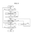
- FIG. 5 is a flowchart illustrating the welding process according to the present embodiment.
- the detector 41 detects whether or not it is in the short state between the welding wire 14 and the work W (step S101).
- the feed adjuster 42 adjusts the feeding state of the welding wire 14 to reverse-feed the welding wire 14 (step S102).
- step S105 is performed (that is, the welding wire 14 is forward-fed).
- the detector 41 detects whether or not it is in the arc state between the welding wire 14 and the work W (step S103). Here, if the detector 41 detects the arc state (step S103, Yes), step S104 is performed. If the detector 41 does not detect the arc state (step S103, No), the process returns to the step S102.
- the determiner 43 determines whether or not a predetermined period has elapsed.
- the feed adjuster 42 adjusts the feeding state of the welding wire 14 to forward-feed the welding wire 14 (step S105).
- step S104 determines that the predetermined period has not elapsed (step S104, No)
- the instructor 44 instructs the feed adjuster 42 to continue the reverse feed (step S106), and the process returns to the step S104.
- the current adjuster 45 reduces the value of the welding current supplied to the welding wire 14 to be smaller than the maximum value Imax of the welding current supplied to the welding wire 14 in the case of the arc state.
- the welding controller 4 determines whether or not to finish the welding (step S107). Here, if it is determined to finish the welding (step S107, Yes), the arc welding apparatus 1 finishes the welding of the work W. On the other hand, if it is not determined to finish the welding (step S107, No), the process returns to the step S101 and the welding is continued.
- the welding controller 4 may determine whether or not to finish the welding based on the time from the start of the welding or the instruction from the external controller 16, for example. It is noted that, in the welding process of FIG. 5 , whether or not to finish the welding is determined when the forward feed is being applied. However, whether or not to finish the welding may be determined when the reverse feed is being applied. Alternatively, the welding controller 4 may accept the welding completion instruction as an interrupt instruction while executing the welding process.
- the detector 41 may compare the welding voltage with a predetermined value. In this case, the detector 41 may detect (determine) that it is in the short state between the welding wire 14 and the work W if the welding voltage is less than or equal to the predetermined value, or may detect (determine) that it is in the arc state between the welding wire 14 and the work W if the welding voltage is greater than the predetermined value. In this way, the process of the step S101 and the process of the step S103 may be performed together in one step.
- the arc welding apparatus has the detector, the feed adjuster, the determiner, and the instructor.
- the detector detects whether it is in the short state or the arc state between the consumable electrode (the welding wire 14) and the welded article (the work W).
- the feed adjuster adjusts the feeding state of the consumable electrode so as to apply the forward feed for feeding the consumable electrode in the direction to the welded article when the detector detects the arc state and apply the reverse feed for feeding the consumable electrode in the direction opposite to the welded article when the detector detects the short state.
- the determiner determines whether or not a predetermined period has elapsed after the detector has detected the short state. Until the determiner determines that the predetermined period has elapsed after the detector has detected the short state, the instructor instructs the feed adjuster to continue the reverse feed even when the detector detects the arc state.
- the reverse feed is continued until at least a predetermined period has elapsed regardless of whether it is in the short state or the arc state between the consumable electrode and the welded article. Therefore, even when the short state is reduced, the spatter can be reduced and thus the welding quality can be improved. That is, the welding quality can be further improved.
- an arc welding system 100 will be described.
- the arc welding apparatus 1 according to the first embodiment and a robot 20 having the welding torch 13 attached to its tip end are combined. This allows for further improvement of the welding quality in the arc welding system 100.
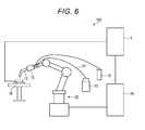
- FIG. 6 is a diagram illustrating the arc welding system 100 according to the second embodiment. It is noted that, in the second embodiment, the same components as those in the first embodiment are provided with the same reference numerals and the description thereof will be omitted.
- the arc welding system 100 has the arc welding apparatus 1 according to the first embodiment and the robot 20.
- the robot 20 moves the tip end of the welding wire 14 relatively with respect to the work W.
- the arc welding system 100 further has the welding torch 13, the welding wire 14, the feeding device 15, the external controller 16, a gas cylinder 18, and a welding wire supplier 19.
- the external controller 16 functions also as a controller of the robot 20. That is, the external controller 16 controls the robot 20 and changes the position and attitude of the welding torch 13. For example, the external controller 16 moves the welding torch 13 so that the tip end of the welding torch 13 traces a desired welding line with respect to the work W.
- the welding wire supplier 19 supplies the incorporated welding wire 14 to the feeding device 15.
- the gas cylinder 18 supplies a shield gas to the welding torch 13.
- the arc welding apparatus 1 according to the first embodiment is mounted to the arc welding system 100. This allows for further improvement of the welding quality in the arc welding system 100.
- the welding wire 14 is an example of the consumable electrode.
- the work W is an example of the welded article.
- the detector 41 is an example of the detection unit.
- the feed adjuster 42 is an example of the feed adjustment unit.
- the determiner 43 is an example of the determination unit.
- the instructor 44 is an example of the instruction unit.
- the current adjuster 45 is an example of the current adjustment unit.
- the arc welding apparatus has: a detector configured to detect whether it is in a short state or an arc state between a consumable electrode and a welded article; a feed adjuster configured to adjust a feeding state of the consumable electrode so as to apply a forward feed for feeding the consumable electrode in a direction to the welded article when the detector detects the arc state and apply a reverse feed for feeding the consumable electrode in a direction opposite to the welded article when the detector detects the short state; a determiner configured to determine whether or not a predetermined period has elapsed after the detector has detected the short state; and an instructor configured to instruct the feed adjuster to continue the reverse feed even when the detector detects the arc state, until the determiner determines that the predetermined period has elapsed after the detector has detected the short
- the instructor instructs the feed adjuster to continue the reverse feed until the detector detects the arc state.
- the third arc welding apparatus has a current adjuster configured to reduce a current value supplied to the consumable electrode to be smaller than the maximum value of a current supplied to the consumable electrode in a case of the arc state until the determiner determines that the predetermined period has elapsed after the detector has detected the arc state.
- the determiner changes the predetermined period depending on a welding current.
- the first arc welding method includes: a detection step for detecting whether it is in a short state or an arc state between a consumable electrode and a welded article; a feed adjustment step for adjusting a feeding state of the consumable electrode so as to apply a forward feed for feeding the consumable electrode in a direction to the welded article when the detection step detects the arc state and apply a reverse feed for feeding the consumable electrode in a direction opposite to the welded article when the detection step detects the short state; a determination step for determining whether or not a predetermined period has elapsed after the detection step has detected the short state; and an instruction step for instructing the feed adjustment step to continue the reverse feed even when the detection step detects the arc state, until the determination step determines that the predetermined period has elapsed after the detection step has detected the short state.
- the instruction step instructs the feed adjustment step to continue the reverse feed until the detection step detects the arc state.
- the third arc welding method includes a current adjustment step for reducing a current value supplied to the consumable electrode to be smaller than the maximum value of a current supplied to the consumable electrode in a case of the arc state until the determination step determines that the predetermined period has elapsed after the detection step has detected the arc state.
- the first arc welding system has: an arc welding apparatus having a detector configured to detect whether it is in a short state or an arc state between a consumable electrode and a welded article, a feed adjuster configured to adjust a feeding state of the consumable electrode so as to apply a forward feed for feeding the consumable electrode in a direction to the welded article when the detector detects the arc state and apply a reverse feed for feeding the consumable electrode in a direction opposite to the welded article when the detector detects the short state, a determiner configured to determine whether or not a predetermined period has elapsed after the detector has detected the short state, and an instructor configured to instruct the feed adjuster to continue the reverse feed even when the detector detects the arc state, until the determiner determines that the predetermined period has elapsed after the detector has detected the short state; and a robot configured to move a tip end of the consumable electrode with respect to the welded article.
- the first welded article is welded by an arc welding method including a detection step for detecting whether it is in a short state or an arc state between a consumable electrode and a welded article, a feed adjustment step for adjusting a feeding state of the consumable electrode so as to apply a forward feed for feeding the consumable electrode in a direction to the welded article when the detection step detects the arc state and apply a reverse feed for feeding the consumable electrode in a direction opposite to the welded article when the detection step detects the short state, a determination step for determining whether or not a predetermined period has elapsed after the detection step has detected the short state, and an instruction step for instructing the feed adjustment step to continue the reverse feed even when the detection step detects the arc state, until the determination step determines that the predetermined period has elapsed after the detection step has detected the short state.
Landscapes
- Engineering & Computer Science (AREA)
- Physics & Mathematics (AREA)
- Plasma & Fusion (AREA)
- Mechanical Engineering (AREA)
- Arc Welding Control (AREA)
Applications Claiming Priority (1)
| Application Number | Priority Date | Filing Date | Title |
|---|---|---|---|
| JP2013194109A JP6007879B2 (ja) | 2013-09-19 | 2013-09-19 | アーク溶接装置、アーク溶接方法、及びアーク溶接システム |
Publications (3)
| Publication Number | Publication Date |
|---|---|
| EP2865476A2 true EP2865476A2 (de) | 2015-04-29 |
| EP2865476A3 EP2865476A3 (de) | 2015-10-21 |
| EP2865476B1 EP2865476B1 (de) | 2018-06-20 |
Family
ID=51564467
Family Applications (1)
| Application Number | Title | Priority Date | Filing Date |
|---|---|---|---|
| EP14184394.6A Active EP2865476B1 (de) | 2013-09-19 | 2014-09-11 | Lichtbogenschweißvorrichtung, Lichtbogenschweißverfahren und geschweißter Gegenstand |
Country Status (4)
| Country | Link |
|---|---|
| US (1) | US9770777B2 (de) |
| EP (1) | EP2865476B1 (de) |
| JP (1) | JP6007879B2 (de) |
| CN (1) | CN104439613B (de) |
Families Citing this family (4)
| Publication number | Priority date | Publication date | Assignee | Title |
|---|---|---|---|---|
| WO2011064952A1 (ja) * | 2009-11-25 | 2011-06-03 | パナソニック株式会社 | 溶接方法および溶接装置 |
| JP6601870B2 (ja) * | 2015-09-28 | 2019-11-06 | 株式会社ダイヘン | 正逆送給交流アーク溶接方法 |
| JP6800865B2 (ja) | 2015-09-30 | 2020-12-16 | 株式会社ダイヘン | アーク溶接装置およびアーク溶接方法 |
| US11161191B2 (en) * | 2016-07-19 | 2021-11-02 | Siemens Energy, Inc. | Process and apparatus for welding workpiece having heat sensitive material |
Citations (1)
| Publication number | Priority date | Publication date | Assignee | Title |
|---|---|---|---|---|
| JP4807474B2 (ja) | 2009-06-19 | 2011-11-02 | パナソニック株式会社 | 消耗電極式アーク溶接方法および消耗電極式アーク溶接装置 |
Family Cites Families (9)
| Publication number | Priority date | Publication date | Assignee | Title |
|---|---|---|---|---|
| AT409832B (de) * | 1999-04-26 | 2002-11-25 | Fronius Schweissmasch Prod | Schweissverfahren und schweissgerät zur durchführung des schweissverfahrens |
| AUPS274002A0 (en) * | 2002-06-03 | 2002-06-20 | University Of Wollongong, The | Control method and system for metal arc welding |
| AU2007231786B2 (en) * | 2003-12-05 | 2010-02-25 | Illinois Tool Works Inc. | Method and apparatus for feeding wire to a welding arc |
| US7960672B2 (en) * | 2004-06-08 | 2011-06-14 | Kabushiki Yaskawa Denki | Robot welding controller and control method |
| AT501995B1 (de) | 2005-05-24 | 2009-07-15 | Fronius Int Gmbh | Kalt-metall-transfer-schweissverfahren sowie schweissanlage |
| CN102341207B (zh) * | 2009-08-28 | 2013-10-09 | 松下电器产业株式会社 | 电弧焊接方法及电弧焊接装置 |
| CN102441722B (zh) * | 2010-09-30 | 2015-05-27 | 株式会社大亨 | 电弧焊接方法 |
| JP5026603B2 (ja) * | 2010-09-30 | 2012-09-12 | 株式会社ダイヘン | アーク溶接方法 |
| EP2732901B1 (de) * | 2011-07-12 | 2018-08-08 | Panasonic Intellectual Property Management Co., Ltd. | Verfahren zur steuerung einer lichtbogenschweissung und lichtbogenschweissvorrichtung |
-
2013
- 2013-09-19 JP JP2013194109A patent/JP6007879B2/ja active Active
-
2014
- 2014-08-01 CN CN201410377314.3A patent/CN104439613B/zh active Active
- 2014-09-11 EP EP14184394.6A patent/EP2865476B1/de active Active
- 2014-09-18 US US14/489,491 patent/US9770777B2/en active Active
Patent Citations (1)
| Publication number | Priority date | Publication date | Assignee | Title |
|---|---|---|---|---|
| JP4807474B2 (ja) | 2009-06-19 | 2011-11-02 | パナソニック株式会社 | 消耗電極式アーク溶接方法および消耗電極式アーク溶接装置 |
Also Published As
| Publication number | Publication date |
|---|---|
| CN104439613B (zh) | 2017-01-11 |
| JP6007879B2 (ja) | 2016-10-12 |
| US20150076132A1 (en) | 2015-03-19 |
| US9770777B2 (en) | 2017-09-26 |
| EP2865476B1 (de) | 2018-06-20 |
| JP2015058454A (ja) | 2015-03-30 |
| CN104439613A (zh) | 2015-03-25 |
| EP2865476A3 (de) | 2015-10-21 |
Similar Documents
| Publication | Publication Date | Title |
|---|---|---|
| EP2716395B1 (de) | Verfahren zur steuerung einer lichtbogenschweissung und lichtbogenschweissvorrichtung | |
| JP3203250U (ja) | 単一の溶接モードを有する電源を用いた溶接の方法及びシステム | |
| EP2810730B1 (de) | Lichtbogenschweißvorrichtung, Lichtbogenschweißsystem und Lichtbogenschweißverfahren | |
| EP2865476B1 (de) | Lichtbogenschweißvorrichtung, Lichtbogenschweißverfahren und geschweißter Gegenstand | |
| EP2810732B2 (de) | Lichtbogenschweißvorrichtung, Lichtbogenschweißsystem und Lichtbogenschweißverfahren | |
| KR20180113459A (ko) | 아크 용접 및 와이어 조작 제어를 위한 시스템 및 방법 | |
| JP5943460B2 (ja) | 消耗電極アーク溶接のアークスタート制御方法 | |
| US20140360997A1 (en) | Arc welding apparatus, arc welding system, and arc welding method | |
| JP7554613B2 (ja) | 溶接電源システム | |
| JP2004268095A (ja) | アーク溶接機の制御方法 | |
| JP7497259B2 (ja) | 溶接電源システム | |
| US10537953B2 (en) | Arc welding control method and arc welding apparatus | |
| JP2011200918A (ja) | 交流非消耗電極アーク溶接制御方法 | |
| JP2009045662A (ja) | 溶接電源 | |
| JP2016147267A (ja) | アーク溶接制御方法 | |
| JP2020138207A (ja) | パルスアーク溶接の出力制御方法 | |
| JP2000271741A (ja) | アーク電流制御方法及び溶接装置 | |
| JP2021010934A (ja) | ティグ溶接の溶接終了方法 | |
| JP2021020232A (ja) | 被覆アーク溶接制御方法 |
Legal Events
| Date | Code | Title | Description |
|---|---|---|---|
| PUAI | Public reference made under article 153(3) epc to a published international application that has entered the european phase |
Free format text: ORIGINAL CODE: 0009012 |
|
| 17P | Request for examination filed |
Effective date: 20140911 |
|
| AK | Designated contracting states |
Kind code of ref document: A2 Designated state(s): AL AT BE BG CH CY CZ DE DK EE ES FI FR GB GR HR HU IE IS IT LI LT LU LV MC MK MT NL NO PL PT RO RS SE SI SK SM TR |
|
| AX | Request for extension of the european patent |
Extension state: BA ME |
|
| PUAL | Search report despatched |
Free format text: ORIGINAL CODE: 0009013 |
|
| AK | Designated contracting states |
Kind code of ref document: A3 Designated state(s): AL AT BE BG CH CY CZ DE DK EE ES FI FR GB GR HR HU IE IS IT LI LT LU LV MC MK MT NL NO PL PT RO RS SE SI SK SM TR |
|
| AX | Request for extension of the european patent |
Extension state: BA ME |
|
| RIC1 | Information provided on ipc code assigned before grant |
Ipc: B23K 9/173 20060101ALI20150914BHEP Ipc: B23K 9/09 20060101AFI20150914BHEP Ipc: B23K 9/12 20060101ALI20150914BHEP Ipc: B23K 9/095 20060101ALI20150914BHEP |
|
| R17P | Request for examination filed (corrected) |
Effective date: 20151110 |
|
| RBV | Designated contracting states (corrected) |
Designated state(s): AL AT BE BG CH CY CZ DE DK EE ES FI FR GB GR HR HU IE IS IT LI LT LU LV MC MK MT NL NO PL PT RO RS SE SI SK SM TR |
|
| GRAP | Despatch of communication of intention to grant a patent |
Free format text: ORIGINAL CODE: EPIDOSNIGR1 |
|
| INTG | Intention to grant announced |
Effective date: 20180123 |
|
| GRAS | Grant fee paid |
Free format text: ORIGINAL CODE: EPIDOSNIGR3 |
|
| GRAA | (expected) grant |
Free format text: ORIGINAL CODE: 0009210 |
|
| AK | Designated contracting states |
Kind code of ref document: B1 Designated state(s): AL AT BE BG CH CY CZ DE DK EE ES FI FR GB GR HR HU IE IS IT LI LT LU LV MC MK MT NL NO PL PT RO RS SE SI SK SM TR |
|
| REG | Reference to a national code |
Ref country code: GB Ref legal event code: FG4D |
|
| REG | Reference to a national code |
Ref country code: IE Ref legal event code: FG4D |
|
| REG | Reference to a national code |
Ref country code: AT Ref legal event code: REF Ref document number: 1010226 Country of ref document: AT Kind code of ref document: T Effective date: 20180715 |
|
| REG | Reference to a national code |
Ref country code: DE Ref legal event code: R096 Ref document number: 602014027242 Country of ref document: DE |
|
| REG | Reference to a national code |
Ref country code: NL Ref legal event code: MP Effective date: 20180620 |
|
| PG25 | Lapsed in a contracting state [announced via postgrant information from national office to epo] |
Ref country code: BG Free format text: LAPSE BECAUSE OF FAILURE TO SUBMIT A TRANSLATION OF THE DESCRIPTION OR TO PAY THE FEE WITHIN THE PRESCRIBED TIME-LIMIT Effective date: 20180920 Ref country code: FI Free format text: LAPSE BECAUSE OF FAILURE TO SUBMIT A TRANSLATION OF THE DESCRIPTION OR TO PAY THE FEE WITHIN THE PRESCRIBED TIME-LIMIT Effective date: 20180620 Ref country code: SE Free format text: LAPSE BECAUSE OF FAILURE TO SUBMIT A TRANSLATION OF THE DESCRIPTION OR TO PAY THE FEE WITHIN THE PRESCRIBED TIME-LIMIT Effective date: 20180620 Ref country code: NO Free format text: LAPSE BECAUSE OF FAILURE TO SUBMIT A TRANSLATION OF THE DESCRIPTION OR TO PAY THE FEE WITHIN THE PRESCRIBED TIME-LIMIT Effective date: 20180920 Ref country code: LT Free format text: LAPSE BECAUSE OF FAILURE TO SUBMIT A TRANSLATION OF THE DESCRIPTION OR TO PAY THE FEE WITHIN THE PRESCRIBED TIME-LIMIT Effective date: 20180620 |
|
| REG | Reference to a national code |
Ref country code: LT Ref legal event code: MG4D |
|
| PG25 | Lapsed in a contracting state [announced via postgrant information from national office to epo] |
Ref country code: RS Free format text: LAPSE BECAUSE OF FAILURE TO SUBMIT A TRANSLATION OF THE DESCRIPTION OR TO PAY THE FEE WITHIN THE PRESCRIBED TIME-LIMIT Effective date: 20180620 Ref country code: HR Free format text: LAPSE BECAUSE OF FAILURE TO SUBMIT A TRANSLATION OF THE DESCRIPTION OR TO PAY THE FEE WITHIN THE PRESCRIBED TIME-LIMIT Effective date: 20180620 Ref country code: GR Free format text: LAPSE BECAUSE OF FAILURE TO SUBMIT A TRANSLATION OF THE DESCRIPTION OR TO PAY THE FEE WITHIN THE PRESCRIBED TIME-LIMIT Effective date: 20180921 Ref country code: LV Free format text: LAPSE BECAUSE OF FAILURE TO SUBMIT A TRANSLATION OF THE DESCRIPTION OR TO PAY THE FEE WITHIN THE PRESCRIBED TIME-LIMIT Effective date: 20180620 |
|
| REG | Reference to a national code |
Ref country code: AT Ref legal event code: MK05 Ref document number: 1010226 Country of ref document: AT Kind code of ref document: T Effective date: 20180620 |
|
| PG25 | Lapsed in a contracting state [announced via postgrant information from national office to epo] |
Ref country code: NL Free format text: LAPSE BECAUSE OF FAILURE TO SUBMIT A TRANSLATION OF THE DESCRIPTION OR TO PAY THE FEE WITHIN THE PRESCRIBED TIME-LIMIT Effective date: 20180620 |
|
| PG25 | Lapsed in a contracting state [announced via postgrant information from national office to epo] |
Ref country code: RO Free format text: LAPSE BECAUSE OF FAILURE TO SUBMIT A TRANSLATION OF THE DESCRIPTION OR TO PAY THE FEE WITHIN THE PRESCRIBED TIME-LIMIT Effective date: 20180620 Ref country code: SK Free format text: LAPSE BECAUSE OF FAILURE TO SUBMIT A TRANSLATION OF THE DESCRIPTION OR TO PAY THE FEE WITHIN THE PRESCRIBED TIME-LIMIT Effective date: 20180620 Ref country code: CZ Free format text: LAPSE BECAUSE OF FAILURE TO SUBMIT A TRANSLATION OF THE DESCRIPTION OR TO PAY THE FEE WITHIN THE PRESCRIBED TIME-LIMIT Effective date: 20180620 Ref country code: EE Free format text: LAPSE BECAUSE OF FAILURE TO SUBMIT A TRANSLATION OF THE DESCRIPTION OR TO PAY THE FEE WITHIN THE PRESCRIBED TIME-LIMIT Effective date: 20180620 Ref country code: AT Free format text: LAPSE BECAUSE OF FAILURE TO SUBMIT A TRANSLATION OF THE DESCRIPTION OR TO PAY THE FEE WITHIN THE PRESCRIBED TIME-LIMIT Effective date: 20180620 Ref country code: IS Free format text: LAPSE BECAUSE OF FAILURE TO SUBMIT A TRANSLATION OF THE DESCRIPTION OR TO PAY THE FEE WITHIN THE PRESCRIBED TIME-LIMIT Effective date: 20181020 Ref country code: PL Free format text: LAPSE BECAUSE OF FAILURE TO SUBMIT A TRANSLATION OF THE DESCRIPTION OR TO PAY THE FEE WITHIN THE PRESCRIBED TIME-LIMIT Effective date: 20180620 |
|
| PG25 | Lapsed in a contracting state [announced via postgrant information from national office to epo] |
Ref country code: SM Free format text: LAPSE BECAUSE OF FAILURE TO SUBMIT A TRANSLATION OF THE DESCRIPTION OR TO PAY THE FEE WITHIN THE PRESCRIBED TIME-LIMIT Effective date: 20180620 Ref country code: IT Free format text: LAPSE BECAUSE OF FAILURE TO SUBMIT A TRANSLATION OF THE DESCRIPTION OR TO PAY THE FEE WITHIN THE PRESCRIBED TIME-LIMIT Effective date: 20180620 Ref country code: ES Free format text: LAPSE BECAUSE OF FAILURE TO SUBMIT A TRANSLATION OF THE DESCRIPTION OR TO PAY THE FEE WITHIN THE PRESCRIBED TIME-LIMIT Effective date: 20180620 |
|
| REG | Reference to a national code |
Ref country code: DE Ref legal event code: R097 Ref document number: 602014027242 Country of ref document: DE |
|
| PLBE | No opposition filed within time limit |
Free format text: ORIGINAL CODE: 0009261 |
|
| STAA | Information on the status of an ep patent application or granted ep patent |
Free format text: STATUS: NO OPPOSITION FILED WITHIN TIME LIMIT |
|
| PG25 | Lapsed in a contracting state [announced via postgrant information from national office to epo] |
Ref country code: MC Free format text: LAPSE BECAUSE OF FAILURE TO SUBMIT A TRANSLATION OF THE DESCRIPTION OR TO PAY THE FEE WITHIN THE PRESCRIBED TIME-LIMIT Effective date: 20180620 |
|
| REG | Reference to a national code |
Ref country code: CH Ref legal event code: PL |
|
| GBPC | Gb: european patent ceased through non-payment of renewal fee |
Effective date: 20180920 |
|
| 26N | No opposition filed |
Effective date: 20190321 |
|
| PG25 | Lapsed in a contracting state [announced via postgrant information from national office to epo] |
Ref country code: DK Free format text: LAPSE BECAUSE OF FAILURE TO SUBMIT A TRANSLATION OF THE DESCRIPTION OR TO PAY THE FEE WITHIN THE PRESCRIBED TIME-LIMIT Effective date: 20180620 |
|
| REG | Reference to a national code |
Ref country code: BE Ref legal event code: MM Effective date: 20180930 |
|
| REG | Reference to a national code |
Ref country code: IE Ref legal event code: MM4A |
|
| PG25 | Lapsed in a contracting state [announced via postgrant information from national office to epo] |
Ref country code: LU Free format text: LAPSE BECAUSE OF NON-PAYMENT OF DUE FEES Effective date: 20180911 |
|
| PG25 | Lapsed in a contracting state [announced via postgrant information from national office to epo] |
Ref country code: IE Free format text: LAPSE BECAUSE OF NON-PAYMENT OF DUE FEES Effective date: 20180911 |
|
| PG25 | Lapsed in a contracting state [announced via postgrant information from national office to epo] |
Ref country code: CH Free format text: LAPSE BECAUSE OF NON-PAYMENT OF DUE FEES Effective date: 20180930 Ref country code: LI Free format text: LAPSE BECAUSE OF NON-PAYMENT OF DUE FEES Effective date: 20180930 Ref country code: FR Free format text: LAPSE BECAUSE OF NON-PAYMENT OF DUE FEES Effective date: 20180930 Ref country code: BE Free format text: LAPSE BECAUSE OF NON-PAYMENT OF DUE FEES Effective date: 20180930 Ref country code: SI Free format text: LAPSE BECAUSE OF FAILURE TO SUBMIT A TRANSLATION OF THE DESCRIPTION OR TO PAY THE FEE WITHIN THE PRESCRIBED TIME-LIMIT Effective date: 20180620 |
|
| PG25 | Lapsed in a contracting state [announced via postgrant information from national office to epo] |
Ref country code: GB Free format text: LAPSE BECAUSE OF NON-PAYMENT OF DUE FEES Effective date: 20180920 |
|
| PG25 | Lapsed in a contracting state [announced via postgrant information from national office to epo] |
Ref country code: AL Free format text: LAPSE BECAUSE OF FAILURE TO SUBMIT A TRANSLATION OF THE DESCRIPTION OR TO PAY THE FEE WITHIN THE PRESCRIBED TIME-LIMIT Effective date: 20180620 |
|
| PG25 | Lapsed in a contracting state [announced via postgrant information from national office to epo] |
Ref country code: MT Free format text: LAPSE BECAUSE OF NON-PAYMENT OF DUE FEES Effective date: 20180911 |
|
| PG25 | Lapsed in a contracting state [announced via postgrant information from national office to epo] |
Ref country code: TR Free format text: LAPSE BECAUSE OF FAILURE TO SUBMIT A TRANSLATION OF THE DESCRIPTION OR TO PAY THE FEE WITHIN THE PRESCRIBED TIME-LIMIT Effective date: 20180620 |
|
| PG25 | Lapsed in a contracting state [announced via postgrant information from national office to epo] |
Ref country code: HU Free format text: LAPSE BECAUSE OF FAILURE TO SUBMIT A TRANSLATION OF THE DESCRIPTION OR TO PAY THE FEE WITHIN THE PRESCRIBED TIME-LIMIT; INVALID AB INITIO Effective date: 20140911 Ref country code: PT Free format text: LAPSE BECAUSE OF FAILURE TO SUBMIT A TRANSLATION OF THE DESCRIPTION OR TO PAY THE FEE WITHIN THE PRESCRIBED TIME-LIMIT Effective date: 20180620 |
|
| PG25 | Lapsed in a contracting state [announced via postgrant information from national office to epo] |
Ref country code: CY Free format text: LAPSE BECAUSE OF FAILURE TO SUBMIT A TRANSLATION OF THE DESCRIPTION OR TO PAY THE FEE WITHIN THE PRESCRIBED TIME-LIMIT Effective date: 20180620 Ref country code: MK Free format text: LAPSE BECAUSE OF NON-PAYMENT OF DUE FEES Effective date: 20180620 |
|
| PGFP | Annual fee paid to national office [announced via postgrant information from national office to epo] |
Ref country code: DE Payment date: 20250730 Year of fee payment: 12 |