EP2864566B2 - Porte coulissante anti-effraction - Google Patents
Porte coulissante anti-effraction Download PDFInfo
- Publication number
- EP2864566B2 EP2864566B2 EP13727601.0A EP13727601A EP2864566B2 EP 2864566 B2 EP2864566 B2 EP 2864566B2 EP 13727601 A EP13727601 A EP 13727601A EP 2864566 B2 EP2864566 B2 EP 2864566B2
- Authority
- EP
- European Patent Office
- Prior art keywords
- closing
- vertical
- millimeters
- groove
- sliding wing
- Prior art date
- Legal status (The legal status is an assumption and is not a legal conclusion. Google has not performed a legal analysis and makes no representation as to the accuracy of the status listed.)
- Active
Links
Images


Classifications
-
- E—FIXED CONSTRUCTIONS
- E06—DOORS, WINDOWS, SHUTTERS, OR ROLLER BLINDS IN GENERAL; LADDERS
- E06B—FIXED OR MOVABLE CLOSURES FOR OPENINGS IN BUILDINGS, VEHICLES, FENCES OR LIKE ENCLOSURES IN GENERAL, e.g. DOORS, WINDOWS, BLINDS, GATES
- E06B5/00—Doors, windows, or like closures for special purposes; Border constructions therefor
- E06B5/10—Doors, windows, or like closures for special purposes; Border constructions therefor for protection against air-raid or other war-like action; for other protective purposes
- E06B5/11—Doors, windows, or like closures for special purposes; Border constructions therefor for protection against air-raid or other war-like action; for other protective purposes against burglary
- E06B5/113—Arrangements at the edges of the wings, e.g. with door guards to prevent the insertion of prying tools
-
- E—FIXED CONSTRUCTIONS
- E05—LOCKS; KEYS; WINDOW OR DOOR FITTINGS; SAFES
- E05B—LOCKS; ACCESSORIES THEREFOR; HANDCUFFS
- E05B65/00—Locks or fastenings for special use
- E05B65/08—Locks or fastenings for special use for sliding wings
-
- E—FIXED CONSTRUCTIONS
- E05—LOCKS; KEYS; WINDOW OR DOOR FITTINGS; SAFES
- E05B—LOCKS; ACCESSORIES THEREFOR; HANDCUFFS
- E05B65/00—Locks or fastenings for special use
- E05B65/08—Locks or fastenings for special use for sliding wings
- E05B65/0811—Locks or fastenings for special use for sliding wings the bolts pivoting about an axis perpendicular to the wings
-
- E—FIXED CONSTRUCTIONS
- E05—LOCKS; KEYS; WINDOW OR DOOR FITTINGS; SAFES
- E05C—BOLTS OR FASTENING DEVICES FOR WINGS, SPECIALLY FOR DOORS OR WINDOWS
- E05C19/00—Other devices specially designed for securing wings, e.g. with suction cups
-
- E—FIXED CONSTRUCTIONS
- E05—LOCKS; KEYS; WINDOW OR DOOR FITTINGS; SAFES
- E05D—HINGES OR SUSPENSION DEVICES FOR DOORS, WINDOWS OR WINGS
- E05D15/00—Suspension arrangements for wings
- E05D15/06—Suspension arrangements for wings for wings sliding horizontally more or less in their own plane
- E05D15/0621—Details, e.g. suspension or supporting guides
-
- E—FIXED CONSTRUCTIONS
- E06—DOORS, WINDOWS, SHUTTERS, OR ROLLER BLINDS IN GENERAL; LADDERS
- E06B—FIXED OR MOVABLE CLOSURES FOR OPENINGS IN BUILDINGS, VEHICLES, FENCES OR LIKE ENCLOSURES IN GENERAL, e.g. DOORS, WINDOWS, BLINDS, GATES
- E06B3/00—Window sashes, door leaves, or like elements for closing wall or like openings; Layout of fixed or moving closures, e.g. windows in wall or like openings; Features of rigidly-mounted outer frames relating to the mounting of wing frames
- E06B3/32—Arrangements of wings characterised by the manner of movement; Arrangements of movable wings in openings; Features of wings or frames relating solely to the manner of movement of the wing
- E06B3/34—Arrangements of wings characterised by the manner of movement; Arrangements of movable wings in openings; Features of wings or frames relating solely to the manner of movement of the wing with only one kind of movement
- E06B3/42—Sliding wings; Details of frames with respect to guiding
- E06B3/46—Horizontally-sliding wings
Definitions
- the present invention relates to a sliding leaf system according to the preamble of claim 1.
- Sliding leaf systems in particular sliding door systems, are widely used, preferably in places where building openings are frequently walked through by people.
- a sliding sash system is able to quickly and reliably operate a large building opening through which one or more people can pass at the same time. It is a fundamental requirement that these sliding sash systems also prevent unauthorized access, i.e. that they can be locked overnight, for example.
- the main closing edge of these systems represents a weak point of the locking system in terms of burglary security.
- the WO 2010 034 081 A1 discloses a lock with a movable along the main closing edge mounted engagement element on a sliding leaf.
- this engagement element can be moved from a release position into a locking position, whereby it can be brought into engagement with a counterpart on the other sliding leaf that protrudes into the movement of the engagement element and can then be determined, with which the sliding door is closed.
- Such a construction is disadvantageous, however, since relatively large openings and/or elements protruding in the closing direction must be provided in the closing edges of the sliding doors for the engagement of the engagement element and counterpart.
- a complex construction must be provided for the actuation of the locking mechanism, which reliably provides the linear movement of the engagement element over several centimeters.
- Sealing elements for sealing the main closing edge in sliding door systems are, for example, from the documents DE 102 12 09 B4 , DE 10 2006 062 332 A1 and EP 1 431 501 B1 known. These sealing elements seal the closing edge, in particular with regard to gas exchange, but do not increase the security of the door system against unauthorized access.
- a sliding leaf system in particular an automatic sliding door system, comprising at least one sliding leaf, the sliding leaf being displaceable in a floor guide device along a closing movement, closing a building opening in a passage direction, and providing a first vertical closing edge in a substantially horizontal closing direction, and the Sliding leaf system provides a second vertical closing edge, wherein the first and the second vertical closing edge can be brought into mutually closing contact, and wherein the sliding leaf provides a horizontal closing edge which, together with the floor guide device, forms a horizontal secondary closing edge extending along the closing direction, thereby solved, that on at least one of these vertical closing edges at least one outer flank, which extends essentially in the vertical direction and protrudes freely in the closing direction, is made of metal or plastic or a combination thereof, is dimensionally stable and is attached to the corresponding vertical closing edge offset towards an outside of the building opening is provided, at least in sections , that in each case opposite this outer flank on the other vertical closing edge there is a dimensionally stable comb which corresponds to
- the outer flank forms a first step or offset with the vertical closing edge to which it is attached, the crest forming a second step or offset with the other vertical closing edge offset forms.
- the first stage and the second stage are of opposite design here, so that they can engage in one another in the closing direction.
- the first and the second stage can also be multi-stage.
- the outer flank overlaps the ridge at least partially, preferably essentially completely, so that the ridge is covered by the outer flank towards the outside of the building opening. A free end of the comb is therefore not accessible from the outside when the vertical closing edges are in closing contact.
- a further development of the sliding sash system is characterized in that on the vertical closing edge providing the outer flank there is a further inner flank which runs essentially parallel to the outer flank and is offset in the passage direction from the outer flank towards the inside of the building opening.
- This inner flank also protrudes towards the ridge, the inner flank being essentially mirror-symmetrical to the outer flank with respect to a mirror plane, this mirror plane being a vertical plane parallel to the building opening through the center of the wing.
- a substantially vertical groove is formed between the outer flank and the inner flank, which is open in the closing direction and is delimited in a direction parallel to the direction of passage through the outer and inner flanks.
- the flanks preferably protrude substantially the same distance in the closing direction over the vertical closing edge.
- the groove formed in this way and said ridge are designed in such a way that they can be brought into mutual engagement by the closing movement. It is preferred that this engagement, taken together in sections, extends over at least one half of the longitudinal extent of the vertical closing edges, preferably over the entire longitudinal extent of the vertical closing edges. It is further preferred that this ridge extends in the passage direction essentially over the clear width of the groove and in the vertical direction essentially over a length of the groove.
- the ridge engages substantially to a depth of the groove.
- the outer flank is supported by the crest and can withstand pressure perpendicular to the flank (from the outside).
- the flank(s) protrudes more than 10 millimeters to 30 millimeters in the closing direction beyond the vertical closing edge and has or have a material thickness in the direction of passage which preferably tapers towards a free end of the flank(s) and in each case at least 2 Millimeters to 10 millimeters, preferably more than 3 millimeters, in particular 4 millimeters or more.
- the comb can then be, for example, 20 to 90 millimeters wide at its free end in the passage direction.
- the flank is to be understood here as a comb-like projection which covers the comb towards the inside (inner flank) or outside (outer flank) of the building opening.
- the vertical closing edges come together and are there, protected by the flank against access from the outside, lockable.
- the tongue and groove system thus massively prevents access to the locking points, e.g. to swing bolts, using burglary tools.
- the ridge is offset against the inside of the building opening and attached to the corresponding vertical closing edge, so that the outer flank, which can be covered over the ridge towards the outside of the building opening, overlaps the ridge in the closing direction against the vertical closing edge providing the ridge to such an extent that a vertical running gap between the free end of the outer flank and the crest providing vertical closing edge has a clear width in the closing direction of less than 2 millimeters, in particular less than essentially 1 millimeter.
- an essentially flush surface is formed towards the outside of the building opening.
- flanks are preferably at least 10 millimeters or more, in particular 20 to 90 millimeters apart from one another in the passage direction and preferably run essentially continuously along the vertical closing edge.
- these flanks are preferably attached to end regions of the corresponding vertical closing edge which are opposite in the passage direction, ie close to the vertical edges of the sliding leaf.
- the groove formed by the inner and outer flanks preferably has a depth of at least 10 millimeters to 30 millimeters or more in a direction parallel to the closing direction, with a clear width in the passage direction being at least 10 millimeters or more, in particular 20 to 90 millimeters.
- a sliding sash system comprising at least one sliding sash, the sliding sash being displaceable in a floor guide device along a closing movement, closing a building opening in a passage direction and providing a first vertical closing edge in a substantially horizontal closing direction, and the sliding sash system providing a second vertical closing edge provides, wherein the first and the second vertical closing edge can be brought into mutually closing contact, and wherein the sliding leaf provides a horizontal closing edge which, together with the floor guide device, forms a horizontal secondary closing edge extending along the closing direction, thereby solved, that on at least one of these vertical closing edges there is at least in sections at least one dimensionally stable groove which extends essentially in the vertical direction and is open in the closing direction and is made of metal or plastic or a combination thereof, and opposite this groove on the other vertical closing edge there is a substantially corresponding groove in the vertical direction and protruding in the closing direction, made of metal or plastic or a combination thereof, dimensionally stable comb is
- the groove is designed as a channel-shaped indentation with a depth of preferably at least essentially 10 millimeters, in particular essentially 11.5 millimeters up to 30 millimeters.
- the comb a projection running along the main closing edge, is functionally designed as a tongue and is suitable for forming a tongue and groove connection with the groove. It is expedient here to let the comb reach down to the depth of the groove (that is to say at its rear boundary), so that sufficient mechanical stability is generated in the closed position. This makes it clear that it is preferable if the crest protrudes in the direction of the groove approximately as far as the groove is deep.
- These corresponding elements are therefore preferably shaped essentially as geometric counterparts.
- dimensionally stable means that the interlocking elements groove and comb remain dimensionally stable in engagement even under the action of force, in particular from the passage direction (and are also correspondingly inherently stable) and counteract this action of force.
- Typical forces would be, for example, when the door is kicked; such a force can be, for example, 100N to 6000N or more.
- the comb and the groove are appropriately dimensioned (see below) so that forces which, for example, during an attempted break-in are directed at a weak point in the locking system, namely the groove and/or comb, can be absorbed .
- flanks which form the groove enclose the ridge laterally for at least 8 to 15 millimeters and preferably come to rest on the side surfaces of the ridge in the direction of passage.
- the flanks are preferably supported laterally by the ridge if their inherent stability is not sufficient when force is applied from a direction at an angle to the closing direction. Access to the groove is thus effectively blocked and the locking device is only accessible, at least in this area, by breaking open the flanks. Therefore, the flanks that have a concealing effect should also be thick enough and made of solid material so that unauthorized access (in particular to the locking mechanism) is effectively counteracted.
- the stable closing device In order to prevent the sliding leaves from being pushed open (along the closing movement), the stable closing device is provided, which secures the engagement of the ridge in the groove and is preferably at least partially surrounded by the groove and/or ridge and is therefore also protected against unauthorized access.
- the groove has a depth of at least 10 millimeters or more in a direction parallel to the closing direction and has a clear width in the passage direction of at least 10 millimeters or more.
- the groove can be formed by flanks attached to the corresponding vertical closing edge, preferably projecting by more than 10 millimeters to 30 millimeters in the closing direction and spaced apart from one another in the passage direction by preferably at least 10 millimeters or more, in particular by essentially 25 millimeters, and preferably running essentially continuously along the vertical closing edge be educated.
- flanks can preferably be attached to opposite end regions of the corresponding vertical closing edge in the direction of passage, preferably flush with the sliding sash from the outside, with the flanks each being free-standing in the closing direction and their respective thickness or material thickness in the direction of passage being 1 millimeter to 10 millimeters, preferably more than 3 millimeters, in particular 4 millimeters or more, and this material thickness preferably tapers in the closing direction (ie towards the free end of the flank) by 10% to 50%. If one looks at the flanks in a cross-sectional view (section plane formed by passage direction and closing direction), then the flanks taper in the closing direction towards their respective free end.
- the vertical profiles that are in closing contact on the inside and outside of the wing form an aligned surface.
- the flanks taper in material thickness in the direction of passage, preferably on the groove side (i.e. on the inside, so to speak; in other words: on the comb side when the system is closed).
- the groove, ie the corresponding recess is then at least partially of a substantially trapezoidal cross-sectional shape.
- flanks of the groove nestle against the ridge in such a way that the vertical gap at the main closing edge is reduced to a minimum of about 1 millimeter or less. This prevents or makes it more difficult to apply lever tools, for example a crowbar, for the purpose of levering open the flanks of the groove.
- the gap mentioned should be minimal, particularly on the side of the sliding sash against the outside of the building, the attack side.
- the ridge can be attached to the other vertical closing edge opposite this groove, with this ridge extending in the passage direction essentially over the clear width of the groove and in the vertical direction essentially over a length of the groove and when engaging in the groove to essentially one depth of the groove, i.e. the ridge protrudes e.g. 8 millimeters or more, depending on the shape of the groove.
- the closing device provides at least one engagement recess which is continuously open to the outside in the closing direction on one of the said vertical closing edges, preferably in the crest or in the depth of the groove.
- the locking device can have at least one bolt attached to the other vertical locking edge and preferably arranged in the depth of the groove or in the ridge, which, when the vertical locking edges are closing, can be rotated to lock the sliding sash for positive engagement with respect to a direction parallel to the closing direction up to the said engagement recess. , can be pivoted and/or pushed. this engagement recess and the corresponding latch forming a locking point.
- the vertical locking edges provide at least two locking points which are spaced apart vertically and form a pair, which in the locked state are each protected against access by the edge on the flank side. Due to the design, the force generated by using the burglary tool always acts on at least two locking points. Theoretically, the load per individual locking point is halved, or at least reduced.
- a distance between these two locking points is preferably 50 millimeters to 250 millimeters or less, in particular essentially 150 millimeters, with preferably two or more such pairs of locking points being distributed over the vertical closing edges. It is particularly preferred to provide a pair of locking points above the center of the main closing edge and another such pair below this center.
- the closing device can, for example, provide at least one closing strip which is attached in the comb and preferably runs vertically and which at least partially, preferably completely, surrounds the engagement recess.
- the locking device can provide at least one pivoting bolt box mounted in the depth of the groove with pivoting bolts mounted along a pivoting movement and with abutting vertical closing edges from the pivoting bolt box up to the respective engagement recess into a locking position, with the pivoting bolt preferably engaging behind the locking strip in the locking position. The form fit is thus given in a direction parallel to the closing direction.
- a run-in slope can be attached to the locking bar.
- the swing bolt then claws into the locking bar, which locks the system.
- known swing bolt closing parts can be used in alternating or constant alignment.
- the swing bolt lock is provided with a counter-pressure safety device.
- the swivel bolt is preferably formed from steel or another material known to those skilled in the art, with the bolt having a material thickness of at least 3 to 8 millimeters or more. Material selection and dimensioning depend on one another in a manner known to those skilled in the art. Depending on the application, hardened or unhardened bars can be used.
- Additional centering pegs projecting in the closing direction can be attached to the groove and/or ridge and a corresponding recess can be attached to each peg opposite to the ridge and/or groove in order to guide the engagement between groove and ridge and to strengthen the system in the closed position.
- a form fit is to be provided at the secondary closing edge in order to further improve the stability of the system (above all in the closed position) and its operability.
- at least one floor bolt can be attached to the horizontal secondary closing edge of the at least one displaceable sliding leaf an engagement element may be provided, the engagement element preferably protruding downwards by 5 millimeters to 50 millimeters from the horizontal secondary closing edge and preferably extending over 50 millimeters to 200 millimeters along the closing direction.
- This floor bar is preferably also made of steel (preferably hardened, but can also be unhardened material).
- the floor guide device can provide a floor guide profile with a guide chamber that is open at the top, is delimited in the passage direction by a guide chamber wall and corresponds to the floor bar, with a floor connection profile embedded in the floor (e.g. concreted in) preferably being provided for receiving the floor guide profile.
- the floor connection profile and the floor guide profile can be made of metal and fixed to one another (e.g. by screwing).
- the engagement element of the bottom latch protrudes substantially beyond its projection height (in the vertical direction) in the guide chamber and, guiding the displaceable sliding wing, can be moved along the closing movement, with the bottom latch preferably being mounted via a sliding element (e.g. made of Plastic) contacts the guide chamber wall. This sliding element can also have a noise-reducing effect and/or improve the friction properties of the system.
- the engagement element is thus guided in the guide chamber, like a sliding block in a groove, along the closing movement (which includes both directions), resulting in a form fit in the passage direction, which increases the mechanical stability.
- the sliding sash system can in particular comprise at least a first sliding sash and a second, counter-rotating sliding sash for closing the building opening, which can be displaced in the floor guide device along the closing movement and parallel to the closing direction, releasing or closing the building opening. This travel thus determines the closing movement.
- the first sliding leaf in the closing direction (relative to the first leaf) provides the first vertical closing edge and the second sliding leaf in the closing direction (relative to the second leaf) provides the second vertical closing edge.
- first vertical closing edge is provided by a first vertical profile and the second vertical closing edge is provided by a second vertical profile, these vertical profiles preferably being formed from metal or plastic or a combination of these materials.
- the vertical profiles should also be dimensionally stable and thus unbreakable.
- the vertical profiles are preferably shaped the same in the rear area and differ in the provision of the groove or the ridge.
- the vertical profiles extend preferably 40 millimeters to 200 millimeters, preferably essentially 100 millimeters in the closing direction and e20 millimeters to 100 millimeters, preferably 35 millimeters in the passage direction and preferably essentially over a total height of the building opening (e.g. 2.2 to 3.5 meters).
- One of the first and second vertical profiles provides the at least one groove, preferably extending along the entire vertical closing edge, and the other vertical profile provides the ridge corresponding to this groove, preferably extending substantially along the entire length of the groove.
- the groove/ridge can therefore be attached to the first or second vertical closing edge or in sections to the first and in another section to the second vertical closing edge.
- two grooves or two ridges or one groove and one ridge can also be provided in parallel on a vertical closing edge, the oppositely arranged vertical closing edge then being configured in a complementary manner so that the desired form-fitting engagement is possible.
- the groove Seen in a cross section from the vertical direction (horizontal section), the groove can be designed to be essentially rectangular or trapezoidal at least in sections or preferably over the entire depth and widening in the closing direction. This expansion of the groove in the closing direction has an advantageous receiving and centering effect on the comb, also in terms of the centering pins.
- first and the second vertical profile engage in one another to form a surface which is essentially aligned along the first and second vertical closing edges and parallel to the closing direction.
- the first and second vertical profiles thus form an aligned surface when they rest against one another (in the closed position). This allows a slim construction and has an aesthetically advantageous effect.
- the floor latches mentioned are preferably attached to both lower corners of the sliding sash, so that the sliding sash is guided and secured at the rear and front.
- the floor bars are L-shaped. By inserting the L-shaped bottom bar into the frame of the sliding sash, the corner regions are additionally reinforced, which further increases burglary security.
- the at least one displaceable sliding leaf provides a vertical closing profile at its end section opposite the vertical closing edge, with the horizontal closing edge being formed in each case by lower ends of the vertical profile and the vertical closing profile and preferably by a horizontal profile connecting these lower ends of the vertical profile.
- the vertical profile, the vertical end profile and the horizontal profile then form the frame of the sliding sash (at least on the sides and below).
- one of the aforesaid bottom latches can be provided on each of the horizontal closing edges, at the ends in a direction parallel to the closing direction (ie in the lower corner regions).
- the bottom bars are each essentially L-shaped and each have a first leg that preferably protrudes horizontally over 40 millimeters to 200 millimeters over the engagement element and a first leg that preferably protrudes vertically over the engagement element over 40 millimeters to 150 millimeters have second leg.
- the engagement element thus forms the L-shape with these legs.
- the bottom bars can each be fastened to the horizontal closing edge with the first leg, with the respective vertical profile and the vertical closing profile of a sliding sash providing vertical chambers which are open at the bottom and run in the vertical direction at their lower ends and into which the respective second leg of the bottom bars respectively preferably fully retractable and lockable there.
- a preferred development is characterized in that a forend plate that extends in the vertical direction and is positively fixed in the vertical profile at least in a direction parallel to the closing direction delimits the depth of the groove, that on an inner side of this forend plate facing away from the vertical closing edge, a forend plate extends backwards into the sliding sash extending vertical chamber is provided, and that from this inside of the forend plate, protruding counter to the closing direction in a depth of the vertical chamber, the at least one pivot bolt box is attached with a pivot bolt.
- the pivot bolt can be pivoted and preferably pivoted out in a pivoting movement out of the pivot bolt box through a recess in the forend plate into the groove and when the vertical closing edges close into the engagement recess.
- a forend plate with a U-shaped cross-section is preferred.
- the free ends of the U-forend plate preferably protrude backwards against the vertical chamber, the free ends preferably being received in the vertical profile in a form-fitting manner with respect to the passage direction via corresponding slots in the vertical profile.
- the U-shaped forend plate thus engages at the depth of the groove (whereby the depth of the groove is limited by the forend plate) in the vertical profile on both sides and thus stabilizes the flanks provided by the vertical profile and delimiting the groove in the passage direction.
- the flanks are held together, so to speak, which additionally secures the groove-ridge engagement and counteracts violent opening of the groove from the outside (e.g. with the help of a lever tool).
- the swivel bolt box is fastened at the rear in the depth of the vertical chamber by means of a further form fit with respect to a direction parallel to the closing direction, preferably via at least one mushroom pin attached to the swivel bolt box and protruding backwards into the depth of the vertical chamber, which in a form fit with respect to the direction parallel to the closing direction in the depth of the vertical chamber attached retaining plate can be positively locked in recesses.
- a connecting rod is advantageously provided, by means of which the locking device can be actuated (locked or unlocked) manually or automatically, a central lock being provided for manual actuation.
- the drive rod can be designed to engage in the pivoting bolt box in order to guide the pivoting bolt located therein in a pivoting movement in the pivoting box, with the pivoting bolt being able to be brought from a starting position (in which it is preferably fully retracted in the box) via the pivoting movement into the locking position .
- the drive station runs in the forend plate, preferably from the inside in the vertical profile, making the drive rod difficult to access. The linear movement of the connecting rod is then converted into the swiveling movement of the swivel bolt.
- the swivel bolt can protrude through the U-forend plate against the locking bar and engage through the ridge or in the ridge in recesses in the locking bar and lock the main closing edge in a form-fitting manner with respect to the closing movement.
- At least two swivel lock boxes are provided, each with at least one swivel lock. It is advantageous here to provide at least two of these swivel bolts close to one another. Close here means 20 millimeters to 300 millimeters vertically spaced apart. Due to this directly adjacent arrangement, the forces which act on the lock and thus in particular on the swivel bolt during an attempted break-in, are distributed essentially evenly over the at least two adjacently arranged swivel bolts and thus over at least two locking points. This increases the burglary security of the arrangement.
- At least two pairs of preferably vertically spaced swing bolt boxes are provided, with a lower pair of swing bolt boxes mounted below the center lock and/or motor and an upper pair of swing bolt boxes mounted above the center lock and/or motor.
- the pivot bolts are preferably provided in pairs following different pivot movements, with the pivot movements differing in particular in that the pivot bolt can be pivoted either from bottom to top or from top to bottom in the respective engagement recess of the locking bar.
- pivot bolts of the upper pair of pivot bolt boxes are both provided so that they can be pivoted from bottom to top or alternatively both from top to bottom, in which case the pivot bolts of the lower pair of pivot bolt boxes then both rotate in the opposite direction to the upper pair of pivot bolts, namely from top to bottom or both from bottom to bottom pivotally provided at the top.
- the pivot bolts of the upper pair of pivot bolt boxes and the pivot bolts of the lower pair of pivot bolt boxes can be pivoted in essentially opposite directions with respect to the main closing edge (that is to say in opposite directions).
- a sealing profile for example central sealing rubber, is preferably attached to the main closing edge, which seals the flanks surrounding the ridge and forming the groove against the elevation, so that the end between the groove and elevation is sealed.
- a closing edge construction for a sliding leaf system as set out above can achieve the object of the present invention in that the groove is provided by a vertical profile attached to one of the vertical closing edges, preferably protruding by more than 5 millimeters to 20 millimeters in the closing direction and spaced apart from one another in the passage direction, preferably Flanks running essentially continuously along the vertical closing edge are formed, with these flanks preferably being attached to opposite end regions of the vertical closing edge in the passage direction, with the flanks each being free-standing in the closing direction and their respective material thickness in the passage direction being at least 1 millimeter to 10 millimeters, preferably more than 3 millimeters, in particular 4 or 5 millimeters or more, and this material thickness preferably tapers in the closing direction by 10% to 50%.
- the sliding leaf system described above can include a lever-out safety device provided above the at least one sliding leaf.
- this anti-lever device can limit a lifting of this sliding sash essentially in the vertical direction and/or a pivoting of this sliding sash in the direction of passage, in particular for the purpose of detaching a floor bar, in particular the above-mentioned floor bar, by striking the anti-lever device against an element arranged opposite the anti-lever device , this opposite element in particular comprising parts of a running profile or a carriage for moving this sliding leaf.
- the anti-lever device e.g. a metal plate
- the opposite element e.g. the runner profile
- This surface contact is then preferably such that a displacement of the sliding sash along the closing movement from the closed state to the open state of the building opening is made more difficult by friction or is prevented by positive locking.
- the flat contact mentioned can occur via rough, at least not smooth, contact surfaces, in which case the friction between the contact surfaces pressed against one another and interrupting the lifting movement makes it difficult to move the sliding sash in order to open the sliding system.
- the elements or surfaces that come into contact can have a corresponding toothing, for example. Individual ridges of the toothing can then run in the direction of passage, so that the anti-leverage device and the element opposite it can be brought into engagement in such a way that said displacement of the raised sliding sash is impossible.
- the sliding leaves described above are guided in guide rails at the top via one, preferably two or more carriages.
- these guide rails are preferably provided by a running profile, which is fixed stationary, for example on a wall, in any case securely above the sliding leaf.
- the sliding leaves then extend over the carriages into the running profile, with the carriages each providing running wheels by means of which the carriages can be moved in the running profile.
- the running wheels preferably have concave or convex running surfaces.
- the carriages can then be placed with these running wheels, which are preferably arranged in a row, in the correspondingly complementarily shaped guide rail, engage with the rail and are movably mounted together with the sliding door.
- the carriage can also be swiveled over a limited angular range of, for example, 5 to 15 degrees without the structure being damaged due to the transverse forces acting.
- this pivoting movement can also lead to safety problems, e.g. willful pivoting up to a limit area can allow access from the outside to the inner structure or the sliding sash can even be unhinged.
- a sliding leaf system can be provided with at least one movable sliding leaf, with a runner profile being provided above the sliding sash, with the sliding sash reaching up into the runner profile via at least one, preferably two carriages, with the carriage being suspended in the runner profile and being supported by means of running wheels a guide rail provided by the running profile can be moved, the carriage providing at least one, preferably two anti-leverage devices.
- a first anti-lifting device can be a dimensionally stable contact element, e.g. a metal plate, which protrudes upwards from the carriage, with this contact element being arranged offset preferably horizontally from the impeller with respect to a vertical direction and a lifting movement of the carriage or the leaf upwards by contacting a preferably stationary Elements (which is preferably provided by or on the running profile), which acts as a stop, limit.
- this first anti-leverage device or a second anti-leverage device which can also be plate-like, can serve as a contact element for a further stop in the pivoting direction.
- the further stop preferably again a stationary element, which is attached by or on the running profile.
- figure 1 shows a sliding door system 1 with two sliding leaves 4, 6, two side parts 2, 3 and a skylight 5 extending over the entire width of the sliding door system 1.
- Side parts 2, 3 and skylights 5 can in principle be omitted;
- only a single sliding leaf 4.6 can be provided.
- the two sliding leaves 4, 6 each have a vertical closing edge 4a, 6a in the closing direction and a horizontal closing edge 4b, 6b at the bottom.
- the vertical closing edges 4a, 6a form a main closing edge H in mutual contact in the closed position.
- the closing direction S for the in 1 Sliding leaf 4 shown on the right runs horizontally from right to left.
- the closing direction S for the in 1 Sliding leaf 6 shown on the left runs horizontally from left to right.
- the two sliding leaves 4, 6 each form a horizontal secondary closing edge N1, N2 with their respective lower horizontal closing edges 4b, 6b and a floor guide device 150, 160.
- the vertical secondary closing edges 4b, 6b are formed on the respective vertical edges of the respective sliding leaves 4, 6 opposite the said vertical closing edges 4a, 6a.
- the first sliding sash 4 (on the right in 1 ) assigned elements are marked, where necessary, with the term "first" that the second sliding sash 6 (on the left in 1 ) assigned elements are each marked with the term "second".
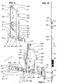
- FIG. 2 shows a cut-open floor guide unit 150, 160.
- the floor guide unit 150, 160 is permanently sunk or embedded in the floor, thereby providing increased stability and, as a result, improved protection against burglary.
- the lower end section of the sliding leaf 4, 6 can be seen in the upper area. From this lower end portion of the sliding leaf 4, 6, a bottom bar 11, 13 protrudes downward.
- a sliding element 110, 130 is slipped over the bottom bar 11, 13 and is preferably fastened there.
- the bottom bar 11, 13 with sliders 110, 130 protrudes into a guide chamber 151 (see Fig. 2 ).
- the guide chamber 151 is formed by a floor guide profile 150 of the floor guide unit 150, 160.
- the floor guide profile 150 provides the guide chamber wall 152 . How out 2 As can be seen, the bottom bar 11, 13 contacts the guide chamber wall 152 via the slider 110, 130. The bottom bar 11, 13 with the slider 110, 130 protrudes 30 millimeters into the guide chamber 151, which is 40 millimeters deep. In this way, the sliding leaf 4, 6 is guided in the guide chamber 151 along the closing movement in the closing direction S.
- the closing direction S is in 2 perpendicular to the drawing plane.
- the floor guide profile 150 is let into a floor connection profile 160 .
- the floor guide profile 150 is in turn embedded in the floor and provides the bearing surfaces 153, on which bearing elements 161 of the floor connection profile 160 rest.
- the floor guide profile 150 and the floor connection profile 160 can be attached to one another and to the floor, for example screwed. Furthermore shows 2 the first and the second horizontal secondary closing edge N1, N2.
- FIG 3 shows the second sliding leaf 6 with parts of the first sliding leaf 4 in a perspective view from below. Only a vertical profile 40 of the first sliding leaf 4 is shown. This vertical profile 40 provides the first vertical closing edge 4a with a groove 41 . A second vertical profile 60 of the second sliding leaf 6 provides the second vertical closing edge 6a with a ridge 61 . Both the comb-like elevation 61 and the groove 41 run along the respective vertical profiles 40, 60 over the entire length of the vertical profiles 40,60.
- a door panel 67 for example made of glass, of the second sliding leaf 6 can also be seen on the left.
- a vertical closing profile 68 is provided at the left end of the second sliding leaf 6 opposite the second vertical profile 60 .
- the vertical end profile 68 and the second vertical profile 60 are connected via a horizontal profile 69 .
- the first sliding leaf 4 also has a vertical end profile and a horizontal profile in a similar way, which are shown in 3 are not shown.
- the vertical profiles 40, 60 are preferably made of metal or plastic or a combination of these materials or other dimensionally stable materials known to those skilled in the art, are therefore extremely dimensionally stable and burglar-resistant, and extend from the floor to the lower end of the skylight 5.
- the walls of the vertical profiles 40 , 60 are 2 to 5 millimeters thick.
- the vertical profiles 40, 60 are essentially 100 millimeters wide, having a material thickness in the passage direction D of 25 to 100 millimeters, in particular 35 millimeters.
- the horizontal profile 69 and the vertical end profile 68 have the same material thickness in the passage direction D.
- the height of the horizontal profile 69 is 50-120 millimeters, its length in the closing direction S up to 200 centimeters.
- the vertical closing profile 68 also extends from the floor to the lower end of the skylight 5 and has a width in the closing direction S of essentially 100 millimeters.
- the second horizontal closing edge 6b is provided by the lower ends of the vertical profile 60, the vertical end profile 68 and the horizontal profile 69.
- a recess 65 is arranged on the second horizontal closing edge 6b (which is basically a mirror image of the horizontal closing edge 4b or the main closing edge H). Furthermore, in 3 the floor bars 11, 13 can be seen, which engage in the recess 65 and in the vertical profile 60 and the vertical end profile 68 (see below and 4 ).
- the first vertical profile 40 and the vertical end profile assigned to it also each have a bottom bar, which for the sake of clarity is shown in 3 are not shown; What follows for the bottom bars 11, 13 of the second sliding sash 6 also applies accordingly to the bottom bars of the first sliding sash 4.
- the bottom bar in the first vertical profile 40 is shaped and attached with respect to the main closing edge H essentially mirror-symmetrically to the bottom bar 11 in the second vertical profile 60 .
- the two bottom bars in the vertical profiles 40, 60 are then directed towards one another with respective projections 116. These projections complete the construction below the main closing edge H in the closing direction S.
- respective first horizontal legs 111, 131 and second vertical legs 112, 132 of the L-shaped bottom bar 11, 13 are shown. These first legs 111 and 131 are fitted in the recess 65 and are used to fasten the floor bars 11, 13 in the sliding sash 6.
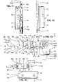
- figure 4 shows an exploded view of the second sliding leaf 6 with floor bars 11, 13.
- the second vertical profile 60 is shown with the vertical chamber 62 running vertically upwards.
- the vertical closing profile 68 with a further, vertically running chamber 66 is shown on the left-hand side.
- a first bottom bar 11 is shown on the right.
- the L-shaped floor bar 11 has an engagement element 118 with a slide element 110.
- the engagement element 118 with slide 110 can be inserted into the guide chamber 151 of the floor guide profile 151 (see 2 ).
- the first leg 111 of the bottom bar 11 extends horizontally beyond the engagement element 118 and is intended for mounting the bottom bar 11 in the recess 65 .
- the second leg 112 of the bottom bar 11 runs in the vertical direction V and can be inserted laterally with a precise fit into the vertical chamber 62 of the vertical profile 60 .
- the two legs 111, 112 extend approximately as far beyond the engagement element 118 as the latter is long.
- the bottom bar 11 has screws 115 by means of which the bottom bar 11 inserted into the sliding leaf 6 can be securely fixed in the vertical profile 60 .
- the engagement element 118 extends in the closing direction S over a length of approximately the width of the vertical profile 60 over the engagement element 118.
- the engagement element 118 is guided over the projection 116 (a section of the engagement element 118) to below the ridge 61.
- Bottom bars which are arranged opposite each other over the main closing edge H, close the gap below the main closing edge H by means of these projections 116.
- the screws 114 are provided on the first leg 111, by means of which the plate 113 is attached to the bottom bar 11 is attached. This plate 113 is then inserted to the depth of the groove 65 and ensures that the floor bar 11 is held in the correct vertical position.
- the second floor bar 13 is shown, which is designed to be essentially mirror-symmetrical to the first floor bar 11 .
- this floor bar 13 also has an L-shape with an engagement element 138, with a first leg 131 which runs horizontally over the engagement element 138 and with a second leg 132 which protrudes vertically over the engagement element 138.
- a plate 133 is fastened to the first leg 131 by means of screws 134 .
- the plate 133 like the plate 113, is placed in the depth of the groove-like recess 65.
- the second, vertical leg 132 can be inserted into the vertically running chamber 66 of the vertical connection profile 68 and can be fixed there.
- the legs 112 and 132 are each 50 millimeters to 200 millimeters long, e.g. 10 millimeters wide (in the closing direction S) and e.g. 30 millimeters to 40 millimeters thick (in the passage direction D), the latter depending on the corresponding thickness of the vertical profiles 40, 60 depends.
- This massive construction inserts the legs 112 and 132 deeply into the vertical profiles 40, 60 and the corresponding vertical end profiles 68.
- This configuration stabilizes the frame 68 , 69 , 60 of the sliding leaf 4 , 6 and ensures that the sliding leaf 4 , 6 is guided in the floor guide profile 150 by means of the engagement elements 118 , 138 . In addition, it is efficiently prevented that the sliding sash 4, 6 is pushed or pulled transversely to the running direction from the intended position.
- the second vertical closing edge 6a of the vertical profile 60 is shown at the top right.
- the ridge 61 which extends in the vertical direction V, is clearly visible.
- This elevation 61 is introduced as a tongue according to the tongue and groove principle in the groove 41 of the vertical profile 40 and represents, so to speak, a counter sealing profile to the groove 41.
- the locking device 20 consists of a U-forend plate 22 which is inserted or pushed into the groove 41 of the vertical profile 40 and which (with the outside 222) provides the rear limitation in the depth of the groove 41.
- FIG 5 the second sliding leaf 6 with the closing device 20 is shown.
- the vertical profile 60 with the ridge 61 can be seen and it can be seen that the ridge 61 extends from the bottom all the way up.
- the forend plate 22 is shown in a position in which it comes to rest when the vertical profiles 40, 60 engage in one another, ie when the vertical closing edges 4a, 6a are in mutual contact in the closed position.
- the U-forend plate 22 is in the vertical profile 40, which is figure 5 is not shown housed.
- Swivel lock boxes 21, 23, 26, 27, sliding blocks 220 and the motor 50 are attached to an inner side 221 of the forend plate 22 (see also below and 10 ). The elements just mentioned are thus accommodated in the vertical profile 40 .
- the swivel lock boxes 21, 23, 26, 27 are known, for example, from the prior art and surround a swivel lock 211, 231, 261, 271, which can be swiveled in a forward swivel movement, in this case in the direction of the vertical profile 60.
- the motor 50 is supplied and controlled via a control and/or feed line 51 which is connected to the motor 50 via a plug 52 .
- figure 6 shows an enlarged section figure 5 the vertical profile 60 has been omitted for clarity.
- the U-forend plate 22 can be seen again, on which the sliding blocks 220 and the swivel bolt boxes 21, 23 are visible.
- figure 7 shows a similar situation, looking at the outer surface 222 of the U-forend plate 22 from the left.
- swivel bolt boxes 21 and 23 are also referred to here. What was mentioned should then also apply to the other swivel bolt boxes 26 and 27, where appropriate.
- a pivot bolt 211, 231 is fitted in each pivot bolt box 21, 23. This pivoting bolt 211, 231 can be guided in a pivoting movement out of the pivoting bolt box 21, 23 through a recess 224, 223 through the U-shaped forend plate 22 (by means of a drive rod 55, see below).
- the extended swivel bolts 211, 231 protrude beyond the U-shaped forend plate 22 on its outside 222 and engage in a locking bar 29 arranged in the comb 61 opposite the forend plate.
- the bolts 211, 231 engage behind the locking bar 29 in each case, so that a form fit is realized in a direction parallel to the closing direction S.
- Respective engagement recesses 291, 292 are attached in the locking strip 29 for this engagement.
- Preferably one recess 291,292 is provided per latch 211,231. Since the locking bar 29 is mounted in a vertical chamber 63 in the comb 61 (see below), the comb 61 has openings at the locations of the recesses 291, 292 of the locking bar 29, so that the bolts 211, 231 can be inserted into the comb 61 and the one behind it Closing bar 29 can intervene.
- the pivot bolt 211, 231 is thus pivoted through the recess 291, 292 behind the closing strip 29.
- the hook-like design of the pivot bolt 211, 231 enables the pivot bolt 211, 213 to engage behind the locking bar 29.
- the locking strip 29 is firmly attached to or on the second vertical profile 60 (in the comb 61).
- the vertical profiles 40, 60 can thus be locked against one another by means of the swivel bolts 211, 231 and the closing strip 29, so that an opening movement (in particular along the closing movement) of the sliding leaves 4, 6 is prevented.
- a mushroom pin 212, 232 is attached in each case.
- This mushroom pin 212, 232 protrudes in each case (up to about 20 millimeters) towards the depth of the vertical profile 40.
- the retaining plate 24 is shown, which provides recesses 241, 243.
- the mushroom pins 212, 232 and the retaining plate 24 now form a bayonet catch via these recesses 241, 243 with a positive fit parallel to the S direction.
- the bayonet lock is useful for efficient assembly.
- the retaining plate 24 protrudes beyond the swivel bolt boxes on the broad side, as does the U-forend plate 22, which can be seen from the figures mentioned.
- figure 8 shows the U-forend plate 22 with the pivot bolt boxes 21, 23, which protrude backwards on the inside 221 of the U-forend plate 22 into the depth of the chamber 44a, 44b.
- the retaining plate 24 is also shown.
- the vertical profile 40 can also be seen. It can be seen that the U forend plate 22 can be pushed into the profile 40 .
- the retaining strip 24 can be inserted vertically into the profile 40.
- the vertical profile 40 has corresponding recesses in the vertical chamber 42 (for example in the partition wall 421, see below).
- the vertical profile 40 therefore has the vertical chamber 42 to accommodate the elements mentioned.
- This vertical chamber 42 closes in 8 right to the inside 221 of the U-forend plate 22, wherein the groove 41 extends from the other side, the outside 222 of the U-forend plate 22 to the left.
- the groove 41 is delimited by an outer flank 41a and an inner flank 41b and the outside of the U-shaped forend plate.
- the expression “outer” or “inner” refers to the respective arrangement of the flank 41a, 41b with respect to the outside or the inside of the building opening, which can be closed by the system 1.
- flanks 41a and 41b are in 13 evident. These flanks 41a and 41b have free ends 41f and 41g, respectively. At the free ends 41f, 41g, the flanks 41a, 41b are 4 millimeters thick or thick (in passage direction D), this thickness or material thickness increasing towards the rear (ie towards the forend plate 22) by 25% to 30%. The corresponding edges can each be rounded.
- flanks 41a, 41b overlap in such a way that unauthorized access via the main closing edge H (i.e. the vertical closing edges 4a, 6a) to parts of the closing device 20 (e.g. by means of a lever tool such as a "cow's foot") is made more difficult, which has a burglary-resistant effect.
- a vertical gap 41e (see Fig. 3 ), which exists between the free ends 41f, 41g of the flanks 41a, 41b and the vertical profile 60 in the closing direction S (see 13 ) should therefore be minimal, here (with vertical profiles 35 millimeters thick in the D direction) the gap is then less than 1 millimeter wide.
- flanks 41a, 41b should be stable and thick enough to withstand a violent attempted break-in for as long as possible.
- the crest 61 is preferably formed on the vertical profile 60 in such a way that the flanks 41a, 41b engage in the vertical profile 60 to the side of the crest 61 (i.e. in direction D), so that against the outside (and preferably also the inside) a flush surface 46 (see 3 ) is formed. This minimizes the number of possible points of attack for lever tools or striking tools.
- the groove 41 is delimited by the outside 222 of the forend plate 22 at a depth of 11.5 millimeters.
- the chambers 42 adjoin the groove 41 on the inside 221 of the 1 to 3 millimeter thick U-shaped forend plate 22 opposite the outside 222 and extends both in the vertical direction V and 20 to 100 millimeters in depth, i.e. in the opposite direction the closing direction S of the closing leaf 4, in the vertical profile 40.
- both vertical profiles 40 and 60 are shown. It can be seen that the vertical profile 60 also has a vertical chamber 62 . As in 9 can also be seen, a partition 621, which runs in the vertical direction, divides the vertical chamber 62 into two vertical partial chambers 63 and 64 (this partition 621 corresponds to the partition 421 in the first vertical profile 40, see below.).
- the first sub-chamber 63 extends from the rear into the ridge 61.
- the second sub-chamber 64 is lower (i.e. further back, opposite to the closing direction S) in the vertical profile 60 than the first sub-chamber 63 and has vertical webs 642 attached laterally in the center with respect to the closing direction , which extend into the chamber 62 from the edge.
- the first and second partial chambers 63, 64 run all the way down in the vertical profile 60 and are open at the bottom.
- the bottom bar 11 is inserted into the vertical profile 60 from below.
- the vertically standing second leg 112 is introduced into the first sub-chamber 63 and rests against the partition wall 621 at the rear. This is also in 13 recognizable.
- figure 13 shows a top view of interlocking vertical profiles 40, 60 with elements of the locking device 20 and elements of the bottom bar 11. It can be seen that the vertically standing second leg 112 is pushed into the chamber 63 close to the partition wall 621.
- the locking bar 29 is also inserted into the partial chamber 63 .
- the locking bar 29 is pushed into the front area of the sub-chamber 63 and contacts the comb 61 from behind (see also 13 ).
- the comb 61 has passage openings from the outside through the recesses 291, 292 into the partial chamber 63 at the appropriate points.
- a sealing profile 8 is provided near the end regions of the flanks 41a, 41b of the groove 41, which laterally enclose the elevation 61.
- This sealing profile 8 is attached to the end of the comb 61 on the vertical profile side and makes sealing contact with the free ends of the flanks 41a, 41b when the sliding leaves 40, 60 are closed. It's further into the figs 9 and 13 recognizable that the closing strip 29 is inserted into the foremost section of the sub-chamber 63, this foremost part of the sub-chamber 63 encompassing the closing strip 29 to the rear, so that the closing strip 29 is positively locked in the closing direction S.
- the vertical profile 40 On the right in 9 the vertical profile 40 is shown.
- the vertical chamber 42 can be seen, which is divided into two vertical chambers 43 and 44a, 44b by a partition wall 421.
- the vertical sub-chamber 44a, 44b has a second vertical web 442 in the center with respect to the closing direction S, and a first vertical web 441 behind the second vertical web 442.
- the second vertical profile 60 has a corresponding vertical web 641.
- the vertical webs 441, 442, 641, 642 run parallel to the groove 41 and the ridge 61.
- the holding strip 24 is inserted into the vertical partial chamber 44a, 44b, specifically between the first vertical web 441 and the second vertical web 442 and is thus parallel in one direction found positively to the closing direction S.
- the retaining strip 24 spans the vertical profile 40 in the entire clear width (in direction D) and thus divides the sub-chamber 44a, 44b into a front sub-chamber 44a and a rear sub-chamber 44b (see also Fig.13 ).
- retaining strip 24 In order to fix the retaining strip 24 vertically, screws 293 running essentially horizontally penetrate the retaining strip 24 from the front to the rear, with the screws 293 protruding backwards over the retaining strip 24 .
- a rear wall of the vertical partial chamber 44b can then have threaded holes (or provide corresponding means) in which the holding strip 24 is fixed by means of screws 293.
- the retaining strip 24 can also be fixed vertically in another way that is obvious to a person skilled in the art.
- Several holding strips 24 (and/or closing strips 29) can also be provided in the vertical profiles 40 (or in the profile 60), depending on the number of swivel bolt boxes.
- figure 13 shows that the U-forend plate 22, which is inserted from the front into the groove 41 and limits the depth of the groove 41 to the rear, and the sliding blocks 220, which are inserted in a form-fitting manner into the sub-chamber 43 and can be moved vertically, interact in a form-fitting manner.
- the sliding blocks 220 are fixed by screws, which run from an outside 222 through the U-forend plate 22 into the sliding blocks 220.
- the sliding blocks 220 are inserted in the vertical sub-chamber 43 and lie in the closing direction S from behind on a vertically running web 41c of the vertical profile 40 .
- the U-forend plate 22 rests on these webs 41c from the front.
- the U-forend plate 22 thus holds the two flanks 41a, 41b together in a form-fitting manner with respect to the passage direction D; In other words, the U-forend plate 22 surrounds the two vertical webs 41c. This increases the stability of the flanks 41a, 41b and counteracts the flanks from bending open or breaking up from the outside (with respect to the groove 41). It is therefore also preferred that the forend plate extends over the entire length of the groove 41 and secures the engagement of the groove 41 and the ridge 61 . In this case, a form fit is realized in a direction parallel to the closing direction S.
- FIG 10 shows the U-forend plate 22 with four mounted swivel bolt boxes 21, 23, 26, 27 (an upper pair 26, 27 and a lower pair 21, 23).
- locking pins 25 are attached on the outside 222 of the U-forend plate 22 .
- Such a locking pin 25 is also in the lower part of 7 recognizable.
- these pins 25 also called centering pins 25
- pivoting bolt boxes 21, 23 are arranged such that the lower pivoting bolt 211, 231 of the lower pivoting bolt boxes 21, 23 are guided in a pivoting movement, which leads from bottom to top.
- the upper pivoting bolt boxes 26, 27 are reversed (that is to say in opposite directions) so that their pivoting bolts 261, 271 perform a pivoting movement pointing from top to bottom.
- This mirror-symmetrical arrangement prevents the locked sliding leaves 4 , 6 from being able to be moved upwards or downwards and thus the swivel bolts 211 , 231 , 261 , 271 being simply lifted out of the corresponding recesses in the locking bar 29 .
- the drive rod 55 which in the figs 5, 6 , 8, 9 is recognizable.
- This connecting rod 55 is linearly movable, with its linear movement being transformed in the pivoting bolt boxes 21, 23, 26, 27 in such a way that the pivoting bolts 211, 231, 261, 271 carry out their corresponding pivoting movements.
- the motor 50 can be provided to actuate this connecting rod 55 (see e.g. figure 5 ) or the connecting rod 55 can be operated manually. Instead of the motor, it is also possible, for example, to use an electromagnet or other electrically operated elements to actuate the drive rod 55 . So it is both a version for automatic and one for manual operation possible.
- a middle lock 70 which serves as the main lock 70 .
- This main lock 70 has a lock cylinder 71 in which, for example, a key can be inserted. If the key fits, the drive rod 55 can be actuated either manually or automatically via the motor 50 by means of a corresponding rotational movement of the key via a known locking mechanism.
- anti-drill plates 73, 74 In order to make unauthorized access to the drive rod 55 and the main lock 70 from the outside even more difficult, anti-drill plates 73, 74, as in 11 visible, protectively attached. These drilling protection plates 73, 74 block access to the drive rod 55 and are preferably made of steel and are several millimeters thick.
- figure 12 shows the center lock 70 in a view from the front and its arrangement relative to the U-forend plate 22. Part of the lock cylinder 71 and the cover 72 can be seen from the front.
- figure 14 shows the object of in a view 12 from underneath. It shows the center lock 70 with the lock cylinder 71 and the cover 72 as well as the U-forend plate 22 with mounted swivel bolt box 21 and to the right adjoining mushroom pin 212, which engages through a corresponding recess in the holding strip 24 and passes through it.
- figure 15 shows a perspective side view from the front bottom left of the second sliding leaf 6 with the vertical end profile 68 and the door panel 67.
- figure 16 shows an enlarged section of the illustration 15 from a more frontal perspective. Also note this 17 , which the subject after 15 shows from the side. For the sake of clarity, the hatching of the section has been 17 each omitted.
- an upper horizontal profile 33 is provided in the upper end area of the sliding leaf 6, which extends between the second vertical profile 60 and the vertical end profile 68 (parallel to the lower horizontal profile 69 at the upper end of the door panel). Also in 17 below is the door leaf 6 of the Sliding leaf 6 can be seen, to which the upper horizontal profile 33 connects to the top. The upper horizontal profile 33 is firmly connected to the sliding leaf 6 in question.
- the horizontal profiles 33, 69, the second vertical profile 60 and the vertical end profile 68 thus form a peripheral frame in which the door panel 67 of the wing 6 is provided.
- the details described here can also apply to the first sliding leaf 4, which (up to about a mirror-image design) depending on the embodiment can differ structurally from the second sliding leaf 6, for example essentially only in the area of the vertical profile 40.
- the sliding panel 6 is fastened to two carriages 32 via the upper horizontal profile 33, which essentially extends horizontally between the vertical end profile 68 and the second vertical profile 60.
- a secure screw connection screws 313 is preferred for this purpose.
- a stationary fixed running profile 31 with a rail profile 30 is provided for the suspension of the sliding doors 4, 6 (see in particular figs 15 , 17 ), which provides means for suspension and guidance of the carriage 32.
- the running profile 31 provides a leg 310 running horizontally along the closing movement of the sliding leaf 6 .
- the leg 310 has a free-standing end on the upper side of which a rail 311 for the carriages 32 is provided.
- the carriages 32 have running wheels 321 which provide a concave running surface. If the carriage 32 is placed on the rail 311, this engages in the concave running surfaces of the running wheels 321 according to its convex cross-sectional shape. There are 2 or 3 such wheels 321 provided per carriage 32 here.
- the rail 311 can also be concave and the respective running surface of the running wheel 321 can be convex in shape, which enables a similar intervention, which has a laterally guiding effect. Thanks to this configuration, the sliding leaf 6 can be pivoted perpendicularly to the closing movement over a limited angular range without the forces acting thereby causing damage to the rail 311, rail profile 30 and/or running wheels 321.
- a first anti-lift device 322 is provided in the form of a metal plate 322, which protrudes upwards from the carriage body of the carriage 32 and the mentioned lifting movement of the leaf 6 upwards (see Fig . 17 ) limited by the fact that the plate 322 is present at the top of the running profile 31, forming a flat contact. Contact surfaces of this contact forming the stop are preferably rough, so that it is difficult or impossible to move the lifted sliding leaf 6 pressing the plate 322 against the running profile 31 along the closing movement into the open state.
- This plate 322 may be vertically offset from a pivot point (defined by rail 311) (see Fig. 17 , plate 322 is offset to the right). However, it is also conceivable that the plate 322 is attached in a different way (and thus contacts another preferably stationary element); it is important that the plate 322 supports the lifting movement of the carriage 32 (in 17 to the right and up) and the wing 6 limited. Each carriage 32 can provide at least one stop 322 .
- the carriages 32 make rolling contact with the running profile 31 via the rail 311 which is provided on a leg 310 of the running profile 31 which protrudes horizontally from the running profile 31 and runs parallel to the closing direction S.
- the carriage 32 then extends with the carriage body in front of the leg 310, as described above, at least partially upwards and also over a wing adaptation angle 34 to below the leg 310 (see Fig. Figures 15-17 ).
- a plate-like second anti-lever device 324 is attached to the bottom of the leg 310 in the area above the adaptation angle 34 of each carriage 32 in the closed position.
- the second anti-lift device 324 extends downwards under the rail 311 and provides a stop for the respective adaptation bracket 34, which allows the sliding sash 6 to pivot to both sides in the passage direction D (in 17 left and right) limited.
- the second anti-lift device 324 (as in 17 indicated) composed of several plates, preferably made of metal or plastic. These plates can be 3 to 15 millimeters thick, for example.
- the overhang of the anti-leverage device 324 can be adjusted downwards over the leg 310 . With which the distance between the locking screws 313 or adaptation bracket 34 and the second anti-lever device 324 can be adjusted.
- the essentially U-shaped adaptation bracket 34 encompasses the second anti-leverage device 324 at the bottom and is located behind the second anti-leverage device 324 (on the left in 17 ) via a section 341 back up.
- the section 324 of the adaptation bracket 34 strikes the second anti-lever device 324 on the left.
- the adaptation bracket 34 swings in the right-hand area of the second anti-lift device 324 (see Fig 17 ) and/or the section 341 strikes the profile 30 (or an associated screw) on the left.
- the locking screws 313 limit these pivoting movements to the left and to the right or support or secure the limiting effect.
- the locking screws 313 also hit the second anti-leverage device 324 and thus support the effect of the above-mentioned first anti-leverage device 322.
- an alternative geometry is chosen in a different way that is obvious to a person skilled in the art.
- the first and second anti-lever devices 322, 324 effectively make it more difficult to lever out the sliding sash, in particular in conjunction with the floor latches described above, which are guided in the floor guide 150, 160 along the closing movement.
Landscapes
- Engineering & Computer Science (AREA)
- Mechanical Engineering (AREA)
- Civil Engineering (AREA)
- Structural Engineering (AREA)
- Specific Sealing Or Ventilating Devices For Doors And Windows (AREA)
Claims (13)
- Installation de vantail coulissant (1), en particulier installation de porte coulissante automatique, comprenant au moins un vantail coulissant (4 ; 6), le vantail coulissant (4 ; 6) pouvant être coulissé dans un dispositif de guidage de plancher (150, 160) le long d'un déplacement de fermeture de manière à fermer une ouverture d'un bâtiment dans une direction de passage (D) et fournissant dans une direction de fermeture (S) sensiblement horizontale une première arête verticale de fermeture (4a), et l'installation de vantail coulissant (1) fournissant une seconde arête verticale de fermeture (6a), la première arête verticale de fermeture et la seconde arête verticale de fermeture (4a, 6a) pouvant être amenées mutuellement en contact fermant, et le vantail coulissant (4,6) fournissant une arête horizontale de fermeture (4b, 6b), laquelle forme, avec le dispositif de guidage de plancher (150, 160), une arête horizontale secondaire de fermeture (N1, N2) s'étendant le long de la direction de fermeture (S),au niveau d'au moins une des arêtes verticales de fermeture (4a, 6a), au moins par sections, au moins un flanc extérieur indéformable (41a) constitué de métal ou de matière plastique ou d'une combinaison de ceux-ci, s'étendant sensiblement dans la direction verticale (V) et faisant saillie de manière libre dans la direction de fermeture (S) est pourvu, le flanc extérieur (41a) étant disposé de manière décalée en direction d'un côté extérieur de l'ouverture de bâtiment sur l'arête verticale de fermeture (4a, 6a) correspondante et formant une marche,respectivement à l'opposé de ce flanc extérieur (41a), au niveau de l'autre arête verticale de fermeture (6a, 4a), une crête indéformable (61) constituée de métal ou de matière plastique ou d'une combinaison de ceux-ci, correspondant à ce flanc extérieur (41a), s'étendant sensiblement dans la direction verticale (V) et faisant saillie dans la direction de fermeture (S) est disposée, cette crête (61) s'étendant de manière latéralement décalée par rapport au flanc extérieur (41a) en direction d'un côté intérieur de l'ouverture de bâtiment et peut être amenée en prise de contact avec la dite marche, sensiblement au niveau de sa profondeur, par le mouvement de fermeture le long d'un côté intérieur du flanc (41a) orienté dans la direction d'un côté intérieur de l'ouverture de bâtiment,un dispositif de fermeture (20) disposé au niveau de ces arêtes verticales de fermeture (4a, 6a), ayant au moins un point de verrouillage pour la fixation du vantail coulissant (4 ; 6) quand la première et seconde arête verticale de fermeture (4a, 6a) se trouvant mutuellement en contact fermant est fourni, le point de verrouillage étant fourni du côté de la crête, de sorte que le flanc extérieur (41a) recouvre le point de verrouillage dans la direction du côté extérieur de l'ouverture de bâtiment, la flanc (41a) faisant saillie de manière libre au-delà de l'arête verticale de fermeture (4a, 6a) dans la direction de fermeture (S) sur 10 millimètres à 30 millimètres et présentant une épaisseur de matière dans la direction de passage (D) qui est au moins 2 millimètres à 10 millimètres, caractérisée en ce que la crête (61) est disposé de manière décalée au niveau de l'arête verticale de fermeture (4a, 6a) correspondante par rapport au côté intérieur de l'ouverture de bâtiment, de sorte que le flanc extérieur (41a) fourni recouvrant la crête (61) dans la direction du côté extérieur de l'ouverture de bâtiment recouvre la crête (61), quand les arêtes verticales de fermeture (4a, 6a) sont en contact fermant, autant contre l'arête verticale de fermeture (4a, 6a) fournissant la crête(61) dans la direction de fermeture (S), qu'une fente verticale (41e) entre l'extrémité libre (41f) du flanc extérieur (41a) et l'arête verticale de fermeture (4a, 6a) fournissant la crête (61) est de moins de 2 millimètres, en particulier moins de 1 millimètre, et que dans une région autour de cette fente verticale (41e) une surface sensiblement alignée (46) en direction du côté extérieur de l'ouverture de bâtiment est formée.
- Installation de vantail coulissant (1) selon la revendication 1, caractérisée en ce que au niveau de l'arête verticale de fermeture (4a ;6a) fournissant le flanc extérieur (41a), un autre flanc intérieur (41b), qui s'étend sensiblement parallèlement au flanc extérieur (41a) et qui est disposé de manière décalée à une distance du flanc extérieur (41a) dans la direction du côté intérieur de l'ouverture de bâtiment dans la direction de passage (D), ce flanc intérieur (41b) faisant saillie dans la direction de fermeture (S) préférablement sensiblement à même distance que le flanc extérieur (41a), une rainure (41) s'étendant de manière verticale étant formée entre le flanc extérieur (41a) et le flanc intérieur (41b), de sorte que cette rainure (41) et la dite crête (61) peuvent être amenées mutuellement en prise par le mouvement de fermeture, cet engagement s'étendant par sections, prises ensemble, sur au moins la moitié de l'étendue longitudinale des arêtes verticales de fermeture (4a, 6a) et de préférence cette crête (61) s'étendant sensiblement sur la largeur libre de la rainure (41) dans la direction de passage (D) et sensiblement sur une longueur de la rainure (41) dans la direction verticale (V) et, lors de la prise dans la rainure (41), vient en prise de préférence sensiblement jusqu'à une profondeur de la rainure (41).
- Installation de vantail coulissant (1) selon l'une des revendications précédentes, caractérisée en ce que le flanc présente une épaisseur de matériel dans la direction de passage (D), qui est supérieure à 3 millimètres, en particulier 4 millimètres ou plus, et s'effilant dans la direction d'une extrémité libre (41f, 41g) du flanc (41a ; 41b).
- Installation de vantail coulissant (1) selon l'une des revendications 2 à 3, caractérisée en ce que les flancs (41a, 41b) sont des flancs (41a, 41b) s'étendant de manière espacée l'un de l'autre dans la direction de passage (D) de préférence par au moins 10 mm ou plus, en particulier par 20 à 90 mm, de préférence sensiblement en continu le long de l'arête verticale de fermeture (4a), ces flancs (41a, 41b) étant disposés de préférence au niveau de régions d'extrémité opposées en direction de passage (D) de l'arête verticale de fermeture correspondante (4a, 6a), et la rainure (41) formée par les flancs (41a, 41b) présente une profondeur dans une direction parallèle à la direction de fermeture (S) d'au moins 10 millimètres à 30 millimètres ou plus et une largeur libre dans la direction de passage (D) d'au moins 10 millimètres ou plus, en particulier de 20 à 90 millimètres.
- Installation de vantail coulissant (1) selon l'une des revendications 2 à 4, caractérisée en ce que le dispositif de fermeture (20) fournit au niveau d'une des dites arêtes verticales de fermeture (4a ; 6a), de préférence dans la crête (61) ou dans la profondeur de la rainure (41), au moins un évidement de prise (291 ; 292) étant ouvert en continu vers l'extérieur dans la direction de fermeture (S), et que le dispositif de fermeture (20) présente au moins un boulon (211 ; 231 ; 261 ; 271) monté sur l'autre arête verticale de fermeture (4a ; 6a) et de préférence disposé dans la profondeur de la rainure (41) ou dans la crête (61),lequel, quand les arêtes verticales de fermeture (4a, 6a) sont en contact fermant, peut être tourné, pivoté et/ou coulissé jusque dans le dit évidement de prise (291; 292) pour verrouiller le vantail coulissant (4 ;6) et pour une prise par engagement positif par rapport à une direction parallèle à la direction de fermeture (S), le dit évidement de prise (291 ; 292) et le boulon correspondant (211 ; 231 ; 261 ; 271) formant un point de verrouillage.
- Installation de vantail coulissant (1) selon la revendication précédente, caractérisée en ce que les arêtes verticales de fermeture (6a, 4a) fournissent au moins deux points de verrouillage espacés verticalement et formant une paire, une distance entre ces deux points de verrouillage étant de préférence de 50 millimètres à 250 millimètres ou moins, en particulier sensiblement 150 millimètres, deux paires ou plus de points de verrouillage de préférence étant disposées de manière distribuée sur les arêtes verticales de fermeture (41, 6a).
- Installation de vantail coulissant (1) selon l'une des deux revendications précédentes, caractérisée en ce que le dispositif de fermeture (20) fournit au moins une bande de fermeture (29) étant disposée dans la crête(61) et s'étendant de préférence verticalement, qui entoure au moins partiellement, de préférence complètement, l'évidement de prise (291 ; 292) et que le dispositif de fermeture (20) présente au moins une boîte à boulon pivotant (21 ; 23 ; 26) disposée dans la profondeur de la rainure (41), comportant un boulon pivotant (211 ; 231 ; 261 ; 271) qui est monté de manière pivotante le long d'un mouvement de pivotement et qui, quand les arêtes verticales de fermeture (4a, 6a) sont en contact, depuis le boîtier de boulon pivotant (21 ; 23 ; 26 ; 27) jusqu'à l'évidement de prise respectif (291 ; 292) vers une position de verrouillage, le boulon pivotant (211 ; 231 ; 261 ; 271) venant en prise de préférence derrière la bande de fermeture (29) en position de verrouillage, et ce boulon pivotant (211 ; 231 ; 261 ; 271) étant de préférence formé en acier et l'acier ayant une épaisseur de matériel d'au moins 3 à 8 millimètres ou plus.
- Installation de vantail coulissant (1) selon l'une des revendications précédentes, caractérisée en ce qu'au niveau de l'arête horizontale secondaire de fermeture (N1 ; N2) de l'au moins un vantail coulissant (4 ; 6) pouvant être coulissé, au moins un boulon de plancher (11 ; 13) avec un élément d'engagement (118 ; 138) est fourni, l'élément d'engagement (118 ; 138) faisant saillie de manière libre vers le bas de préférence de 5 millimètres à 50 millimètres de l'arête horizontale secondaire de fermeture (N1 ; N2) et s'étend de préférence sur 50 à 200 millimètres le long de la direction de fermeture (S), en ce que le dispositif de guidage de plancher (150, 160) fournit un profilé de guidage de plancher (150) le long du mouvement de fermeture avec une chambre de guidage (151) ouverte vers le haut, limitée dans la direction de passage (D) par une paroi de chambre de guidage (151) et correspondant avec le boulon de plancher (11 ;13), de préférence un profilé de raccordement au plancher (160) encastré dans le plancher étant prévu pour recevoir le profilé de guidage de plancher (150), l'élément d'engagement (118 ; 138) du boulon de plancher (11;13) faisant saillie sensiblement sur sa hauteur de saillie dans la chambre de guidage (151), et guidant le vantail coulissant (4 ; 6) pouvant être coulissé, pouvant être déplacé de manière coulissante le long du mouvement de fermeture, le boulon de plancher (11 ; 13) étant de préférence en contact avec la paroi de la chambre de guidage (152) par un élément coulissant (110 ; 130).
- Installation de vantail coulissant (1) selon l'une des revendications précédentes, caractérisée en ce que l'installation de vantail coulissant (1) comprend au moins un premier vantail coulissant (4) et un second vantail coulissant (6) mobile en sens inverse pour fermer l'ouverture de bâtiment, lesquels sont coulissants dans le dispositif de guidage de plancher (150,160) le long du mouvement de fermeture et parallèlement à la direction de fermeture (S), en ouvrant ou fermant l'ouverture de bâtiment, le premier vantail coulissant (4) fournissant la première arête verticale de fermeture (4a) dans la direction de fermeture (S) et le second vantail coulissant (6) fournissant la seconde arête verticale de fermeture (6a) dans la direction de fermeture (S).
- Installation de vantail coulissant (1) selon l'une des revendications 2 à 9 précédentes, caractérisée en ce que la première arête verticale de fermeture (4a) est fournie par un premier profilé vertical (40) et la seconde arête verticale de fermeture (6a) est fournie par un second profilé vertical (60), ces profils verticaux (40,60) étant de préférence en métal ou en matière plastique ou une combinaison de ceux-ci et s'étendant de préférence de 40 à 200 millimètres, de préférence sensiblement 100 millimètres, dans la direction de fermeture (S) et de 20 à 100 millimètres, de préférence 35 millimètres, dans la direction de passage (D) et de préférence sensiblement sur une hauteur totale de l'ouverture, et qu'un des premier et second profils verticaux (40 ;60) fournit l'au moins une rainure (41) s'étendant de préférence le long de toute l'arête verticale de fermeture (6a ; 4a) et l'autre profil vertical (60 ; 40) prévoit la crête (61) correspondante à cette rainure (41), s'étendant de préférence sensiblement le long de toute la rainure (41), la rainure (41) étant de préférence réalisée de manière à s'élargir dans la direction de fermeture (S).
- Installation de vantail coulissant (1) selon l'une des revendications précédentes 6 à 10, caractérisée en ce qu'une plaque de contact (22) qui s'étend dans la direction verticale (V) et fixée positivement au moins par rapport à une direction parallèle à la direction de fermeture (S), qui maintient de préférence ensemble les flancs (41a, 41b) de la rainure (41), limite la rainure (41) en profondeur, en ce qu'une chambre verticale (42) s'étendant vers l'arrière dans le vantail coulissant (4) est prévue sur un côté intérieur (221) de cette plaque de contact (22) opposé à l'arête verticale de fermeture (4a), et en ce que, depuis ce côté intérieur (221) de la plaque de contact (22), dépassant dans une profondeur de la chambre verticale (42) à l'opposé de la direction de fermeture (S), l'au moins une boîte à boulon pivotant (21 ; 23 ; 26 ; 27) est montée avec un boulon à pivotement (211 ; 231 ; 261 ; 271), le boulon de pivotement (211 ; 231 ; 231 ; 261 ; 271) pouvant pivoter dans un mouvement de pivotement hors de la boîte à boulons de pivotement (21 ; 23 ; 26 ; 27) par un évidement (224 ; 223) dans la plaque de contact (22) dans la rainure (41) et, quand les arêtes verticales de fermeture (4a, 6a) se referment, dans l'évidement (291 ; 292), et de préférence pouvant être verrouillé dans un étant pivoté.
- Installation de vantail coulissant (1) selon l'une des revendications précédentes, caractérisée en ce qu'une tige d'entraînement (55) est prévue au moyen de laquelle le dispositif de fermeture (20) peut être actionné manuellement par un verrou central ou automatiquement par un moteur (50), par un électroaimant ou par un autre moyen électro-propulsé, et en ce que de préférence au moins deux paires de boîtes à boulon pivotant (21, 23, 26, 27) sont fournies, une paire inférieure de boîtes à boulon pivotant (21, 23, 26, 27) étant montée en dessous du verrou central (70) et/ou du moteur (50), et une paire supérieure de boîtes à boulon pivotant (21, 23, 26, 27) étant montée en dessus du verrou central (70) et/ou du moteur (50), les boulons à pivotement (211, 231, 261, 271) étant prévus de préférence par paires suivant des mouvements pivotants différents, les mouvements pivotants différant en particulier en ce que le boulon à pivotement (211, 231, 261, 271) peut être pivoté depuis le bas vers le haut ou bien depuis le haut vers le bas dans l'évidemment (291, 292) respectif de la bande de fermeture (29).
- Installation de vantail coulissant (1) selon l'une des revendications précédentes, caractérisée en ce qu'un dispositif anti-dégondage est disposée en dessus de l'au moins un vantail coulissant (4, 6) lequel est au moins quand l'ouverture de bâtiment est fermée, limite un soulèvement du vantail coulissant (4,6) dans la direction verticale (V) et/ou un pivotement du vantail coulissant (4,6) dans la direction de passage (D), en particulier afin de dégonder du boulon de plancher (11, 13), en particulier du boulon de plancher (11,13) selon la revendication 9, respectivement au moyen de butée du dispositif anti-dégondage (322, 324) contre un élément disposé en face du dispositif anti-dégondage (322, 324), où cet élément disposé en face est constitué en particulier par des parties de profilé de guidage (31) ou de chariot de pour le déplacement de ce vantail coulissant (4, 6).
Applications Claiming Priority (2)
| Application Number | Priority Date | Filing Date | Title |
|---|---|---|---|
| CH8762012 | 2012-06-21 | ||
| PCT/EP2013/061671 WO2013189749A1 (fr) | 2012-06-21 | 2013-06-06 | Porte coulissante anti-effraction |
Publications (4)
| Publication Number | Publication Date |
|---|---|
| EP2864566A1 EP2864566A1 (fr) | 2015-04-29 |
| EP2864566B1 EP2864566B1 (fr) | 2018-11-28 |
| EP2864566B8 EP2864566B8 (fr) | 2019-01-02 |
| EP2864566B2 true EP2864566B2 (fr) | 2022-11-23 |
Family
ID=48577751
Family Applications (1)
| Application Number | Title | Priority Date | Filing Date |
|---|---|---|---|
| EP13727601.0A Active EP2864566B2 (fr) | 2012-06-21 | 2013-06-06 | Porte coulissante anti-effraction |
Country Status (4)
| Country | Link |
|---|---|
| US (1) | US20150159427A1 (fr) |
| EP (1) | EP2864566B2 (fr) |
| CN (1) | CN104411904A (fr) |
| WO (1) | WO2013189749A1 (fr) |
Families Citing this family (12)
| Publication number | Priority date | Publication date | Assignee | Title |
|---|---|---|---|---|
| WO2016083765A1 (fr) * | 2014-11-28 | 2016-06-02 | Fullex Locks Limited | Appareil conçu pour fixer deux éléments l'un à l'autre |
| WO2017025269A1 (fr) * | 2015-08-13 | 2017-02-16 | Gilgen Door Systems Ag | Dispositif de verrouillage pour châssis coulissant |
| DE102015113385A1 (de) | 2015-08-13 | 2017-02-16 | Gu Automatic Gmbh | Automatische Schiebetür mit einer Antriebseinheit und verfahrbaren Türflügeln |
| WO2017117760A1 (fr) * | 2016-01-06 | 2017-07-13 | 立兴杨氏实业(深圳)有限公司 | Dispositif de verrouillage |
| ES2688170B1 (es) * | 2017-03-31 | 2019-07-09 | Cabanero S L | Cerramiento deslizante inteligente anti-intrusión |
| US11739588B2 (en) * | 2017-05-12 | 2023-08-29 | Iph International Pty Ltd | Security door system |
| TWI733409B (zh) * | 2020-04-10 | 2021-07-11 | 上田鋁業有限公司 | 具有多點防撬結構之橫拉窗 |
| TWI725905B (zh) * | 2020-08-06 | 2021-04-21 | 晟鈺智能全球有限公司 | 具透氣功能之智能鎖固式門窗 |
| AT523946B1 (de) * | 2021-03-23 | 2022-01-15 | Elmer Hubert | Ganzglasanlage mit glasschiebetür |
| US20240368928A1 (en) * | 2023-05-02 | 2024-11-07 | PrevEntry USA LLC | Sliding door blocking system |
| CN116498160B (zh) * | 2023-06-13 | 2025-07-15 | 和能人居科技集团股份有限公司 | 一种推拉门锁紧组件 |
| DE102024204349A1 (de) | 2024-05-08 | 2025-11-13 | Roto Frank Fenster- und Türtechnologie GmbH | Rollwagen, Rollwagenanordnung und Fenster oder Tür, mit Haltesicherung |
Citations (13)
| Publication number | Priority date | Publication date | Assignee | Title |
|---|---|---|---|---|
| US3650071A (en) † | 1970-09-08 | 1972-03-21 | Southeastern Aluminum Products | Panel frame assembly |
| US4475313A (en) † | 1983-04-05 | 1984-10-09 | Peachtree Doors, Inc. | Locking arrangement for sliding doors |
| EP0572936A1 (fr) † | 1992-06-04 | 1993-12-08 | Karl Haab | Rail |
| US5452925A (en) † | 1994-06-30 | 1995-09-26 | Huang; Chien F. | Tightening latching device |
| DE10259924A1 (de) † | 2002-12-20 | 2004-07-15 | Geze Gmbh | Schiebetüranlage |
| US7059017B1 (en) † | 2005-01-04 | 2006-06-13 | Rosko Peter J | Sliding door assembly for track, step plate, roller, guide and constraint systems |
| DE19634391B4 (de) † | 1996-08-26 | 2008-06-12 | Dorma Gmbh + Co. Kg | Bodenverankerung für Flügel einer ortsveränderbaren Schiebeflügelwand aus Isolierglas |
| EP1936098A2 (fr) † | 2006-12-22 | 2008-06-25 | GEZE GmbH | Installation de porte automatique |
| US20080148790A1 (en) † | 2006-12-22 | 2008-06-26 | C. R. Laurence Company, Inc. | Door lock system and method |
| US20100192466A1 (en) † | 2009-02-05 | 2010-08-05 | Mcdaniel Kyle A | Sliding Door Interlocking System |
| US20120146346A1 (en) † | 2010-12-14 | 2012-06-14 | Bruce Hagemeyer | System and method for ganging locks |
| EP2481871A2 (fr) † | 2011-01-26 | 2012-08-01 | Dorma GmbH + Co. KG | Installation de battants anti-vol |
| AU2008230042B2 (en) † | 2007-10-29 | 2015-09-10 | Capral Limited | A bi-panel sliding door or window |
Family Cites Families (2)
| Publication number | Priority date | Publication date | Assignee | Title |
|---|---|---|---|---|
| US3774342A (en) * | 1971-05-28 | 1973-11-27 | Kaufman Window Door Corp | Sliding screen door |
| KR100721455B1 (ko) * | 2005-12-21 | 2007-05-23 | 주식회사 엘지화학 | 시스템창호 개폐장치 |
-
2013
- 2013-06-06 WO PCT/EP2013/061671 patent/WO2013189749A1/fr not_active Ceased
- 2013-06-06 CN CN201380032915.4A patent/CN104411904A/zh active Pending
- 2013-06-06 US US14/407,368 patent/US20150159427A1/en not_active Abandoned
- 2013-06-06 EP EP13727601.0A patent/EP2864566B2/fr active Active
Patent Citations (15)
| Publication number | Priority date | Publication date | Assignee | Title |
|---|---|---|---|---|
| US3650071A (en) † | 1970-09-08 | 1972-03-21 | Southeastern Aluminum Products | Panel frame assembly |
| US4475313A (en) † | 1983-04-05 | 1984-10-09 | Peachtree Doors, Inc. | Locking arrangement for sliding doors |
| EP0572936A1 (fr) † | 1992-06-04 | 1993-12-08 | Karl Haab | Rail |
| US5355805A (en) † | 1992-06-04 | 1994-10-18 | Karl Haab | Rail for overhead trolleys having bar in groove connection for connecting adjacent rail ends |
| US5452925A (en) † | 1994-06-30 | 1995-09-26 | Huang; Chien F. | Tightening latching device |
| DE19634391B4 (de) † | 1996-08-26 | 2008-06-12 | Dorma Gmbh + Co. Kg | Bodenverankerung für Flügel einer ortsveränderbaren Schiebeflügelwand aus Isolierglas |
| DE10259924A1 (de) † | 2002-12-20 | 2004-07-15 | Geze Gmbh | Schiebetüranlage |
| US7059017B1 (en) † | 2005-01-04 | 2006-06-13 | Rosko Peter J | Sliding door assembly for track, step plate, roller, guide and constraint systems |
| EP1936098A2 (fr) † | 2006-12-22 | 2008-06-25 | GEZE GmbH | Installation de porte automatique |
| US20080148790A1 (en) † | 2006-12-22 | 2008-06-26 | C. R. Laurence Company, Inc. | Door lock system and method |
| AU2008230042B2 (en) † | 2007-10-29 | 2015-09-10 | Capral Limited | A bi-panel sliding door or window |
| US20100192466A1 (en) † | 2009-02-05 | 2010-08-05 | Mcdaniel Kyle A | Sliding Door Interlocking System |
| US8006436B2 (en) † | 2009-02-05 | 2011-08-30 | Alcoa Inc. | Sliding door interlocking system |
| US20120146346A1 (en) † | 2010-12-14 | 2012-06-14 | Bruce Hagemeyer | System and method for ganging locks |
| EP2481871A2 (fr) † | 2011-01-26 | 2012-08-01 | Dorma GmbH + Co. KG | Installation de battants anti-vol |
Also Published As
| Publication number | Publication date |
|---|---|
| EP2864566B1 (fr) | 2018-11-28 |
| EP2864566B8 (fr) | 2019-01-02 |
| CN104411904A (zh) | 2015-03-11 |
| WO2013189749A1 (fr) | 2013-12-27 |
| US20150159427A1 (en) | 2015-06-11 |
| EP2864566A1 (fr) | 2015-04-29 |
Similar Documents
| Publication | Publication Date | Title |
|---|---|---|
| EP2864566B2 (fr) | Porte coulissante anti-effraction | |
| EP3080375B1 (fr) | Dispositif destiné à fermer une ouverture dans un bâtiment | |
| EP3423658B1 (fr) | Porte, fenêtre ou élément de façade | |
| EP2048297A2 (fr) | Façade avec montants et traverses de type anti-cambriolage | |
| DE202022100517U1 (de) | Profilanordnung eines Fensters oder einer Tür mit einem Flügelprofil, insbesondere einem Schiebeflügelprofil | |
| EP3102759A1 (fr) | Ferrure d'un battant de fenêtres ou de portes, au moins relevable, mais de préférence également coulissant | |
| EP0718456A1 (fr) | Système de fermeture pour fenêtre, porte etc. | |
| EP2481871B1 (fr) | Installation de battants anti-vol | |
| EP1045092B1 (fr) | Dispositif de sécurité pour une fenêtre et fenêtre avec un tel dispositif de sécurité | |
| DE60038615T2 (de) | Verriegelung | |
| DE60313685T2 (de) | Befestigungsvorrichtung für einen Verschlussdeckel auf einem Rolladenkasten | |
| DE202022104654U1 (de) | Profilanordnung eines Fensters oder einer Tür mit einem Flügelprofil, insbesondere einem Schiebeflügelprofil | |
| EP2407604A1 (fr) | Dispositif de connexion | |
| DE8900012U1 (de) | Schutzvorrichtung für die Drehbänder einer Sicherheitstür für Gebäude | |
| DE19637452C2 (de) | Verriegelungsvorrichtung zwischen einem Zargenrahmen und einem im Schließzustand in diesen eingreifenden Torblatt | |
| EP1837460B1 (fr) | Ferrure pour ouvrant coulissant et système de ferrure | |
| EP1525364B1 (fr) | Ferrure pour dispositif anti-effraction de fenêtre ou de porte à plusieurs vantaux | |
| EP2339095B1 (fr) | Porte, notamment porte en plastique, dotée d'une sécurité de palastre | |
| EP2116686B1 (fr) | Ouvrant coulissant avec un cadre de fenêtre ou de porte avec un profil de cadre | |
| CH672000A5 (fr) | ||
| EP0725203A1 (fr) | Armature pour portes, fenêtres ou façades | |
| DE1931110A1 (de) | Tuerverriegelung,insbesondere fuer Panzerschranktueren | |
| EP1659241B1 (fr) | Ferrure pour dispositif anti-effraction de fenetre ou de porte a plusieurs vantaux | |
| DE29800926U1 (de) | Verschluß für Türen, Fenster o.dgl. | |
| DE19958470C1 (de) | Verriegelung für eine mehrflügelige Tür |
Legal Events
| Date | Code | Title | Description |
|---|---|---|---|
| PUAI | Public reference made under article 153(3) epc to a published international application that has entered the european phase |
Free format text: ORIGINAL CODE: 0009012 |
|
| 17P | Request for examination filed |
Effective date: 20141219 |
|
| AK | Designated contracting states |
Kind code of ref document: A1 Designated state(s): AL AT BE BG CH CY CZ DE DK EE ES FI FR GB GR HR HU IE IS IT LI LT LU LV MC MK MT NL NO PL PT RO RS SE SI SK SM TR |
|
| AX | Request for extension of the european patent |
Extension state: BA ME |
|
| DAX | Request for extension of the european patent (deleted) | ||
| TPAC | Observations filed by third parties |
Free format text: ORIGINAL CODE: EPIDOSNTIPA |
|
| STAA | Information on the status of an ep patent application or granted ep patent |
Free format text: STATUS: EXAMINATION IS IN PROGRESS |
|
| 17Q | First examination report despatched |
Effective date: 20170719 |
|
| GRAP | Despatch of communication of intention to grant a patent |
Free format text: ORIGINAL CODE: EPIDOSNIGR1 |
|
| STAA | Information on the status of an ep patent application or granted ep patent |
Free format text: STATUS: GRANT OF PATENT IS INTENDED |
|
| INTG | Intention to grant announced |
Effective date: 20180621 |
|
| GRAS | Grant fee paid |
Free format text: ORIGINAL CODE: EPIDOSNIGR3 |
|
| GRAA | (expected) grant |
Free format text: ORIGINAL CODE: 0009210 |
|
| STAA | Information on the status of an ep patent application or granted ep patent |
Free format text: STATUS: THE PATENT HAS BEEN GRANTED |
|
| AK | Designated contracting states |
Kind code of ref document: B1 Designated state(s): AL AT BE BG CH CY CZ DE DK EE ES FI FR GB GR HR HU IE IS IT LI LT LU LV MC MK MT NL NO PL PT RO RS SE SI SK SM TR |
|
| REG | Reference to a national code |
Ref country code: CH Ref legal event code: EP |
|
| RIN2 | Information on inventor provided after grant (corrected) |
Inventor name: KABA, LIRIDON Inventor name: DUETSCH, BEAT |
|
| REG | Reference to a national code |
Ref country code: DE Ref legal event code: R096 Ref document number: 502013011719 Country of ref document: DE |
|
| REG | Reference to a national code |
Ref country code: CH Ref legal event code: PK Free format text: BERICHTIGUNG B8 |
|
| REG | Reference to a national code |
Ref country code: AT Ref legal event code: REF Ref document number: 1070427 Country of ref document: AT Kind code of ref document: T Effective date: 20181215 |
|
| REG | Reference to a national code |
Ref country code: IE Ref legal event code: FG4D Free format text: LANGUAGE OF EP DOCUMENT: GERMAN |
|
| REG | Reference to a national code |
Ref country code: DE Ref legal event code: R083 Ref document number: 502013011719 Country of ref document: DE |
|
| REG | Reference to a national code |
Ref country code: CH Ref legal event code: NV Representative=s name: ISLER AND PEDRAZZINI AG, CH |
|
| REG | Reference to a national code |
Ref country code: NL Ref legal event code: FP |
|
| REG | Reference to a national code |
Ref country code: LT Ref legal event code: MG4D |
|
| PG25 | Lapsed in a contracting state [announced via postgrant information from national office to epo] |
Ref country code: IS Free format text: LAPSE BECAUSE OF FAILURE TO SUBMIT A TRANSLATION OF THE DESCRIPTION OR TO PAY THE FEE WITHIN THE PRESCRIBED TIME-LIMIT Effective date: 20190328 Ref country code: BG Free format text: LAPSE BECAUSE OF FAILURE TO SUBMIT A TRANSLATION OF THE DESCRIPTION OR TO PAY THE FEE WITHIN THE PRESCRIBED TIME-LIMIT Effective date: 20190228 Ref country code: HR Free format text: LAPSE BECAUSE OF FAILURE TO SUBMIT A TRANSLATION OF THE DESCRIPTION OR TO PAY THE FEE WITHIN THE PRESCRIBED TIME-LIMIT Effective date: 20181128 Ref country code: LT Free format text: LAPSE BECAUSE OF FAILURE TO SUBMIT A TRANSLATION OF THE DESCRIPTION OR TO PAY THE FEE WITHIN THE PRESCRIBED TIME-LIMIT Effective date: 20181128 Ref country code: ES Free format text: LAPSE BECAUSE OF FAILURE TO SUBMIT A TRANSLATION OF THE DESCRIPTION OR TO PAY THE FEE WITHIN THE PRESCRIBED TIME-LIMIT Effective date: 20181128 Ref country code: LV Free format text: LAPSE BECAUSE OF FAILURE TO SUBMIT A TRANSLATION OF THE DESCRIPTION OR TO PAY THE FEE WITHIN THE PRESCRIBED TIME-LIMIT Effective date: 20181128 Ref country code: FI Free format text: LAPSE BECAUSE OF FAILURE TO SUBMIT A TRANSLATION OF THE DESCRIPTION OR TO PAY THE FEE WITHIN THE PRESCRIBED TIME-LIMIT Effective date: 20181128 |
|
| REG | Reference to a national code |
Ref country code: NO Ref legal event code: T2 Effective date: 20181128 |
|
| PG25 | Lapsed in a contracting state [announced via postgrant information from national office to epo] |
Ref country code: GR Free format text: LAPSE BECAUSE OF FAILURE TO SUBMIT A TRANSLATION OF THE DESCRIPTION OR TO PAY THE FEE WITHIN THE PRESCRIBED TIME-LIMIT Effective date: 20190301 Ref country code: AL Free format text: LAPSE BECAUSE OF FAILURE TO SUBMIT A TRANSLATION OF THE DESCRIPTION OR TO PAY THE FEE WITHIN THE PRESCRIBED TIME-LIMIT Effective date: 20181128 Ref country code: RS Free format text: LAPSE BECAUSE OF FAILURE TO SUBMIT A TRANSLATION OF THE DESCRIPTION OR TO PAY THE FEE WITHIN THE PRESCRIBED TIME-LIMIT Effective date: 20181128 Ref country code: SE Free format text: LAPSE BECAUSE OF FAILURE TO SUBMIT A TRANSLATION OF THE DESCRIPTION OR TO PAY THE FEE WITHIN THE PRESCRIBED TIME-LIMIT Effective date: 20181128 Ref country code: PT Free format text: LAPSE BECAUSE OF FAILURE TO SUBMIT A TRANSLATION OF THE DESCRIPTION OR TO PAY THE FEE WITHIN THE PRESCRIBED TIME-LIMIT Effective date: 20190328 |
|
| PG25 | Lapsed in a contracting state [announced via postgrant information from national office to epo] |
Ref country code: DK Free format text: LAPSE BECAUSE OF FAILURE TO SUBMIT A TRANSLATION OF THE DESCRIPTION OR TO PAY THE FEE WITHIN THE PRESCRIBED TIME-LIMIT Effective date: 20181128 Ref country code: PL Free format text: LAPSE BECAUSE OF FAILURE TO SUBMIT A TRANSLATION OF THE DESCRIPTION OR TO PAY THE FEE WITHIN THE PRESCRIBED TIME-LIMIT Effective date: 20181128 Ref country code: CZ Free format text: LAPSE BECAUSE OF FAILURE TO SUBMIT A TRANSLATION OF THE DESCRIPTION OR TO PAY THE FEE WITHIN THE PRESCRIBED TIME-LIMIT Effective date: 20181128 |
|
| REG | Reference to a national code |
Ref country code: DE Ref legal event code: R026 Ref document number: 502013011719 Country of ref document: DE |
|
| PLBI | Opposition filed |
Free format text: ORIGINAL CODE: 0009260 |
|
| PG25 | Lapsed in a contracting state [announced via postgrant information from national office to epo] |
Ref country code: SK Free format text: LAPSE BECAUSE OF FAILURE TO SUBMIT A TRANSLATION OF THE DESCRIPTION OR TO PAY THE FEE WITHIN THE PRESCRIBED TIME-LIMIT Effective date: 20181128 Ref country code: RO Free format text: LAPSE BECAUSE OF FAILURE TO SUBMIT A TRANSLATION OF THE DESCRIPTION OR TO PAY THE FEE WITHIN THE PRESCRIBED TIME-LIMIT Effective date: 20181128 Ref country code: EE Free format text: LAPSE BECAUSE OF FAILURE TO SUBMIT A TRANSLATION OF THE DESCRIPTION OR TO PAY THE FEE WITHIN THE PRESCRIBED TIME-LIMIT Effective date: 20181128 Ref country code: SM Free format text: LAPSE BECAUSE OF FAILURE TO SUBMIT A TRANSLATION OF THE DESCRIPTION OR TO PAY THE FEE WITHIN THE PRESCRIBED TIME-LIMIT Effective date: 20181128 |
|
| PLBI | Opposition filed |
Free format text: ORIGINAL CODE: 0009260 |
|
| PLAX | Notice of opposition and request to file observation + time limit sent |
Free format text: ORIGINAL CODE: EPIDOSNOBS2 |
|
| 26 | Opposition filed |
Opponent name: LANDERT GROUP AG Effective date: 20190821 |
|
| 26 | Opposition filed |
Opponent name: GEZE GMBH Effective date: 20190823 |
|
| PG25 | Lapsed in a contracting state [announced via postgrant information from national office to epo] |
Ref country code: SI Free format text: LAPSE BECAUSE OF FAILURE TO SUBMIT A TRANSLATION OF THE DESCRIPTION OR TO PAY THE FEE WITHIN THE PRESCRIBED TIME-LIMIT Effective date: 20181128 |
|
| PLBB | Reply of patent proprietor to notice(s) of opposition received |
Free format text: ORIGINAL CODE: EPIDOSNOBS3 |
|
| PG25 | Lapsed in a contracting state [announced via postgrant information from national office to epo] |
Ref country code: MC Free format text: LAPSE BECAUSE OF FAILURE TO SUBMIT A TRANSLATION OF THE DESCRIPTION OR TO PAY THE FEE WITHIN THE PRESCRIBED TIME-LIMIT Effective date: 20181128 |
|
| REG | Reference to a national code |
Ref country code: BE Ref legal event code: MM Effective date: 20190630 |
|
| PG25 | Lapsed in a contracting state [announced via postgrant information from national office to epo] |
Ref country code: TR Free format text: LAPSE BECAUSE OF FAILURE TO SUBMIT A TRANSLATION OF THE DESCRIPTION OR TO PAY THE FEE WITHIN THE PRESCRIBED TIME-LIMIT Effective date: 20181128 |
|
| PG25 | Lapsed in a contracting state [announced via postgrant information from national office to epo] |
Ref country code: IE Free format text: LAPSE BECAUSE OF NON-PAYMENT OF DUE FEES Effective date: 20190606 |
|
| PG25 | Lapsed in a contracting state [announced via postgrant information from national office to epo] |
Ref country code: LU Free format text: LAPSE BECAUSE OF NON-PAYMENT OF DUE FEES Effective date: 20190606 Ref country code: BE Free format text: LAPSE BECAUSE OF NON-PAYMENT OF DUE FEES Effective date: 20190630 |
|
| PG25 | Lapsed in a contracting state [announced via postgrant information from national office to epo] |
Ref country code: CY Free format text: LAPSE BECAUSE OF FAILURE TO SUBMIT A TRANSLATION OF THE DESCRIPTION OR TO PAY THE FEE WITHIN THE PRESCRIBED TIME-LIMIT Effective date: 20181128 |
|
| PG25 | Lapsed in a contracting state [announced via postgrant information from national office to epo] |
Ref country code: HU Free format text: LAPSE BECAUSE OF FAILURE TO SUBMIT A TRANSLATION OF THE DESCRIPTION OR TO PAY THE FEE WITHIN THE PRESCRIBED TIME-LIMIT; INVALID AB INITIO Effective date: 20130606 Ref country code: MT Free format text: LAPSE BECAUSE OF FAILURE TO SUBMIT A TRANSLATION OF THE DESCRIPTION OR TO PAY THE FEE WITHIN THE PRESCRIBED TIME-LIMIT Effective date: 20181128 |
|
| APBM | Appeal reference recorded |
Free format text: ORIGINAL CODE: EPIDOSNREFNO |
|
| APBP | Date of receipt of notice of appeal recorded |
Free format text: ORIGINAL CODE: EPIDOSNNOA2O |
|
| APAH | Appeal reference modified |
Free format text: ORIGINAL CODE: EPIDOSCREFNO |
|
| PG25 | Lapsed in a contracting state [announced via postgrant information from national office to epo] |
Ref country code: MK Free format text: LAPSE BECAUSE OF FAILURE TO SUBMIT A TRANSLATION OF THE DESCRIPTION OR TO PAY THE FEE WITHIN THE PRESCRIBED TIME-LIMIT Effective date: 20181128 |
|
| APBU | Appeal procedure closed |
Free format text: ORIGINAL CODE: EPIDOSNNOA9O |
|
| PUAH | Patent maintained in amended form |
Free format text: ORIGINAL CODE: 0009272 |
|
| STAA | Information on the status of an ep patent application or granted ep patent |
Free format text: STATUS: PATENT MAINTAINED AS AMENDED |
|
| 27A | Patent maintained in amended form |
Effective date: 20221123 |
|
| AK | Designated contracting states |
Kind code of ref document: B2 Designated state(s): AL AT BE BG CH CY CZ DE DK EE ES FI FR GB GR HR HU IE IS IT LI LT LU LV MC MK MT NL NO PL PT RO RS SE SI SK SM TR |
|
| REG | Reference to a national code |
Ref country code: DE Ref legal event code: R102 Ref document number: 502013011719 Country of ref document: DE |
|
| REG | Reference to a national code |
Ref country code: NL Ref legal event code: FP |
|
| REG | Reference to a national code |
Ref country code: NO Ref legal event code: TB2 |
|
| P01 | Opt-out of the competence of the unified patent court (upc) registered |
Effective date: 20230519 |
|
| PGFP | Annual fee paid to national office [announced via postgrant information from national office to epo] |
Ref country code: DE Payment date: 20250618 Year of fee payment: 13 |
|
| PGFP | Annual fee paid to national office [announced via postgrant information from national office to epo] |
Ref country code: GB Payment date: 20250618 Year of fee payment: 13 |
|
| PGFP | Annual fee paid to national office [announced via postgrant information from national office to epo] |
Ref country code: NO Payment date: 20250624 Year of fee payment: 13 |
|
| PGFP | Annual fee paid to national office [announced via postgrant information from national office to epo] |
Ref country code: NL Payment date: 20250618 Year of fee payment: 13 |
|
| PGFP | Annual fee paid to national office [announced via postgrant information from national office to epo] |
Ref country code: FR Payment date: 20250625 Year of fee payment: 13 |
|
| PGFP | Annual fee paid to national office [announced via postgrant information from national office to epo] |
Ref country code: AT Payment date: 20250620 Year of fee payment: 13 |
|
| PGFP | Annual fee paid to national office [announced via postgrant information from national office to epo] |
Ref country code: IT Payment date: 20250619 Year of fee payment: 13 |
|
| PGFP | Annual fee paid to national office [announced via postgrant information from national office to epo] |
Ref country code: CH Payment date: 20250701 Year of fee payment: 13 |