EP2864566B2 - Anti-intrusion sliding door - Google Patents
Anti-intrusion sliding door Download PDFInfo
- Publication number
- EP2864566B2 EP2864566B2 EP13727601.0A EP13727601A EP2864566B2 EP 2864566 B2 EP2864566 B2 EP 2864566B2 EP 13727601 A EP13727601 A EP 13727601A EP 2864566 B2 EP2864566 B2 EP 2864566B2
- Authority
- EP
- European Patent Office
- Prior art keywords
- closing
- vertical
- millimeters
- groove
- sliding wing
- Prior art date
- Legal status (The legal status is an assumption and is not a legal conclusion. Google has not performed a legal analysis and makes no representation as to the accuracy of the status listed.)
- Active
Links
Images


Classifications
-
- E—FIXED CONSTRUCTIONS
- E06—DOORS, WINDOWS, SHUTTERS, OR ROLLER BLINDS IN GENERAL; LADDERS
- E06B—FIXED OR MOVABLE CLOSURES FOR OPENINGS IN BUILDINGS, VEHICLES, FENCES OR LIKE ENCLOSURES IN GENERAL, e.g. DOORS, WINDOWS, BLINDS, GATES
- E06B5/00—Doors, windows, or like closures for special purposes; Border constructions therefor
- E06B5/10—Doors, windows, or like closures for special purposes; Border constructions therefor for protection against air-raid or other war-like action; for other protective purposes
- E06B5/11—Doors, windows, or like closures for special purposes; Border constructions therefor for protection against air-raid or other war-like action; for other protective purposes against burglary
- E06B5/113—Arrangements at the edges of the wings, e.g. with door guards to prevent the insertion of prying tools
-
- E—FIXED CONSTRUCTIONS
- E05—LOCKS; KEYS; WINDOW OR DOOR FITTINGS; SAFES
- E05B—LOCKS; ACCESSORIES THEREFOR; HANDCUFFS
- E05B65/00—Locks or fastenings for special use
- E05B65/08—Locks or fastenings for special use for sliding wings
-
- E—FIXED CONSTRUCTIONS
- E05—LOCKS; KEYS; WINDOW OR DOOR FITTINGS; SAFES
- E05B—LOCKS; ACCESSORIES THEREFOR; HANDCUFFS
- E05B65/00—Locks or fastenings for special use
- E05B65/08—Locks or fastenings for special use for sliding wings
- E05B65/0811—Locks or fastenings for special use for sliding wings the bolts pivoting about an axis perpendicular to the wings
-
- E—FIXED CONSTRUCTIONS
- E05—LOCKS; KEYS; WINDOW OR DOOR FITTINGS; SAFES
- E05C—BOLTS OR FASTENING DEVICES FOR WINGS, SPECIALLY FOR DOORS OR WINDOWS
- E05C19/00—Other devices specially designed for securing wings, e.g. with suction cups
-
- E—FIXED CONSTRUCTIONS
- E05—LOCKS; KEYS; WINDOW OR DOOR FITTINGS; SAFES
- E05D—HINGES OR SUSPENSION DEVICES FOR DOORS, WINDOWS OR WINGS
- E05D15/00—Suspension arrangements for wings
- E05D15/06—Suspension arrangements for wings for wings sliding horizontally more or less in their own plane
- E05D15/0621—Details, e.g. suspension or supporting guides
-
- E—FIXED CONSTRUCTIONS
- E06—DOORS, WINDOWS, SHUTTERS, OR ROLLER BLINDS IN GENERAL; LADDERS
- E06B—FIXED OR MOVABLE CLOSURES FOR OPENINGS IN BUILDINGS, VEHICLES, FENCES OR LIKE ENCLOSURES IN GENERAL, e.g. DOORS, WINDOWS, BLINDS, GATES
- E06B3/00—Window sashes, door leaves, or like elements for closing wall or like openings; Layout of fixed or moving closures, e.g. windows in wall or like openings; Features of rigidly-mounted outer frames relating to the mounting of wing frames
- E06B3/32—Arrangements of wings characterised by the manner of movement; Arrangements of movable wings in openings; Features of wings or frames relating solely to the manner of movement of the wing
- E06B3/34—Arrangements of wings characterised by the manner of movement; Arrangements of movable wings in openings; Features of wings or frames relating solely to the manner of movement of the wing with only one kind of movement
- E06B3/42—Sliding wings; Details of frames with respect to guiding
- E06B3/46—Horizontally-sliding wings
Definitions
- the present invention relates to a sliding leaf system according to the preamble of claim 1.
- Sliding leaf systems in particular sliding door systems, are widely used, preferably in places where building openings are frequently walked through by people.
- a sliding sash system is able to quickly and reliably operate a large building opening through which one or more people can pass at the same time. It is a fundamental requirement that these sliding sash systems also prevent unauthorized access, i.e. that they can be locked overnight, for example.
- the main closing edge of these systems represents a weak point of the locking system in terms of burglary security.
- the WO 2010 034 081 A1 discloses a lock with a movable along the main closing edge mounted engagement element on a sliding leaf.
- this engagement element can be moved from a release position into a locking position, whereby it can be brought into engagement with a counterpart on the other sliding leaf that protrudes into the movement of the engagement element and can then be determined, with which the sliding door is closed.
- Such a construction is disadvantageous, however, since relatively large openings and/or elements protruding in the closing direction must be provided in the closing edges of the sliding doors for the engagement of the engagement element and counterpart.
- a complex construction must be provided for the actuation of the locking mechanism, which reliably provides the linear movement of the engagement element over several centimeters.
- Sealing elements for sealing the main closing edge in sliding door systems are, for example, from the documents DE 102 12 09 B4 , DE 10 2006 062 332 A1 and EP 1 431 501 B1 known. These sealing elements seal the closing edge, in particular with regard to gas exchange, but do not increase the security of the door system against unauthorized access.
- a sliding leaf system in particular an automatic sliding door system, comprising at least one sliding leaf, the sliding leaf being displaceable in a floor guide device along a closing movement, closing a building opening in a passage direction, and providing a first vertical closing edge in a substantially horizontal closing direction, and the Sliding leaf system provides a second vertical closing edge, wherein the first and the second vertical closing edge can be brought into mutually closing contact, and wherein the sliding leaf provides a horizontal closing edge which, together with the floor guide device, forms a horizontal secondary closing edge extending along the closing direction, thereby solved, that on at least one of these vertical closing edges at least one outer flank, which extends essentially in the vertical direction and protrudes freely in the closing direction, is made of metal or plastic or a combination thereof, is dimensionally stable and is attached to the corresponding vertical closing edge offset towards an outside of the building opening is provided, at least in sections , that in each case opposite this outer flank on the other vertical closing edge there is a dimensionally stable comb which corresponds to
- the outer flank forms a first step or offset with the vertical closing edge to which it is attached, the crest forming a second step or offset with the other vertical closing edge offset forms.
- the first stage and the second stage are of opposite design here, so that they can engage in one another in the closing direction.
- the first and the second stage can also be multi-stage.
- the outer flank overlaps the ridge at least partially, preferably essentially completely, so that the ridge is covered by the outer flank towards the outside of the building opening. A free end of the comb is therefore not accessible from the outside when the vertical closing edges are in closing contact.
- a further development of the sliding sash system is characterized in that on the vertical closing edge providing the outer flank there is a further inner flank which runs essentially parallel to the outer flank and is offset in the passage direction from the outer flank towards the inside of the building opening.
- This inner flank also protrudes towards the ridge, the inner flank being essentially mirror-symmetrical to the outer flank with respect to a mirror plane, this mirror plane being a vertical plane parallel to the building opening through the center of the wing.
- a substantially vertical groove is formed between the outer flank and the inner flank, which is open in the closing direction and is delimited in a direction parallel to the direction of passage through the outer and inner flanks.
- the flanks preferably protrude substantially the same distance in the closing direction over the vertical closing edge.
- the groove formed in this way and said ridge are designed in such a way that they can be brought into mutual engagement by the closing movement. It is preferred that this engagement, taken together in sections, extends over at least one half of the longitudinal extent of the vertical closing edges, preferably over the entire longitudinal extent of the vertical closing edges. It is further preferred that this ridge extends in the passage direction essentially over the clear width of the groove and in the vertical direction essentially over a length of the groove.
- the ridge engages substantially to a depth of the groove.
- the outer flank is supported by the crest and can withstand pressure perpendicular to the flank (from the outside).
- the flank(s) protrudes more than 10 millimeters to 30 millimeters in the closing direction beyond the vertical closing edge and has or have a material thickness in the direction of passage which preferably tapers towards a free end of the flank(s) and in each case at least 2 Millimeters to 10 millimeters, preferably more than 3 millimeters, in particular 4 millimeters or more.
- the comb can then be, for example, 20 to 90 millimeters wide at its free end in the passage direction.
- the flank is to be understood here as a comb-like projection which covers the comb towards the inside (inner flank) or outside (outer flank) of the building opening.
- the vertical closing edges come together and are there, protected by the flank against access from the outside, lockable.
- the tongue and groove system thus massively prevents access to the locking points, e.g. to swing bolts, using burglary tools.
- the ridge is offset against the inside of the building opening and attached to the corresponding vertical closing edge, so that the outer flank, which can be covered over the ridge towards the outside of the building opening, overlaps the ridge in the closing direction against the vertical closing edge providing the ridge to such an extent that a vertical running gap between the free end of the outer flank and the crest providing vertical closing edge has a clear width in the closing direction of less than 2 millimeters, in particular less than essentially 1 millimeter.
- an essentially flush surface is formed towards the outside of the building opening.
- flanks are preferably at least 10 millimeters or more, in particular 20 to 90 millimeters apart from one another in the passage direction and preferably run essentially continuously along the vertical closing edge.
- these flanks are preferably attached to end regions of the corresponding vertical closing edge which are opposite in the passage direction, ie close to the vertical edges of the sliding leaf.
- the groove formed by the inner and outer flanks preferably has a depth of at least 10 millimeters to 30 millimeters or more in a direction parallel to the closing direction, with a clear width in the passage direction being at least 10 millimeters or more, in particular 20 to 90 millimeters.
- a sliding sash system comprising at least one sliding sash, the sliding sash being displaceable in a floor guide device along a closing movement, closing a building opening in a passage direction and providing a first vertical closing edge in a substantially horizontal closing direction, and the sliding sash system providing a second vertical closing edge provides, wherein the first and the second vertical closing edge can be brought into mutually closing contact, and wherein the sliding leaf provides a horizontal closing edge which, together with the floor guide device, forms a horizontal secondary closing edge extending along the closing direction, thereby solved, that on at least one of these vertical closing edges there is at least in sections at least one dimensionally stable groove which extends essentially in the vertical direction and is open in the closing direction and is made of metal or plastic or a combination thereof, and opposite this groove on the other vertical closing edge there is a substantially corresponding groove in the vertical direction and protruding in the closing direction, made of metal or plastic or a combination thereof, dimensionally stable comb is
- the groove is designed as a channel-shaped indentation with a depth of preferably at least essentially 10 millimeters, in particular essentially 11.5 millimeters up to 30 millimeters.
- the comb a projection running along the main closing edge, is functionally designed as a tongue and is suitable for forming a tongue and groove connection with the groove. It is expedient here to let the comb reach down to the depth of the groove (that is to say at its rear boundary), so that sufficient mechanical stability is generated in the closed position. This makes it clear that it is preferable if the crest protrudes in the direction of the groove approximately as far as the groove is deep.
- These corresponding elements are therefore preferably shaped essentially as geometric counterparts.
- dimensionally stable means that the interlocking elements groove and comb remain dimensionally stable in engagement even under the action of force, in particular from the passage direction (and are also correspondingly inherently stable) and counteract this action of force.
- Typical forces would be, for example, when the door is kicked; such a force can be, for example, 100N to 6000N or more.
- the comb and the groove are appropriately dimensioned (see below) so that forces which, for example, during an attempted break-in are directed at a weak point in the locking system, namely the groove and/or comb, can be absorbed .
- flanks which form the groove enclose the ridge laterally for at least 8 to 15 millimeters and preferably come to rest on the side surfaces of the ridge in the direction of passage.
- the flanks are preferably supported laterally by the ridge if their inherent stability is not sufficient when force is applied from a direction at an angle to the closing direction. Access to the groove is thus effectively blocked and the locking device is only accessible, at least in this area, by breaking open the flanks. Therefore, the flanks that have a concealing effect should also be thick enough and made of solid material so that unauthorized access (in particular to the locking mechanism) is effectively counteracted.
- the stable closing device In order to prevent the sliding leaves from being pushed open (along the closing movement), the stable closing device is provided, which secures the engagement of the ridge in the groove and is preferably at least partially surrounded by the groove and/or ridge and is therefore also protected against unauthorized access.
- the groove has a depth of at least 10 millimeters or more in a direction parallel to the closing direction and has a clear width in the passage direction of at least 10 millimeters or more.
- the groove can be formed by flanks attached to the corresponding vertical closing edge, preferably projecting by more than 10 millimeters to 30 millimeters in the closing direction and spaced apart from one another in the passage direction by preferably at least 10 millimeters or more, in particular by essentially 25 millimeters, and preferably running essentially continuously along the vertical closing edge be educated.
- flanks can preferably be attached to opposite end regions of the corresponding vertical closing edge in the direction of passage, preferably flush with the sliding sash from the outside, with the flanks each being free-standing in the closing direction and their respective thickness or material thickness in the direction of passage being 1 millimeter to 10 millimeters, preferably more than 3 millimeters, in particular 4 millimeters or more, and this material thickness preferably tapers in the closing direction (ie towards the free end of the flank) by 10% to 50%. If one looks at the flanks in a cross-sectional view (section plane formed by passage direction and closing direction), then the flanks taper in the closing direction towards their respective free end.
- the vertical profiles that are in closing contact on the inside and outside of the wing form an aligned surface.
- the flanks taper in material thickness in the direction of passage, preferably on the groove side (i.e. on the inside, so to speak; in other words: on the comb side when the system is closed).
- the groove, ie the corresponding recess is then at least partially of a substantially trapezoidal cross-sectional shape.
- flanks of the groove nestle against the ridge in such a way that the vertical gap at the main closing edge is reduced to a minimum of about 1 millimeter or less. This prevents or makes it more difficult to apply lever tools, for example a crowbar, for the purpose of levering open the flanks of the groove.
- the gap mentioned should be minimal, particularly on the side of the sliding sash against the outside of the building, the attack side.
- the ridge can be attached to the other vertical closing edge opposite this groove, with this ridge extending in the passage direction essentially over the clear width of the groove and in the vertical direction essentially over a length of the groove and when engaging in the groove to essentially one depth of the groove, i.e. the ridge protrudes e.g. 8 millimeters or more, depending on the shape of the groove.
- the closing device provides at least one engagement recess which is continuously open to the outside in the closing direction on one of the said vertical closing edges, preferably in the crest or in the depth of the groove.
- the locking device can have at least one bolt attached to the other vertical locking edge and preferably arranged in the depth of the groove or in the ridge, which, when the vertical locking edges are closing, can be rotated to lock the sliding sash for positive engagement with respect to a direction parallel to the closing direction up to the said engagement recess. , can be pivoted and/or pushed. this engagement recess and the corresponding latch forming a locking point.
- the vertical locking edges provide at least two locking points which are spaced apart vertically and form a pair, which in the locked state are each protected against access by the edge on the flank side. Due to the design, the force generated by using the burglary tool always acts on at least two locking points. Theoretically, the load per individual locking point is halved, or at least reduced.
- a distance between these two locking points is preferably 50 millimeters to 250 millimeters or less, in particular essentially 150 millimeters, with preferably two or more such pairs of locking points being distributed over the vertical closing edges. It is particularly preferred to provide a pair of locking points above the center of the main closing edge and another such pair below this center.
- the closing device can, for example, provide at least one closing strip which is attached in the comb and preferably runs vertically and which at least partially, preferably completely, surrounds the engagement recess.
- the locking device can provide at least one pivoting bolt box mounted in the depth of the groove with pivoting bolts mounted along a pivoting movement and with abutting vertical closing edges from the pivoting bolt box up to the respective engagement recess into a locking position, with the pivoting bolt preferably engaging behind the locking strip in the locking position. The form fit is thus given in a direction parallel to the closing direction.
- a run-in slope can be attached to the locking bar.
- the swing bolt then claws into the locking bar, which locks the system.
- known swing bolt closing parts can be used in alternating or constant alignment.
- the swing bolt lock is provided with a counter-pressure safety device.
- the swivel bolt is preferably formed from steel or another material known to those skilled in the art, with the bolt having a material thickness of at least 3 to 8 millimeters or more. Material selection and dimensioning depend on one another in a manner known to those skilled in the art. Depending on the application, hardened or unhardened bars can be used.
- Additional centering pegs projecting in the closing direction can be attached to the groove and/or ridge and a corresponding recess can be attached to each peg opposite to the ridge and/or groove in order to guide the engagement between groove and ridge and to strengthen the system in the closed position.
- a form fit is to be provided at the secondary closing edge in order to further improve the stability of the system (above all in the closed position) and its operability.
- at least one floor bolt can be attached to the horizontal secondary closing edge of the at least one displaceable sliding leaf an engagement element may be provided, the engagement element preferably protruding downwards by 5 millimeters to 50 millimeters from the horizontal secondary closing edge and preferably extending over 50 millimeters to 200 millimeters along the closing direction.
- This floor bar is preferably also made of steel (preferably hardened, but can also be unhardened material).
- the floor guide device can provide a floor guide profile with a guide chamber that is open at the top, is delimited in the passage direction by a guide chamber wall and corresponds to the floor bar, with a floor connection profile embedded in the floor (e.g. concreted in) preferably being provided for receiving the floor guide profile.
- the floor connection profile and the floor guide profile can be made of metal and fixed to one another (e.g. by screwing).
- the engagement element of the bottom latch protrudes substantially beyond its projection height (in the vertical direction) in the guide chamber and, guiding the displaceable sliding wing, can be moved along the closing movement, with the bottom latch preferably being mounted via a sliding element (e.g. made of Plastic) contacts the guide chamber wall. This sliding element can also have a noise-reducing effect and/or improve the friction properties of the system.
- the engagement element is thus guided in the guide chamber, like a sliding block in a groove, along the closing movement (which includes both directions), resulting in a form fit in the passage direction, which increases the mechanical stability.
- the sliding sash system can in particular comprise at least a first sliding sash and a second, counter-rotating sliding sash for closing the building opening, which can be displaced in the floor guide device along the closing movement and parallel to the closing direction, releasing or closing the building opening. This travel thus determines the closing movement.
- the first sliding leaf in the closing direction (relative to the first leaf) provides the first vertical closing edge and the second sliding leaf in the closing direction (relative to the second leaf) provides the second vertical closing edge.
- first vertical closing edge is provided by a first vertical profile and the second vertical closing edge is provided by a second vertical profile, these vertical profiles preferably being formed from metal or plastic or a combination of these materials.
- the vertical profiles should also be dimensionally stable and thus unbreakable.
- the vertical profiles are preferably shaped the same in the rear area and differ in the provision of the groove or the ridge.
- the vertical profiles extend preferably 40 millimeters to 200 millimeters, preferably essentially 100 millimeters in the closing direction and e20 millimeters to 100 millimeters, preferably 35 millimeters in the passage direction and preferably essentially over a total height of the building opening (e.g. 2.2 to 3.5 meters).
- One of the first and second vertical profiles provides the at least one groove, preferably extending along the entire vertical closing edge, and the other vertical profile provides the ridge corresponding to this groove, preferably extending substantially along the entire length of the groove.
- the groove/ridge can therefore be attached to the first or second vertical closing edge or in sections to the first and in another section to the second vertical closing edge.
- two grooves or two ridges or one groove and one ridge can also be provided in parallel on a vertical closing edge, the oppositely arranged vertical closing edge then being configured in a complementary manner so that the desired form-fitting engagement is possible.
- the groove Seen in a cross section from the vertical direction (horizontal section), the groove can be designed to be essentially rectangular or trapezoidal at least in sections or preferably over the entire depth and widening in the closing direction. This expansion of the groove in the closing direction has an advantageous receiving and centering effect on the comb, also in terms of the centering pins.
- first and the second vertical profile engage in one another to form a surface which is essentially aligned along the first and second vertical closing edges and parallel to the closing direction.
- the first and second vertical profiles thus form an aligned surface when they rest against one another (in the closed position). This allows a slim construction and has an aesthetically advantageous effect.
- the floor latches mentioned are preferably attached to both lower corners of the sliding sash, so that the sliding sash is guided and secured at the rear and front.
- the floor bars are L-shaped. By inserting the L-shaped bottom bar into the frame of the sliding sash, the corner regions are additionally reinforced, which further increases burglary security.
- the at least one displaceable sliding leaf provides a vertical closing profile at its end section opposite the vertical closing edge, with the horizontal closing edge being formed in each case by lower ends of the vertical profile and the vertical closing profile and preferably by a horizontal profile connecting these lower ends of the vertical profile.
- the vertical profile, the vertical end profile and the horizontal profile then form the frame of the sliding sash (at least on the sides and below).
- one of the aforesaid bottom latches can be provided on each of the horizontal closing edges, at the ends in a direction parallel to the closing direction (ie in the lower corner regions).
- the bottom bars are each essentially L-shaped and each have a first leg that preferably protrudes horizontally over 40 millimeters to 200 millimeters over the engagement element and a first leg that preferably protrudes vertically over the engagement element over 40 millimeters to 150 millimeters have second leg.
- the engagement element thus forms the L-shape with these legs.
- the bottom bars can each be fastened to the horizontal closing edge with the first leg, with the respective vertical profile and the vertical closing profile of a sliding sash providing vertical chambers which are open at the bottom and run in the vertical direction at their lower ends and into which the respective second leg of the bottom bars respectively preferably fully retractable and lockable there.
- a preferred development is characterized in that a forend plate that extends in the vertical direction and is positively fixed in the vertical profile at least in a direction parallel to the closing direction delimits the depth of the groove, that on an inner side of this forend plate facing away from the vertical closing edge, a forend plate extends backwards into the sliding sash extending vertical chamber is provided, and that from this inside of the forend plate, protruding counter to the closing direction in a depth of the vertical chamber, the at least one pivot bolt box is attached with a pivot bolt.
- the pivot bolt can be pivoted and preferably pivoted out in a pivoting movement out of the pivot bolt box through a recess in the forend plate into the groove and when the vertical closing edges close into the engagement recess.
- a forend plate with a U-shaped cross-section is preferred.
- the free ends of the U-forend plate preferably protrude backwards against the vertical chamber, the free ends preferably being received in the vertical profile in a form-fitting manner with respect to the passage direction via corresponding slots in the vertical profile.
- the U-shaped forend plate thus engages at the depth of the groove (whereby the depth of the groove is limited by the forend plate) in the vertical profile on both sides and thus stabilizes the flanks provided by the vertical profile and delimiting the groove in the passage direction.
- the flanks are held together, so to speak, which additionally secures the groove-ridge engagement and counteracts violent opening of the groove from the outside (e.g. with the help of a lever tool).
- the swivel bolt box is fastened at the rear in the depth of the vertical chamber by means of a further form fit with respect to a direction parallel to the closing direction, preferably via at least one mushroom pin attached to the swivel bolt box and protruding backwards into the depth of the vertical chamber, which in a form fit with respect to the direction parallel to the closing direction in the depth of the vertical chamber attached retaining plate can be positively locked in recesses.
- a connecting rod is advantageously provided, by means of which the locking device can be actuated (locked or unlocked) manually or automatically, a central lock being provided for manual actuation.
- the drive rod can be designed to engage in the pivoting bolt box in order to guide the pivoting bolt located therein in a pivoting movement in the pivoting box, with the pivoting bolt being able to be brought from a starting position (in which it is preferably fully retracted in the box) via the pivoting movement into the locking position .
- the drive station runs in the forend plate, preferably from the inside in the vertical profile, making the drive rod difficult to access. The linear movement of the connecting rod is then converted into the swiveling movement of the swivel bolt.
- the swivel bolt can protrude through the U-forend plate against the locking bar and engage through the ridge or in the ridge in recesses in the locking bar and lock the main closing edge in a form-fitting manner with respect to the closing movement.
- At least two swivel lock boxes are provided, each with at least one swivel lock. It is advantageous here to provide at least two of these swivel bolts close to one another. Close here means 20 millimeters to 300 millimeters vertically spaced apart. Due to this directly adjacent arrangement, the forces which act on the lock and thus in particular on the swivel bolt during an attempted break-in, are distributed essentially evenly over the at least two adjacently arranged swivel bolts and thus over at least two locking points. This increases the burglary security of the arrangement.
- At least two pairs of preferably vertically spaced swing bolt boxes are provided, with a lower pair of swing bolt boxes mounted below the center lock and/or motor and an upper pair of swing bolt boxes mounted above the center lock and/or motor.
- the pivot bolts are preferably provided in pairs following different pivot movements, with the pivot movements differing in particular in that the pivot bolt can be pivoted either from bottom to top or from top to bottom in the respective engagement recess of the locking bar.
- pivot bolts of the upper pair of pivot bolt boxes are both provided so that they can be pivoted from bottom to top or alternatively both from top to bottom, in which case the pivot bolts of the lower pair of pivot bolt boxes then both rotate in the opposite direction to the upper pair of pivot bolts, namely from top to bottom or both from bottom to bottom pivotally provided at the top.
- the pivot bolts of the upper pair of pivot bolt boxes and the pivot bolts of the lower pair of pivot bolt boxes can be pivoted in essentially opposite directions with respect to the main closing edge (that is to say in opposite directions).
- a sealing profile for example central sealing rubber, is preferably attached to the main closing edge, which seals the flanks surrounding the ridge and forming the groove against the elevation, so that the end between the groove and elevation is sealed.
- a closing edge construction for a sliding leaf system as set out above can achieve the object of the present invention in that the groove is provided by a vertical profile attached to one of the vertical closing edges, preferably protruding by more than 5 millimeters to 20 millimeters in the closing direction and spaced apart from one another in the passage direction, preferably Flanks running essentially continuously along the vertical closing edge are formed, with these flanks preferably being attached to opposite end regions of the vertical closing edge in the passage direction, with the flanks each being free-standing in the closing direction and their respective material thickness in the passage direction being at least 1 millimeter to 10 millimeters, preferably more than 3 millimeters, in particular 4 or 5 millimeters or more, and this material thickness preferably tapers in the closing direction by 10% to 50%.
- the sliding leaf system described above can include a lever-out safety device provided above the at least one sliding leaf.
- this anti-lever device can limit a lifting of this sliding sash essentially in the vertical direction and/or a pivoting of this sliding sash in the direction of passage, in particular for the purpose of detaching a floor bar, in particular the above-mentioned floor bar, by striking the anti-lever device against an element arranged opposite the anti-lever device , this opposite element in particular comprising parts of a running profile or a carriage for moving this sliding leaf.
- the anti-lever device e.g. a metal plate
- the opposite element e.g. the runner profile
- This surface contact is then preferably such that a displacement of the sliding sash along the closing movement from the closed state to the open state of the building opening is made more difficult by friction or is prevented by positive locking.
- the flat contact mentioned can occur via rough, at least not smooth, contact surfaces, in which case the friction between the contact surfaces pressed against one another and interrupting the lifting movement makes it difficult to move the sliding sash in order to open the sliding system.
- the elements or surfaces that come into contact can have a corresponding toothing, for example. Individual ridges of the toothing can then run in the direction of passage, so that the anti-leverage device and the element opposite it can be brought into engagement in such a way that said displacement of the raised sliding sash is impossible.
- the sliding leaves described above are guided in guide rails at the top via one, preferably two or more carriages.
- these guide rails are preferably provided by a running profile, which is fixed stationary, for example on a wall, in any case securely above the sliding leaf.
- the sliding leaves then extend over the carriages into the running profile, with the carriages each providing running wheels by means of which the carriages can be moved in the running profile.
- the running wheels preferably have concave or convex running surfaces.
- the carriages can then be placed with these running wheels, which are preferably arranged in a row, in the correspondingly complementarily shaped guide rail, engage with the rail and are movably mounted together with the sliding door.
- the carriage can also be swiveled over a limited angular range of, for example, 5 to 15 degrees without the structure being damaged due to the transverse forces acting.
- this pivoting movement can also lead to safety problems, e.g. willful pivoting up to a limit area can allow access from the outside to the inner structure or the sliding sash can even be unhinged.
- a sliding leaf system can be provided with at least one movable sliding leaf, with a runner profile being provided above the sliding sash, with the sliding sash reaching up into the runner profile via at least one, preferably two carriages, with the carriage being suspended in the runner profile and being supported by means of running wheels a guide rail provided by the running profile can be moved, the carriage providing at least one, preferably two anti-leverage devices.
- a first anti-lifting device can be a dimensionally stable contact element, e.g. a metal plate, which protrudes upwards from the carriage, with this contact element being arranged offset preferably horizontally from the impeller with respect to a vertical direction and a lifting movement of the carriage or the leaf upwards by contacting a preferably stationary Elements (which is preferably provided by or on the running profile), which acts as a stop, limit.
- this first anti-leverage device or a second anti-leverage device which can also be plate-like, can serve as a contact element for a further stop in the pivoting direction.
- the further stop preferably again a stationary element, which is attached by or on the running profile.
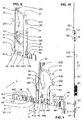
- figure 1 shows a sliding door system 1 with two sliding leaves 4, 6, two side parts 2, 3 and a skylight 5 extending over the entire width of the sliding door system 1.
- Side parts 2, 3 and skylights 5 can in principle be omitted;
- only a single sliding leaf 4.6 can be provided.
- the two sliding leaves 4, 6 each have a vertical closing edge 4a, 6a in the closing direction and a horizontal closing edge 4b, 6b at the bottom.
- the vertical closing edges 4a, 6a form a main closing edge H in mutual contact in the closed position.
- the closing direction S for the in 1 Sliding leaf 4 shown on the right runs horizontally from right to left.
- the closing direction S for the in 1 Sliding leaf 6 shown on the left runs horizontally from left to right.
- the two sliding leaves 4, 6 each form a horizontal secondary closing edge N1, N2 with their respective lower horizontal closing edges 4b, 6b and a floor guide device 150, 160.
- the vertical secondary closing edges 4b, 6b are formed on the respective vertical edges of the respective sliding leaves 4, 6 opposite the said vertical closing edges 4a, 6a.
- the first sliding sash 4 (on the right in 1 ) assigned elements are marked, where necessary, with the term "first" that the second sliding sash 6 (on the left in 1 ) assigned elements are each marked with the term "second".
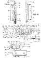
- FIG. 2 shows a cut-open floor guide unit 150, 160.
- the floor guide unit 150, 160 is permanently sunk or embedded in the floor, thereby providing increased stability and, as a result, improved protection against burglary.
- the lower end section of the sliding leaf 4, 6 can be seen in the upper area. From this lower end portion of the sliding leaf 4, 6, a bottom bar 11, 13 protrudes downward.
- a sliding element 110, 130 is slipped over the bottom bar 11, 13 and is preferably fastened there.
- the bottom bar 11, 13 with sliders 110, 130 protrudes into a guide chamber 151 (see Fig. 2 ).
- the guide chamber 151 is formed by a floor guide profile 150 of the floor guide unit 150, 160.
- the floor guide profile 150 provides the guide chamber wall 152 . How out 2 As can be seen, the bottom bar 11, 13 contacts the guide chamber wall 152 via the slider 110, 130. The bottom bar 11, 13 with the slider 110, 130 protrudes 30 millimeters into the guide chamber 151, which is 40 millimeters deep. In this way, the sliding leaf 4, 6 is guided in the guide chamber 151 along the closing movement in the closing direction S.
- the closing direction S is in 2 perpendicular to the drawing plane.
- the floor guide profile 150 is let into a floor connection profile 160 .
- the floor guide profile 150 is in turn embedded in the floor and provides the bearing surfaces 153, on which bearing elements 161 of the floor connection profile 160 rest.
- the floor guide profile 150 and the floor connection profile 160 can be attached to one another and to the floor, for example screwed. Furthermore shows 2 the first and the second horizontal secondary closing edge N1, N2.
- FIG 3 shows the second sliding leaf 6 with parts of the first sliding leaf 4 in a perspective view from below. Only a vertical profile 40 of the first sliding leaf 4 is shown. This vertical profile 40 provides the first vertical closing edge 4a with a groove 41 . A second vertical profile 60 of the second sliding leaf 6 provides the second vertical closing edge 6a with a ridge 61 . Both the comb-like elevation 61 and the groove 41 run along the respective vertical profiles 40, 60 over the entire length of the vertical profiles 40,60.
- a door panel 67 for example made of glass, of the second sliding leaf 6 can also be seen on the left.
- a vertical closing profile 68 is provided at the left end of the second sliding leaf 6 opposite the second vertical profile 60 .
- the vertical end profile 68 and the second vertical profile 60 are connected via a horizontal profile 69 .
- the first sliding leaf 4 also has a vertical end profile and a horizontal profile in a similar way, which are shown in 3 are not shown.
- the vertical profiles 40, 60 are preferably made of metal or plastic or a combination of these materials or other dimensionally stable materials known to those skilled in the art, are therefore extremely dimensionally stable and burglar-resistant, and extend from the floor to the lower end of the skylight 5.
- the walls of the vertical profiles 40 , 60 are 2 to 5 millimeters thick.
- the vertical profiles 40, 60 are essentially 100 millimeters wide, having a material thickness in the passage direction D of 25 to 100 millimeters, in particular 35 millimeters.
- the horizontal profile 69 and the vertical end profile 68 have the same material thickness in the passage direction D.
- the height of the horizontal profile 69 is 50-120 millimeters, its length in the closing direction S up to 200 centimeters.
- the vertical closing profile 68 also extends from the floor to the lower end of the skylight 5 and has a width in the closing direction S of essentially 100 millimeters.
- the second horizontal closing edge 6b is provided by the lower ends of the vertical profile 60, the vertical end profile 68 and the horizontal profile 69.
- a recess 65 is arranged on the second horizontal closing edge 6b (which is basically a mirror image of the horizontal closing edge 4b or the main closing edge H). Furthermore, in 3 the floor bars 11, 13 can be seen, which engage in the recess 65 and in the vertical profile 60 and the vertical end profile 68 (see below and 4 ).
- the first vertical profile 40 and the vertical end profile assigned to it also each have a bottom bar, which for the sake of clarity is shown in 3 are not shown; What follows for the bottom bars 11, 13 of the second sliding sash 6 also applies accordingly to the bottom bars of the first sliding sash 4.
- the bottom bar in the first vertical profile 40 is shaped and attached with respect to the main closing edge H essentially mirror-symmetrically to the bottom bar 11 in the second vertical profile 60 .
- the two bottom bars in the vertical profiles 40, 60 are then directed towards one another with respective projections 116. These projections complete the construction below the main closing edge H in the closing direction S.
- respective first horizontal legs 111, 131 and second vertical legs 112, 132 of the L-shaped bottom bar 11, 13 are shown. These first legs 111 and 131 are fitted in the recess 65 and are used to fasten the floor bars 11, 13 in the sliding sash 6.
- figure 4 shows an exploded view of the second sliding leaf 6 with floor bars 11, 13.
- the second vertical profile 60 is shown with the vertical chamber 62 running vertically upwards.
- the vertical closing profile 68 with a further, vertically running chamber 66 is shown on the left-hand side.
- a first bottom bar 11 is shown on the right.
- the L-shaped floor bar 11 has an engagement element 118 with a slide element 110.
- the engagement element 118 with slide 110 can be inserted into the guide chamber 151 of the floor guide profile 151 (see 2 ).
- the first leg 111 of the bottom bar 11 extends horizontally beyond the engagement element 118 and is intended for mounting the bottom bar 11 in the recess 65 .
- the second leg 112 of the bottom bar 11 runs in the vertical direction V and can be inserted laterally with a precise fit into the vertical chamber 62 of the vertical profile 60 .
- the two legs 111, 112 extend approximately as far beyond the engagement element 118 as the latter is long.
- the bottom bar 11 has screws 115 by means of which the bottom bar 11 inserted into the sliding leaf 6 can be securely fixed in the vertical profile 60 .
- the engagement element 118 extends in the closing direction S over a length of approximately the width of the vertical profile 60 over the engagement element 118.
- the engagement element 118 is guided over the projection 116 (a section of the engagement element 118) to below the ridge 61.
- Bottom bars which are arranged opposite each other over the main closing edge H, close the gap below the main closing edge H by means of these projections 116.
- the screws 114 are provided on the first leg 111, by means of which the plate 113 is attached to the bottom bar 11 is attached. This plate 113 is then inserted to the depth of the groove 65 and ensures that the floor bar 11 is held in the correct vertical position.
- the second floor bar 13 is shown, which is designed to be essentially mirror-symmetrical to the first floor bar 11 .
- this floor bar 13 also has an L-shape with an engagement element 138, with a first leg 131 which runs horizontally over the engagement element 138 and with a second leg 132 which protrudes vertically over the engagement element 138.
- a plate 133 is fastened to the first leg 131 by means of screws 134 .
- the plate 133 like the plate 113, is placed in the depth of the groove-like recess 65.
- the second, vertical leg 132 can be inserted into the vertically running chamber 66 of the vertical connection profile 68 and can be fixed there.
- the legs 112 and 132 are each 50 millimeters to 200 millimeters long, e.g. 10 millimeters wide (in the closing direction S) and e.g. 30 millimeters to 40 millimeters thick (in the passage direction D), the latter depending on the corresponding thickness of the vertical profiles 40, 60 depends.
- This massive construction inserts the legs 112 and 132 deeply into the vertical profiles 40, 60 and the corresponding vertical end profiles 68.
- This configuration stabilizes the frame 68 , 69 , 60 of the sliding leaf 4 , 6 and ensures that the sliding leaf 4 , 6 is guided in the floor guide profile 150 by means of the engagement elements 118 , 138 . In addition, it is efficiently prevented that the sliding sash 4, 6 is pushed or pulled transversely to the running direction from the intended position.
- the second vertical closing edge 6a of the vertical profile 60 is shown at the top right.
- the ridge 61 which extends in the vertical direction V, is clearly visible.
- This elevation 61 is introduced as a tongue according to the tongue and groove principle in the groove 41 of the vertical profile 40 and represents, so to speak, a counter sealing profile to the groove 41.
- the locking device 20 consists of a U-forend plate 22 which is inserted or pushed into the groove 41 of the vertical profile 40 and which (with the outside 222) provides the rear limitation in the depth of the groove 41.
- FIG 5 the second sliding leaf 6 with the closing device 20 is shown.
- the vertical profile 60 with the ridge 61 can be seen and it can be seen that the ridge 61 extends from the bottom all the way up.
- the forend plate 22 is shown in a position in which it comes to rest when the vertical profiles 40, 60 engage in one another, ie when the vertical closing edges 4a, 6a are in mutual contact in the closed position.
- the U-forend plate 22 is in the vertical profile 40, which is figure 5 is not shown housed.
- Swivel lock boxes 21, 23, 26, 27, sliding blocks 220 and the motor 50 are attached to an inner side 221 of the forend plate 22 (see also below and 10 ). The elements just mentioned are thus accommodated in the vertical profile 40 .
- the swivel lock boxes 21, 23, 26, 27 are known, for example, from the prior art and surround a swivel lock 211, 231, 261, 271, which can be swiveled in a forward swivel movement, in this case in the direction of the vertical profile 60.
- the motor 50 is supplied and controlled via a control and/or feed line 51 which is connected to the motor 50 via a plug 52 .
- figure 6 shows an enlarged section figure 5 the vertical profile 60 has been omitted for clarity.
- the U-forend plate 22 can be seen again, on which the sliding blocks 220 and the swivel bolt boxes 21, 23 are visible.
- figure 7 shows a similar situation, looking at the outer surface 222 of the U-forend plate 22 from the left.
- swivel bolt boxes 21 and 23 are also referred to here. What was mentioned should then also apply to the other swivel bolt boxes 26 and 27, where appropriate.
- a pivot bolt 211, 231 is fitted in each pivot bolt box 21, 23. This pivoting bolt 211, 231 can be guided in a pivoting movement out of the pivoting bolt box 21, 23 through a recess 224, 223 through the U-shaped forend plate 22 (by means of a drive rod 55, see below).
- the extended swivel bolts 211, 231 protrude beyond the U-shaped forend plate 22 on its outside 222 and engage in a locking bar 29 arranged in the comb 61 opposite the forend plate.
- the bolts 211, 231 engage behind the locking bar 29 in each case, so that a form fit is realized in a direction parallel to the closing direction S.
- Respective engagement recesses 291, 292 are attached in the locking strip 29 for this engagement.
- Preferably one recess 291,292 is provided per latch 211,231. Since the locking bar 29 is mounted in a vertical chamber 63 in the comb 61 (see below), the comb 61 has openings at the locations of the recesses 291, 292 of the locking bar 29, so that the bolts 211, 231 can be inserted into the comb 61 and the one behind it Closing bar 29 can intervene.
- the pivot bolt 211, 231 is thus pivoted through the recess 291, 292 behind the closing strip 29.
- the hook-like design of the pivot bolt 211, 231 enables the pivot bolt 211, 213 to engage behind the locking bar 29.
- the locking strip 29 is firmly attached to or on the second vertical profile 60 (in the comb 61).
- the vertical profiles 40, 60 can thus be locked against one another by means of the swivel bolts 211, 231 and the closing strip 29, so that an opening movement (in particular along the closing movement) of the sliding leaves 4, 6 is prevented.
- a mushroom pin 212, 232 is attached in each case.
- This mushroom pin 212, 232 protrudes in each case (up to about 20 millimeters) towards the depth of the vertical profile 40.
- the retaining plate 24 is shown, which provides recesses 241, 243.
- the mushroom pins 212, 232 and the retaining plate 24 now form a bayonet catch via these recesses 241, 243 with a positive fit parallel to the S direction.
- the bayonet lock is useful for efficient assembly.
- the retaining plate 24 protrudes beyond the swivel bolt boxes on the broad side, as does the U-forend plate 22, which can be seen from the figures mentioned.
- figure 8 shows the U-forend plate 22 with the pivot bolt boxes 21, 23, which protrude backwards on the inside 221 of the U-forend plate 22 into the depth of the chamber 44a, 44b.
- the retaining plate 24 is also shown.
- the vertical profile 40 can also be seen. It can be seen that the U forend plate 22 can be pushed into the profile 40 .
- the retaining strip 24 can be inserted vertically into the profile 40.
- the vertical profile 40 has corresponding recesses in the vertical chamber 42 (for example in the partition wall 421, see below).
- the vertical profile 40 therefore has the vertical chamber 42 to accommodate the elements mentioned.
- This vertical chamber 42 closes in 8 right to the inside 221 of the U-forend plate 22, wherein the groove 41 extends from the other side, the outside 222 of the U-forend plate 22 to the left.
- the groove 41 is delimited by an outer flank 41a and an inner flank 41b and the outside of the U-shaped forend plate.
- the expression “outer” or “inner” refers to the respective arrangement of the flank 41a, 41b with respect to the outside or the inside of the building opening, which can be closed by the system 1.
- flanks 41a and 41b are in 13 evident. These flanks 41a and 41b have free ends 41f and 41g, respectively. At the free ends 41f, 41g, the flanks 41a, 41b are 4 millimeters thick or thick (in passage direction D), this thickness or material thickness increasing towards the rear (ie towards the forend plate 22) by 25% to 30%. The corresponding edges can each be rounded.
- flanks 41a, 41b overlap in such a way that unauthorized access via the main closing edge H (i.e. the vertical closing edges 4a, 6a) to parts of the closing device 20 (e.g. by means of a lever tool such as a "cow's foot") is made more difficult, which has a burglary-resistant effect.
- a vertical gap 41e (see Fig. 3 ), which exists between the free ends 41f, 41g of the flanks 41a, 41b and the vertical profile 60 in the closing direction S (see 13 ) should therefore be minimal, here (with vertical profiles 35 millimeters thick in the D direction) the gap is then less than 1 millimeter wide.
- flanks 41a, 41b should be stable and thick enough to withstand a violent attempted break-in for as long as possible.
- the crest 61 is preferably formed on the vertical profile 60 in such a way that the flanks 41a, 41b engage in the vertical profile 60 to the side of the crest 61 (i.e. in direction D), so that against the outside (and preferably also the inside) a flush surface 46 (see 3 ) is formed. This minimizes the number of possible points of attack for lever tools or striking tools.
- the groove 41 is delimited by the outside 222 of the forend plate 22 at a depth of 11.5 millimeters.
- the chambers 42 adjoin the groove 41 on the inside 221 of the 1 to 3 millimeter thick U-shaped forend plate 22 opposite the outside 222 and extends both in the vertical direction V and 20 to 100 millimeters in depth, i.e. in the opposite direction the closing direction S of the closing leaf 4, in the vertical profile 40.
- both vertical profiles 40 and 60 are shown. It can be seen that the vertical profile 60 also has a vertical chamber 62 . As in 9 can also be seen, a partition 621, which runs in the vertical direction, divides the vertical chamber 62 into two vertical partial chambers 63 and 64 (this partition 621 corresponds to the partition 421 in the first vertical profile 40, see below.).
- the first sub-chamber 63 extends from the rear into the ridge 61.
- the second sub-chamber 64 is lower (i.e. further back, opposite to the closing direction S) in the vertical profile 60 than the first sub-chamber 63 and has vertical webs 642 attached laterally in the center with respect to the closing direction , which extend into the chamber 62 from the edge.
- the first and second partial chambers 63, 64 run all the way down in the vertical profile 60 and are open at the bottom.
- the bottom bar 11 is inserted into the vertical profile 60 from below.
- the vertically standing second leg 112 is introduced into the first sub-chamber 63 and rests against the partition wall 621 at the rear. This is also in 13 recognizable.
- figure 13 shows a top view of interlocking vertical profiles 40, 60 with elements of the locking device 20 and elements of the bottom bar 11. It can be seen that the vertically standing second leg 112 is pushed into the chamber 63 close to the partition wall 621.
- the locking bar 29 is also inserted into the partial chamber 63 .
- the locking bar 29 is pushed into the front area of the sub-chamber 63 and contacts the comb 61 from behind (see also 13 ).
- the comb 61 has passage openings from the outside through the recesses 291, 292 into the partial chamber 63 at the appropriate points.
- a sealing profile 8 is provided near the end regions of the flanks 41a, 41b of the groove 41, which laterally enclose the elevation 61.
- This sealing profile 8 is attached to the end of the comb 61 on the vertical profile side and makes sealing contact with the free ends of the flanks 41a, 41b when the sliding leaves 40, 60 are closed. It's further into the figs 9 and 13 recognizable that the closing strip 29 is inserted into the foremost section of the sub-chamber 63, this foremost part of the sub-chamber 63 encompassing the closing strip 29 to the rear, so that the closing strip 29 is positively locked in the closing direction S.
- the vertical profile 40 On the right in 9 the vertical profile 40 is shown.
- the vertical chamber 42 can be seen, which is divided into two vertical chambers 43 and 44a, 44b by a partition wall 421.
- the vertical sub-chamber 44a, 44b has a second vertical web 442 in the center with respect to the closing direction S, and a first vertical web 441 behind the second vertical web 442.
- the second vertical profile 60 has a corresponding vertical web 641.
- the vertical webs 441, 442, 641, 642 run parallel to the groove 41 and the ridge 61.
- the holding strip 24 is inserted into the vertical partial chamber 44a, 44b, specifically between the first vertical web 441 and the second vertical web 442 and is thus parallel in one direction found positively to the closing direction S.
- the retaining strip 24 spans the vertical profile 40 in the entire clear width (in direction D) and thus divides the sub-chamber 44a, 44b into a front sub-chamber 44a and a rear sub-chamber 44b (see also Fig.13 ).
- retaining strip 24 In order to fix the retaining strip 24 vertically, screws 293 running essentially horizontally penetrate the retaining strip 24 from the front to the rear, with the screws 293 protruding backwards over the retaining strip 24 .
- a rear wall of the vertical partial chamber 44b can then have threaded holes (or provide corresponding means) in which the holding strip 24 is fixed by means of screws 293.
- the retaining strip 24 can also be fixed vertically in another way that is obvious to a person skilled in the art.
- Several holding strips 24 (and/or closing strips 29) can also be provided in the vertical profiles 40 (or in the profile 60), depending on the number of swivel bolt boxes.
- figure 13 shows that the U-forend plate 22, which is inserted from the front into the groove 41 and limits the depth of the groove 41 to the rear, and the sliding blocks 220, which are inserted in a form-fitting manner into the sub-chamber 43 and can be moved vertically, interact in a form-fitting manner.
- the sliding blocks 220 are fixed by screws, which run from an outside 222 through the U-forend plate 22 into the sliding blocks 220.
- the sliding blocks 220 are inserted in the vertical sub-chamber 43 and lie in the closing direction S from behind on a vertically running web 41c of the vertical profile 40 .
- the U-forend plate 22 rests on these webs 41c from the front.
- the U-forend plate 22 thus holds the two flanks 41a, 41b together in a form-fitting manner with respect to the passage direction D; In other words, the U-forend plate 22 surrounds the two vertical webs 41c. This increases the stability of the flanks 41a, 41b and counteracts the flanks from bending open or breaking up from the outside (with respect to the groove 41). It is therefore also preferred that the forend plate extends over the entire length of the groove 41 and secures the engagement of the groove 41 and the ridge 61 . In this case, a form fit is realized in a direction parallel to the closing direction S.
- FIG 10 shows the U-forend plate 22 with four mounted swivel bolt boxes 21, 23, 26, 27 (an upper pair 26, 27 and a lower pair 21, 23).
- locking pins 25 are attached on the outside 222 of the U-forend plate 22 .
- Such a locking pin 25 is also in the lower part of 7 recognizable.
- these pins 25 also called centering pins 25
- pivoting bolt boxes 21, 23 are arranged such that the lower pivoting bolt 211, 231 of the lower pivoting bolt boxes 21, 23 are guided in a pivoting movement, which leads from bottom to top.
- the upper pivoting bolt boxes 26, 27 are reversed (that is to say in opposite directions) so that their pivoting bolts 261, 271 perform a pivoting movement pointing from top to bottom.
- This mirror-symmetrical arrangement prevents the locked sliding leaves 4 , 6 from being able to be moved upwards or downwards and thus the swivel bolts 211 , 231 , 261 , 271 being simply lifted out of the corresponding recesses in the locking bar 29 .
- the drive rod 55 which in the figs 5, 6 , 8, 9 is recognizable.
- This connecting rod 55 is linearly movable, with its linear movement being transformed in the pivoting bolt boxes 21, 23, 26, 27 in such a way that the pivoting bolts 211, 231, 261, 271 carry out their corresponding pivoting movements.
- the motor 50 can be provided to actuate this connecting rod 55 (see e.g. figure 5 ) or the connecting rod 55 can be operated manually. Instead of the motor, it is also possible, for example, to use an electromagnet or other electrically operated elements to actuate the drive rod 55 . So it is both a version for automatic and one for manual operation possible.
- a middle lock 70 which serves as the main lock 70 .
- This main lock 70 has a lock cylinder 71 in which, for example, a key can be inserted. If the key fits, the drive rod 55 can be actuated either manually or automatically via the motor 50 by means of a corresponding rotational movement of the key via a known locking mechanism.
- anti-drill plates 73, 74 In order to make unauthorized access to the drive rod 55 and the main lock 70 from the outside even more difficult, anti-drill plates 73, 74, as in 11 visible, protectively attached. These drilling protection plates 73, 74 block access to the drive rod 55 and are preferably made of steel and are several millimeters thick.
- figure 12 shows the center lock 70 in a view from the front and its arrangement relative to the U-forend plate 22. Part of the lock cylinder 71 and the cover 72 can be seen from the front.
- figure 14 shows the object of in a view 12 from underneath. It shows the center lock 70 with the lock cylinder 71 and the cover 72 as well as the U-forend plate 22 with mounted swivel bolt box 21 and to the right adjoining mushroom pin 212, which engages through a corresponding recess in the holding strip 24 and passes through it.
- figure 15 shows a perspective side view from the front bottom left of the second sliding leaf 6 with the vertical end profile 68 and the door panel 67.
- figure 16 shows an enlarged section of the illustration 15 from a more frontal perspective. Also note this 17 , which the subject after 15 shows from the side. For the sake of clarity, the hatching of the section has been 17 each omitted.
- an upper horizontal profile 33 is provided in the upper end area of the sliding leaf 6, which extends between the second vertical profile 60 and the vertical end profile 68 (parallel to the lower horizontal profile 69 at the upper end of the door panel). Also in 17 below is the door leaf 6 of the Sliding leaf 6 can be seen, to which the upper horizontal profile 33 connects to the top. The upper horizontal profile 33 is firmly connected to the sliding leaf 6 in question.
- the horizontal profiles 33, 69, the second vertical profile 60 and the vertical end profile 68 thus form a peripheral frame in which the door panel 67 of the wing 6 is provided.
- the details described here can also apply to the first sliding leaf 4, which (up to about a mirror-image design) depending on the embodiment can differ structurally from the second sliding leaf 6, for example essentially only in the area of the vertical profile 40.
- the sliding panel 6 is fastened to two carriages 32 via the upper horizontal profile 33, which essentially extends horizontally between the vertical end profile 68 and the second vertical profile 60.
- a secure screw connection screws 313 is preferred for this purpose.
- a stationary fixed running profile 31 with a rail profile 30 is provided for the suspension of the sliding doors 4, 6 (see in particular figs 15 , 17 ), which provides means for suspension and guidance of the carriage 32.
- the running profile 31 provides a leg 310 running horizontally along the closing movement of the sliding leaf 6 .
- the leg 310 has a free-standing end on the upper side of which a rail 311 for the carriages 32 is provided.
- the carriages 32 have running wheels 321 which provide a concave running surface. If the carriage 32 is placed on the rail 311, this engages in the concave running surfaces of the running wheels 321 according to its convex cross-sectional shape. There are 2 or 3 such wheels 321 provided per carriage 32 here.
- the rail 311 can also be concave and the respective running surface of the running wheel 321 can be convex in shape, which enables a similar intervention, which has a laterally guiding effect. Thanks to this configuration, the sliding leaf 6 can be pivoted perpendicularly to the closing movement over a limited angular range without the forces acting thereby causing damage to the rail 311, rail profile 30 and/or running wheels 321.
- a first anti-lift device 322 is provided in the form of a metal plate 322, which protrudes upwards from the carriage body of the carriage 32 and the mentioned lifting movement of the leaf 6 upwards (see Fig . 17 ) limited by the fact that the plate 322 is present at the top of the running profile 31, forming a flat contact. Contact surfaces of this contact forming the stop are preferably rough, so that it is difficult or impossible to move the lifted sliding leaf 6 pressing the plate 322 against the running profile 31 along the closing movement into the open state.
- This plate 322 may be vertically offset from a pivot point (defined by rail 311) (see Fig. 17 , plate 322 is offset to the right). However, it is also conceivable that the plate 322 is attached in a different way (and thus contacts another preferably stationary element); it is important that the plate 322 supports the lifting movement of the carriage 32 (in 17 to the right and up) and the wing 6 limited. Each carriage 32 can provide at least one stop 322 .
- the carriages 32 make rolling contact with the running profile 31 via the rail 311 which is provided on a leg 310 of the running profile 31 which protrudes horizontally from the running profile 31 and runs parallel to the closing direction S.
- the carriage 32 then extends with the carriage body in front of the leg 310, as described above, at least partially upwards and also over a wing adaptation angle 34 to below the leg 310 (see Fig. Figures 15-17 ).
- a plate-like second anti-lever device 324 is attached to the bottom of the leg 310 in the area above the adaptation angle 34 of each carriage 32 in the closed position.
- the second anti-lift device 324 extends downwards under the rail 311 and provides a stop for the respective adaptation bracket 34, which allows the sliding sash 6 to pivot to both sides in the passage direction D (in 17 left and right) limited.
- the second anti-lift device 324 (as in 17 indicated) composed of several plates, preferably made of metal or plastic. These plates can be 3 to 15 millimeters thick, for example.
- the overhang of the anti-leverage device 324 can be adjusted downwards over the leg 310 . With which the distance between the locking screws 313 or adaptation bracket 34 and the second anti-lever device 324 can be adjusted.
- the essentially U-shaped adaptation bracket 34 encompasses the second anti-leverage device 324 at the bottom and is located behind the second anti-leverage device 324 (on the left in 17 ) via a section 341 back up.
- the section 324 of the adaptation bracket 34 strikes the second anti-lever device 324 on the left.
- the adaptation bracket 34 swings in the right-hand area of the second anti-lift device 324 (see Fig 17 ) and/or the section 341 strikes the profile 30 (or an associated screw) on the left.
- the locking screws 313 limit these pivoting movements to the left and to the right or support or secure the limiting effect.
- the locking screws 313 also hit the second anti-leverage device 324 and thus support the effect of the above-mentioned first anti-leverage device 322.
- an alternative geometry is chosen in a different way that is obvious to a person skilled in the art.
- the first and second anti-lever devices 322, 324 effectively make it more difficult to lever out the sliding sash, in particular in conjunction with the floor latches described above, which are guided in the floor guide 150, 160 along the closing movement.
Landscapes
- Engineering & Computer Science (AREA)
- Mechanical Engineering (AREA)
- Civil Engineering (AREA)
- Structural Engineering (AREA)
- Specific Sealing Or Ventilating Devices For Doors And Windows (AREA)
Description
Die vorliegende Erfindung betrifft eine Schiebeflügelanlage gemäss dem Oberbegriff des Anspruchs 1.The present invention relates to a sliding leaf system according to the preamble of
Schiebeflügelanlagen, insbesondere Schiebetüranlagen werden verbreitet eingesetzt, bevorzugt an Orten, wo Gebäudeöffnungen häufig von Personen durchschritten werden. Eine Schiebeflügelanlage vermag, eine grosse Gebäudeöffnung, durch welche eine oder mehrere Personen gleichzeitig durchtreten können, schnell und zuverlässig zu bedienen. Es ist ein grundlegendes Bedürfnis, dass diese Schiebeflügelanlagen auch unbefugten Zutritt verhindern, also bspw. über Nacht abschliessbar sind. Die Hauptschliesskante dieser Anlagen stellt bei der Einbruchsicherheit einen Schwachpunkt der Schliessanlage dar.Sliding leaf systems, in particular sliding door systems, are widely used, preferably in places where building openings are frequently walked through by people. A sliding sash system is able to quickly and reliably operate a large building opening through which one or more people can pass at the same time. It is a fundamental requirement that these sliding sash systems also prevent unauthorized access, i.e. that they can be locked overnight, for example. The main closing edge of these systems represents a weak point of the locking system in terms of burglary security.
Die
Dichtungselemente zur Dichtung der Hauptschliesskante bei Schiebetüranlagen sind bspw. aus den Dokumenten
Aus der
Es ist daher eine Aufgabe der vorliegenden Erfindung, eine Schiebeflügelanlage, insbesondere eine Schiebetür- oder Schiebefensteranlage oder eine Schliesskantenkonstruktion bereitzustellen, welche erhöhte mechanische Stabilität zur besseren Einbruchsicherung gewährt.It is therefore an object of the present invention to provide a sliding leaf system, in particular a sliding door or sliding window system or a closing edge construction, which provides increased mechanical stability for better protection against burglary.
Diese und weitere Aufgaben werden durch eine Schiebeflügelanlage, insbesondere eine automatische Schiebetüranlage, umfassend mindestens einen Schiebeflügel, wobei der Schiebeflügel entlang einer Schliessbewegung eine Gebäudeöffnung in einer Durchgangsrichtung verschliessend in einer Bodenführungseinrichtung verschiebbar ist und in einer im Wesentlichen horizontalen Schliessrichtung eine erste Vertikalschliesskante bereitstellt, und die Schiebeflügelanlage eine zweite Vertikalschliesskante bereitstellt, wobei die erste und die zweite Vertikalschliesskante gegenseitig in schliessende Anlage bringbar sind, und wobei der Schiebeflügel eine Horizontalschliesskante bereitstellt, welche mit der Bodenführungseinrichtung eine sich entlang der Schliessrichtung erstreckende horizontale Nebenschliesskante bildet, dadurch gelöst,
dass an mindestens einer dieser Vertikalschliesskanten zumindest abschnittsweise mindestens eine sich im Wesentlichen in Vertikalrichtung erstreckende und in Schliessrichtung frei abstehende, aus Metall oder Kunststoff oder deren Kombination bestehende, formstabile und zu einer Aussenseite der Gebäudeöffnung hin versetzt auf der entsprechenden Vertikalschliesskanten angebrachte, äussere Flanke bereitgestellt ist,
dass jeweils gegenüberliegend dieser äusseren Flanke an der anderen Vertikalschliesskante ein mit dieser äusseren Flanke korrespondierender, sich im Wesentlichen in Vertikalrichtung erstreckender und in Schliessrichtung abragender, aus Metall oder Kunststoff oder deren Kombination bestehender, formstabiler Kamm angeordnet ist, wobei dieser Kamm bezüglich der äusseren Flanke seitlich zu einer Innenseite der Gebäudeöffnung hin versetzt verläuft und durch die Schliessbewegung (unter Formschluss in Durchgangsrichtung) mit einer zur Innenseite der Gebäudeöffnung hin gerichteten Innenseite der Flanke in Eingriff bringbar ist,
und dass eine an diesen Vertikalschliesskanten angeordnete Schliesseinrichtung mit mindestens einem Verriegelungspunkt zur Feststellung des Schiebeflügels bei gegenseitig in schliessender Anlage befindlicher erster und zweiter Vertikalschliesskante bereitgestellt ist, wobei dieser Verriegelungspunkt kammseitig bereitgestellt ist, sodass die äussere Flanke den Verriegelungspunkt zur Aussenseite der Gebäudeöffnung hin überdeckt.These and other objects are achieved by a sliding leaf system, in particular an automatic sliding door system, comprising at least one sliding leaf, the sliding leaf being displaceable in a floor guide device along a closing movement, closing a building opening in a passage direction, and providing a first vertical closing edge in a substantially horizontal closing direction, and the Sliding leaf system provides a second vertical closing edge, wherein the first and the second vertical closing edge can be brought into mutually closing contact, and wherein the sliding leaf provides a horizontal closing edge which, together with the floor guide device, forms a horizontal secondary closing edge extending along the closing direction, thereby solved,
that on at least one of these vertical closing edges at least one outer flank, which extends essentially in the vertical direction and protrudes freely in the closing direction, is made of metal or plastic or a combination thereof, is dimensionally stable and is attached to the corresponding vertical closing edge offset towards an outside of the building opening is provided, at least in sections ,
that in each case opposite this outer flank on the other vertical closing edge there is a dimensionally stable comb which corresponds to this outer flank, extends essentially in the vertical direction and protrudes in the closing direction and consists of metal or plastic or a combination thereof, with this comb being lateral with respect to the outer flank runs offset towards an inside of the building opening and can be brought into engagement with an inside of the flank directed towards the inside of the building opening by the closing movement (with positive locking in the direction of passage),
and that a locking device arranged on these vertical closing edges is provided with at least one locking point for fixing the sliding sash when the first and second vertical closing edges are in mutually closing contact, with this locking point being provided on the comb side so that the outer flank covers the locking point on the outside of the building opening.
Die äussere Flanke bildet mit der Vertikalschliesskante, an welcher sie angebracht ist, eine erste Stufe oder einen ersten Versatz, wobei der Kamm mit der anderen Vertikalschliesskante eine zweite Stufe oder einen zweiten Versatz bildet. Die erste Stufe und die zweite Stufe sind hierbei gegengleich ausgebildet, sodass sie in Schliessrichtung ineinandergreifen können. Die erste und die zweite Stufe können auch mehrstufig ausgestaltet sein. Hierbei übergreift die äussere Flanke den Kamm zumindest teilweise, vorzugsweise im Wesentlichen ganz, sodass der Kamm gegen die Aussenseite der Gebäudeöffnung hin von der äusseren Flanke überdeckt ist. Damit ist ein freies Ende des Kamms von der Aussenseite her bei sich in schliessender Anlage befindlichen Vertikalschliesskanten nicht zugänglich.The outer flank forms a first step or offset with the vertical closing edge to which it is attached, the crest forming a second step or offset with the other vertical closing edge offset forms. The first stage and the second stage are of opposite design here, so that they can engage in one another in the closing direction. The first and the second stage can also be multi-stage. In this case, the outer flank overlaps the ridge at least partially, preferably essentially completely, so that the ridge is covered by the outer flank towards the outside of the building opening. A free end of the comb is therefore not accessible from the outside when the vertical closing edges are in closing contact.
Einer Weiterbildung der Schiebeflügelanlage ist dadurch gekennzeichnet, dass an der die äussere Flanke bereitstellenden Vertikalschliesskante eine weitere, zur äusseren Flanke im Wesentlichen parallel verlaufende und in Durchgangsrichtung von der äusseren Flanke gegen die Innenseite der Gebäudeöffnung hin versetzt beabstandet angebrachte innere Flanke bereitgestellt ist. Auch diese innere Flanke ragt gegen den Kamm, wobei die innere Flanke im Wesentlichen spiegelsymmetrisch zur äusseren Flanke bezüglich einer Spiegelebene ist, wobei diese Spiegelebene eine vertikalen Ebene parallel zur Gebäudeöffnung durch die Flügelmitte ist.A further development of the sliding sash system is characterized in that on the vertical closing edge providing the outer flank there is a further inner flank which runs essentially parallel to the outer flank and is offset in the passage direction from the outer flank towards the inside of the building opening. This inner flank also protrudes towards the ridge, the inner flank being essentially mirror-symmetrical to the outer flank with respect to a mirror plane, this mirror plane being a vertical plane parallel to the building opening through the center of the wing.
Zwischen der äusseren Flanke und der inneren Flanke ist eine im Wesentlichen vertikal verlaufende Nut gebildet, welche in Schliessrichtung offen ist und in einer Richtung parallel zur Durchgangsrichtung durch die äussere und die innere Flanke begrenzt ist. Die Flanken stehen hierbei vorzugsweise im Wesentlichen gleichweit in Schliessrichtung über die Vertikalschliesskante ab. Die so gebildete Nut und der besagte Kamm sind hierbei derart ausgestaltet, dass sie durch die Schliessbewegung in gegenseitigen Eingriff bringbar sind. Es ist bevorzugt, dass dieser Eingriff sich abschnittsweise zusammengenommen über mindestens eine Hälfte der Längserstreckung der Vertikalschliesskanten, vorzugsweise über die gesamte Längserstreckung der Vertikalschliesskanten erstreckt. Weiter ist bevorzugt, dass sich dieser Kamm in Durchgangsrichtung im Wesentlichen über die lichte Weite der Nut und in Vertikalrichtung im Wesentlichen über eine Länge der Nut erstreckt. Vorteilhafterweise greift der Kamm beim Eingriff in die Nut bis im Wesentlichen auf eine Tiefe der Nut ein. So ist insbesondere die äussere Flanke vom Kamm gestützt und kann Druck senkrecht auf die Flanke (von aussen) gut standhalten.A substantially vertical groove is formed between the outer flank and the inner flank, which is open in the closing direction and is delimited in a direction parallel to the direction of passage through the outer and inner flanks. In this case, the flanks preferably protrude substantially the same distance in the closing direction over the vertical closing edge. The groove formed in this way and said ridge are designed in such a way that they can be brought into mutual engagement by the closing movement. It is preferred that this engagement, taken together in sections, extends over at least one half of the longitudinal extent of the vertical closing edges, preferably over the entire longitudinal extent of the vertical closing edges. It is further preferred that this ridge extends in the passage direction essentially over the clear width of the groove and in the vertical direction essentially over a length of the groove. Advantageously, when engaged in the groove, the ridge engages substantially to a depth of the groove. In particular, the outer flank is supported by the crest and can withstand pressure perpendicular to the flank (from the outside).
Erfindungsgemäß steht oder stehen die Flanke(n) frei über 10 Millimeter bis 30 Millimeter in Schliessrichtung über die Vertikalschliesskante ab und weist oder weisen dabei eine Materialstärke in Durchgangsrichtung auf welche sich vorzugsweise gegen ein freies Ende der Flanke(n) hin verjüngt und jeweils mindestens 2 Millimeter bis 10 Millimeter, vorzugsweise mehr als 3 Millimeter, insbesondere 4 Millimeter oder mehr beträgt. Der Kamm kann dann an seinem freien Ende in Durchgangsrichtung bspw. 20 bis 90 Millimeter breit sein.According to the invention, the flank(s) protrudes more than 10 millimeters to 30 millimeters in the closing direction beyond the vertical closing edge and has or have a material thickness in the direction of passage which preferably tapers towards a free end of the flank(s) and in each case at least 2 Millimeters to 10 millimeters, preferably more than 3 millimeters, in particular 4 millimeters or more. The comb can then be, for example, 20 to 90 millimeters wide at its free end in the passage direction.
Die Flanke ist hierbei also als ein kammartiger Vorsprung zu verstehen, welcher den Kamm zur Innenseite (innere Flanke) bzw. Aussenseite (äussere Flanke) der Gebäudeöffnung hin abdeckt. In Schliessrichtung auf dem Kamm und in der Tiefe hinter der Flanke auf der dem Kamm zugewandten Seite der Flanke (also nahe dem Ansatz der Flanke an der Vertikalschliesskante, weg vom freien Ende dieser Flanke) werden die Vertikalschliesskanten zusammengeführt und sind dort, im Schutz der Flanke gegen Zugriff von der Aussenseite her, verriegelbar.The flank is to be understood here as a comb-like projection which covers the comb towards the inside (inner flank) or outside (outer flank) of the building opening. In the closing direction on the ridge and at a depth behind the flank on the side of the flank facing the ridge (i.e. close to where the flank joins the vertical closing edge, away from the free end of this flank), the vertical closing edges come together and are there, protected by the flank against access from the outside, lockable.
Das Nut-Feder-System verhindert damit massiv die Zugänglichkeit mittels Einbruchwerkzeug zu den Verriegelungspunkten, bspw. zu Schwenkriegeln.The tongue and groove system thus massively prevents access to the locking points, e.g. to swing bolts, using burglary tools.
Erfindungsgemäß ist der Kamm gegen die Innenseite der Gebäudeöffnung versetzt an der entsprechenden Vertikalschliesskante angebracht, sodass die den Kamm zur Aussenseite der Gebäudeöffnung hin überdeckbar bereitgestellte äussere Flanke bei schliessender Anlage der Vertikalschliesskanten den Kamm in Schliessrichtung soweit gegen die den Kamm bereitstellende Vertikalschliesskante übergreift, dass ein vertikaler verlaufender Spalt zwischen dem freien Ende der äusseren Flanke und der den Kamm bereitstellende Vertikalschliesskante eine lichte Weite in Schliessrichtung von weniger als 2 Millimeter, insbesondere weniger als im Wesentlichen 1 Millimeter aufweist. Erfindungsgemäß ist in einem Bereich um diesen vertikalen, entlang der durch die Vertikalschliesskanten gebildeten Hauptschliesskante verlaufenden Spalt eine im Wesentlichen fluchtende Fläche zur Aussenseite der Gebäudeöffnung hin gebildet. Dadurch wird das Ansetzten eines Hebelwerkszeugs (oder Schlagwerkzeugs) zwecks Aufhebeln der Flanke erschwert und die Einbruchsicherheit der Anlage erhöht. Ein solches Übergreifen der Flanke über den Kamm soll insbesondere von der Angriffsseite her (der Aussenseite der Gebäudeöffnung) vorgesehen sein, kann jedoch auch auf der Innenseite der Anlage verwirklicht sein.According to the invention, the ridge is offset against the inside of the building opening and attached to the corresponding vertical closing edge, so that the outer flank, which can be covered over the ridge towards the outside of the building opening, overlaps the ridge in the closing direction against the vertical closing edge providing the ridge to such an extent that a vertical running gap between the free end of the outer flank and the crest providing vertical closing edge has a clear width in the closing direction of less than 2 millimeters, in particular less than essentially 1 millimeter. According to the invention, in an area around this vertical gap running along the main closing edge formed by the vertical closing edges, an essentially flush surface is formed towards the outside of the building opening. This makes it more difficult to apply a lever tool (or impact tool) to pry open the flank and increases the security of the system against burglary. Such an overlapping of the flank over the ridge should be provided in particular from the attack side (the outside of the building opening), but can also be implemented on the inside of the system.
Vorzugsweise sind die Flanken in Durchgangsrichtung zueinander um vorzugsweise mindestens 10 Millimeter oder mehr, insbesondere um 20 bis 90 Millimeter beabstandete Flanken, welche vorzugsweise im Wesentlichen durchgehend entlang der Vertikalschliesskante verlaufen. Hierbei sind diese Flanken vorzugsweise an in Durchgangsrichtung gegenüberliegenden Endbereichen der entsprechenden Vertikalschliesskante angebracht, also nahe der vertikalen Kanten des Schiebeflügels.The flanks are preferably at least 10 millimeters or more, in particular 20 to 90 millimeters apart from one another in the passage direction and preferably run essentially continuously along the vertical closing edge. In this case, these flanks are preferably attached to end regions of the corresponding vertical closing edge which are opposite in the passage direction, ie close to the vertical edges of the sliding leaf.
Die durch die innere und äussere Flanken gebildete Nut weist hierbei vorzugsweise eine Tiefe in einer Richtung parallel zur Schliessrichtung von mindestens 10 Millimeter bis 30 Millimeter oder mehr auf, wobei eine lichte Weite in Durchgangsrichtung mindestens 10 Millimeter oder mehr, insbesondere 20 bis 90 Millimeter beträgt.The groove formed by the inner and outer flanks preferably has a depth of at least 10 millimeters to 30 millimeters or more in a direction parallel to the closing direction, with a clear width in the passage direction being at least 10 millimeters or more, in particular 20 to 90 millimeters.
Die oben erwähnten und weitere Aufgaben werden auch durch eine Schiebeflügelanlage umfassend mindestens einen Schiebeflügel, wobei der Schiebeflügel entlang einer Schliessbewegung eine Gebäudeöffnung in einer Durchgangsrichtung verschliessend in einer Bodenführungseinrichtung verschiebbar ist und in einer im Wesentlichen horizontalen Schliessrichtung eine erste Vertikalschliesskante bereitstellt, und die Schiebeflügelanlage eine zweite Vertikalschliesskante bereitstellt, wobei die erste und die zweite Vertikalschliesskante gegenseitig in schliessende Anlage bringbar sind, und wobei der Schiebeflügel eine Horizontalschliesskante bereitstellt, welche mit der Bodenführungseinrichtung eine sich entlang der Schliessrichtung erstreckende horizontale Nebenschliesskante bildet, dadurch gelöst,
dass an mindestens einer dieser Vertikalschliesskanten zumindest abschnittsweise mindestens eine sich im Wesentlichen in Vertikalrichtung erstreckende, in Schliessrichtung offene, aus Metall oder Kunststoff oder deren Kombination bestehende, formstabile Nut und jeweils gegenüberliegend dieser Nut an der anderen Vertikalschliesskante ein mit dieser Nut korrespondierender, sich im Wesentlichen in Vertikalrichtung erstreckender und in Schliessrichtung abragender, aus Metall oder Kunststoff oder deren Kombination bestehender, formstabiler Kamm angeordnet ist, wobei diese Nut und dieser Kamm durch die Schliessbewegung formschlüssig in Eingriff bringbar sind, wobei dieser Eingriff sich abschnittsweise zusammengenommen über mindestens eine Hälfte der Längserstreckung der Vertikalschliesskanten erstreckt,
und dass weiter eine an diesen Vertikalschliesskanten angeordnete Schliesseinrichtung zur Feststellung des Schiebeflügels bei gegenseitig in schliessender Anlage befindlicher erster und zweiter Vertikalschliesskante bereitgestellt ist.The above-mentioned and other objects are also achieved by a sliding sash system comprising at least one sliding sash, the sliding sash being displaceable in a floor guide device along a closing movement, closing a building opening in a passage direction and providing a first vertical closing edge in a substantially horizontal closing direction, and the sliding sash system providing a second vertical closing edge provides, wherein the first and the second vertical closing edge can be brought into mutually closing contact, and wherein the sliding leaf provides a horizontal closing edge which, together with the floor guide device, forms a horizontal secondary closing edge extending along the closing direction, thereby solved,
that on at least one of these vertical closing edges there is at least in sections at least one dimensionally stable groove which extends essentially in the vertical direction and is open in the closing direction and is made of metal or plastic or a combination thereof, and opposite this groove on the other vertical closing edge there is a substantially corresponding groove in the vertical direction and protruding in the closing direction, made of metal or plastic or a combination thereof, dimensionally stable comb is arranged, whereby this groove and this comb can be brought into positive engagement by the closing movement, whereby this engagement is taken together in sections over at least one half of the longitudinal extension of the vertical closing edges,
and in that a closing device arranged on these vertical closing edges is also provided for fixing the sliding sash when the first and second vertical closing edges are in mutually closing contact.
Der Ausdruck "abschnittsweise zusammengenommen" meint, dass alle vertikalen Abschnitte der Vertikalschliesskante, welche einen solchen Eingriff bei gegenseitiger Anlage bereitstellen, in ihrer Länge der Vertikalerstreckung aufsummiert mindestens die Hälfte der Länge der Längserstreckung einer Vertikalschliesskante ergeben. In anderen Worten, die Vertikalschliesskanten greifen mindestens über ihre halbe Vertikalerstreckung über eine Nut-Feder-Verbindung ineinander.The expression "taken together in sections" means that all vertical sections of the vertical closing edge, which provide such an engagement when they are in contact with one another, add up in their length of the vertical extent to at least half the length of the longitudinal extent of a vertical closing edge. In other words, the vertical closing edges engage in one another at least over half their vertical extension via a tongue and groove connection.
Die Nut ist als rinnenförmige Vertiefung ausgestaltet, mit einer Tiefe von vorzugsweise mindestens im Wesentlichen 10 Millimeter, insbesondere von im Wesentlichen 11.5 Millimeter bis zu 30 Millimeter. Der Kamm, ein entlang der Hauptschliesskante verlaufender Vorsprung, ist funktionsmässig als Feder ausgestaltet und geeignet, mit der Nut eine Nut-Feder-Verbindung zu bilden. Hierbei ist es zweckmässig, den Kamm bis auf die Tiefe der Nut (also auf deren hintere Begrenzung) greifen zu lassen, damit genügend mechanische Stabilität in der Schliessposition erzeugt wird. Damit wird klar, dass es bevorzugt ist, wenn der Kamm in Richtung zur Nut etwa so weit vorspringt, wie die Nut tief ist. Diese korrespondierenden Elemente (Nut und Erhebung) sind also vorzugsweise im Wesentlichen als geometrische Gegenstücke ausgeformt.The groove is designed as a channel-shaped indentation with a depth of preferably at least essentially 10 millimeters, in particular essentially 11.5 millimeters up to 30 millimeters. The comb, a projection running along the main closing edge, is functionally designed as a tongue and is suitable for forming a tongue and groove connection with the groove. It is expedient here to let the comb reach down to the depth of the groove (that is to say at its rear boundary), so that sufficient mechanical stability is generated in the closed position. This makes it clear that it is preferable if the crest protrudes in the direction of the groove approximately as far as the groove is deep. These corresponding elements (groove and elevation) are therefore preferably shaped essentially as geometric counterparts.
Der Ausdruck "formstabil" meint, dass die ineinandergreifenden Elemente Nut und Kamm auch unter Krafteinwirkung, insbesondere aus der Durchgangsrichtung, formstabil im Eingriff verbleiben (und auch entsprechend eigenstabil sind) und dieser Krafteinwirkung entgegenwirken. Typische Kräfte wären bspw., wenn gegen die Türe getreten wird; eine solche Kraft kann bspw. 100N bis 6000N oder mehr betragen. Um solchen Kräften Stand zu halten, sind der Kamm und die Nut entsprechend dimensioniert ausgeformt (s. unten), sodass Kräfte, welche bspw. bei einem Einbruchversuch auf eine Schwachstelle der Schliessanlage, nämlich auf Nut und/oder Kamm gerichtet sind, aufgenommen werden können. Zudem sollen sensible Elemente der Schliesseinrichtung in dieser Nut und/oder dem Kamm und den angrenzenden Profilen verdeckt und schwer zugänglich untergebracht sein. Ist die Anlage in Schliessstellung, so umschliessen Flanken, welche die Nut bildenden, den Kamm seitlich über mindestens 8 bis 15 Millimeter und kommen in Durchgangsrichtung vorzugsweise auf den Seitenflächen des Kamms zur Anlage. Vorzugsweise werden die Flanken seitlich vom Kamm gestützt, wenn deren Eigenstabilität bei Krafteinwirkung aus einer Richtung winklig zur Schliessrichtung nicht ausreichen sollte. Damit ist der Zugang in die Nut wirksam versperrt und die Schliesseinrichtung ist zumindest in diesem Bereich nur durch Aufbrechen der Flanken zugänglich. Daher sollen die verdeckend wirkenden Flanken auch dick genug und aus festem Material geformt sein, dass einem unbefugten Zutritt (insbesondere zum Verriegelungsmechanismus) wirksam entgegengewirkt wird.The term "dimensionally stable" means that the interlocking elements groove and comb remain dimensionally stable in engagement even under the action of force, in particular from the passage direction (and are also correspondingly inherently stable) and counteract this action of force. Typical forces would be, for example, when the door is kicked; such a force can be, for example, 100N to 6000N or more. In order to be able to withstand such forces, the comb and the groove are appropriately dimensioned (see below) so that forces which, for example, during an attempted break-in are directed at a weak point in the locking system, namely the groove and/or comb, can be absorbed . In addition, sensitive elements of the locking device should be concealed in this groove and/or the comb and the adjoining profiles and accommodated in a manner that is difficult to access. When the system is in the closed position, flanks which form the groove enclose the ridge laterally for at least 8 to 15 millimeters and preferably come to rest on the side surfaces of the ridge in the direction of passage. The flanks are preferably supported laterally by the ridge if their inherent stability is not sufficient when force is applied from a direction at an angle to the closing direction. Access to the groove is thus effectively blocked and the locking device is only accessible, at least in this area, by breaking open the flanks. Therefore, the flanks that have a concealing effect should also be thick enough and made of solid material so that unauthorized access (in particular to the locking mechanism) is effectively counteracted.
Um ein Aufschieben (entlang der Schliessbewegung) der Schiebeflügel zu verhindern, ist die stabile Schliesseinrichtung vorgesehen, welche den Eingriff des Kamms in der Nut sichert und vorzugsweise zumindest teilweise von Nut und/oder Kamm umgeben und damit ebenfalls vor unbefugtem Zugriff geschützt ist.In order to prevent the sliding leaves from being pushed open (along the closing movement), the stable closing device is provided, which secures the engagement of the ridge in the groove and is preferably at least partially surrounded by the groove and/or ridge and is therefore also protected against unauthorized access.
Es ist bevorzugt, wenn die Nut eine Tiefe in einer Richtung parallel zur Schliessrichtung von mindestens 10 Millimeter oder mehr aufweist und eine lichte Weite in Durchgangsrichtung von mindestens 10 Millimeter oder mehr aufweist. Hierbei kann die Nut durch an der entsprechenden Vertikalschliesskante angebrachte, vorzugsweise über 10 Millimeter bis 30 Millimeter in Schliessrichtung abstehende und in Durchgangsrichtung zueinander um vorzugsweise mindestens 10 Millimeter oder mehr, insbesondere um im Wesentlichen 25 Millimeter beabstandete, vorzugsweise im Wesentlichen durchgehend entlang der Vertikalschliesskante verlaufende Flanken gebildet sein. Diese Flanken können vorzugsweise an in Durchgangsrichtung gegenüberliegenden Endbereichen der entsprechenden Vertikalschliesskante angebracht sein, vorzugsweise von aussen fluchtend mit dem Schiebeflügel, wobei die Flanken jeweils in Schliessrichtung freistehend sind und deren jeweilige Dicke bzw. Materialstärke in Durchgangsrichtung 1 Millimeter bis 10 Millimeter, vorzugsweise mehr als 3 Millimeter, insbesondere 4 Millimeter oder mehr beträgt und vorzugsweise sich diese Materialstärke in Schliessrichtung (also gegen das freie Ende der Flanke) um10% bis 50% verjüngt. Betrachtet man also die Flanken in einer Querschnittsansicht (Schnittebene durch Durchgangsrichtung und Schliessrichtung gebildet), so verjüngen sich die Flanken in Schliessrichtung gegen ihr jeweiliges freies Ende hin. Besonders bevorzugt ist, wenn die sich in schliessender Anlage befindlichen Vertikalprofile an der Innenseite und der Aussenseite des Flügels (also senkrecht zur Durchgangsrichtung) eine fluchtende Fläche bilden. Dies bedeutet dann, dass sich die Flanken vorzugsweise nutseitig (also sozusagen inwendig; anders ausgedrückt: kammseitig bei geschlossener Anlage) in der Materialstärke in Durchgangsrichtung verjüngen. Damit ist die Nut, also die entsprechende Ausnehmung, dann zumindest abschnittsweise von im Wesentlichen trapezförmiger Querschnittsgestalt.It is preferred if the groove has a depth of at least 10 millimeters or more in a direction parallel to the closing direction and has a clear width in the passage direction of at least 10 millimeters or more. The groove can be formed by flanks attached to the corresponding vertical closing edge, preferably projecting by more than 10 millimeters to 30 millimeters in the closing direction and spaced apart from one another in the passage direction by preferably at least 10 millimeters or more, in particular by essentially 25 millimeters, and preferably running essentially continuously along the vertical closing edge be educated. These flanks can preferably be attached to opposite end regions of the corresponding vertical closing edge in the direction of passage, preferably flush with the sliding sash from the outside, with the flanks each being free-standing in the closing direction and their respective thickness or material thickness in the direction of passage being 1 millimeter to 10 millimeters, preferably more than 3 millimeters, in particular 4 millimeters or more, and this material thickness preferably tapers in the closing direction (ie towards the free end of the flank) by 10% to 50%. If one looks at the flanks in a cross-sectional view (section plane formed by passage direction and closing direction), then the flanks taper in the closing direction towards their respective free end. It is particularly preferred if the vertical profiles that are in closing contact on the inside and outside of the wing (i.e. perpendicular to the passage direction) form an aligned surface. This then means that the flanks taper in material thickness in the direction of passage, preferably on the groove side (i.e. on the inside, so to speak; in other words: on the comb side when the system is closed). The groove, ie the corresponding recess, is then at least partially of a substantially trapezoidal cross-sectional shape.
Die Verriegelung des/der Schiebeflügel findet dann in der Tiefe der Nut statt, sodass der Verriegelungsmechanismus durch die genannten Flanken der Nut geschützt ist.The locking of the sliding leaf(s) then takes place in the depth of the groove, so that the locking mechanism is protected by the mentioned flanks of the groove.
Es ist hierbei weiter vorteilhaft, wenn die Flanken der Nut sich derart an den Kamm anschmiegen, dass der vertikale Spalt an der Hauptschliesskante auf ein Minimum von etwa 1 Millimeter oder weniger reduziert wird. Dies verhindert oder erschwert das Ansetzten von Hebelwerkzeugen, bspw. einem Kuhfuss, zwecks Aufhebeln der Flanken der Nut. Insbesondere auf der Schiebeflügelseite gegen die Gebäudeaussenseite, der Angriffsseite, soll der erwähnte Spalt minimal sein.It is also advantageous here if the flanks of the groove nestle against the ridge in such a way that the vertical gap at the main closing edge is reduced to a minimum of about 1 millimeter or less. This prevents or makes it more difficult to apply lever tools, for example a crowbar, for the purpose of levering open the flanks of the groove. The gap mentioned should be minimal, particularly on the side of the sliding sash against the outside of the building, the attack side.
Um dies zu gewährleisten, ist es bevorzugt, die Seiten des Kamms in einer Querschnittsansicht nicht bis an die vertikal verlaufenden Kanten des entsprechenden Vertikalprofils laufen zu lassen. Somit entsteht ein Versatz in Durchgangsrichtung, in welchen die Flanken der Nut eingreifen können. Dies ermöglicht zudem, dass die Flanken der Nut an ihren freien Enden trotz allfälliger Verjüngung immer noch dick genug in Durchgansrichtung sind (3 bis 4 Millimeter oder mehr), damit diese nicht einfach aufgebogen oder aufgebrochen werden können.In order to ensure this, it is preferred not to let the sides of the ridge run up to the vertically running edges of the corresponding vertical profile in a cross-sectional view. This creates an offset in the passage direction, in which the flanks of the groove can engage. This also makes it possible for the flanks of the groove at their free ends to be thick enough in the direction of passage (3 to 4 millimeters or more), despite any tapering, so that they cannot simply be bent open or broken open.
Der Kamm kann an der anderen, dieser Nut gegenüberliegenden Vertikalschliesskante angebracht sein, wobei sich dieser Kamm in Durchgangsrichtung im Wesentlichen über die lichte Weite der Nut und in Vertikalrichtung im Wesentlichen über eine Länge der Nut erstreckt und beim Eingriff in die Nut bis im Wesentlichen auf eine Tiefe der Nut eingreift, d.h. der Kamm springt bspw. 8 Millimeter oder mehr vor, je nach Gestalt der Nut.The ridge can be attached to the other vertical closing edge opposite this groove, with this ridge extending in the passage direction essentially over the clear width of the groove and in the vertical direction essentially over a length of the groove and when engaging in the groove to essentially one depth of the groove, i.e. the ridge protrudes e.g. 8 millimeters or more, depending on the shape of the groove.
Es wird bevorzugt, dass die Schliesseinrichtung an einer der besagten Vertikalschliesskanten, vorzugsweise im Kamm oder in der Tiefe der Nut mindestens eine in Schliessrichtung durchgehend bis nach aussen offenen Eingriffsausnehmung bereitstellt. Hierbei kann die Schliesseinrichtung mindestens einen an der anderen Vertikalschliesskante angebrachten und vorzugsweise in der Tiefe der Nut oder im Kamm angeordneten Riegel aufweisen, welcher bei schliessend anliegenden Vertikalschliesskanten zur Verriegelung des Schiebeflügels zum formschlüssigen Eingriff bezüglich einer Richtung parallel zur Schliessrichtung bis in die besagte Eingriffsausnehmung dreh-, schwenk- und/oder schiebbar ist. wobei diese Eingriffsausnehmung und der entsprechende Riegel einen Verriegelungspunkt bilden.It is preferred that the closing device provides at least one engagement recess which is continuously open to the outside in the closing direction on one of the said vertical closing edges, preferably in the crest or in the depth of the groove. The locking device can have at least one bolt attached to the other vertical locking edge and preferably arranged in the depth of the groove or in the ridge, which, when the vertical locking edges are closing, can be rotated to lock the sliding sash for positive engagement with respect to a direction parallel to the closing direction up to the said engagement recess. , can be pivoted and/or pushed. this engagement recess and the corresponding latch forming a locking point.
Es wird bevorzugt, dass die Vertikalschliesskanten mindestens zwei vertikal beabstandete und ein Paar bildende Verriegelungspunkte bereitstellen, welche jeweils im verriegelten Zustand von der Flanke flankenseitig vor Zugriff geschützt sind. Somit wirkt die durch den Einsatz des Einbruchwerkzeuges erzeugt Kraft konstruktionsbedingt immer auf mindestens zwei Verriegelungspunkte. Also wird theoretisch die Belastung pro einzelnen Verriegelungspunkt halbiert, jedenfalls verkleinert.It is preferred that the vertical locking edges provide at least two locking points which are spaced apart vertically and form a pair, which in the locked state are each protected against access by the edge on the flank side. Due to the design, the force generated by using the burglary tool always acts on at least two locking points. Theoretically, the load per individual locking point is halved, or at least reduced.
Ein Abstand dieser beiden Verriegelungspunkte beträgt vorzugsweise 50 Millimeter bis 250 Millimeter oder weniger, insbesondere im Wesentlichen 150 Millimeter, wobei vorzugsweise zwei oder mehr solcher Paare von Verriegelungspunkten über die Vertikalschliesskanten verteilt angeordnet sind. Es ist besonders bevorzugt, oberhalb der Mitte der Hauptschliesskante ein Paar von Verriegelungspunkten vorzusehen und ein unterhalb dieser Mitte ein weiteres solches Paar.A distance between these two locking points is preferably 50 millimeters to 250 millimeters or less, in particular essentially 150 millimeters, with preferably two or more such pairs of locking points being distributed over the vertical closing edges. It is particularly preferred to provide a pair of locking points above the center of the main closing edge and another such pair below this center.
Die Schliesseinrichtung kann bspw. mindestens eine im Kamm angebrachte und vorzugsweise vertikal verlaufende Schliessleiste bereitstellen, welche die Eingriffsausnehmung zumindest teilweise, vorzugsweise vollständig, umgibt. Die Schliesseinrichtung kann mindestens einen in der Tiefe der Nut angebrachten Schwenkriegelkasten mit entlang einer Schwenkbewegung und bei anliegenden Vertikalschliesskanten aus dem Schwenkriegelkasten bis in die jeweilige Eingriffsausnehmung in eine Verriegelungsposition schwenkbar gelagerten Schwenkriegel bereitstellen, wobei der Schwenkriegel in Verriegelungsposition vorzugsweise die Schliessleiste hintergreift. Damit ist der Formschluss in einer Richtung parallel zur Schliessrichtung gegeben.The closing device can, for example, provide at least one closing strip which is attached in the comb and preferably runs vertically and which at least partially, preferably completely, surrounds the engagement recess. The locking device can provide at least one pivoting bolt box mounted in the depth of the groove with pivoting bolts mounted along a pivoting movement and with abutting vertical closing edges from the pivoting bolt box up to the respective engagement recess into a locking position, with the pivoting bolt preferably engaging behind the locking strip in the locking position. The form fit is thus given in a direction parallel to the closing direction.
Zur Optimierung des Anzugs des Schwenkriegels kann jeweils eine Einlaufschräge an der Schliessleiste angebracht sein. Der Schwenkriegel verkrallt sich sodann in der Schliessleiste, womit die Anlage verriegelt ist. Es können hierbei bspw. bekannte Schwenkriegel-Schliessteile, in alternierender oder gleichbleibender Ausrichtung eingesetzt werden. Vorteilhafterweise ist der Schwenkriegelverschluss mit einer Gegendrucksicherung versehen.In order to optimize the tightening of the swing bolt, a run-in slope can be attached to the locking bar. The swing bolt then claws into the locking bar, which locks the system. Here, for example, known swing bolt closing parts can be used in alternating or constant alignment. Advantageously, the swing bolt lock is provided with a counter-pressure safety device.
Der Schwenkriegel ist vorzugsweise aus Stahl oder einem anderen, dem Fachmann bekannten Material geformt, wobei der Riegel eine Materialstärke von mindestens 3 bis 8 Millimeter oder mehr aufweist. Materialwahl und Dimensionierung hängen in einer dem Fachmann bekannten Art voneinander ab. Je nach Einsatzzweck können gehärtete oder ungehärtete Riegel eingesetzt werden.The swivel bolt is preferably formed from steel or another material known to those skilled in the art, with the bolt having a material thickness of at least 3 to 8 millimeters or more. Material selection and dimensioning depend on one another in a manner known to those skilled in the art. Depending on the application, hardened or unhardened bars can be used.
An Nut und/oder Kamm können zusätzliche, in Schliessrichtung abragende Zentrierungszapfen und jedem Zapfen gegenüber an Kamm und/oder Nut eine entsprechenden Ausnehmung angebracht werden, um den Eingriff zwischen Nut und Kamm zu führen und die Anlage in Schliessposition zu stärken.Additional centering pegs projecting in the closing direction can be attached to the groove and/or ridge and a corresponding recess can be attached to each peg opposite to the ridge and/or groove in order to guide the engagement between groove and ridge and to strengthen the system in the closed position.
In einer Weiterbildung der Erfindung soll ein Formschluss an der Nebenschliesskante bereitgestellt werden, um die Stabilität der Anlage (v.a. in Schliessposition) und deren Bedienbarkeit weiter zu verbessern. Dazu kann an der horizontalen Nebenschliesskante des mindestens einen verschiebbaren Schiebeflügels mindestens ein Bodenriegel mit einem Eingriffselement bereitgestellt sein, wobei das Eingriffselement vorzugsweise 5 Millimeter bis 50 Millimeter von der horizontalen Nebenschliesskante nach unten abragt und sich vorzugsweise über 50 Millimeter bis 200 Millimeter entlang der Schliessrichtung erstreckt. Dieser Bodenriegel ist vorzugsweise auch aus Stahl (vorzugsweise gehärtet, kann aber auch ungehärtetes Material sein) gefertigt. Weiter kann die Bodenführungseinrichtung entlang der Schliessbewegung ein Bodenführungsprofil mit einer nach oben offenen, in Durchgangsrichtung durch eine Führungskammerwandung begrenzten und mit dem Bodenriegel korrespondierenden Führungskammer bereitstellen, wobei vorzugsweise ein im Boden eingelassenes (bspw. einbetoniertes) Bodenanschlussprofil zur Aufnahme des Bodenführungsprofils bereitgestellt ist. Bodenanschlussprofil und Bodenführungsprofil können aus Metall und gegeneinander festgestellt sein (bspw. durch Verschraubung). Das Eingriffselement des Bodenriegels ist im Wesentlichen über seine Abragungshöhe (in Vertikalrichtung) in der Führungskammer einragend, und den verschiebbaren Schiebeflügel führend, entlang der Schliessbewegung verschieblich bewegbar, wobei der Bodenriegel vorzugsweise zur Verhinderung eines Metall-Metall-Schleifkontaktes über ein Gleitelement (bspw. aus Kunststoff) die Führungskammerwandung kontaktiert. Dieses Gleitelement kann auch lärmmindernd wirken und/oder die Reibungseigenschaften der Anlage verbessern.In a development of the invention, a form fit is to be provided at the secondary closing edge in order to further improve the stability of the system (above all in the closed position) and its operability. For this purpose, at least one floor bolt can be attached to the horizontal secondary closing edge of the at least one displaceable sliding leaf an engagement element may be provided, the engagement element preferably protruding downwards by 5 millimeters to 50 millimeters from the horizontal secondary closing edge and preferably extending over 50 millimeters to 200 millimeters along the closing direction. This floor bar is preferably also made of steel (preferably hardened, but can also be unhardened material). Furthermore, along the closing movement, the floor guide device can provide a floor guide profile with a guide chamber that is open at the top, is delimited in the passage direction by a guide chamber wall and corresponds to the floor bar, with a floor connection profile embedded in the floor (e.g. concreted in) preferably being provided for receiving the floor guide profile. The floor connection profile and the floor guide profile can be made of metal and fixed to one another (e.g. by screwing). The engagement element of the bottom latch protrudes substantially beyond its projection height (in the vertical direction) in the guide chamber and, guiding the displaceable sliding wing, can be moved along the closing movement, with the bottom latch preferably being mounted via a sliding element (e.g. made of Plastic) contacts the guide chamber wall. This sliding element can also have a noise-reducing effect and/or improve the friction properties of the system.
Das Eingriffselement wird also in der Führungskammer, einem Nutenstein in einer Nut gleich, entlang der Schliessbewegung (was beide Richtungen einschliesst) geführt, womit ein Formschluss in Durchgangsrichtung gegeben ist, was die mechanische Stabilität erhöht. Die Schiebeflügelanlage kann insbesondere mindestens einen ersten Schiebeflügel und einen zweiten, gegenläufigen Schiebeflügel zur Schliessung der Gebäudeöffnung umfassen, welche in der Bodenführungseinrichtung entlang der Schliessbewegung und parallel zur Schliessrichtung, die Gebäudeöffnung freigebend oder verschliessend verschiebbar sind. Dieser Verfahrweg bestimmt somit die Schliessbewegung. Hierbei stellt der erste Schiebeflügel in Schliessrichtung (auf den ersten Flügel bezogen) die erste Vertikalschliesskante und der zweite Schiebeflügel in Schliessrichtung (auf den zweiten Flügel bezogen) die zweite Vertikalschliesskante bereit.The engagement element is thus guided in the guide chamber, like a sliding block in a groove, along the closing movement (which includes both directions), resulting in a form fit in the passage direction, which increases the mechanical stability. The sliding sash system can in particular comprise at least a first sliding sash and a second, counter-rotating sliding sash for closing the building opening, which can be displaced in the floor guide device along the closing movement and parallel to the closing direction, releasing or closing the building opening. This travel thus determines the closing movement. The first sliding leaf in the closing direction (relative to the first leaf) provides the first vertical closing edge and the second sliding leaf in the closing direction (relative to the second leaf) provides the second vertical closing edge.
Es ist bevorzugt, dass die erste Vertikalschliesskante durch ein erstes Vertikalprofil und die zweite Vertikalschliesskante durch ein zweites Vertikalprofil bereitgestellt ist, wobei diese Vertikalprofile vorzugsweise aus Metall oder Kunststoff oder einer Kombination dieser Materialien geformt sind. Auch die Vertikalprofile sollen entsprechend formstabil und damit bruchsicher bereitgestellt sein.It is preferred that the first vertical closing edge is provided by a first vertical profile and the second vertical closing edge is provided by a second vertical profile, these vertical profiles preferably being formed from metal or plastic or a combination of these materials. The vertical profiles should also be dimensionally stable and thus unbreakable.
Die Vertikalprofile sind im hinteren Bereich vorzugsweise gleich geformt und unterscheiden sich durch Bereitstellen der Nut oder des Kamms. Die Vertikalprofile erstrecken sich vorzugsweise 40 Millimeter bis 200 Millimeter, vorzugsweise im Wesentlichen 100 Millimeter in Schliessrichtung und e20 Millimeter bis 100 Millimeter, vorzugsweise 35 Millimeter in Durchgangsrichtung und vorzugsweise im Wesentlichen über eine Gesamthöhe der der Gebäudeöffnung (bspw. 2.2 bis 3.5. Meter). Eines der ersten und zweiten Vertikalprofile stellt die mindestens eine Nut vorzugsweise sich entlang der ganzen Vertikalschliesskante erstreckend bereit und das andere Vertikalprofil stellt den mit dieser Nut korrespondierenden Kamm vorzugsweise sich im Wesentlichen entlang der ganzen der Nut erstreckend bereit. Die Nut/der Kamm kann also am ersten oder zweiten oder abschnittsweise am ersten und in einem anderen Abschnitt am zweiten Vertikalschliesskante angebracht sein. Es können grundsätzlich auch zwei Nuten oder zwei Kämme oder eine Nut und eine Kamm parallel auf einer Vertikalschliesskante bereitgestellt sein, wobei die gegenüberliegend angeordnete Vertikalschliesskante dann komplementär ausgestaltet ist, damit der gewünschte formschlüssige Eingriff möglich ist. Die Nut kann in einem Querschnitt aus der Vertikalrichtung gesehen (Horizontalschnitt) im Wesentlichen rechteckig oder wenigstens abschnittsweise oder vorzugsweise über die ganze Tiefe trapezförmig und sich in Schliessrichtung erweiternd ausgestaltet ist. Diese Erweiterung der Nut in Schliessrichtung wirkt in vorteilhafter Weise aufnehmend und zentrierend auf den Kamm, auch im Sinne der Zentrierungszapfen.The vertical profiles are preferably shaped the same in the rear area and differ in the provision of the groove or the ridge. The vertical profiles extend preferably 40 millimeters to 200 millimeters, preferably essentially 100 millimeters in the closing direction and e20 millimeters to 100 millimeters, preferably 35 millimeters in the passage direction and preferably essentially over a total height of the building opening (e.g. 2.2 to 3.5 meters). One of the first and second vertical profiles provides the at least one groove, preferably extending along the entire vertical closing edge, and the other vertical profile provides the ridge corresponding to this groove, preferably extending substantially along the entire length of the groove. The groove/ridge can therefore be attached to the first or second vertical closing edge or in sections to the first and in another section to the second vertical closing edge. In principle, two grooves or two ridges or one groove and one ridge can also be provided in parallel on a vertical closing edge, the oppositely arranged vertical closing edge then being configured in a complementary manner so that the desired form-fitting engagement is possible. Seen in a cross section from the vertical direction (horizontal section), the groove can be designed to be essentially rectangular or trapezoidal at least in sections or preferably over the entire depth and widening in the closing direction. This expansion of the groove in the closing direction has an advantageous receiving and centering effect on the comb, also in terms of the centering pins.
Es wird bevorzugt, dass das erste und das zweite Vertikalprofil eine entlang der ersten und zweiten Vertikalschliesskante und parallel zur Schliessrichtung im Wesentlichen fluchtende Fläche bildend ineinandergreifen. Das erste und zweite Vertikalprofil bilden also bei gegenseitiger Anlage (in Schliessposition) eine fluchtende Fläche. Dies erlaubt eine schlanke Konstruktion und wirkt ästhetisch vorteilhaft.It is preferred that the first and the second vertical profile engage in one another to form a surface which is essentially aligned along the first and second vertical closing edges and parallel to the closing direction. The first and second vertical profiles thus form an aligned surface when they rest against one another (in the closed position). This allows a slim construction and has an aesthetically advantageous effect.
Die erwähnten Bodenriegel werden vorzugsweise an beiden unteren Ecken des Schiebeflügels angebracht, sodass der Schiebeflügel hinten und vorne geführt und gesichert ist. Die Bodenriegel weisen eine L-Form auf. Durch Einbringen der L-förmigen Bodenriegel in den Rahmen des Schiebeflügels werden die Eckregionen zusätzlich verstärkt, was die Einbruchsicherheit weiter erhöht.The floor latches mentioned are preferably attached to both lower corners of the sliding sash, so that the sliding sash is guided and secured at the rear and front. The floor bars are L-shaped. By inserting the L-shaped bottom bar into the frame of the sliding sash, the corner regions are additionally reinforced, which further increases burglary security.
Es wird also bevorzugt, dass der mindestens eine verschiebbare Schiebeflügel an seinem der Vertikalschliesskante gegenüberliegenden Endabschnitt ein vertikales Abschlussprofil bereitstellt, wobei die Horizontalschliesskante jeweils durch untere Enden des Vertikalprofils und des vertikalen Abschlussprofils und vorzugsweise durch ein diese unteren Enden des Vertikalprofils verbindendes Horizontalprofil gebildet ist. Das Vertikalprofil, das vertikale Abschlussprofil und das Horizontalprofil bilden dann den Rahmen des Schiebeflügels (zumindest seitlich und unten). Hierbei kann jeweils an der Horizontalschliesskante, endseitig in einer Richtung parallel zur Schliessrichtung (also in den unteren Eckregionen), je einer der besagten Bodenriegel bereitgestellt sein.It is therefore preferred that the at least one displaceable sliding leaf provides a vertical closing profile at its end section opposite the vertical closing edge, with the horizontal closing edge being formed in each case by lower ends of the vertical profile and the vertical closing profile and preferably by a horizontal profile connecting these lower ends of the vertical profile. The vertical profile, the vertical end profile and the horizontal profile then form the frame of the sliding sash (at least on the sides and below). In this case, one of the aforesaid bottom latches can be provided on each of the horizontal closing edges, at the ends in a direction parallel to the closing direction (ie in the lower corner regions).
Es wird weiter bevorzugt, dass die Bodenriegel jeweils im Wesentlichen L-förmig sind und jeweils einen vorzugsweise über 40 Millimeter bis 200 Millimeter horizontal über das Eingriffselement abragenden ersten Schenkel und jeweils einen vorzugsweise über 40 Millimeter bis 150 Millimeter vertikal nach oben über das Eingriffselement abragenden zweiten Schenkel aufweisen. Das Eingriffselement bildet also mit diesen Schenkeln die L-Form. Hierbei können die Bodenriegel jeweils mit dem ersten Schenkel an der Horizontalschliesskante befestigt sein, wobei das jeweilige Vertikalprofil und das vertikale Abschlussprofil eines Schiebeflügels an ihren unteren Enden jeweils nach unten offene und in Vertikalrichtung verlaufende Vertikalkammern bereitstellen, in welche der jeweils zweite Schenkel von den Bodenriegeln jeweils vorzugsweise vollständig einschiebbar und dort feststellbar ist.It is further preferred that the bottom bars are each essentially L-shaped and each have a first leg that preferably protrudes horizontally over 40 millimeters to 200 millimeters over the engagement element and a first leg that preferably protrudes vertically over the engagement element over 40 millimeters to 150 millimeters have second leg. The engagement element thus forms the L-shape with these legs. The bottom bars can each be fastened to the horizontal closing edge with the first leg, with the respective vertical profile and the vertical closing profile of a sliding sash providing vertical chambers which are open at the bottom and run in the vertical direction at their lower ends and into which the respective second leg of the bottom bars respectively preferably fully retractable and lockable there.
Eine bevorzugte Weiterbildung ist dadurch gekennzeichnet, dass ein sich in Vertikalrichtung erstreckendes, zumindest bezüglich einer Richtung parallel zur Schliessrichtung formschlüssig im Vertikalprofil fixiertes Stulpblech die Nut in der Tiefe begrenzt, dass auf einer von der Vertikalschliesskante abgewandten Innenseite dieses Stulpblechs eine sich nach hinten in den Schiebeflügel erstreckende Vertikalkammer bereitgestellt ist, und dass von dieser Innenseite des Stulpblechs, entgegen der Schliessrichtung in eine Tiefe der Vertikalkammer ragend, der mindestens eine Schwenkriegelkasten mit einem Schwenkriegel befestigt ist. Hierbei ist der Schwenkriegel in einer Schwenkbewegung aus dem Schwenkriegelkasten durch eine Ausnehmung im Stulpblech in die Nut und bei schliessender Anlage der Vertikalschliesskanten in die Eingriffsausnehmung schwenkbar und vorzugsweise ausgeschwenkt feststellbar.A preferred development is characterized in that a forend plate that extends in the vertical direction and is positively fixed in the vertical profile at least in a direction parallel to the closing direction delimits the depth of the groove, that on an inner side of this forend plate facing away from the vertical closing edge, a forend plate extends backwards into the sliding sash extending vertical chamber is provided, and that from this inside of the forend plate, protruding counter to the closing direction in a depth of the vertical chamber, the at least one pivot bolt box is attached with a pivot bolt. In this case, the pivot bolt can be pivoted and preferably pivoted out in a pivoting movement out of the pivot bolt box through a recess in the forend plate into the groove and when the vertical closing edges close into the engagement recess.
Es wird eine Stulpblech mit einem U-förmigen Querschnitt bevorzugt. Hierbei ragen die freien Enden des U-Stulpblechs vorzugsweise nach hinten gegen die Vertikalkammer, wobei die freien Enden vorzugsweise über entsprechende Schlitze im Vertikalprofil formschlüssig bezüglich der Durchgangsrichtung im Vertikalprofil aufgenommen werden. Damit greift das U-Stulpblech auf der Tiefe der Nut (womit die Nut durch das Stulpblech in der Tiefe begrenzt ist) zu beiden Seiten in das Vertikalprofil ein und stabilisiert damit die durch das Vertikalprofil bereitgestellten und die Nut in Durchgangsrichtung begrenzenden Flanken. Die Flanken werden sozusagen zusammengehalten, was den Nut-Kamm-Eingriff zusätzlich sichert und einem gewaltsamen Aufbrechen der Nut von aussen (bspw. mit Hilfe eine Hebelwerkzeugs) entgegenwirkt.A forend plate with a U-shaped cross-section is preferred. In this case, the free ends of the U-forend plate preferably protrude backwards against the vertical chamber, the free ends preferably being received in the vertical profile in a form-fitting manner with respect to the passage direction via corresponding slots in the vertical profile. The U-shaped forend plate thus engages at the depth of the groove (whereby the depth of the groove is limited by the forend plate) in the vertical profile on both sides and thus stabilizes the flanks provided by the vertical profile and delimiting the groove in the passage direction. The flanks are held together, so to speak, which additionally secures the groove-ridge engagement and counteracts violent opening of the groove from the outside (e.g. with the help of a lever tool).
Es ist zudem denkbar, dass der Schwenkriegelkasten hinten in der Tiefe der Vertikalkammer mittels eines weiteren Formschlusses bezüglich einer Richtung parallel zur Schliessrichtung befestigt ist, vorzugsweise über mindestens einen am Schwenkriegelkasten angebrachten und nach hinten in die Tiefe der Vertikalkammer abragende Pilzzapfen, welcher in einem formschlüssig bezüglich der Richtung parallel zur Schliessrichtung in der Tiefe der Vertikalkammer angebrachten Halteblech in Ausnehmungen formschlüssig feststellbar ist.It is also conceivable that the swivel bolt box is fastened at the rear in the depth of the vertical chamber by means of a further form fit with respect to a direction parallel to the closing direction, preferably via at least one mushroom pin attached to the swivel bolt box and protruding backwards into the depth of the vertical chamber, which in a form fit with respect to the direction parallel to the closing direction in the depth of the vertical chamber attached retaining plate can be positively locked in recesses.
Vorteilhafterweise ist eine Treibstange vorgesehen, mittels welcher die Schliesseinrichtung manuell oder automatisch betätigbar (verriegelbar bzw. entriegelbar) ist, wobei ein Mittenschloss zur manuellen Betätigung vorgesehen ist.A connecting rod is advantageously provided, by means of which the locking device can be actuated (locked or unlocked) manually or automatically, a central lock being provided for manual actuation.
Hierbei kann die Treibstange in den Schwenkriegelkasten greifend ausgebildet sein, um dort im Schwenkkasten den darin befindlichen Schwenkriegel auf einer Schwenkbewegung zu führen, wobei der Schwenkriegel von einer Ausgangsposition (in welcher er vorzugsweise vollständig im Kasten eingezogen ist) über die Schwenkbewegung in die Verriegelungsposition bringbar ist. Vorzugsweise verläuft die Treibstand im Stulpblech, vorzugsweise aus dessen Innenseite im Vertikalprofil, wodurch die Treibstange schwer zugänglich ist. Die Linearbewegung der Treibstange wird dann in die Schwenkbewegung der Schwenkriegel umgesetzt.In this case, the drive rod can be designed to engage in the pivoting bolt box in order to guide the pivoting bolt located therein in a pivoting movement in the pivoting box, with the pivoting bolt being able to be brought from a starting position (in which it is preferably fully retracted in the box) via the pivoting movement into the locking position . Preferably, the drive station runs in the forend plate, preferably from the inside in the vertical profile, making the drive rod difficult to access. The linear movement of the connecting rod is then converted into the swiveling movement of the swivel bolt.
Der Schwenkriegel kann in der Verriegelungsposition durch das U-Stulpblech gegen die Schliessleiste ragen und durch den Kamm oder in den Kamm in Ausnehmungen der Schliessleiste eingreifen und die Hauptschliesskante formschlüssig bezüglich der Schliessbewegung verriegeln.In the locking position, the swivel bolt can protrude through the U-forend plate against the locking bar and engage through the ridge or in the ridge in recesses in the locking bar and lock the main closing edge in a form-fitting manner with respect to the closing movement.
Des Weiteren wird bevorzugt, dass mindestens zwei Schwenkriegelkästen mit jeweils mindestens einem Schwenkriegel vorgesehen werden. Hierbei ist vorteilhaft, mindestens zwei dieser Schwenkriegel nahe beieinander vorzusehen. Nahe heisst hierbei 20 Millimeter bis 300 Millimeter vertikal voneinander beabstandet. Durch diese unmittelbar benachbarte Anordnung werden die Kräfte, welche bspw. bei einem Einbruchversuch auf die Verriegelung und hiermit insbesondere auch auf die Schwenkriegel wirken, jeweils im Wesentlichen gleichmässig auf die mindestens zwei benachbart angeordneten Schwenkriegel und damit auf mindestens zwei Verriegelungspunkte verteilt. Dies erhöht die Einbruchsicherheit der Anordnung.Furthermore, it is preferred that at least two swivel lock boxes are provided, each with at least one swivel lock. It is advantageous here to provide at least two of these swivel bolts close to one another. Close here means 20 millimeters to 300 millimeters vertically spaced apart. Due to this directly adjacent arrangement, the forces which act on the lock and thus in particular on the swivel bolt during an attempted break-in, are distributed essentially evenly over the at least two adjacently arranged swivel bolts and thus over at least two locking points. This increases the burglary security of the arrangement.
In einer besonders bevorzugten Ausführungsform werden mindestens zwei Paare von vorzugsweise vertikal beanstandeten Schwenkriegelkästen bereitgestellt, wobei ein unteres Paar von Schwenkriegelkästen unterhalb des Mittenschlosses und/oder des Motors angebracht ist und ein oberes Paar von Schwenkriegelkästen oberhalb des Mittenschlosses und/oder des Motors angebracht ist. Hierbei sind die Schwenkriegel vorzugsweise paarweise unterschiedlichen Schwenkbewegungen folgend bereitgestellt, wobei sich die Schwenkbewegungen insbesondere dadurch unterscheiden, dass der Schwenkriegel entweder von unten nach oben oder von oben nach unten in die jeweilige Eingriffsausnehmung der Schliessleiste schwenkbar ist.In a particularly preferred embodiment, at least two pairs of preferably vertically spaced swing bolt boxes are provided, with a lower pair of swing bolt boxes mounted below the center lock and/or motor and an upper pair of swing bolt boxes mounted above the center lock and/or motor. In this case, the pivot bolts are preferably provided in pairs following different pivot movements, with the pivot movements differing in particular in that the pivot bolt can be pivoted either from bottom to top or from top to bottom in the respective engagement recess of the locking bar.
Bevorzugt wird hier, dass die Schwenkriegel des oberen Schwenkriegelkastenpaares beide von unten nach oben oder alternativ beide von oben nach unten schwenkbar bereitgestellt sind, wobei dann die Schwenkriegel des unteren Schwenkriegelkastenpaares beide gegenläufig zum oberen Schwenkriegelpaar, nämlich von oben nach unten bzw. beide von unten nach oben schwenkbar bereitgestellt sind. Damit sind die Schwenkriegel des oberen Schwenkriegelkastenpaares und die Schwenkriegel des unteren Schwenkriegelkastenpaares in im Wesentlichen entgegengesetzte Richtung bezüglich der Hauptschliesskante (also gegenläufig) schwenkbar. Die zwei Schwenkriegelkastenpaare verriegelnd dann formschlüssig bezüglich einer Richtung parallel zur Hauptschliesskante und der verriegelte Schiebeflügel kann in der Höhe nicht verschoben werden, womit ist ein Aushängen, der in der Schliessleiste hintergreifenden Schwenkriegelhaken, nicht möglich ist. Eine solche Ausgestaltung verhindert also, dass die hakenartigen Schwenkriegel, welche die Eingriffsausnehmung hintergreifen, einfach ausgehängt werden.It is preferred here that the pivot bolts of the upper pair of pivot bolt boxes are both provided so that they can be pivoted from bottom to top or alternatively both from top to bottom, in which case the pivot bolts of the lower pair of pivot bolt boxes then both rotate in the opposite direction to the upper pair of pivot bolts, namely from top to bottom or both from bottom to bottom pivotally provided at the top. Thus, the pivot bolts of the upper pair of pivot bolt boxes and the pivot bolts of the lower pair of pivot bolt boxes can be pivoted in essentially opposite directions with respect to the main closing edge (that is to say in opposite directions). The two swing bolt box pairs locking then form-fitting in relation to a direction parallel to the main closing edge and the locked sliding sash cannot be moved in height, which means that it is not possible to detach the swivel bolt hooks that engage behind in the locking bar. Such an embodiment thus prevents the hook-like swivel bolts, which engage behind the engagement recess, from being simply unhooked.
Vorzugsweise ist ein Dichtprofil, bspw. Mittendichtgummi, an der Hauptschliesskante angebracht, welches die den Kamm umgreifenden und die Nut bildenden Flanken gegen die Erhebung dichtet, so dass der Abschluss zwischen Nut und Erhebung abgedichtet ist. Eine Schliesskantenkonstruktion für eine Schiebeflügelanlage wie oben dargelegt, kann die Aufgabe der vorliegenden Erfindung dadurch lösen, dass die Nut durch an einer der Vertikalschliesskanten angebrachte, vorzugsweise ein Vertikalprofil bereitgestellte, vorzugsweise über 5 Millimeter bis 20 Millimeter in Schliessrichtung abstehende und in Durchgangsrichtung zueinander beabstandete, vorzugsweise im Wesentlichen durchgehend entlang der Vertikalschliesskante verlaufende Flanken gebildet ist, wobei diese Flanken vorzugsweise an in Durchgangsrichtung gegenüberliegenden Endbereichen der Vertikalschliesskante angebracht sind, wobei die Flanken jeweils in Schliessrichtung freistehend sind und deren jeweilige Materialstärke in der Durchgangsrichtung jeweils mindestens 1 Millimeter bis 10 Millimeter, vorzugsweise mehr als 3 Millimeter, insbesondere von 4 oder 5 Millimeter oder mehr beträgt und wobei sich vorzugsweise diese Materialstärke sich in Schliessrichtung um 10% bis 50% verjüngt.A sealing profile, for example central sealing rubber, is preferably attached to the main closing edge, which seals the flanks surrounding the ridge and forming the groove against the elevation, so that the end between the groove and elevation is sealed. A closing edge construction for a sliding leaf system as set out above can achieve the object of the present invention in that the groove is provided by a vertical profile attached to one of the vertical closing edges, preferably protruding by more than 5 millimeters to 20 millimeters in the closing direction and spaced apart from one another in the passage direction, preferably Flanks running essentially continuously along the vertical closing edge are formed, with these flanks preferably being attached to opposite end regions of the vertical closing edge in the passage direction, with the flanks each being free-standing in the closing direction and their respective material thickness in the passage direction being at least 1 millimeter to 10 millimeters, preferably more than 3 millimeters, in particular 4 or 5 millimeters or more, and this material thickness preferably tapers in the closing direction by 10% to 50%.
In einer Weiterbildung kann die oben beschriebene Schiebeflügelanlage eine oberhalb des mindestens einen Schiebeflügels vorgesehene Aushebelsicherung umfassen. Diese Aushebelsicherung kann zumindest bei verschlossener Gebäudeöffnung ein Anheben dieses Schiebeflügels im Wesentlichen in Vertikalrichtung und/oder ein Verschwenken dieses Schiebeflügels in Durchgangsrichtung, insbesondere zwecks Aushängens eines Bodenriegels, insbesondere des oben erwähnten Bodenriegels, jeweils durch Anschlagen der Aushebelsicherung an einem der Aushebelsicherung gegenüberliegend angeordneten Element begrenzen, wobei dieses gegenüberliegende Element insbesondere Teile eines Laufprofils oder eines Laufwagens zur Bewegung dieses Schiebeflügels umfasst. Es wird hierbei bevorzugt, dass wenn die Aushebelsicherung aufgrund eines Aushebelversuches nach oben anschlägt und damit die Hubbewegung unterbricht, die Aushebelsicherung (bspw. eine Metallplatte) das gegenüberliegende Element (bspw. das Laufprofil) flächig kontaktiert. Dieser flächige Kontakt ist dann vorzugsweise derart, dass ein Verschieben des Schiebeflügels entlang der Schliessbewegung aus dem geschlossenen Zustand in den geöffneten Zustand der Gebäudeöffnung durch Reibung erschwert oder durch Formschluss verhindert wird. Hierzu kann der erwähnte flächige Kontakt über raue, jedenfalls nicht glatte Kontaktoberflächen geschehen, wobei dann die Reibung zwischen den aufeinandergepressten und die Hubbewegung unterbrechenden Kontaktflächen ein Verschieben des Schiebeflügels zwecks Öffnens der Schiebeanlage erschwert. Alternativ oder zusätzlich können die in Kontakt tretenden Elemente bzw. Flächen bspw. eine korrespondierende Verzahnung aufweisen. Einzelne Kämme der Verzahnung können dann in Durchgangsrichtung verlaufen, sodass die Aushebelsicherung und das ihr gegenüberliegende Element derart in Eingriff bringbar sind, dass das genannte Verschieben des angehobenen Schiebeflügels verunmöglicht ist.In a development, the sliding leaf system described above can include a lever-out safety device provided above the at least one sliding leaf. At least when the building opening is closed, this anti-lever device can limit a lifting of this sliding sash essentially in the vertical direction and/or a pivoting of this sliding sash in the direction of passage, in particular for the purpose of detaching a floor bar, in particular the above-mentioned floor bar, by striking the anti-lever device against an element arranged opposite the anti-lever device , this opposite element in particular comprising parts of a running profile or a carriage for moving this sliding leaf. It is preferred that if the anti-lever device strikes upwards due to an attempt to lever it out and thus interrupts the lifting movement, the anti-lever device (e.g. a metal plate) makes planar contact with the opposite element (e.g. the runner profile). This surface contact is then preferably such that a displacement of the sliding sash along the closing movement from the closed state to the open state of the building opening is made more difficult by friction or is prevented by positive locking. For this purpose, the flat contact mentioned can occur via rough, at least not smooth, contact surfaces, in which case the friction between the contact surfaces pressed against one another and interrupting the lifting movement makes it difficult to move the sliding sash in order to open the sliding system. Alternatively or additionally, the elements or surfaces that come into contact can have a corresponding toothing, for example. Individual ridges of the toothing can then run in the direction of passage, so that the anti-leverage device and the element opposite it can be brought into engagement in such a way that said displacement of the raised sliding sash is impossible.
Es ist weiter denkbar, dass die oben beschriebenen Schiebeflügel oben über einen, vorzugsweise zwei oder mehr Laufwagen in Führungsschienen geführt sind. Diese Führungsschienen werden hierbei vorzugsweise durch ein Laufprofil bereitgestellt, welches stationär, bspw. an einer Wand, jedenfalls sicher oberhalb der Schiebeflügel fixiert ist. Die Schiebeflügel erstrecken sich dann über die Laufwagen in das Laufprofil, wobei die Laufwagen jeweils Laufräder bereitstellen, mittels welcher die Laufwagen im Laufprofil verfahrbar sind. Die Laufräder weisen hierbei vorzugsweise konkave oder konvexe Laufflächen auf. Die Laufwagen können dann mit diesen Laufrädern, welche vorzugsweise in einer Reihe angeordnet sind, in die entsprechend komplementär geformte Führungsschiene gesetzt werden, kommen mit der Schiene in Eingriff und sind samt Schiebetür verfahrbar gelagert. Durch die genannte komplementäre Ausgestaltung von Rad und Schiene ist der Laufwagen auch über einen beschränkten Winkelbereich von bspw. 5 bis 15 Grad verschwenkbar, ohne dass die Konstruktion aufgrund der wirkenden Querkräfte Schaden nimmt. Diese Schwenkbewegung kann jedoch auch zu Sicherheitsproblemen führen, bspw. kann durch mutwilliges Verschwenken bis in einen Grenzbereich ein Zugang von aussen zur Innenkonstruktion möglich oder der Schiebeflügel gar ausgehängt werden.It is also conceivable that the sliding leaves described above are guided in guide rails at the top via one, preferably two or more carriages. In this case, these guide rails are preferably provided by a running profile, which is fixed stationary, for example on a wall, in any case securely above the sliding leaf. The sliding leaves then extend over the carriages into the running profile, with the carriages each providing running wheels by means of which the carriages can be moved in the running profile. In this case, the running wheels preferably have concave or convex running surfaces. The carriages can then be placed with these running wheels, which are preferably arranged in a row, in the correspondingly complementarily shaped guide rail, engage with the rail and are movably mounted together with the sliding door. Due to the mentioned complementary configuration of wheel and rail, the carriage can also be swiveled over a limited angular range of, for example, 5 to 15 degrees without the structure being damaged due to the transverse forces acting. However, this pivoting movement can also lead to safety problems, e.g. willful pivoting up to a limit area can allow access from the outside to the inner structure or the sliding sash can even be unhinged.
Es können daher Mittel vorgesehen werden, welche diese Sicherheitslücke schliessen. So kann eine Schiebeflügelanlage mit mindestens einem verschiebbaren Schiebeflügel bereitgestellt werden, wobei oberhalb des Schiebeflügels ein Laufprofil bereitgestellt ist, wobei der Schiebeflügel über mindestens einen, vorzugsweise zwei Laufwagen nach oben in das Laufprofil greift, wobei der Laufwagen im Laufprofil eingehängt ist und mittels von Laufrädern auf einer vom Laufprofil bereitgestellten Führungsschiene verfahrbar ist, wobei der Laufwagen mindestens eine, vorzugsweise zwei Aushebelsicherung bereitstellt.Means can therefore be provided which close this security gap. A sliding leaf system can be provided with at least one movable sliding leaf, with a runner profile being provided above the sliding sash, with the sliding sash reaching up into the runner profile via at least one, preferably two carriages, with the carriage being suspended in the runner profile and being supported by means of running wheels a guide rail provided by the running profile can be moved, the carriage providing at least one, preferably two anti-leverage devices.
Eine erste Aushebelsicherung kann ein nach oben vom Laufwagen abstehendes und formstabiles Kontaktelement, bspw. eine Metallplatte, sein, wobei dieses Kontaktelement bezüglich einer Vertikalrichtung vorzugsweise horizontal vom Laufrad versetzt angeordnet ist und eine Hubbewegung des Laufwagens bzw. des Flügels nach oben durch Kontaktieren eines vorzugsweise stationären Elements (welches vorzugsweise vom oder am Laufprofil bereitgestellt ist), welches als Anschlag wirkt, limitieren. Bei einer Verschwenkung des Laufwagens in eine Richtung parallel zur Durchgangsrichtung kann diese erste Aushebelsicherung oder eine zweite Aushebelsicherung, welche auch plattenartig ausgebildet sein kann, als Kontaktelement für einen weiteren Anschlag in Schwenkrichtung dienen. Hierbei ist der weitere Anschlag vorzugsweise erneut ein stationäres Element, welches vom oder am Laufprofil angebracht ist. Diese Anschläge sollen insbesondere dann bereitgestellt sein, wenn sich der Schiebeflügel in Schliessposition befindet.A first anti-lifting device can be a dimensionally stable contact element, e.g. a metal plate, which protrudes upwards from the carriage, with this contact element being arranged offset preferably horizontally from the impeller with respect to a vertical direction and a lifting movement of the carriage or the leaf upwards by contacting a preferably stationary Elements (which is preferably provided by or on the running profile), which acts as a stop, limit. When the carriage is pivoted in a direction parallel to the passage direction, this first anti-leverage device or a second anti-leverage device, which can also be plate-like, can serve as a contact element for a further stop in the pivoting direction. Here is the further stop preferably again a stationary element, which is attached by or on the running profile. These stops should be provided in particular when the sliding leaf is in the closed position.
Weitere Ausführungsformen sind in den abhängigen Ansprüchen angegeben.Further embodiments are specified in the dependent claims.
Bevorzugte Ausführungsformen der Erfindung werden im Folgenden anhand der Zeichnungen beschrieben, die lediglich zur Erläuterung dienen und nicht einschränkend auszulegen sind. In den Zeichnungen zeigen:
- Fig. 1
- eine schematische Schiebetüranlage gemäss einem Ausführungsbeispiel der vorliegenden Erfindung;
- Fig. 2
- eine Bodenführungseinrichtung von der Seite gemäss einem Ausführungsbeispiel der Erfindung;
- Fig. 3
- eine perspektivische Ansicht eines Schiebeflügels von unten mit einem Vertikalprofil (rechts), einem Horizontalprofil (unten) und einem vertikalen Abschlussprofil (links) und mit einem weiteren, rechts anschliessenden Vertikalprofil eines zweiten Schiebeflügels gemäss einem Ausführungsbeispiel der Erfindung;
- Fig. 4
- eine Explosionsdarstellung des Schiebeflügels nach
Fig. 3 in perspektivischer Ansicht von unten rechts; - Fig. 5
- eine perspektivische Darstellung des Schiebeflügels nach
Fig. 3 von unten rechts mit Teilen einer Schliesseinrichtung (Stulpblech mit Motor und Schwenkriegelkästen mit Halteblech) gemäss einem Ausführungsbeispiel der Erfindung, jedoch ohne das Vertikalprofil des zweiten Schliessflügels, in welchem die genannten Teile der Schliesseinrichtung untergebracht sind; - Fig. 6
- den Gegenstand nach
Fig. 5 , wobei das Vertikalprofil des Schiebeflügels nachFig. 3 weggelassen ist; - Fig. 7
- eine Ansicht des Gegenstandes nach
Fig. 6 von links, wobei weiter das Horizontalprofil wegelassen ist; - Fig. 8
- eine vergrösserte, perspektivische Ansicht von rechts oben auf ein Stulpblech mit Schwenkriegelkästen mit Halteblech gemäss
Fig. 5 , wobei diese Teile im Vertikalprofil gezeigt sind und wobei das Vertikalprofil aufgeschnitten ist; - Fig. 9
- den Gegenstand nach
Fig. 8 , wobei das Vertikalprofil weiter oben aufgeschnitten ist und wobei sich links das korrespondierende Vertikalprofil gemässFig. 3 anschliesst; - Fig. 10
- das Stulpblech gemäss
Fig. 8 ohne Motor, jedoch in einer erweiterten Übersicht mit einem oberen und einem unteren Paar von Schwenkriegelkästen gemässFig. 5 ; - Fig. 11
- ein Mittenschloss für eine Schiebetür gemäss
Fig. 1 in perspektivischer Ansicht von hinten; - Fig. 12
- das Mittenschloss gemäss
Fig. 11 in perspektivischer Ansicht von vorne; - Fig. 13
- die Hauptschliesskante der Schiebetür nach
Fig. 3 mit Details zu den Vertikalprofilen und den eingeschobenen Elementen in einer Ansicht von oben; - Fig. 14
- den Gegenstand gemäss
Fig. 13 in gleicher Ansicht, jedoch ohne Vertikalprofile; - Fig. 15
- eine perspektivische Ansicht von schräg links unten einer Laufschiene mit Laufwagen, welche den Schiebeflügel gemäss
Fig. 3 oben führen; - Fig. 16
- einen Ausschnitt des Gegenstands nach
Fig. 15 von vorne links; und - Fig. 17
- eine Seitenansicht des Gegenstands nach
Fig. 15 .
- 1
- a schematic sliding door system according to an embodiment of the present invention;
- 2
- a floor guide device from the side according to an embodiment of the invention;
- 3
- a perspective view of a sliding leaf from below with a vertical profile (right), a horizontal profile (below) and a vertical end profile (left) and with a further, right subsequent vertical profile of a second sliding leaf according to an embodiment of the invention;
- 4
- an exploded view of the sliding
sash 3 in perspective view from below right; - figure 5
- a perspective view of the sliding
sash 3 from bottom right with parts of a locking device (forend plate with motor and swivel bolt boxes with retaining plate) according to an exemplary embodiment of the invention, but without the vertical profile of the second locking leaf in which the parts of the locking device are housed; - 6
- the object
figure 5 , where the vertical profile of the sliding sash according to3 is omitted; - 7
- a view of the
item 6 from the left, further omitting the horizontal profile; - 8
- an enlarged, perspective view from the top right of a forend plate with swing bolt boxes with retaining plate according to
figure 5 with these parts being shown in vertical profile and with the vertical profile cut away; - 9
- the
object 8 , whereby the vertical profile is cut open further up and the corresponding vertical profile is shown on the left according to3 connects; - 10
- the forend plate according to
8 without a motor, but in an extended overview with an upper and a lower pair of swing bolt boxes according tofigure 5 ; - 11
- a center lock for a sliding door according to
1 in perspective view from behind; - 12
- the middle lock according to
11 in perspective view from the front; - 13
- the main closing edge of the sliding
door 3 with details of the vertical profiles and the inserted elements in a view from above; - 14
- the object according to
13 in the same view, but without vertical profiles; - 15
- a perspective view diagonally from below left of a running rail with carriage, which according to the sliding
sash 3 lead up; - 16
- a section of the object
15 from front left; and - 17
- a side view of the object
15 .
Die beiden Schiebeflügel 4, 6 weisen jeweils in Schliessrichtung eine Vertikalschliesskante 4a, 6a und nach unten eine Horizontalschliesskante 4b, 6b auf. Die Vertikalschliesskanten 4a, 6a bilden in gegenseitiger Anlage in Schliessstellung eine Hauptschliesskante H.The two sliding
Die Schliessrichtung S für den in
Man beachte also, dass im vorliegenden Text, wenn aus dem Kontext nichts anderes zu verstehen ist, die Schliessrichtung stets auf den jeweiligen Schiebeflügel bezogen zu verstehen ist.It should therefore be noted that in the present text, unless the context indicates otherwise, the closing direction is always to be understood in relation to the respective sliding sash.
Die beiden Schiebeflügel 4, 6 bilden mit ihren jeweiligen unteren Horizontalschliesskanten 4b, 6b und einer Bodenführungseinrichtung 150, 160 jeweils eine horizontale Nebenschliesskante N1, N2. An den jeweils den genannten Vertikalschliesskanten 4a, 6a gegenüberliegenden vertikalen Kanten der jeweiligen Schiebeflügel 4, 6 sind die vertikalen Nebenschliesskanten 4b, 6b gebildet. Die dem ersten Schiebeflügel 4 (rechts in
Das Bodenführungsprofil 150 ist in ein Bodenanschlussprofil 160 eingelassen. Das Bodenführungsprofil 150 ist seinerseits in den Boden eingelassen und stellt die Auflageflächen 153 bereit, auf welchen Auflageelementen 161 des Bodenanschlussprofils 160 aufliegen. Das Bodenführungsprofil 150 und das Bodenanschlussprofil 160 können hierbei gegenseitig und im Boden befestigt, bspw. verschraubt sein. Des Weiteren zeigt
In
In
Die Vertikalprofile 40, 60 bestehen vorzugsweise aus Metall oder Kunststoff oder einer Kombination dieser Materialen oder anderen, dem Fachmann bekannten formstabilen Materialen, sind damit äussert formstabil und einbruchhemmend, und erstrecken sich vom Boden bis zum unteren Ende des Oberlichts 5. Die Wandungen der Vertikalprofile 40, 60 sind 2 bis 5 Millimeter dick. In Schliessrichtung S sind die Vertikalprofile 40, 60 im Wesentlichen 100 Millimeter bereit, wobei sie eine Materialstärke in Durchgangsrichtung D von 25 bis 100 Millimeter, insbesondere von 35 Millimeter aufweisen. Das Horizontalprofil 69 und das vertikale Abschlussprofil 68 weisen in Durchgangsrichtung D die gleiche Materialstärke auf. Die Höhe des Horizontalprofiles 69 ist 50-120 Millimeter, dessen Längserstreckung in Schliessrichtung S bis 200 Zentimeter. Das vertikale Abschlussprofil 68 erstreckt sich ebenfalls vom Boden bis zum unteren Ende des Oberlichtes 5 und weist eine Breite in Schliessrichtung S von im Wesentlichen 100 Millimeter auf.The
Es wird nun die zweite Horizontalschliesskante 6b erläutert. Die zweite Horizontalschliesskante 6b ist durch die unteren Enden des Vertikalprofiles 60, des vertikalen Abschlussprofiles 68 und des Horizontalprofiles 69 bereitgestellt. An der zweiten Horizontalschliesskante 6b (welche grundsätzlich spiegelverkehrt zu Horizontalschliesskante 4b bez. der Hauptschliesskante H gebildet ist) ist eine Ausnehmung 65 angeordnet. Des Weiteren sind in
Der Bodenriegel im ersten Vertikalprofil 40 ist bezüglich der Hauptschliesskante H im Wesentlichen spiegelsymmetrisch zum Bodenriegel 11 im zweiten Vertikalprofil 60 geformt und angebracht. Die beiden Bodenriegel in den Vertikalprofilen 40, 60 sind dann mit jeweiligen Vorsprüngen 116 gegeneinander gerichtet. Diese Vorsprünge schliessen die Konstruktion unterhalb der Hauptschliesskante H in Schliessrichtung S ab. Des Weiteren sind in
Der Aufbau der Bodenriegel 11, 13 wird nun anhand von
Im unteren Bereich der
Unten links in
Die Schenkel 112 und 132 sind jeweils 50 Millimeter bis 200 Millimeter lang, bspw. 10 Millimeter breit (in Schliessrichtung S) und bspw. 30 Millimeter bis 40 Millimeter dick (in Durchgangsrichtung D), wobei letzteres von der entsprechenden Dicke der Vertikalprofile 40, 60 abhängt. Durch diese massive Konstruktion werden die Schenkel 112 und 132 tief in die Vertikalprofile 40, 60 und die entsprechenden vertikalen Abschlussprofile 68 eingeführt. Durch diese Ausgestaltung wird der Rahmen 68, 69, 60 des Schiebeflügels 4, 6 stabilisiert und die Führung des Schiebeflügels 4, 6 im Bodenführungsprofil 150 mittels der Eingriffselemente 118, 138 sichergestellt. Zudem wird effizient verhindert, dass der Schiebeflügel 4, 6 quer zu deren Laufrichtung aus der bestimmungsgemässen Stellung gedrückt oder gezogen wird.The
Des Weiteren ist in
Um das erste Vertikalprofil 40 und das zweite Vertikalprofil 60 gegeneinander festzustellen, ist eine Schliesseinrichtung 20 vorgesehen. Die Schliesseinrichtung 20 besteht aus einem U-Stulpblech 22 welches in die Nut 41 des Vertikalprofils 40 eingelegt oder eingeschoben wird und das (mit Aussenseite 222) die hintere Begrenzung in der Tiefe der Nut 41 bereitstellt.In order to fix the first
In
Das U-Stulpblech 22 ist im Vertikalprofil 40, welches in
Anhand der
Für diesen Eingriff sind jeweils Eingriffsausnehmungen 291, 292 in der Schliessleiste 29 angebracht. Vorzugsweise ist eine Ausnehmung 291, 292 pro Riegel 211, 231 bereitgestellt. Da die Schliessleiste 29 in einer Vertikalkammer 63 im Kamm 61 angebracht ist (s. unten), weist der Kamm 61 an den Stellen der Ausnehmungen 291, 292 der Schliessleiste 29 Durchbrüche auf, sodass die Riegel 211, 231 in den Kamm 61 und die dahinterliegende Schliessleiste 29 eingreifen können.Respective engagement recesses 291, 292 are attached in the locking
Der Schwenkriegel 211, 231 wird also durch die Ausnehmung 291, 292 hinter die Schliessleiste 29 geschwenkt. Durch die hakenartige Ausbildung des Schwenkriegels 211, 231 ist das Hintergreifen der Schliessleiste 29 durch die Schwenkriegel 211, 213 möglich. Die Schliessleiste 29 wird fest auf, respektive am zweiten Vertikalprofil 60 (im Kamm 61) angebracht. Mittels der Schwenkriegel 211, 231 und der Schliessleiste 29 können somit die Vertikalprofile 40, 60 gegeneinander festgestellt werden, sodass eine öffnende Bewegung (insbesondere entlang der Schliessbewegung) der Schiebeflügel 4, 6 verhindert wird.The
Im Weiteren ist in den
Mittels des U-Stulpblechs 22, der Nutensteine 220 und des Halteblechs 24 werden die Schwenkriegelkästen 21, 23 hinten und vorne formschlüssig bezüglich einer Richtung parallel zur Schliessrichtung S im Vertikalprofil 40 festgestellt, was nun anhand der folgenden
Die äussere Flanke 41a und die innere Flanke 41b sind in
Die Flanken 41a, 41b übergreifen sich bei schliessender Anlage der beiden Vertikalschliesskanten 4a, 6a mit dem Kamm 61 derart, dass ein unbefugter Zugang über die Hauptschliesskante H (also die Vertikalschliesskanten 4a, 6a) zu Teilen der Schliesseinrichtung 20 (bspw. mittels eines Hebelwerkzeugs wie einem "Kuhfuss") erschwert wird, was einbruchhemmend wirkt. Ein vertikal verlaufender Spalt 41e (s.
In
Die Nut 41 wird in der Tiefe von 11.5 Millimeter von der Aussenseite 222 des Stulpblechs 22 begrenzt. Die Kammern 42 schliesst sich auf der der Aussenseite 222 gegenüberliegenden Innenseite 221 des 1 bis 3 Millimeter dicken bzw. starken U-Stulpblechs 22 an die Nut 41 an und erstreckt sich sowohl in Vertikalrichtung V als auch 20 bis 100 Millimeter in die Tiefe, d.h. entgegen der Schliessrichtung S des Schliessflügels 4, im Vertikalprofil 40.The
In
In
In
In den
Auf der rechten Seite in
Zur vertikalen Fixierung der Halteleiste 24 durchdringen im Wesentlichen horizontal verlaufende Schrauben 293 die Halteleiste 24 von vorne nach hinten, wobei die Schrauben 293 nach hinten über die Halteleiste 24 ragen. Eine Rückwand der vertikalen Teilkammer 44b kann sodann Gewindelöcher aufweisen (oder entsprechende Mittel bereitstellen), in welchen mittels Schrauben 293 die Halteleiste 24 fixiert ist. Die Halteleiste 24 kann auch auf eine andere dem Fachmann naheliegende Art vertikal fixiert werden. Es können auch mehrere Halteleisten 24 (und/oder Schliessleisten 29) in den Vertikalprofilen 40 (bzw. im Profil 60) vorgesehen sein, je nach Anzahl der Schwenkriegelkästen.In order to fix the retaining
Weiter ist in
Zur Betätigung der jeweiligen Schwenkriegelkästen 21, 23, 26, 27 läuft auf der Innenseite 221 des U-Stulpblechs 22 die Treibstange 55, welche in den
Zur Betätigung dieser Treibstange 55 kann der Motor 50 vorgesehen sein (siehe bspw.
In
In den
Über das obere Horizontalprofil 33, welches sich im Wesentlich horizontal zwischen dem vertikalen Abschlussprofil 68 und dem zweiten Vertikalprofil 60 erstreckt, ist der Schiebeflügel 6 an zwei Laufwagen 32 befestigt. Hierzu wird eine sichere Schraubverbindung Schrauben 313 bevorzugt.The sliding
Zur Aufhängung der Schiebetüren 4, 6 ist ein stationär fixiertes Laufprofil 31 mit einem Schienenprofil 30 vorgesehen (s. insbesondere
Wird der Schiebeflügel 6 nun in der Ansicht nach
Wie in den
Hierbei umgreift der im Wesentlichen U-förmige Adaptionswinkel 34 die zweite Aushebelsicherung 324 unten und wird hinter der zweiten Aushebelsicherung 324 (links in
Durch das oben beschriebene Blockieren von Hebe- und/oder Schwenkbewegungen des Flügels 6 (und in gleicher Weise auch des Flügels 4) wird verhindert, dass die Bodenriegel 11, 13 aus der Führungskammer 151 gehebelt werden, was die Einbruchsicherheit und Stabilität der Anlage 1 erhöht.The above-described blocking of lifting and/or pivoting movements of the wing 6 (and in the same way also of the wing 4) prevents the
Durch die erste und die zweite Aushebelsicherung 322, 324 ist ein Aushebeln des Schiebeflügels, insbesondere im Zusammenspiel mit den oben beschriebenen Bodenriegeln, welche in der Bodenführung 150, 160 entlang der Schliessbewegung geführt sind, wirkungsvoll erschwert.The first and second
Zudem ist die Zugänglichkeit zu Schrauben oder anderen Elementen im Bereich des Laufprofils 31 durch den Adaptionswinkel mit dem nach hinten oben gezogenen Abschnitt 341 zusätzlich erschwert, was die Einbruchsicherheit der Vorrichtung weiter erhöht.In addition, access to screws or other elements in the area of the running
In
Claims (13)
- A sliding wing system (1), in particular automatic sliding door system, comprising at least one sliding wing (4; 6), wherein the sliding wing (4; 6) is displaceable in a floor guide device (150, 160) along a closing movement so as to close a building opening in a pass-through direction (D) and provides a first vertical closing edge (4a) in a substantially horizontal closing direction (S), and the sliding wing system (1) provides a second vertical closing edge (6a), wherein the first and the second vertical closing edge (4a, 6a) can be brought into closing contact with each other, and wherein the sliding wing (4; 6) provides a horizontal closing edge (4b; 6b) which, together with the floor guide device (150, 160), forms a horizontal secondary closing edge (N1; N2) extending along the closing direction (S),wherein at least one dimensionally stable outer flank (41a) which extends substantially in the vertical direction (V), protrudes freely in the closing direction (S) and is composed of metal or plastic or a combination thereof is provided at least in sections on at least one of the vertical closing edges (4a; 6a), wherein the outer flank (41a) is attached on the corresponding vertical closing edge (4a; 6a) in a manner offset toward an outer side of the building opening and forms a step,wherein a dimensionally stable ridge (61) which corresponds to said outer flank (41a), extends substantially in the vertical direction (V) and protrudes in the closing direction (S) and is composed of metal or plastic or a combination thereof is arranged on the other vertical closing edge (6a; 4a), in each case opposite said outer flank (41a), wherein said ridge (61) runs with respect to the outer flank (41a) in a manner offset laterally toward an inner side of the building opening and, by means of the closing movement, can be brought into bearing engagement against an inner side of the flank (41a), which inner side is directed toward the inner side of the building opening, along with the abovementioned step, substantially over the depth thereof,wherein a closing device (20) which is arranged on said vertical closing edges (4a, 6a) and has at least one locking point for fixing the sliding wing (4; 6) when the first and second vertical closing edges (4a, 6a) are in closing contact with each other is provided, wherein said locking point is provided on the ridge side, and therefore the outer flank (41a) covers the locking point toward the outer side of the building opening,wherein the flank (41a, 41b) protrudes over the vertical closing edge (4a, 6a) in the closing direction (S) freely by 10 millimeters to 30 millimeters and has a material thickness in the pass-through direction (D), which in each case is at least 2 millimeters to 10 millimeters,characterized in that the ridge (61) is attached to the corresponding vertical closing edge (4a; 6a) in a manner offset toward the inner side of the building opening, and therefore, when the vertical closing edges (4a, 6a) are in closing contact, the outer flank (41a) which is provided so as to be able to cover the ridge (61) toward the outer side of the building opening engages over the ridge (61) in the closing direction (S) to such an extent toward the vertical closing edge (6a; 4a) providing the ridge (61) that a vertical gap (41e) between the free end (41f) of the outer flank (41a) and the vertical closing edge (6a; 4a) providing the ridge (61) is less than 2 millimeters, in particular less than 1 millimeter, and in that in a region about said vertical gap (41e) a substantially aligned surface (46) is formed toward the outer side of the building opening.
- The sliding wing system (1) as claimed in claim 1, characterized in that a further, inner flank (41b) which runs substantially parallel to the outer flank (41a) and is attached in a manner offset at a distance in the pass-through direction (D) from the outer flank (41a) toward the inner side of the building opening is provided on the vertical closing edge (4a; 6a) providing the outer flank (41a), wherein said inner flank (41b) preferably protrudes by substantially the same amount in the closing direction (S) as the outer flank (41a), wherein a vertically running groove (41) is formed between the outer flank (41a) and the inner flank (41b) in such a manner that said groove (41) and said ridge (61) can be brought into engagement with each other by the closing movement, wherein said engagement, taken together in sections, extends over at least half of the longitudinal extent of the vertical closing edges (4a, 6a), and wherein said ridge (61) preferably extends in the pass-through direction (D) substantially over the clear width of the groove (41) and in the vertical direction (V) substantially over a length of the groove (41) and, upon engagement in the groove (41), preferably engages substantially as far as to a depth of the groove (41).
- The sliding wing system (1) as claimed in either of the preceding claims, characterized in that the flank (41a, 41b) has a material thickness in the pass-through direction (D), which tapers toward a free end (41f, 41g) of the flank (41a; 41b) and is more than 3 millimeters, in particular 4 millimeters or more.
- The sliding wing system (1) as claimed in one of claims 2 to 3, characterized in that the flanks (41a, 41b) are flanks (41a, 41b) which are spaced apart with respect to each other in the pass-through direction (D) by preferably at least 10 millimeters or more, in particular by 20 to 90 millimeters, and preferably run substantially continuously along the vertical closing edge (4a), wherein said flanks (41a, 41b) are preferably attached to end regions, which lie opposite each other in the pass-through direction (D), of the corresponding vertical closing edge (4a; 6a), and the groove (41) formed by the flanks (41a, 41b) has a depth in a direction parallel to the closing direction (S) of at least 10 millimeters to 30 millimeters or more and has a clear width in the pass-through direction (D) of at least 10 millimeters or more, preferably of 20 to 90 millimeters.
- The sliding wing system (1) as claimed in one of claims 2 to 4, characterized in that the closing device (20) provides at least one engagement recess (291; 292), which is continuously open in the closing direction (S) toward the outside, on one of said vertical closing edges (4a; 6a), preferably in the ridge (61) or in the depth of the groove (41), and in that the closing device (20) has at least one bolt (211; 231; 261; 271) which is attached to the other vertical closing edge (6a; 4a) and is preferably arranged in the depth of the groove (41) or in the ridge (61) and which, when the vertical closing edges (4a, 6a) bear against each other in a closing manner for locking the sliding wing (4; 6), is rotatable, pivotable and/or displaceable into said engagement recess (291; 292) for the form-fitting engagement with respect to a direction parallel to the closing direction (S), wherein said engagement recess (291; 292) and the corresponding bolt (211; 231; 261; 271) form a locking point.
- The sliding wing system (1) as claimed in the preceding claim, characterized in that the vertical closing edges (6a, 4a) provide at least two locking points which are spaced apart vertically and form a pair, wherein a distance between said two locking points is preferably 50 millimeters to 250 millimeters or less, in particular essentially 150 millimeters, wherein, preferably, two or more such pairs of locking points are arranged distributed over the vertical closing edges (41; 6a).
- The sliding wing system (1) as claimed in one of the two preceding claims, characterized in that the closing device (20) provides at least one closing strip (29) which is attached in the ridge (61) and preferably runs vertically and which at least partially, preferably completely, surrounds the engagement recess (291; 292), and in that the closing device (20) provides at least one pivoting bolt case (21; 23; 26; 27), which is attached in the depth of the groove (41), with a pivoting bolt (211; 231; 261; 271) which is mounted along a pivoting movement and, when the vertical closing edges (4a, 6a) bear against each other, so as to be pivotable from the pivoting bolt case (21; 23; 26; 27) into the respective engagement recess (291; 292) into a locking position, wherein the pivoting bolt (211; 231; 261; 271) preferably engages behind the closing strip (29) in the locking position, and wherein said pivoting bolt (211; 231; 261; 271) is preferably formed from steel, and the steel has a material thickness of at least 3 to 8 millimeters or more.
- The sliding wing system (1) as claimed in one of the preceding claims, characterized in that at least one floor bolt (11; 13) with an engagement element (118; 138) is provided on the horizontal secondary closing edge (N1; N2) of the at least one displaceable sliding wing (4; 6), wherein the engagement element (118; 138) preferably protrudes freely downward by 5 millimeters to 50 millimeters from the horizontal secondary closing edge (N1; N2) and preferably extends over 50 millimeters to 200 millimeters along the closing direction (S), in that the floor guide device (150, 160) provides, along the closing movement, a floor guide profile (150) with a guide chamber (151) which is open upward, is bounded in the pass-through direction (D) by a guide chamber wall (151) and corresponds with the floor bolt (11; 13), wherein, preferably, a floor connecting profile (160) which is embedded in the floor and is intended for receiving the floor guide profile (150) is provided, wherein the engagement element (118; 138) of the floor bolt (11; 13) is movable displaceably along the closing movement in a manner projecting substantially over its protrusion height in the guide chamber (151) and guiding the displaceable sliding wing (4; 6), wherein the floor bolt (11; 13) makes contact with the guide chamber wall (152) preferably via a sliding element (110; 130).
- The sliding wing system (1) as claimed in one of the preceding claims, characterized in that the sliding wing system (1) comprises at least one first sliding wing (4) and one second, opposed sliding wing (6) for closing the building opening, which sliding wings are displaceable in the floor guide device (150, 160) along the closing movement and parallel to the closing direction (S) in a manner releasing or closing the building opening, wherein the first sliding wing (4) in the closing direction (S) provides the first vertical closing edge (4a) and the second sliding wing (6) in the closing direction (S) provides the second vertical closing edge (6a).
- The sliding wing system (1) as claimed in one of the preceding claims 2-9, characterized in that the first vertical closing edge (4a) is provided by a first vertical profile (40) and the second vertical closing edge (6a) is provided by a second vertical profile (60), wherein said vertical profiles (40, 60) are preferably formed from metal or plastic or a combination thereof and extend preferably 40 millimeters to 200 millimeters, preferably essentially 100 millimeters, in the closing direction (S) and 20 millimeters to 100 millimeters, preferably 35 millimeters, in the pass-through direction (D) and preferably substantially over an entire height of the opening, and in that one of the first and second vertical profiles (40; 60) provides the at least one groove (41), which preferably extends along the entire vertical closing edge (6a; 4a), and the other vertical profile (60; 40) provides the ridge (61) which corresponds with said groove (41) and preferably extends substantially along the whole of the groove (41), wherein the groove (41) is configured preferably so as to widen in the closing direction (S).
- The sliding wing system (1) as claimed in one of the preceding claims 6 to 11, characterized in that a lock plate (22) which extends in the vertical direction (V), is fixed in a form-fitting manner at least with respect to a direction parallel to the closing direction (S), and preferably holds together the flanks (41a, 41b) of the groove (41) limits the groove (41) in depth, in that a vertical chamber (42) extending rearward into the sliding wing (4) is provided on an inner side (221) of said lock plate (22), said inner side facing away from the vertical closing edge (4a), and in that the at least one pivoting bolt case (21; 23; 26, 27) with a pivoting bolt (211; 231; 261; 271) is fastened so as to project from said inner side (221) of the lock plate (22) into a depth of the vertical chamber (42) counter to the closing direction (S), wherein the pivoting bolt (211; 231; 261; 271) is pivotable in a pivoting movement out of the pivoting bolt case (21; 23; 26; 27) through a recess (224; 223) in the lock plate (22) into the groove (41) and, when the vertical closing edges (4a, 6a) are in closing contact, into the engagement recess (291; 292) and is preferably fixable in said pivoted-out state.
- The sliding wing system (1) as claimed in one of the preceding claims, characterized in that a driving rod (55) is provided, by means of which the closing device (20) is actuable manually via a central lock or automatically via a motor (50), a solenoid or other electrically operated means, and in that preferably at least two pairs of pivoting bolt cases (21, 23, 26, 27) are provided, wherein a lower pair of pivoting bolt cases (21, 23, 26, 27) is attached below the central lock (70) and/or the motor (50), and an upper pair of pivoting bolt cases (21, 23, 26, 27) is attached above the central lock (70) and/or the motor (50), wherein the pivoting bolts (211, 231; 261, 271) are provided preferably following different pivoting movements in pairs, wherein the pivoting movements are differentiated in particular in that the pivoting bolt (211, 231, 261, 271) is either pivotable from the bottom upward or from the top downward into the respective recess (291, 292) of the closing strip (29).
- The sliding wing system (1) as claimed in one of the preceding claims, characterized in that an anti-prying-open means (322; 324) which is provided above the at least one sliding wing (4; 6) is included, which anti-prying-open means, at least when the building opening is closed, is limited raising of said sliding wing (4; 6) in the vertical direction (V) and/or pivoting of said sliding wing (4; 6) in the pass-through direction (D), in particular for the purpose of disengaging a floor bolt, in particular the floor bolt (11; 13) as claimed in claim 9, in each case by the anti-prying-open means (322; 324) striking against an element arranged opposite the anti-prying-open means (322; 324), wherein said opposite element are in particular parts of a running profile (31) or of a running carriage (32; 313, 324, 341) for moving said sliding wing (4; 6).
Applications Claiming Priority (2)
| Application Number | Priority Date | Filing Date | Title |
|---|---|---|---|
| CH8762012 | 2012-06-21 | ||
| PCT/EP2013/061671 WO2013189749A1 (en) | 2012-06-21 | 2013-06-06 | Anti-intrusion sliding door |
Publications (4)
| Publication Number | Publication Date |
|---|---|
| EP2864566A1 EP2864566A1 (en) | 2015-04-29 |
| EP2864566B1 EP2864566B1 (en) | 2018-11-28 |
| EP2864566B8 EP2864566B8 (en) | 2019-01-02 |
| EP2864566B2 true EP2864566B2 (en) | 2022-11-23 |
Family
ID=48577751
Family Applications (1)
| Application Number | Title | Priority Date | Filing Date |
|---|---|---|---|
| EP13727601.0A Active EP2864566B2 (en) | 2012-06-21 | 2013-06-06 | Anti-intrusion sliding door |
Country Status (4)
| Country | Link |
|---|---|
| US (1) | US20150159427A1 (en) |
| EP (1) | EP2864566B2 (en) |
| CN (1) | CN104411904A (en) |
| WO (1) | WO2013189749A1 (en) |
Families Citing this family (12)
| Publication number | Priority date | Publication date | Assignee | Title |
|---|---|---|---|---|
| WO2016083765A1 (en) * | 2014-11-28 | 2016-06-02 | Fullex Locks Limited | Apparatus for securing two members together |
| WO2017025269A1 (en) * | 2015-08-13 | 2017-02-16 | Gilgen Door Systems Ag | Locking mechanism for sliding door leaf |
| DE102015113385A1 (en) | 2015-08-13 | 2017-02-16 | Gu Automatic Gmbh | Automatic sliding door with a drive unit and movable door leaves |
| WO2017117760A1 (en) * | 2016-01-06 | 2017-07-13 | 立兴杨氏实业(深圳)有限公司 | Lock device |
| ES2688170B1 (en) * | 2017-03-31 | 2019-07-09 | Cabanero S L | Intelligent anti-intrusion sliding enclosure |
| US11739588B2 (en) * | 2017-05-12 | 2023-08-29 | Iph International Pty Ltd | Security door system |
| TWI733409B (en) * | 2020-04-10 | 2021-07-11 | 上田鋁業有限公司 | Horizontal sliding window with multi-point anti-pry structure |
| TWI725905B (en) * | 2020-08-06 | 2021-04-21 | 晟鈺智能全球有限公司 | Smart lockable doors and windows with ventilation function |
| AT523946B1 (en) * | 2021-03-23 | 2022-01-15 | Elmer Hubert | ALL-GLASS SYSTEM WITH SLIDING GLASS DOOR |
| US20240368928A1 (en) * | 2023-05-02 | 2024-11-07 | PrevEntry USA LLC | Sliding door blocking system |
| CN116498160B (en) * | 2023-06-13 | 2025-07-15 | 和能人居科技集团股份有限公司 | Sliding door locking assembly |
| DE102024204349A1 (en) | 2024-05-08 | 2025-11-13 | Roto Frank Fenster- und Türtechnologie GmbH | Trolley, trolley arrangement and window or door, with retaining device |
Citations (13)
| Publication number | Priority date | Publication date | Assignee | Title |
|---|---|---|---|---|
| US3650071A (en) † | 1970-09-08 | 1972-03-21 | Southeastern Aluminum Products | Panel frame assembly |
| US4475313A (en) † | 1983-04-05 | 1984-10-09 | Peachtree Doors, Inc. | Locking arrangement for sliding doors |
| EP0572936A1 (en) † | 1992-06-04 | 1993-12-08 | Karl Haab | Rail |
| US5452925A (en) † | 1994-06-30 | 1995-09-26 | Huang; Chien F. | Tightening latching device |
| DE10259924A1 (en) † | 2002-12-20 | 2004-07-15 | Geze Gmbh | sliding door system |
| US7059017B1 (en) † | 2005-01-04 | 2006-06-13 | Rosko Peter J | Sliding door assembly for track, step plate, roller, guide and constraint systems |
| DE19634391B4 (en) † | 1996-08-26 | 2008-06-12 | Dorma Gmbh + Co. Kg | Floor anchoring for wings of a movable sliding wall made of insulating glass |
| EP1936098A2 (en) † | 2006-12-22 | 2008-06-25 | GEZE GmbH | Automatic door system |
| US20080148790A1 (en) † | 2006-12-22 | 2008-06-26 | C. R. Laurence Company, Inc. | Door lock system and method |
| US20100192466A1 (en) † | 2009-02-05 | 2010-08-05 | Mcdaniel Kyle A | Sliding Door Interlocking System |
| US20120146346A1 (en) † | 2010-12-14 | 2012-06-14 | Bruce Hagemeyer | System and method for ganging locks |
| EP2481871A2 (en) † | 2011-01-26 | 2012-08-01 | Dorma GmbH + Co. KG | Anti-burglary leaf assembly |
| AU2008230042B2 (en) † | 2007-10-29 | 2015-09-10 | Capral Limited | A bi-panel sliding door or window |
Family Cites Families (2)
| Publication number | Priority date | Publication date | Assignee | Title |
|---|---|---|---|---|
| US3774342A (en) * | 1971-05-28 | 1973-11-27 | Kaufman Window Door Corp | Sliding screen door |
| KR100721455B1 (en) * | 2005-12-21 | 2007-05-23 | 주식회사 엘지화학 | System window opening and closing device |
-
2013
- 2013-06-06 WO PCT/EP2013/061671 patent/WO2013189749A1/en not_active Ceased
- 2013-06-06 CN CN201380032915.4A patent/CN104411904A/en active Pending
- 2013-06-06 US US14/407,368 patent/US20150159427A1/en not_active Abandoned
- 2013-06-06 EP EP13727601.0A patent/EP2864566B2/en active Active
Patent Citations (15)
| Publication number | Priority date | Publication date | Assignee | Title |
|---|---|---|---|---|
| US3650071A (en) † | 1970-09-08 | 1972-03-21 | Southeastern Aluminum Products | Panel frame assembly |
| US4475313A (en) † | 1983-04-05 | 1984-10-09 | Peachtree Doors, Inc. | Locking arrangement for sliding doors |
| EP0572936A1 (en) † | 1992-06-04 | 1993-12-08 | Karl Haab | Rail |
| US5355805A (en) † | 1992-06-04 | 1994-10-18 | Karl Haab | Rail for overhead trolleys having bar in groove connection for connecting adjacent rail ends |
| US5452925A (en) † | 1994-06-30 | 1995-09-26 | Huang; Chien F. | Tightening latching device |
| DE19634391B4 (en) † | 1996-08-26 | 2008-06-12 | Dorma Gmbh + Co. Kg | Floor anchoring for wings of a movable sliding wall made of insulating glass |
| DE10259924A1 (en) † | 2002-12-20 | 2004-07-15 | Geze Gmbh | sliding door system |
| US7059017B1 (en) † | 2005-01-04 | 2006-06-13 | Rosko Peter J | Sliding door assembly for track, step plate, roller, guide and constraint systems |
| EP1936098A2 (en) † | 2006-12-22 | 2008-06-25 | GEZE GmbH | Automatic door system |
| US20080148790A1 (en) † | 2006-12-22 | 2008-06-26 | C. R. Laurence Company, Inc. | Door lock system and method |
| AU2008230042B2 (en) † | 2007-10-29 | 2015-09-10 | Capral Limited | A bi-panel sliding door or window |
| US20100192466A1 (en) † | 2009-02-05 | 2010-08-05 | Mcdaniel Kyle A | Sliding Door Interlocking System |
| US8006436B2 (en) † | 2009-02-05 | 2011-08-30 | Alcoa Inc. | Sliding door interlocking system |
| US20120146346A1 (en) † | 2010-12-14 | 2012-06-14 | Bruce Hagemeyer | System and method for ganging locks |
| EP2481871A2 (en) † | 2011-01-26 | 2012-08-01 | Dorma GmbH + Co. KG | Anti-burglary leaf assembly |
Also Published As
| Publication number | Publication date |
|---|---|
| EP2864566B1 (en) | 2018-11-28 |
| EP2864566B8 (en) | 2019-01-02 |
| CN104411904A (en) | 2015-03-11 |
| WO2013189749A1 (en) | 2013-12-27 |
| US20150159427A1 (en) | 2015-06-11 |
| EP2864566A1 (en) | 2015-04-29 |
Similar Documents
| Publication | Publication Date | Title |
|---|---|---|
| EP2864566B2 (en) | Anti-intrusion sliding door | |
| EP3080375B1 (en) | Device for closing an opening in a building | |
| EP3423658B1 (en) | Door, window, or facade element | |
| EP2048297A2 (en) | Burglary resistant mullion and transom facade | |
| DE202022100517U1 (en) | Profile arrangement of a window or a door with a casement profile, in particular a sliding casement profile | |
| EP3102759A1 (en) | Fitting for an at least liftable, but preferably also slidable window or door leaf | |
| EP0718456A1 (en) | Closing device for window, door and the like | |
| EP2481871B1 (en) | Anti-burglary leaf assembly | |
| EP1045092B1 (en) | Security device for a window and window with such a security device | |
| DE60038615T2 (en) | LOCK | |
| DE60313685T2 (en) | Fastening device for a closure lid on a roller shutter box | |
| DE202022104654U1 (en) | Profile arrangement of a window or a door with a casement profile, in particular a sliding casement profile | |
| EP2407604A1 (en) | Connecting device | |
| DE8900012U1 (en) | Protection device for the hinges of a security door for buildings | |
| DE19637452C2 (en) | Locking device between a frame and a door leaf engaging in the closed state | |
| EP1837460B1 (en) | Fitting for a sliding leaf and fitting system | |
| EP1525364B1 (en) | Burglar-proof fitting for a multi-light window or multi-leaf door | |
| EP2339095B1 (en) | Door, in particular plastic door, with a lock guard | |
| EP2116686B1 (en) | Sliding sash with a window or door frame with a frame profile | |
| CH672000A5 (en) | ||
| EP0725203A1 (en) | Reinforcement of doors, windows or facades | |
| DE1931110A1 (en) | Door lock, especially for reinforced cabinet doors | |
| EP1659241B1 (en) | Burglar-proof fitting for a multi-light window or multi-leaf door | |
| DE29800926U1 (en) | Lock for doors, windows or the like. | |
| DE19958470C1 (en) | Door lock, especially for security door having two panels with horizontally displaceable side strip of one panel moving in side groove of second panel and with vertically displaceable cross strip in upper cross wall of frame |
Legal Events
| Date | Code | Title | Description |
|---|---|---|---|
| PUAI | Public reference made under article 153(3) epc to a published international application that has entered the european phase |
Free format text: ORIGINAL CODE: 0009012 |
|
| 17P | Request for examination filed |
Effective date: 20141219 |
|
| AK | Designated contracting states |
Kind code of ref document: A1 Designated state(s): AL AT BE BG CH CY CZ DE DK EE ES FI FR GB GR HR HU IE IS IT LI LT LU LV MC MK MT NL NO PL PT RO RS SE SI SK SM TR |
|
| AX | Request for extension of the european patent |
Extension state: BA ME |
|
| DAX | Request for extension of the european patent (deleted) | ||
| TPAC | Observations filed by third parties |
Free format text: ORIGINAL CODE: EPIDOSNTIPA |
|
| STAA | Information on the status of an ep patent application or granted ep patent |
Free format text: STATUS: EXAMINATION IS IN PROGRESS |
|
| 17Q | First examination report despatched |
Effective date: 20170719 |
|
| GRAP | Despatch of communication of intention to grant a patent |
Free format text: ORIGINAL CODE: EPIDOSNIGR1 |
|
| STAA | Information on the status of an ep patent application or granted ep patent |
Free format text: STATUS: GRANT OF PATENT IS INTENDED |
|
| INTG | Intention to grant announced |
Effective date: 20180621 |
|
| GRAS | Grant fee paid |
Free format text: ORIGINAL CODE: EPIDOSNIGR3 |
|
| GRAA | (expected) grant |
Free format text: ORIGINAL CODE: 0009210 |
|
| STAA | Information on the status of an ep patent application or granted ep patent |
Free format text: STATUS: THE PATENT HAS BEEN GRANTED |
|
| AK | Designated contracting states |
Kind code of ref document: B1 Designated state(s): AL AT BE BG CH CY CZ DE DK EE ES FI FR GB GR HR HU IE IS IT LI LT LU LV MC MK MT NL NO PL PT RO RS SE SI SK SM TR |
|
| REG | Reference to a national code |
Ref country code: CH Ref legal event code: EP |
|
| RIN2 | Information on inventor provided after grant (corrected) |
Inventor name: KABA, LIRIDON Inventor name: DUETSCH, BEAT |
|
| REG | Reference to a national code |
Ref country code: DE Ref legal event code: R096 Ref document number: 502013011719 Country of ref document: DE |
|
| REG | Reference to a national code |
Ref country code: CH Ref legal event code: PK Free format text: BERICHTIGUNG B8 |
|
| REG | Reference to a national code |
Ref country code: AT Ref legal event code: REF Ref document number: 1070427 Country of ref document: AT Kind code of ref document: T Effective date: 20181215 |
|
| REG | Reference to a national code |
Ref country code: IE Ref legal event code: FG4D Free format text: LANGUAGE OF EP DOCUMENT: GERMAN |
|
| REG | Reference to a national code |
Ref country code: DE Ref legal event code: R083 Ref document number: 502013011719 Country of ref document: DE |
|
| REG | Reference to a national code |
Ref country code: CH Ref legal event code: NV Representative=s name: ISLER AND PEDRAZZINI AG, CH |
|
| REG | Reference to a national code |
Ref country code: NL Ref legal event code: FP |
|
| REG | Reference to a national code |
Ref country code: LT Ref legal event code: MG4D |
|
| PG25 | Lapsed in a contracting state [announced via postgrant information from national office to epo] |
Ref country code: IS Free format text: LAPSE BECAUSE OF FAILURE TO SUBMIT A TRANSLATION OF THE DESCRIPTION OR TO PAY THE FEE WITHIN THE PRESCRIBED TIME-LIMIT Effective date: 20190328 Ref country code: BG Free format text: LAPSE BECAUSE OF FAILURE TO SUBMIT A TRANSLATION OF THE DESCRIPTION OR TO PAY THE FEE WITHIN THE PRESCRIBED TIME-LIMIT Effective date: 20190228 Ref country code: HR Free format text: LAPSE BECAUSE OF FAILURE TO SUBMIT A TRANSLATION OF THE DESCRIPTION OR TO PAY THE FEE WITHIN THE PRESCRIBED TIME-LIMIT Effective date: 20181128 Ref country code: LT Free format text: LAPSE BECAUSE OF FAILURE TO SUBMIT A TRANSLATION OF THE DESCRIPTION OR TO PAY THE FEE WITHIN THE PRESCRIBED TIME-LIMIT Effective date: 20181128 Ref country code: ES Free format text: LAPSE BECAUSE OF FAILURE TO SUBMIT A TRANSLATION OF THE DESCRIPTION OR TO PAY THE FEE WITHIN THE PRESCRIBED TIME-LIMIT Effective date: 20181128 Ref country code: LV Free format text: LAPSE BECAUSE OF FAILURE TO SUBMIT A TRANSLATION OF THE DESCRIPTION OR TO PAY THE FEE WITHIN THE PRESCRIBED TIME-LIMIT Effective date: 20181128 Ref country code: FI Free format text: LAPSE BECAUSE OF FAILURE TO SUBMIT A TRANSLATION OF THE DESCRIPTION OR TO PAY THE FEE WITHIN THE PRESCRIBED TIME-LIMIT Effective date: 20181128 |
|
| REG | Reference to a national code |
Ref country code: NO Ref legal event code: T2 Effective date: 20181128 |
|
| PG25 | Lapsed in a contracting state [announced via postgrant information from national office to epo] |
Ref country code: GR Free format text: LAPSE BECAUSE OF FAILURE TO SUBMIT A TRANSLATION OF THE DESCRIPTION OR TO PAY THE FEE WITHIN THE PRESCRIBED TIME-LIMIT Effective date: 20190301 Ref country code: AL Free format text: LAPSE BECAUSE OF FAILURE TO SUBMIT A TRANSLATION OF THE DESCRIPTION OR TO PAY THE FEE WITHIN THE PRESCRIBED TIME-LIMIT Effective date: 20181128 Ref country code: RS Free format text: LAPSE BECAUSE OF FAILURE TO SUBMIT A TRANSLATION OF THE DESCRIPTION OR TO PAY THE FEE WITHIN THE PRESCRIBED TIME-LIMIT Effective date: 20181128 Ref country code: SE Free format text: LAPSE BECAUSE OF FAILURE TO SUBMIT A TRANSLATION OF THE DESCRIPTION OR TO PAY THE FEE WITHIN THE PRESCRIBED TIME-LIMIT Effective date: 20181128 Ref country code: PT Free format text: LAPSE BECAUSE OF FAILURE TO SUBMIT A TRANSLATION OF THE DESCRIPTION OR TO PAY THE FEE WITHIN THE PRESCRIBED TIME-LIMIT Effective date: 20190328 |
|
| PG25 | Lapsed in a contracting state [announced via postgrant information from national office to epo] |
Ref country code: DK Free format text: LAPSE BECAUSE OF FAILURE TO SUBMIT A TRANSLATION OF THE DESCRIPTION OR TO PAY THE FEE WITHIN THE PRESCRIBED TIME-LIMIT Effective date: 20181128 Ref country code: PL Free format text: LAPSE BECAUSE OF FAILURE TO SUBMIT A TRANSLATION OF THE DESCRIPTION OR TO PAY THE FEE WITHIN THE PRESCRIBED TIME-LIMIT Effective date: 20181128 Ref country code: CZ Free format text: LAPSE BECAUSE OF FAILURE TO SUBMIT A TRANSLATION OF THE DESCRIPTION OR TO PAY THE FEE WITHIN THE PRESCRIBED TIME-LIMIT Effective date: 20181128 |
|
| REG | Reference to a national code |
Ref country code: DE Ref legal event code: R026 Ref document number: 502013011719 Country of ref document: DE |
|
| PLBI | Opposition filed |
Free format text: ORIGINAL CODE: 0009260 |
|
| PG25 | Lapsed in a contracting state [announced via postgrant information from national office to epo] |
Ref country code: SK Free format text: LAPSE BECAUSE OF FAILURE TO SUBMIT A TRANSLATION OF THE DESCRIPTION OR TO PAY THE FEE WITHIN THE PRESCRIBED TIME-LIMIT Effective date: 20181128 Ref country code: RO Free format text: LAPSE BECAUSE OF FAILURE TO SUBMIT A TRANSLATION OF THE DESCRIPTION OR TO PAY THE FEE WITHIN THE PRESCRIBED TIME-LIMIT Effective date: 20181128 Ref country code: EE Free format text: LAPSE BECAUSE OF FAILURE TO SUBMIT A TRANSLATION OF THE DESCRIPTION OR TO PAY THE FEE WITHIN THE PRESCRIBED TIME-LIMIT Effective date: 20181128 Ref country code: SM Free format text: LAPSE BECAUSE OF FAILURE TO SUBMIT A TRANSLATION OF THE DESCRIPTION OR TO PAY THE FEE WITHIN THE PRESCRIBED TIME-LIMIT Effective date: 20181128 |
|
| PLBI | Opposition filed |
Free format text: ORIGINAL CODE: 0009260 |
|
| PLAX | Notice of opposition and request to file observation + time limit sent |
Free format text: ORIGINAL CODE: EPIDOSNOBS2 |
|
| 26 | Opposition filed |
Opponent name: LANDERT GROUP AG Effective date: 20190821 |
|
| 26 | Opposition filed |
Opponent name: GEZE GMBH Effective date: 20190823 |
|
| PG25 | Lapsed in a contracting state [announced via postgrant information from national office to epo] |
Ref country code: SI Free format text: LAPSE BECAUSE OF FAILURE TO SUBMIT A TRANSLATION OF THE DESCRIPTION OR TO PAY THE FEE WITHIN THE PRESCRIBED TIME-LIMIT Effective date: 20181128 |
|
| PLBB | Reply of patent proprietor to notice(s) of opposition received |
Free format text: ORIGINAL CODE: EPIDOSNOBS3 |
|
| PG25 | Lapsed in a contracting state [announced via postgrant information from national office to epo] |
Ref country code: MC Free format text: LAPSE BECAUSE OF FAILURE TO SUBMIT A TRANSLATION OF THE DESCRIPTION OR TO PAY THE FEE WITHIN THE PRESCRIBED TIME-LIMIT Effective date: 20181128 |
|
| REG | Reference to a national code |
Ref country code: BE Ref legal event code: MM Effective date: 20190630 |
|
| PG25 | Lapsed in a contracting state [announced via postgrant information from national office to epo] |
Ref country code: TR Free format text: LAPSE BECAUSE OF FAILURE TO SUBMIT A TRANSLATION OF THE DESCRIPTION OR TO PAY THE FEE WITHIN THE PRESCRIBED TIME-LIMIT Effective date: 20181128 |
|
| PG25 | Lapsed in a contracting state [announced via postgrant information from national office to epo] |
Ref country code: IE Free format text: LAPSE BECAUSE OF NON-PAYMENT OF DUE FEES Effective date: 20190606 |
|
| PG25 | Lapsed in a contracting state [announced via postgrant information from national office to epo] |
Ref country code: LU Free format text: LAPSE BECAUSE OF NON-PAYMENT OF DUE FEES Effective date: 20190606 Ref country code: BE Free format text: LAPSE BECAUSE OF NON-PAYMENT OF DUE FEES Effective date: 20190630 |
|
| PG25 | Lapsed in a contracting state [announced via postgrant information from national office to epo] |
Ref country code: CY Free format text: LAPSE BECAUSE OF FAILURE TO SUBMIT A TRANSLATION OF THE DESCRIPTION OR TO PAY THE FEE WITHIN THE PRESCRIBED TIME-LIMIT Effective date: 20181128 |
|
| PG25 | Lapsed in a contracting state [announced via postgrant information from national office to epo] |
Ref country code: HU Free format text: LAPSE BECAUSE OF FAILURE TO SUBMIT A TRANSLATION OF THE DESCRIPTION OR TO PAY THE FEE WITHIN THE PRESCRIBED TIME-LIMIT; INVALID AB INITIO Effective date: 20130606 Ref country code: MT Free format text: LAPSE BECAUSE OF FAILURE TO SUBMIT A TRANSLATION OF THE DESCRIPTION OR TO PAY THE FEE WITHIN THE PRESCRIBED TIME-LIMIT Effective date: 20181128 |
|
| APBM | Appeal reference recorded |
Free format text: ORIGINAL CODE: EPIDOSNREFNO |
|
| APBP | Date of receipt of notice of appeal recorded |
Free format text: ORIGINAL CODE: EPIDOSNNOA2O |
|
| APAH | Appeal reference modified |
Free format text: ORIGINAL CODE: EPIDOSCREFNO |
|
| PG25 | Lapsed in a contracting state [announced via postgrant information from national office to epo] |
Ref country code: MK Free format text: LAPSE BECAUSE OF FAILURE TO SUBMIT A TRANSLATION OF THE DESCRIPTION OR TO PAY THE FEE WITHIN THE PRESCRIBED TIME-LIMIT Effective date: 20181128 |
|
| APBU | Appeal procedure closed |
Free format text: ORIGINAL CODE: EPIDOSNNOA9O |
|
| PUAH | Patent maintained in amended form |
Free format text: ORIGINAL CODE: 0009272 |
|
| STAA | Information on the status of an ep patent application or granted ep patent |
Free format text: STATUS: PATENT MAINTAINED AS AMENDED |
|
| 27A | Patent maintained in amended form |
Effective date: 20221123 |
|
| AK | Designated contracting states |
Kind code of ref document: B2 Designated state(s): AL AT BE BG CH CY CZ DE DK EE ES FI FR GB GR HR HU IE IS IT LI LT LU LV MC MK MT NL NO PL PT RO RS SE SI SK SM TR |
|
| REG | Reference to a national code |
Ref country code: DE Ref legal event code: R102 Ref document number: 502013011719 Country of ref document: DE |
|
| REG | Reference to a national code |
Ref country code: NL Ref legal event code: FP |
|
| REG | Reference to a national code |
Ref country code: NO Ref legal event code: TB2 |
|
| P01 | Opt-out of the competence of the unified patent court (upc) registered |
Effective date: 20230519 |
|
| PGFP | Annual fee paid to national office [announced via postgrant information from national office to epo] |
Ref country code: DE Payment date: 20250618 Year of fee payment: 13 |
|
| PGFP | Annual fee paid to national office [announced via postgrant information from national office to epo] |
Ref country code: GB Payment date: 20250618 Year of fee payment: 13 |
|
| PGFP | Annual fee paid to national office [announced via postgrant information from national office to epo] |
Ref country code: NO Payment date: 20250624 Year of fee payment: 13 |
|
| PGFP | Annual fee paid to national office [announced via postgrant information from national office to epo] |
Ref country code: NL Payment date: 20250618 Year of fee payment: 13 |
|
| PGFP | Annual fee paid to national office [announced via postgrant information from national office to epo] |
Ref country code: FR Payment date: 20250625 Year of fee payment: 13 |
|
| PGFP | Annual fee paid to national office [announced via postgrant information from national office to epo] |
Ref country code: AT Payment date: 20250620 Year of fee payment: 13 |
|
| PGFP | Annual fee paid to national office [announced via postgrant information from national office to epo] |
Ref country code: IT Payment date: 20250619 Year of fee payment: 13 |
|
| PGFP | Annual fee paid to national office [announced via postgrant information from national office to epo] |
Ref country code: CH Payment date: 20250701 Year of fee payment: 13 |