EP2863486B1 - Agencement de connecteurs avec support de câble - Google Patents
Agencement de connecteurs avec support de câble Download PDFInfo
- Publication number
- EP2863486B1 EP2863486B1 EP14189014.5A EP14189014A EP2863486B1 EP 2863486 B1 EP2863486 B1 EP 2863486B1 EP 14189014 A EP14189014 A EP 14189014A EP 2863486 B1 EP2863486 B1 EP 2863486B1
- Authority
- EP
- European Patent Office
- Prior art keywords
- connector
- cable
- cable support
- housing
- support
- Prior art date
- Legal status (The legal status is an assumption and is not a legal conclusion. Google has not performed a legal analysis and makes no representation as to the accuracy of the status listed.)
- Active
Links
- 230000013011 mating Effects 0.000 claims description 7
- 230000000295 complement effect Effects 0.000 claims description 5
- 238000003780 insertion Methods 0.000 description 4
- 230000037431 insertion Effects 0.000 description 4
- 238000009413 insulation Methods 0.000 description 4
- 239000007787 solid Substances 0.000 description 3
- 230000004888 barrier function Effects 0.000 description 2
- 239000000463 material Substances 0.000 description 2
- 230000000717 retained effect Effects 0.000 description 2
- 230000003190 augmentative effect Effects 0.000 description 1
- 238000004891 communication Methods 0.000 description 1
- 238000010276 construction Methods 0.000 description 1
- 230000001419 dependent effect Effects 0.000 description 1
- 238000011161 development Methods 0.000 description 1
- 230000018109 developmental process Effects 0.000 description 1
- 230000000694 effects Effects 0.000 description 1
- 238000009422 external insulation Methods 0.000 description 1
- 238000012986 modification Methods 0.000 description 1
- 230000004048 modification Effects 0.000 description 1
- 230000003647 oxidation Effects 0.000 description 1
- 238000007254 oxidation reaction Methods 0.000 description 1
- 230000003068 static effect Effects 0.000 description 1
- 238000012546 transfer Methods 0.000 description 1
- XLYOFNOQVPJJNP-UHFFFAOYSA-N water Substances O XLYOFNOQVPJJNP-UHFFFAOYSA-N 0.000 description 1
Images

Classifications
-
- H—ELECTRICITY
- H01—ELECTRIC ELEMENTS
- H01R—ELECTRICALLY-CONDUCTIVE CONNECTIONS; STRUCTURAL ASSOCIATIONS OF A PLURALITY OF MUTUALLY-INSULATED ELECTRICAL CONNECTING ELEMENTS; COUPLING DEVICES; CURRENT COLLECTORS
- H01R13/00—Details of coupling devices of the kinds covered by groups H01R12/70 or H01R24/00 - H01R33/00
- H01R13/46—Bases; Cases
- H01R13/533—Bases, cases made for use in extreme conditions, e.g. high temperature, radiation, vibration, corrosive environment, pressure
-
- H—ELECTRICITY
- H01—ELECTRIC ELEMENTS
- H01R—ELECTRICALLY-CONDUCTIVE CONNECTIONS; STRUCTURAL ASSOCIATIONS OF A PLURALITY OF MUTUALLY-INSULATED ELECTRICAL CONNECTING ELEMENTS; COUPLING DEVICES; CURRENT COLLECTORS
- H01R13/00—Details of coupling devices of the kinds covered by groups H01R12/70 or H01R24/00 - H01R33/00
- H01R13/40—Securing contact members in or to a base or case; Insulating of contact members
- H01R13/42—Securing in a demountable manner
- H01R13/426—Securing by a separate resilient retaining piece supported by base or case, e.g. collar or metal contact-retention clip
-
- H—ELECTRICITY
- H01—ELECTRIC ELEMENTS
- H01R—ELECTRICALLY-CONDUCTIVE CONNECTIONS; STRUCTURAL ASSOCIATIONS OF A PLURALITY OF MUTUALLY-INSULATED ELECTRICAL CONNECTING ELEMENTS; COUPLING DEVICES; CURRENT COLLECTORS
- H01R13/00—Details of coupling devices of the kinds covered by groups H01R12/70 or H01R24/00 - H01R33/00
- H01R13/46—Bases; Cases
- H01R13/516—Means for holding or embracing insulating body, e.g. casing, hoods
-
- H—ELECTRICITY
- H01—ELECTRIC ELEMENTS
- H01R—ELECTRICALLY-CONDUCTIVE CONNECTIONS; STRUCTURAL ASSOCIATIONS OF A PLURALITY OF MUTUALLY-INSULATED ELECTRICAL CONNECTING ELEMENTS; COUPLING DEVICES; CURRENT COLLECTORS
- H01R13/00—Details of coupling devices of the kinds covered by groups H01R12/70 or H01R24/00 - H01R33/00
- H01R13/58—Means for relieving strain on wire connection, e.g. cord grip, for avoiding loosening of connections between wires and terminals within a coupling device terminating a cable
- H01R13/5804—Means for relieving strain on wire connection, e.g. cord grip, for avoiding loosening of connections between wires and terminals within a coupling device terminating a cable comprising a separate cable clamping part
- H01R13/5812—Means for relieving strain on wire connection, e.g. cord grip, for avoiding loosening of connections between wires and terminals within a coupling device terminating a cable comprising a separate cable clamping part the cable clamping being achieved by mounting the separate part on the housing of the coupling device
-
- H—ELECTRICITY
- H01—ELECTRIC ELEMENTS
- H01R—ELECTRICALLY-CONDUCTIVE CONNECTIONS; STRUCTURAL ASSOCIATIONS OF A PLURALITY OF MUTUALLY-INSULATED ELECTRICAL CONNECTING ELEMENTS; COUPLING DEVICES; CURRENT COLLECTORS
- H01R13/00—Details of coupling devices of the kinds covered by groups H01R12/70 or H01R24/00 - H01R33/00
- H01R13/58—Means for relieving strain on wire connection, e.g. cord grip, for avoiding loosening of connections between wires and terminals within a coupling device terminating a cable
- H01R13/582—Means for relieving strain on wire connection, e.g. cord grip, for avoiding loosening of connections between wires and terminals within a coupling device terminating a cable the cable being clamped between assembled parts of the housing
- H01R13/5825—Means for relieving strain on wire connection, e.g. cord grip, for avoiding loosening of connections between wires and terminals within a coupling device terminating a cable the cable being clamped between assembled parts of the housing the means comprising additional parts captured between housing parts and cable
-
- H—ELECTRICITY
- H01—ELECTRIC ELEMENTS
- H01R—ELECTRICALLY-CONDUCTIVE CONNECTIONS; STRUCTURAL ASSOCIATIONS OF A PLURALITY OF MUTUALLY-INSULATED ELECTRICAL CONNECTING ELEMENTS; COUPLING DEVICES; CURRENT COLLECTORS
- H01R13/00—Details of coupling devices of the kinds covered by groups H01R12/70 or H01R24/00 - H01R33/00
- H01R13/40—Securing contact members in or to a base or case; Insulating of contact members
- H01R13/42—Securing in a demountable manner
- H01R13/436—Securing a plurality of contact members by one locking piece or operation
- H01R13/4367—Insertion of locking piece from the rear
- H01R13/4368—Insertion of locking piece from the rear comprising a temporary and a final locking position
Definitions
- the invention concerns a connector arrangement for connection to a mating connector, the connector arrangement having a housing that includes a receptacle, in which at least one standardised connector, attached to at least one cable, is attached, and an attachment section for the attachment of the housing to a support.
- Housings and connector arrangements of this type are known, and are attached, e.g., to consoles of control cabinets or body components in automobile construction. Inside them, they receive a standardised plug, e.g., for power and/or data transfer, which is configured in accordance with an industrial or company standard.
- the plug is held in place by the housing attached to the support.
- the housing and the connector are used as a socket by putting together a mating plug having a complementary structure with the plug, usually on the side opposite the housing.
- the vibrations to which the housing, plug, and cable are exposed in operation constitute a problem.
- the vibrations result in a relative movement between the plug and the mating plug, resulting in wear to the electrical contacts over time due to friction oxidation or rubbing through.
- WO 2013/120936 A1 shows a housing for a contact device comprising an inner housing subassembly and an outer housing subassembly in which the outer housing subassembly can be latched onto the inner housing subassembly.
- WO 2010/068291 A1 discloses a connector assembly with a strain relief in which a collet surrounding the cable is pressed against a housing by a retainer.
- KR 10-0623503 discloses an outer housing for protecting a plug against water and dirt.
- WO 2011/003914 A1 discloses an electrical plug connector in which a movement of an inner housing part is blocked by a separate element introduced between the inner housing part and the outer housing part.
- DE 10 2011 051 951 A1 discloses a plug connector with a strain relief in which two strain relief parts engage each other. From WO 2011/15 1181 A1 a connector assembly for an electrical plug-in connector is known.
- the connector arrangement has a cable support which is, when it is in the receptacle, directly supported by the housing, and a separate cable support with at least one retaining hole in which the cable is held free of play.
- the cable support affixes the cable to the housing, which absorbs the vibrations.
- the connectors are preferably low-pole connectors with power contacts having cross-sections between 2.5 and 35 mm 2 .
- a connector configured so as to be able to be attached to at least one cable, with a separate cable support that has at least one retaining hole in order to hold the cable free of play on the cable support.
- the cable support extends into the cubage of the connector, and has at least one support element that is accessible from outside of the connector.
- the support element accessible from outside the connector can be used to affix the cable support directly in a housing. Additionally, in this configuration, the cable support affixes the connector indirectly to the housing.
- the housing, connector, and connector arrangement are based on the common idea of affixing the cable support direct to the housing in order to reduce movements of the cable relative to the housing.
- US 2012/0094525 A1 shows a communication plug in which the cable is clamped by winglike sections attached to an inner section which is then inserted into an outer part.
- the cable support along with the connector can be insertable as a preassembled unit into the housing.
- US 2003/100215 shows a system for protecting a cable connector.
- US 4 108 527 A shows a connector made from two identical halves.
- An object of the invention is to provide a solution with a more solid and reliable connection.
- the housing and cable support are provided with form fitting elements that complement one another.
- the cable support can thus be retained in the receptacle in a form-fitting manner.
- the form fit between the cable support and the housing or receptacle ensures a more solid and resilient connection that is capable of reliably absorbing even substantial vibrations.
- the support element of the cable support attached to the connector which is accessible from the outside and arranged in particular on the lateral surfaces, may be such a form-fitting element.
- This form-fitting element of the cable support may protrude from the connector according to another configuration.
- the form-fitting elements may from a linear guide along which the cable support can move from a cable-side end of the receptacle in the direction of the other end of the receptacle.
- the form-fitting elements may be configured, e.g., as a tongue and groove arrangement that can be moved against one another along the receptacle.
- the complementary form-fitting elements may form a press fit, such that the form fit is augmented by a frictional connection.
- the form-fitting elements may have at least one stop, such that the cable support locks in place with the housing in a final position.
- the form-fitting elements may be located on a lateral surface on one of the narrow sides of the housing or connector.
- the cable support When mounted, the cable support is preferably on one end of the housing. On this end, it can lock the receptacle.
- the at least one form-fitting element may also be arranged on this end in the receptacle.
- the end of the housing with the cable support can be opposite the end with the attachment section with which the housing is attached to the support, and/or opposite the end in which the connector is supported by the housing.
- the cable support stabilises the cable in addition to the connector.
- the clear width of the retaining hole results preferably from the predetermined, normally standardised external diameter of the cable.
- the clear width of the retaining hole is somewhat smaller than the external diameter of the cable, resulting in a solid, non-slip press fit of the cable in the retaining hole because the insulation of the cable is somewhat crushed and the cable is affixed due to static friction between the cable support and the cable insulation.
- the cable is solidly clamped in the cable support. The clamping effect need not be due exclusively to the elasticity of the insulation layer of the cable.
- the cable support itself may be elastic, e.g., made of an elastically compressible material.
- the retaining hole of the cable support may be open on one side for lateral sliding onto a mounted cable, or be closed on all sides to be slid along the cable.
- locking closures may be provided to close a unilaterally open retaining hole.
- the form-fitting elements may be arranged on the ends of teeth delimiting the retaining hole. If the form-fitting elements are engaged with one another, the teeth may advantageously be deflected towards one another in order to clamp the cable more firmly.
- the cable support When mounted, the cable support may be arranged, in particular in the longitudinal direction of the cable, between a cable-side end of the connector and a plug-side end of the housing.
- the housing In this configuration, the housing is extended beyond the connector, and serves to support and protect the cable support.
- the housing In the area of the cable support the housing need not be closed on all sides, such that, in this position, the receptacle may be open towards one side, i.e., perpendicular to the longitudinal extent of the cables. This allows for material to be saved or the free space to be used for locking or another function.
- the cable support may have protrusions and/or recesses that engage with recessions of the connector.
- the protrusions advantageously extend in the direction of the longitudinal extent of the cables.
- the cable support may have a shroud or one or more other elements protruding between the cable and the connector.
- the cable support is connected, or is able to connect, with the connector in a pre-mounted or pre-mountable unit that can be inserted into and/or removed from the housing as a unit.
- a structural combination of the cable support and the connector may be obtained if the cable support can be attached to the connector via one or more click-on connections.
- the retaining hole, but preferably the entire cable support may be inside the cubage of the connector.
- the cable support when mounted, it is in the connector, it may close an opening of the connector there, through which the cable reaches, to the outside.
- a form-fitting element of the cable support may protrude from the connector and engage with a complementary form-fitting element of the housing.
- the cable support may additionally be supported by the connector, such that it additionally affixes the connector and protects it from vibrations.
- the cable support may serve as a contact fuse.
- the cable support can only be moved into its final position when the contact element is properly mounted. This may be obtained, e.g., by positioning a barrier before the final position of the cable support in the path of the contact holder when the contact is not yet in its final position, which barrier is moved out of the path when the contact element is in its final position.
- the cable support may form a CPA (connector position assurance) of the connector that can only be received by the receptacle in one final position.
- CPA connector position assurance
- the cable support preferably consists of a single body, but may also consist of several rigidly connected individual bodies.
- the cable support can close a cable end of the housing.
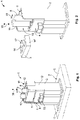
- the connector arrangement 1 has a housing 2 with a receptacle 3, in which a connector 4 and a cable support 5 are received.
- the housing 2 is socket-shaped and fastened to a support 6 (only shown schematically), e.g., a console or a body component.
- the attachment to the support 6 is provided by an attachment section 7, e.g., in the form of a flange that can be arranged on one end of the housing.
- the connector arrangement 1 thus forms a socket into which a mating plug (not shown) that complements the connector 4 can be inserted.
- the connector 4 is standardised and configured in accordance with an industry or company standard.
- the connector 4 is attached to at least one cable 8 and has at least one contact element not shown in fig. 1 , which is conductively connected with a lead 9 of the cable 7.
- Fig. 1 shows two cables by way of example only.
- the cable support 5 is arranged on a cable-side end 10 of the housing 2 in the receptacle 3.
- the receptacle 3 can be open not only on the cable-side end 10 of the housing 2, but also perpendicular to it, on one side.
- plug-side end 11 the receptacle may be laterally circumferentially closed and enclose the connector 4.
- the unilaterally open receptacle 3 on the cable-side end 10 is formed, e.g., by extending one part, here three, of the side walls 12 surrounding the receptacle 3 into a shroud.
- the connector 4 is inserted into the housing 2 in its completely assembled state, and locks in place there, e.g., by a unit 13.
- the at least one cable 9 is retained free of play, in particular, clamped, in a retaining hole 14.
- the receptacle 3 is closed on the cable end 10 by the cable support 5.
- the support as seen in the longitudinal direction 15 of the cable 8, is positioned between the cable end 10 of the housing 2 and the connector 4.
- the cable support 5 is directly supported by the housing 2, such that it prevents relative movement between the cables 9 and the housing 2. Thus, it absorbs vibrations that would otherwise be transferred via the at least one cable 9 to the connector 4 and could cause a relative movement there via the mating plug (not shown). Such a relative movement may result in increased wear of the contacts of the connector 4 and the mating plug.
- the connector 4 is not between the cable support 5 and the housing 2, such that it can be kept free of vibrations.
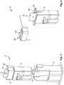
- Fig. 2 shows a cable support 5, the at least one retaining hole 14 of which is open laterally, such that it can be moved laterally, perpendicularly to the longitudinal direction 15 of the cables, onto the at least one cable 8, as indicated by the arrow 15.
- the cable support 5 can be inserted from the cable end 10 and/or the lateral opening 16 of the receptacle 3 into the housing 2.
- a clear width 17 of the retaining hole 14 is smaller than the external diameter 18 of the cable 8 at least when the cable support 5 is in the receptacle 3.
- an external insulation layer 19 of the cable which is generally somewhat resilient, is compressed such that the cable 8 is securely clamped in the retaining hole 14.
- the cable support 5 may be oversized compared to the receptacle 3, such that it and the retaining hole 14 are elastically pressed together when inserted.
- the cable support 5 itself may be arranged fully within the receptacle 3 with no play or at least with at least less play than the connector 4, and the retaining hole 14 may be elastically expanded by the cable 8, thus also resulting in secure clamping of the cable 8.
- the retaining hole 14 is closed on all sides, thus completely enclosing the cable 8.
- one end of the cable 8 must be guided through the hole 14 in order to mount the cable support 5 on the cable 8.
- the cable support 5 can be inserted into the receptacle 3 of the housing 2.
- the plug 4 can first be inserted into the housing 2, and the cable support 5 can then be moved along the at least one cable 8 into the receptacle 3.
- Fig. 3 also shows that the cable support 5 has a form-fitting element 20.
- the housing 2 has a form-fitting element 21 that complements the form-fitting element 20.
- the form-fitting elements 20, 21 may interact to form a linear guide along which the cable support 5 is guided movably into the receptacle 3 in the longitudinal direction 15 of the cable 8.
- the form-fitting elements 20, 21 are configured such that they allow for the cable support 5 to fit with little, or preferably no, play in the housing 2.
- the form-fitting elements 20, 21 may have a press fit.
- the form-fitting elements 20, 21 are configured in the form of a tongue and groove arrangement that allows for movement of the cable support along the direction of insertion 22 of the plug 4 into the housing 2 or in the direction of the longitudinal extent of the cable 8, whilst preventing movement in other directions.
- the form-fitting elements 20, 21 may contain catch means (not shown) with which the cable support 5 locks into place in the receptacle 3.
- the teeth 14' may advantageously be deflected towards one another, reducing the clear width 17.
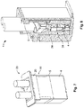
- the cable support 5 is pre-mounted on the connector 4, such that the two form a unit 23.
- the cable support 5 may, in particular, be arranged in the cubage of the connector 4 and close a cable-side opening 24 of the connector 4.
- the cable support 5 in this configuration also has at least one support or form-fitting element 20, supported in the receptacle 3 and/or directly engageable with the form-fitting element 21 of the housing 2.
- the support or form-fitting element 20 is accessible from the outside, in particular protrudes out of the connector 4.
- the connector 4 can have at least one additional form-fitting element 25 that interacts with the form-fitting element 20 or other form-fitting elements 26 of the cable support 5 and secures the cable support 5 on the connector 4.
- the form-fitting elements 20, 25, and/or 26 may form a linear guide for the cable support 5, along which the cable support 5 is at least partially guided movably into the connector 4 in the longitudinal direction 5 of the at least one cable 8.
- the form-fitting elements 20, 25, and/or 26 may additionally allow the cable support 5 to lock in place in the connector 4.
- the at least one cable 8 is directly affixed to the housing 2 via the cable support 5 although the cable support 5 is on the connector 4.
- the cable support 5 affixes the connector 4 on the cable end 10 of the housing both relative to the at least one cable 8 and to the housing 2. This results in a particularly rigid connection between the housing 2 and the connector 4.
- the cable support 5 and the connector 4 can also be assembled into a unit 23.
- the cable support 5 simultaneously also serves as a contact fuse by which the contact elements 27 are affixed in a contact chamber 28 of the connector 4.
- the cable support 5 can lock into place with the connector 4 in two locking positions. In the assembly position 29 shown in fig. 6 , the contact chamber 28 is released for complete insertion of the contact element 27 by the cable support 5.
- the contact elements 27 are directly or indirectly affixed in their final position by the cable support 5.
- the cable support 5 can only be transferred from the mounted position 29 into the operation position 30 when the contact elements 27 are in their final position 31 shown in fig. 8 .
- the path of the cable support 5 from the assembly position 29 to the operating position 30 is blocked directly or indirectly by the contact element 27.
- the cable support 5 may thus serve as a CPA.
- the unit 23 of the embodiment of fig. 6 - 8 also has a form-fitting element 20 that is accessible from outside, in particular a protruding form-fitting element 20, with which the cable support 5 is supported in the receptacle 3.
- the connector 4 is always inserted along the receptacle into the housing from its cable end to its plug end.
- the connector it is also possible for the connector to be inserted into the housing 2 from the side. In this case, the housing 2 would be open on one side, both on the plug end 11 and on the cable end 10.
Claims (4)
- Agencement de connecteur (1) pour une connexion à un connecteur homologue, l'agencement de connecteur (1) ayant un boîtier (2) qui comprend un réceptacle (3), dans lequel au moins un connecteur standardisé (4), configuré conformément à une norme industrielle ou d'entreprise, fixé à au moins un câble (8), est fixé, et une section de fixation (7) pour la fixation du boîtier (2) à un support (6), dans lequel un support de câble (5), lorsqu'il se trouve dans le réceptacle (3), est directement supporté par le boîtier (2) et le support de câble (5) comporte au moins un trou de retenue (14) dans lequel le câble (8) est maintenu sans jeu, dans lequel une largeur libre (17) du trou de retenue (14) est plus petit que le diamètre externe (18) du câble (8) au moins lorsque le support de câble (5) est dans le réceptacle (3), dans lequel le support de câble (5) en association avec le connecteur (4) peuvent être insérés sous forme d'une unité préassemblée (23) dans le boîtier (2), caractérisé en ce qu'un élément à ajustement de forme (20) du support de câble (5) fait saillie hors du connecteur (4) et vient en prise avec un élément à ajustement de forme complémentaire (21) du boîtier (2).
- Agencement de connecteur (1) selon la revendication 1, caractérisé en ce que le au moins un trou de retenue (14) est à l'intérieur d'un cubage du connecteur (4).
- Agencement de connecteur (1) selon l'une quelconque des revendications 1 ou 2, caractérisé en ce que les éléments à ajustement de forme (20, 21) du support de câble (5) et du boîtier (2) forment un guide linéaire le long duquel le support de câble (5) est guidé de manière mobile dans le réceptacle (3).
- Agencement de connecteur (1) selon l'une quelconque des revendications 1 à 3, caractérisé en ce que le support de câble (5) ferme une ouverture côté câble (24) du connecteur (4).
Applications Claiming Priority (1)
| Application Number | Priority Date | Filing Date | Title |
|---|---|---|---|
| DE201310221339 DE102013221339A1 (de) | 2013-10-21 | 2013-10-21 | Buchsenförmiges Umgehäuse, Steckverbinder und Steckverbinderanordnung mit Kabelhalter |
Publications (2)
| Publication Number | Publication Date |
|---|---|
| EP2863486A1 EP2863486A1 (fr) | 2015-04-22 |
| EP2863486B1 true EP2863486B1 (fr) | 2020-10-07 |
Family
ID=51690968
Family Applications (1)
| Application Number | Title | Priority Date | Filing Date |
|---|---|---|---|
| EP14189014.5A Active EP2863486B1 (fr) | 2013-10-21 | 2014-10-15 | Agencement de connecteurs avec support de câble |
Country Status (6)
| Country | Link |
|---|---|
| US (2) | US9941625B2 (fr) |
| EP (1) | EP2863486B1 (fr) |
| JP (1) | JP6448124B2 (fr) |
| CN (1) | CN104617436B (fr) |
| DE (1) | DE102013221339A1 (fr) |
| IN (1) | IN2014DE02906A (fr) |
Families Citing this family (8)
| Publication number | Priority date | Publication date | Assignee | Title |
|---|---|---|---|---|
| US20150214662A1 (en) * | 2012-09-07 | 2015-07-30 | Yazaki Corporation | Connector affixation structure |
| DE102015201089A1 (de) * | 2015-01-22 | 2016-07-28 | Te Connectivity Germany Gmbh | Zwischengehäuse mit einer CPA-Aufnahme und Steckverbindersysteme umfassend ein solches |
| DE202015103923U1 (de) * | 2015-07-27 | 2015-09-24 | HARTING Electronics GmbH | Elektrischer Steckverbinder |
| US10411399B2 (en) * | 2016-04-07 | 2019-09-10 | Signify Holding B.V. | Electrical cable retention |
| US9882317B1 (en) * | 2016-09-15 | 2018-01-30 | Te Connectivity Corporation | Connector system with hybrid electrical connectors |
| JP6792797B2 (ja) * | 2017-03-01 | 2020-12-02 | 株式会社オートネットワーク技術研究所 | 端子ユニット |
| DE102020126541A1 (de) * | 2020-10-09 | 2022-04-14 | Te Connectivity Germany Gmbh | Fixiervorrichtung zur Fixierung eines Kontaktelements in einem Gehäuse eines Steckers |
| US11923636B2 (en) * | 2021-09-10 | 2024-03-05 | Turck Inc. | Cable connector, cable connector arrangement and d-sub type cable connector |
Citations (4)
| Publication number | Priority date | Publication date | Assignee | Title |
|---|---|---|---|---|
| US4108527A (en) * | 1977-06-23 | 1978-08-22 | Amp Incorporated | Strain relief assembly |
| US20030100215A1 (en) * | 2001-11-29 | 2003-05-29 | Werner Bachman | Durable rj-45 data connector assembly |
| WO2011151181A1 (fr) * | 2010-06-02 | 2011-12-08 | Tyco Electronics Amp Gmbh | Ensemble connecteur pour prise de courant, prise de courant et fabrication d'un câble électrique |
| US20120094525A1 (en) * | 2010-10-18 | 2012-04-19 | Panduit Corp. | Communication Plug with Improved Cable Manager |
Family Cites Families (18)
| Publication number | Priority date | Publication date | Assignee | Title |
|---|---|---|---|---|
| US3873172A (en) * | 1971-12-17 | 1975-03-25 | Amp Inc | Flat multi-conductor cable holder |
| JPS62149175U (fr) * | 1986-03-13 | 1987-09-21 | ||
| JPH0418987U (fr) * | 1990-06-04 | 1992-02-18 | ||
| JP2603233Y2 (ja) * | 1993-02-01 | 2000-03-06 | 住友電装株式会社 | リテーナ |
| US5720629A (en) * | 1996-10-16 | 1998-02-24 | The Whitaker Corporation | Sealed electrical connector |
| JP2000323226A (ja) * | 1999-03-09 | 2000-11-24 | Sumitomo Wiring Syst Ltd | コネクタ |
| JP2004185918A (ja) * | 2002-12-02 | 2004-07-02 | Sumitomo Wiring Syst Ltd | 防水コネクタ |
| JP4097589B2 (ja) * | 2003-10-30 | 2008-06-11 | 日本航空電子工業株式会社 | ケーブル用コネクタ |
| KR100623503B1 (ko) * | 2006-06-30 | 2006-09-15 | (주)에이프러스 씨엠 건축사사무소 | 이탈방지 및 방수구조를 갖는 콘센트와 플러그 |
| US8109789B2 (en) * | 2008-12-12 | 2012-02-07 | Tyco Electronics Corporation | Connector assembly with strain relief |
| ES2367216T3 (es) | 2009-03-12 | 2011-10-31 | Tyco Electronics Amp Gmbh | Conector eléctrico. |
| DE102009032393B4 (de) * | 2009-07-08 | 2015-05-13 | Tyco Electronics Amp Gmbh | Elektrischer Stecker mit einteiligem Steckergehäuse und Montageverfahren |
| JP5682997B2 (ja) * | 2010-04-05 | 2015-03-11 | 日本圧着端子製造株式会社 | 電気コネクタ |
| US20120015541A1 (en) * | 2010-07-15 | 2012-01-19 | Juniper Networks, Inc. | Self-securing power cord |
| DE102011051951A1 (de) * | 2011-07-19 | 2013-01-24 | Phoenix Contact Gmbh & Co. Kg | Steckverbinder mit Zugentlastung |
| DE202012001638U1 (de) * | 2012-02-17 | 2012-03-14 | Tyco Electronics Amp Gmbh | Gehäuse für eine Kontakteinrichtung |
| DE102012102212B4 (de) | 2012-03-15 | 2017-09-14 | Te Connectivity Germany Gmbh | Stecker mit Kabelfixierung, Steckverbindung mit einem solchen Stecker sowie Verfahren zur Verbindungsherstellung zwischen einem solchen Stecker und einem komplementär ausgestalteten Gegenstecker |
| CN203233004U (zh) * | 2013-05-13 | 2013-10-09 | 马玉荣 | 一种用于工业现场通信装置的网络连接器 |
-
2013
- 2013-10-21 DE DE201310221339 patent/DE102013221339A1/de not_active Ceased
-
2014
- 2014-10-10 IN IN2906DE2014 patent/IN2014DE02906A/en unknown
- 2014-10-15 EP EP14189014.5A patent/EP2863486B1/fr active Active
- 2014-10-21 JP JP2014214099A patent/JP6448124B2/ja active Active
- 2014-10-21 US US14/519,922 patent/US9941625B2/en active Active
- 2014-10-21 CN CN201410858136.6A patent/CN104617436B/zh active Active
-
2018
- 2018-02-28 US US15/908,148 patent/US10892584B2/en active Active
Patent Citations (4)
| Publication number | Priority date | Publication date | Assignee | Title |
|---|---|---|---|---|
| US4108527A (en) * | 1977-06-23 | 1978-08-22 | Amp Incorporated | Strain relief assembly |
| US20030100215A1 (en) * | 2001-11-29 | 2003-05-29 | Werner Bachman | Durable rj-45 data connector assembly |
| WO2011151181A1 (fr) * | 2010-06-02 | 2011-12-08 | Tyco Electronics Amp Gmbh | Ensemble connecteur pour prise de courant, prise de courant et fabrication d'un câble électrique |
| US20120094525A1 (en) * | 2010-10-18 | 2012-04-19 | Panduit Corp. | Communication Plug with Improved Cable Manager |
Also Published As
| Publication number | Publication date |
|---|---|
| US10892584B2 (en) | 2021-01-12 |
| IN2014DE02906A (fr) | 2015-06-26 |
| JP6448124B2 (ja) | 2019-01-09 |
| EP2863486A1 (fr) | 2015-04-22 |
| US20150111405A1 (en) | 2015-04-23 |
| US9941625B2 (en) | 2018-04-10 |
| DE102013221339A1 (de) | 2015-04-23 |
| CN104617436B (zh) | 2019-05-10 |
| CN104617436A (zh) | 2015-05-13 |
| US20180191100A1 (en) | 2018-07-05 |
| JP2015111555A (ja) | 2015-06-18 |
Similar Documents
| Publication | Publication Date | Title |
|---|---|---|
| EP2863486B1 (fr) | Agencement de connecteurs avec support de câble | |
| EP3252880B1 (fr) | Ensemble de connecteur électrique avec dispositif de verrouillage amélioré | |
| CN107437680B (zh) | 用于连接两个电气平面触头的连接笼 | |
| EP3457501B1 (fr) | Boîtier de connecteur comprenant un couvercle | |
| KR101916327B1 (ko) | 일체형 접지단자를 구비한 매입형 콘센트 | |
| EP3046189B1 (fr) | Insert de connecteur | |
| KR102426325B1 (ko) | 케이블 변형 완화부 | |
| JP6099723B2 (ja) | ロック封止を有するプラグ要素 | |
| US10847924B2 (en) | Contact device and contact system | |
| US9979146B2 (en) | Connector housing assembly and electrical connector assembly | |
| US9761961B2 (en) | Lead-through terminal | |
| CN110911901A (zh) | 用于容纳在插接连接器的保持框架中的模块元件 | |
| US10622766B2 (en) | Electrical shielding member for a network connector | |
| CN103138064A (zh) | 用于平带式缆线的联接装置和带有平带式缆线的电气装置 | |
| US11228139B2 (en) | Plug connector of an electrical plug connection and set comprising a plug connector and functional element | |
| EP2846416B1 (fr) | Boîtier de connecteur avec un dispositif d'assurance de positionnement terminal intégré de manière monolithique | |
| US20160211613A1 (en) | Housing device for an electrical connection terminal and electrical connection terminal | |
| KR20210093355A (ko) | 복수의 공간적 방향으로 접속시키기 위한 플러그 커넥터 부품 | |
| KR102402303B1 (ko) | 커넥터 | |
| US11569605B2 (en) | Contact device and contact system | |
| EP3316412B1 (fr) | Connecteur destiné à connecter un câble électrique à une carte | |
| US20220115808A1 (en) | Fixation Device for Affixing a Contact Element in a Housing of a Connector | |
| US20080305671A1 (en) | Electrical Plug Connection | |
| KR102073285B1 (ko) | 플러그 접촉부용 래칭 수단 | |
| KR200486277Y1 (ko) | 도어 커넥터 |
Legal Events
| Date | Code | Title | Description |
|---|---|---|---|
| PUAI | Public reference made under article 153(3) epc to a published international application that has entered the european phase |
Free format text: ORIGINAL CODE: 0009012 |
|
| 17P | Request for examination filed |
Effective date: 20141015 |
|
| AK | Designated contracting states |
Kind code of ref document: A1 Designated state(s): AL AT BE BG CH CY CZ DE DK EE ES FI FR GB GR HR HU IE IS IT LI LT LU LV MC MK MT NL NO PL PT RO RS SE SI SK SM TR |
|
| AX | Request for extension of the european patent |
Extension state: BA ME |
|
| RAP1 | Party data changed (applicant data changed or rights of an application transferred) |
Owner name: TE CONNECTIVITY GERMANY GMBH |
|
| R17P | Request for examination filed (corrected) |
Effective date: 20151022 |
|
| RBV | Designated contracting states (corrected) |
Designated state(s): AL AT BE BG CH CY CZ DE DK EE ES FI FR GB GR HR HU IE IS IT LI LT LU LV MC MK MT NL NO PL PT RO RS SE SI SK SM TR |
|
| 17Q | First examination report despatched |
Effective date: 20160330 |
|
| STAA | Information on the status of an ep patent application or granted ep patent |
Free format text: STATUS: EXAMINATION IS IN PROGRESS |
|
| GRAP | Despatch of communication of intention to grant a patent |
Free format text: ORIGINAL CODE: EPIDOSNIGR1 |
|
| STAA | Information on the status of an ep patent application or granted ep patent |
Free format text: STATUS: GRANT OF PATENT IS INTENDED |
|
| RIC1 | Information provided on ipc code assigned before grant |
Ipc: H01R 13/516 20060101ALI20191115BHEP Ipc: H01R 13/58 20060101AFI20191115BHEP Ipc: H01R 13/533 20060101ALI20191115BHEP Ipc: H01R 13/436 20060101ALN20191115BHEP |
|
| RIC1 | Information provided on ipc code assigned before grant |
Ipc: H01R 13/516 20060101ALI20191126BHEP Ipc: H01R 13/58 20060101AFI20191126BHEP Ipc: H01R 13/533 20060101ALI20191126BHEP Ipc: H01R 13/436 20060101ALN20191126BHEP |
|
| INTG | Intention to grant announced |
Effective date: 20191211 |
|
| GRAJ | Information related to disapproval of communication of intention to grant by the applicant or resumption of examination proceedings by the epo deleted |
Free format text: ORIGINAL CODE: EPIDOSDIGR1 |
|
| STAA | Information on the status of an ep patent application or granted ep patent |
Free format text: STATUS: EXAMINATION IS IN PROGRESS |
|
| GRAP | Despatch of communication of intention to grant a patent |
Free format text: ORIGINAL CODE: EPIDOSNIGR1 |
|
| STAA | Information on the status of an ep patent application or granted ep patent |
Free format text: STATUS: GRANT OF PATENT IS INTENDED |
|
| INTC | Intention to grant announced (deleted) | ||
| RIC1 | Information provided on ipc code assigned before grant |
Ipc: H01R 13/516 20060101ALI20200414BHEP Ipc: H01R 13/436 20060101ALN20200414BHEP Ipc: H01R 13/58 20060101AFI20200414BHEP Ipc: H01R 13/533 20060101ALI20200414BHEP |
|
| INTG | Intention to grant announced |
Effective date: 20200506 |
|
| RIC1 | Information provided on ipc code assigned before grant |
Ipc: H01R 13/436 20060101ALN20200423BHEP Ipc: H01R 13/516 20060101ALI20200423BHEP Ipc: H01R 13/533 20060101ALI20200423BHEP Ipc: H01R 13/58 20060101AFI20200423BHEP |
|
| GRAS | Grant fee paid |
Free format text: ORIGINAL CODE: EPIDOSNIGR3 |
|
| GRAA | (expected) grant |
Free format text: ORIGINAL CODE: 0009210 |
|
| STAA | Information on the status of an ep patent application or granted ep patent |
Free format text: STATUS: THE PATENT HAS BEEN GRANTED |
|
| AK | Designated contracting states |
Kind code of ref document: B1 Designated state(s): AL AT BE BG CH CY CZ DE DK EE ES FI FR GB GR HR HU IE IS IT LI LT LU LV MC MK MT NL NO PL PT RO RS SE SI SK SM TR |
|
| REG | Reference to a national code |
Ref country code: GB Ref legal event code: FG4D |
|
| REG | Reference to a national code |
Ref country code: AT Ref legal event code: REF Ref document number: 1322165 Country of ref document: AT Kind code of ref document: T Effective date: 20201015 Ref country code: CH Ref legal event code: EP |
|
| REG | Reference to a national code |
Ref country code: IE Ref legal event code: FG4D |
|
| REG | Reference to a national code |
Ref country code: DE Ref legal event code: R096 Ref document number: 602014070933 Country of ref document: DE |
|
| REG | Reference to a national code |
Ref country code: NL Ref legal event code: MP Effective date: 20201007 |
|
| REG | Reference to a national code |
Ref country code: AT Ref legal event code: MK05 Ref document number: 1322165 Country of ref document: AT Kind code of ref document: T Effective date: 20201007 |
|
| PG25 | Lapsed in a contracting state [announced via postgrant information from national office to epo] |
Ref country code: NL Free format text: LAPSE BECAUSE OF FAILURE TO SUBMIT A TRANSLATION OF THE DESCRIPTION OR TO PAY THE FEE WITHIN THE PRESCRIBED TIME-LIMIT Effective date: 20201007 Ref country code: NO Free format text: LAPSE BECAUSE OF FAILURE TO SUBMIT A TRANSLATION OF THE DESCRIPTION OR TO PAY THE FEE WITHIN THE PRESCRIBED TIME-LIMIT Effective date: 20210107 Ref country code: PT Free format text: LAPSE BECAUSE OF FAILURE TO SUBMIT A TRANSLATION OF THE DESCRIPTION OR TO PAY THE FEE WITHIN THE PRESCRIBED TIME-LIMIT Effective date: 20210208 Ref country code: FI Free format text: LAPSE BECAUSE OF FAILURE TO SUBMIT A TRANSLATION OF THE DESCRIPTION OR TO PAY THE FEE WITHIN THE PRESCRIBED TIME-LIMIT Effective date: 20201007 Ref country code: RS Free format text: LAPSE BECAUSE OF FAILURE TO SUBMIT A TRANSLATION OF THE DESCRIPTION OR TO PAY THE FEE WITHIN THE PRESCRIBED TIME-LIMIT Effective date: 20201007 Ref country code: GR Free format text: LAPSE BECAUSE OF FAILURE TO SUBMIT A TRANSLATION OF THE DESCRIPTION OR TO PAY THE FEE WITHIN THE PRESCRIBED TIME-LIMIT Effective date: 20210108 |
|
| REG | Reference to a national code |
Ref country code: LT Ref legal event code: MG4D |
|
| PG25 | Lapsed in a contracting state [announced via postgrant information from national office to epo] |
Ref country code: IS Free format text: LAPSE BECAUSE OF FAILURE TO SUBMIT A TRANSLATION OF THE DESCRIPTION OR TO PAY THE FEE WITHIN THE PRESCRIBED TIME-LIMIT Effective date: 20210207 Ref country code: PL Free format text: LAPSE BECAUSE OF FAILURE TO SUBMIT A TRANSLATION OF THE DESCRIPTION OR TO PAY THE FEE WITHIN THE PRESCRIBED TIME-LIMIT Effective date: 20201007 Ref country code: SE Free format text: LAPSE BECAUSE OF FAILURE TO SUBMIT A TRANSLATION OF THE DESCRIPTION OR TO PAY THE FEE WITHIN THE PRESCRIBED TIME-LIMIT Effective date: 20201007 Ref country code: LV Free format text: LAPSE BECAUSE OF FAILURE TO SUBMIT A TRANSLATION OF THE DESCRIPTION OR TO PAY THE FEE WITHIN THE PRESCRIBED TIME-LIMIT Effective date: 20201007 Ref country code: AT Free format text: LAPSE BECAUSE OF FAILURE TO SUBMIT A TRANSLATION OF THE DESCRIPTION OR TO PAY THE FEE WITHIN THE PRESCRIBED TIME-LIMIT Effective date: 20201007 Ref country code: ES Free format text: LAPSE BECAUSE OF FAILURE TO SUBMIT A TRANSLATION OF THE DESCRIPTION OR TO PAY THE FEE WITHIN THE PRESCRIBED TIME-LIMIT Effective date: 20201007 Ref country code: BG Free format text: LAPSE BECAUSE OF FAILURE TO SUBMIT A TRANSLATION OF THE DESCRIPTION OR TO PAY THE FEE WITHIN THE PRESCRIBED TIME-LIMIT Effective date: 20210107 |
|
| REG | Reference to a national code |
Ref country code: CH Ref legal event code: PL |
|
| PG25 | Lapsed in a contracting state [announced via postgrant information from national office to epo] |
Ref country code: HR Free format text: LAPSE BECAUSE OF FAILURE TO SUBMIT A TRANSLATION OF THE DESCRIPTION OR TO PAY THE FEE WITHIN THE PRESCRIBED TIME-LIMIT Effective date: 20201007 Ref country code: LU Free format text: LAPSE BECAUSE OF NON-PAYMENT OF DUE FEES Effective date: 20201015 |
|
| REG | Reference to a national code |
Ref country code: DE Ref legal event code: R097 Ref document number: 602014070933 Country of ref document: DE |
|
| REG | Reference to a national code |
Ref country code: BE Ref legal event code: MM Effective date: 20201031 |
|
| PG25 | Lapsed in a contracting state [announced via postgrant information from national office to epo] |
Ref country code: RO Free format text: LAPSE BECAUSE OF FAILURE TO SUBMIT A TRANSLATION OF THE DESCRIPTION OR TO PAY THE FEE WITHIN THE PRESCRIBED TIME-LIMIT Effective date: 20201007 Ref country code: SK Free format text: LAPSE BECAUSE OF FAILURE TO SUBMIT A TRANSLATION OF THE DESCRIPTION OR TO PAY THE FEE WITHIN THE PRESCRIBED TIME-LIMIT Effective date: 20201007 Ref country code: LT Free format text: LAPSE BECAUSE OF FAILURE TO SUBMIT A TRANSLATION OF THE DESCRIPTION OR TO PAY THE FEE WITHIN THE PRESCRIBED TIME-LIMIT Effective date: 20201007 Ref country code: MC Free format text: LAPSE BECAUSE OF FAILURE TO SUBMIT A TRANSLATION OF THE DESCRIPTION OR TO PAY THE FEE WITHIN THE PRESCRIBED TIME-LIMIT Effective date: 20201007 Ref country code: SM Free format text: LAPSE BECAUSE OF FAILURE TO SUBMIT A TRANSLATION OF THE DESCRIPTION OR TO PAY THE FEE WITHIN THE PRESCRIBED TIME-LIMIT Effective date: 20201007 Ref country code: CZ Free format text: LAPSE BECAUSE OF FAILURE TO SUBMIT A TRANSLATION OF THE DESCRIPTION OR TO PAY THE FEE WITHIN THE PRESCRIBED TIME-LIMIT Effective date: 20201007 Ref country code: EE Free format text: LAPSE BECAUSE OF FAILURE TO SUBMIT A TRANSLATION OF THE DESCRIPTION OR TO PAY THE FEE WITHIN THE PRESCRIBED TIME-LIMIT Effective date: 20201007 |
|
| PLBE | No opposition filed within time limit |
Free format text: ORIGINAL CODE: 0009261 |
|
| STAA | Information on the status of an ep patent application or granted ep patent |
Free format text: STATUS: NO OPPOSITION FILED WITHIN TIME LIMIT |
|
| PG25 | Lapsed in a contracting state [announced via postgrant information from national office to epo] |
Ref country code: DK Free format text: LAPSE BECAUSE OF FAILURE TO SUBMIT A TRANSLATION OF THE DESCRIPTION OR TO PAY THE FEE WITHIN THE PRESCRIBED TIME-LIMIT Effective date: 20201007 Ref country code: CH Free format text: LAPSE BECAUSE OF NON-PAYMENT OF DUE FEES Effective date: 20201031 Ref country code: BE Free format text: LAPSE BECAUSE OF NON-PAYMENT OF DUE FEES Effective date: 20201031 Ref country code: LI Free format text: LAPSE BECAUSE OF NON-PAYMENT OF DUE FEES Effective date: 20201031 |
|
| 26N | No opposition filed |
Effective date: 20210708 |
|
| GBPC | Gb: european patent ceased through non-payment of renewal fee |
Effective date: 20210107 |
|
| PG25 | Lapsed in a contracting state [announced via postgrant information from national office to epo] |
Ref country code: AL Free format text: LAPSE BECAUSE OF FAILURE TO SUBMIT A TRANSLATION OF THE DESCRIPTION OR TO PAY THE FEE WITHIN THE PRESCRIBED TIME-LIMIT Effective date: 20201007 Ref country code: IE Free format text: LAPSE BECAUSE OF NON-PAYMENT OF DUE FEES Effective date: 20201015 |
|
| PG25 | Lapsed in a contracting state [announced via postgrant information from national office to epo] |
Ref country code: GB Free format text: LAPSE BECAUSE OF NON-PAYMENT OF DUE FEES Effective date: 20210107 Ref country code: SI Free format text: LAPSE BECAUSE OF FAILURE TO SUBMIT A TRANSLATION OF THE DESCRIPTION OR TO PAY THE FEE WITHIN THE PRESCRIBED TIME-LIMIT Effective date: 20201007 |
|
| PG25 | Lapsed in a contracting state [announced via postgrant information from national office to epo] |
Ref country code: IS Free format text: LAPSE BECAUSE OF FAILURE TO SUBMIT A TRANSLATION OF THE DESCRIPTION OR TO PAY THE FEE WITHIN THE PRESCRIBED TIME-LIMIT Effective date: 20210207 Ref country code: TR Free format text: LAPSE BECAUSE OF FAILURE TO SUBMIT A TRANSLATION OF THE DESCRIPTION OR TO PAY THE FEE WITHIN THE PRESCRIBED TIME-LIMIT Effective date: 20201007 Ref country code: MT Free format text: LAPSE BECAUSE OF FAILURE TO SUBMIT A TRANSLATION OF THE DESCRIPTION OR TO PAY THE FEE WITHIN THE PRESCRIBED TIME-LIMIT Effective date: 20201007 Ref country code: CY Free format text: LAPSE BECAUSE OF FAILURE TO SUBMIT A TRANSLATION OF THE DESCRIPTION OR TO PAY THE FEE WITHIN THE PRESCRIBED TIME-LIMIT Effective date: 20201007 |
|
| PG25 | Lapsed in a contracting state [announced via postgrant information from national office to epo] |
Ref country code: MK Free format text: LAPSE BECAUSE OF FAILURE TO SUBMIT A TRANSLATION OF THE DESCRIPTION OR TO PAY THE FEE WITHIN THE PRESCRIBED TIME-LIMIT Effective date: 20201007 |
|
| PGFP | Annual fee paid to national office [announced via postgrant information from national office to epo] |
Ref country code: IT Payment date: 20230913 Year of fee payment: 10 |
|
| PGFP | Annual fee paid to national office [announced via postgrant information from national office to epo] |
Ref country code: FR Payment date: 20230911 Year of fee payment: 10 |
|
| PGFP | Annual fee paid to national office [announced via postgrant information from national office to epo] |
Ref country code: DE Payment date: 20230830 Year of fee payment: 10 |