EP2862984A1 - Fachwerk zur Verglasung eines Gebäudes - Google Patents
Fachwerk zur Verglasung eines Gebäudes Download PDFInfo
- Publication number
- EP2862984A1 EP2862984A1 EP13401113.9A EP13401113A EP2862984A1 EP 2862984 A1 EP2862984 A1 EP 2862984A1 EP 13401113 A EP13401113 A EP 13401113A EP 2862984 A1 EP2862984 A1 EP 2862984A1
- Authority
- EP
- European Patent Office
- Prior art keywords
- holder
- post
- bolt
- truss
- posts
- Prior art date
- Legal status (The legal status is an assumption and is not a legal conclusion. Google has not performed a legal analysis and makes no representation as to the accuracy of the status listed.)
- Granted
Links
- 239000011521 glass Substances 0.000 claims abstract description 23
- 239000000463 material Substances 0.000 claims description 5
- XEEYBQQBJWHFJM-UHFFFAOYSA-N Iron Chemical compound [Fe] XEEYBQQBJWHFJM-UHFFFAOYSA-N 0.000 abstract 2
- 229910052742 iron Inorganic materials 0.000 abstract 1
- 229910000831 Steel Inorganic materials 0.000 description 3
- 239000010959 steel Substances 0.000 description 3
- 229910000838 Al alloy Inorganic materials 0.000 description 2
- 238000005452 bending Methods 0.000 description 2
- 230000005484 gravity Effects 0.000 description 2
- 241001295925 Gegenes Species 0.000 description 1
- 150000001875 compounds Chemical class 0.000 description 1
- 238000001125 extrusion Methods 0.000 description 1
- 238000004519 manufacturing process Methods 0.000 description 1
- 239000007769 metal material Substances 0.000 description 1
- 230000035515 penetration Effects 0.000 description 1
- 230000002093 peripheral effect Effects 0.000 description 1
- 238000007789 sealing Methods 0.000 description 1
- 239000010935 stainless steel Substances 0.000 description 1
- 229910001220 stainless steel Inorganic materials 0.000 description 1
- 230000003313 weakening effect Effects 0.000 description 1
Images

Classifications
-
- E—FIXED CONSTRUCTIONS
- E04—BUILDING
- E04B—GENERAL BUILDING CONSTRUCTIONS; WALLS, e.g. PARTITIONS; ROOFS; FLOORS; CEILINGS; INSULATION OR OTHER PROTECTION OF BUILDINGS
- E04B2/00—Walls, e.g. partitions, for buildings; Wall construction with regard to insulation; Connections specially adapted to walls
- E04B2/88—Curtain walls
- E04B2/96—Curtain walls comprising panels attached to the structure through mullions or transoms
- E04B2/965—Connections of mullions and transoms
-
- E—FIXED CONSTRUCTIONS
- E06—DOORS, WINDOWS, SHUTTERS, OR ROLLER BLINDS IN GENERAL; LADDERS
- E06B—FIXED OR MOVABLE CLOSURES FOR OPENINGS IN BUILDINGS, VEHICLES, FENCES OR LIKE ENCLOSURES IN GENERAL, e.g. DOORS, WINDOWS, BLINDS, GATES
- E06B3/00—Window sashes, door leaves, or like elements for closing wall or like openings; Layout of fixed or moving closures, e.g. windows in wall or like openings; Features of rigidly-mounted outer frames relating to the mounting of wing frames
- E06B3/54—Fixing of glass panes or like plates
- E06B3/5409—Means for locally spacing the pane from the surrounding frame
Definitions
- the invention relates to a framework for the glazing of a building having the features of the preamble of claim 1.
- Trusses for glazing buildings have posts and bars, the ends of which are attached to the posts. Normally, such trusses are level and their posts and bars are arranged at right angles to each other, which is not mandatory for the invention.
- the posts and bars are profiles, also hollow profiles made of steel or an aluminum alloy.
- the glass panels are nowadays usually not mounted in the level of the truss, but on an outside of the posts and bars in a plane in front of the truss.
- Such trusses are arranged in wall or roof openings to a partial glazing of a building or as a facade, wall or roof to a building.
- the patent application EP 1 681 398 A2 discloses a T-connector for attaching one end of a latch to a post of a truss for glazing a building.
- the posts and bars are different hollow profiles.
- Holders with cylindrical heads are fastened in ends of the latches, which protrude from the ends of the latch and engage in circular holes in a side wall of a post.
- the side wall of the post which is a hollow profile, is that wall of the post against which the end of the bar rests.
- Spring detents in the cylinder heads of the holders engage behind the side wall of the post so that the end of the bolt is inextricably linked to the post.
- the publication DE 42 10 575 A1 also discloses a T-joint of a bolt and a post of a truss for glazing a building.
- the bolt is a T-beam whose flange is hollow with two flat chambers of rectangular cross-section formed on either side of a web of the T-beam.
- the chambers in the flange of the bolt form receptacles in which strip-shaped holders with the same cross-section as the chambers are slidably received.
- the posts of the known truss are double T-beams, one flange of which, like the flange of the bolt, is hollow with two flat chambers of rectangular cross-section on either side of a web of the double-T beam.
- For attachment of the latch in each case two receiving openings in the bars facing outer sides of the chambers are mounted in the hollow flange of the post, in which engage the holder of the bolt.
- the object of the invention is to increase the rigidity of a truss of the type described above.
- a holder with which one end of a bolt is fastened to a post of a truss is pivotally fixed both on the bolt and on the post. What is needed is a vertical swivel resistance to gravity which depends on a location of the finished truss. Due to the swivel resistance of the holder both on the post and on the bolt, the end of the bolt is pivotally held on the post. A bending strength of the bolt is thereby increased. In a vertical load, the bolt bends less because its two ends are held pivotally, as he would bend if its two ends could pivot. A rigidity of the framework according to the invention in the plane of the truss is increased by the pivotal attachment of the ends of the bolt to the post. The invention allows longer bars and larger post spacing.
- an embodiment of the invention provides that the post has two spaced apart receiving openings, which passes through the holder.
- a penetration in this sense is to be understood as an intervention of an end of the holder.
- the holder consists of a flat material, ie a strip-shaped material which is thinner than wide and whose thickness is in particular a fraction of its width.
- the holder may be a flat steel or a sheet of another metallic or non-metallic material.
- a holder made of a flat material is inexpensive and has a high bending stiffness in the direction of its width, i. around a vertical axis normal to its large area.
- a high swing strength against gravity is achieved by placing the sheet horizontally, i. is arranged horizontally with its longitudinal direction and its width vertically in the erected truss.
- a flat material arranged in this way also takes up little space in a depth direction of the framework, so that a weakening of the posts through the receiving openings is small.
- an embodiment of the invention provides a bolt which has a running in its longitudinal direction chamber as a receptacle for the holder.
- a wall of the bolt is double-walled or designed as a hollow wall, so that the chamber as a receptacle for the holder results.
- the chamber has the same cross-section as the holder, so that the holder is pluggable into the chamber or displaceable in the chamber.
- An embodiment of the invention provides that the posts have a hollow profile, in the side walls of the receiving openings for the passage or engagement of the holder are attached.
- the receiving openings are spaced from each other according to a distance of the side walls of the post, so that a plugged-holder is pivotal with the post.
- the sidewalls are understood to be the walls of the hollow profile of the posts to which the ends of the bolts are fastened.
- a preferred embodiment of the invention provides that the posts and the bars of the framework have the same hollow profiles. This saves different profiles for the posts and latches.
- an embodiment of the invention provides glass holders which protrude on one side from the framework and can be placed on the glass panes. According to the glass holder are inserted into fixing holes in the holder and the bolt and thereby fix the holder immovable on or in the bolt. The glass holder thus serve at the same time the attachment of the holder on or in the bolt.
- the fixing holes in the holder and in the bar can overlap or lie apart.
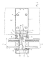
- two receiving openings 4 with the same shape and size as cross-sections of the chambers 3 are mounted in side walls of the post 2, which open into the chamber 3 of the post 2.
- a flat steel is inserted as a holder 5, which protrudes on both sides of the post 2.
- the holder 5 has the same cross-section as the receiving openings 4 and the chambers 3. Because the receiving openings 4 in the side walls of the post 2 by the width of the post 2 are spaced from each other and keep the holder 5 due to the same cross-sections clearance or virtually no play, is the Holder 5, which passes through the two receiving openings 4 of the post 2, pivotally attached to the post 2.
- the two bars 1 are inserted with their chambers 3, wherein the bolt 1 held in the correct position to the post 2 for mounting and the holder 5 by back and forth in the post 2 in the chambers. 3 the latch 1 can be pushed. Because of the same Cross-sections of the holder 5 and the chambers 3, the bolt 1 are pivotally mounted on the holder 5 and connected via the holder 5 pivotally connected to the post 2. Due to the pivotal fastening of the bolt 1 on the post 2, a load capacity of the bolt 1 is increased, its deflection under load is smaller than it would be if the ends of the bolt 1 could pivot on the post 2.
- a cylinder head screw 6 is screwed into the ends of the bolt 1, the cylinder head projects beyond the end of the bolt 1 and engages in a drilled hole 7 in the post 2.
- the cylinder head bolts 6 hold the bolt 1 against tilting about their imaginary longitudinal axes.
- the bolt 1 (and also the post 2 because of their identical hollow profile) four screw 8.
- the screw 8 are located in the hollow sections, they are cylindrical tube-shaped, axially parallel and are open for manufacturing reasons at a peripheral location.
- the glass holder 11 T-shaped plates, for example, made of stainless steel, wherein a crosshead of the T-shaped glass holder 11 are thick about as deep as the truss to be fixed glass sheets. By depth is meant a board of the glass holder 11 on the front of the bolt 1 and the framework.
- glass panes 13 double-glazed in the exemplary embodiment insulating glass panes are placed on the glass holder 11 and with attached strip-shaped holders 14, the edges of the glass panes 13 engage on the truss facing away from the outside.
- the holder 14 are fastened with screws 15 to the truss, which are screwed into U-shaped screw 16, which are integral parts of the hollow sections of the bolt 1 and the post 2 and in a center of the front sides of the bolt 1 and the post 2 in the Extend longitudinally.
- the glass sheets 13 are located in a plane parallel to a plane of the framework immediately before the truss, namely on the front and outer sides of the bolt 1 and the post 2.
- connection shown is a double-T connection with two bars 1, the same axis abut against the two sides of the post 2.
- a simple T-connection with only one bolt 1 on one side of a post 2 is possible by the holder 5, which is accommodated in the chamber 3 of the bolt 1, only by the width of the post 2 from the end of the bolt 1 protrudes and ends flush with the post 2 on a side opposite the latch 1 side.
- the holder 5 For immovable fixation on or in the post 2 of the holder 5 is fixed in this case in a suitable manner, for example with a clamping screw, not shown. Because the holder 5 engages in this case, the receiving opening 4 in the bolt 1 facing side wall of the post 2 and engages in the receiving opening 4 in the opposite side of the bolt 1 of the post 2, the holder 5 even with a simple T-connection pivotally attached to the post 2.
Landscapes
- Engineering & Computer Science (AREA)
- Civil Engineering (AREA)
- Structural Engineering (AREA)
- Architecture (AREA)
- Physics & Mathematics (AREA)
- Electromagnetism (AREA)
- Load-Bearing And Curtain Walls (AREA)
Abstract
Description
- Die Erfindung betrifft ein Fachwerk zur Verglasung eines Gebäudes mit den Merkmalen des Oberbegriffs des Anspruchs 1.
- Fachwerke zur Verglasung von Gebäuden weisen Pfosten und Riegel auf, deren Enden an den Pfosten befestigt sind. Normalerweise sind solche Fachwerke eben und ihre Pfosten und Riegel sind rechtwinklig zueinander angeordnet, was allerdings nicht zwingend für die Erfindung ist. Normalerweise sind die Pfosten und Riegel Profile, auch Hohlprofile aus Stahl oder einer Aluminiumlegierung. In von den Pfosten und Riegeln umschlossenen Fächern werden Glasscheiben angeordnet, wobei die Glasscheiben heutzutage meist nicht in der Ebene des Fachwerks, sondern auf einer Außenseite der Pfosten und Riegel in einer Ebene vor dem Fachwerk angebracht sind. Solche Fachwerke werden in Wand- oder Dachöffnungen zu einer Teilverglasung eines Gebäudes oder auch als Fassade, Wand oder Dach an einem Gebäude angeordnet.
- Die Patentanmeldung
EP 1 681 398 A2 offenbart einen T-Verbinder zur Befestigung eines Endes eines Riegels an einem Pfosten eines Fachwerks zur Verglasung eines Gebäudes. Die Pfosten und Riegel sind unterschiedliche Hohlprofile. In Enden der Riegel sind Halter mit zylinderförmigen Köpfen befestigt, die aus den Enden der Riegel vorstehen und in kreisförmige Löcher in einer Seitenwand eines Pfostens eingreifen. Die Seitenwand des Pfostens, der ein Hohlprofil ist, ist diejenige Wand des Pfosten, an der das Ende des Riegels anliegt. Federnde Rasten in den Zylinderköpfen der Halter hintergreifen die Seitenwand des Pfostens, so dass das Ende des Riegels unlösbar mit dem Pfosten verbunden ist. - Die Offenlegungsschrift
DE 42 10 575 A1 offenbart ebenfalls eine T-Verbindung eines Riegels und eines Pfostens eines Fachwerks zur Verglasung eines Gebäudes. Der Riegel ist ein T-Träger, dessen Flansch hohl mit zwei flachen Kammern mit rechteckigem Querschnitt beiderseits eines Stegs des T-Trägers ausgebildet ist. Die Kammern im Flansch des Riegels bilden Aufnahmen, in denen streifenförmige Halter mit gleichem Querschnitt wie die Kammern verschiebbar aufgenommen sind. Die Pfosten des bekannten Fachwerks sind Doppel-T-Träger, deren einer Flansch wie der Flansch der Riegel hohl mit zwei flachen Kammern mit rechteckigem Querschnitt beiderseits eines Stegs des Doppel-T-Trägers ausgebildet ist. Zur Befestigung der Riegel werden jeweils zwei Aufnahmeöffnungen in den Riegeln zugewandten Außenseiten der Kammern in dem hohlen Flansch des Pfostens angebracht, in die die Halter der Riegel eingreifen. - Aufgabe der Erfindung ist eine Steifigkeit eines Fachwerks der vorstehend erläuterten Art zu erhöhen.
- Diese Aufgabe wird erfindungsgemäß durch die Merkmale des Anspruchs 1 gelöst. Erfindungsgemäß ist ein Halter, mit dem ein Ende eines Riegels an einem Pfosten eines Fachwerks befestigt ist, sowohl am Riegel als auch am Pfosten schwenkfest. Notwendig ist eine Schwenkfestigkeit in vertikaler Richtung gegen Schwerkraft, die von einer Lage des fertig errichteten Fachwerks abhängig ist. Durch die Schwenkfestigkeit des Halters sowohl am Pfosten als auch am Riegel ist das Ende des Riegels schwenkfest am Pfosten gehalten. Eine Biegefestigkeit des Riegels ist dadurch erhöht. Bei einer vertikalen Belastung biegt sich der Riegel weniger durch, weil seine beiden Enden schwenkfest gehalten sind, als er sich durchbiegen würde, wenn seine beiden Enden schwenken könnten. Eine Steifigkeit des erfindungsgemäßen Fachwerks in der Ebene des Fachwerks ist durch die schwenkfeste Befestigung der Enden der Riegel an den Pfosten erhöht. Die Erfindung ermöglicht längere Riegel und größere Pfostenabstände.
- Zur schwenkfesten Befestigung des Halters an einem Pfosten des Fachwerks sieht eine Ausgestaltung der Erfindung vor, dass der Pfosten zwei voneinander beabstandete Aufnahmeöffnungen aufweist, die der Halter durchgreift. Unter einem Durchgreifen in diesem Sinne ist auch ein Eingreifen eines Endes des Halters zu verstehen. Durch den Durch- oder Eingriff des Halters in zwei beabstandeten Aufnahmeöffnungen des Pfostens ist der Halter schwenkfest am Pfosten gehalten.
- Vorzugsweise besteht der Halter aus einem Flachmaterial, also einem streifenförmigen Material, das dünner als breit ist und dessen Dicke insbesondere einen Bruchteil seiner Breite beträgt. Der Halter kann ein Flachstahl oder ein Flachmaterial aus einem anderen metallischen oder nicht-metallischen Werkstoff sein. Ein Halter aus einem Flachmaterial ist preisgünstig und weist eine hohe Biegesteifigkeit in Richtung seiner Breite auf, d.h. um eine Hochachse normal zu seiner großen Fläche. Eine hohe Schwenkfestigkeit gegen Schwerkraft wird erreicht, indem das Flachmaterial horizontal stehend, d.h. mit seiner Längsrichtung horizontal und seiner Breite vertikal im errichteten Fachwerk angeordnet wird. In einem vertikal stehenden Fachwerk nimmt ein solchermaßen angeordnetes Flachmaterial zudem wenig Platz in einer Tiefenrichtung des Fachwerks in Anspruch, so dass eine Schwächung der Pfosten durch die Aufnahmeöffnungen klein ist.
- Grundsätzlich genügt eine Aufnahme im Riegel, die den Halter nur an wenigen Stellen, im Minimalfall nur an zwei Stellen hält. Allerdings sieht eine Ausgestaltung der Erfindung einen Riegel vor, der eine in seiner Längsrichtung verlaufende Kammer als Aufnahme für den Halter aufweist. Zur Ausbildung der Kammer ist beispielsweise eine Wand des Riegels doppelwandig oder als Hohlwand ausgeführt, so dass sich die Kammer als Aufnahme für den Halter ergibt. Vorzugsweise weist die Kammer denselben Querschnitt wie der Halter auf, so dass der Halter in die Kammer steckbar bzw. in der Kammer verschiebbar ist.
- Eine Ausgestaltung der Erfindung sieht vor, dass die Pfosten ein Hohlprofil aufweisen, in dessen Seitenwänden die Aufnahmeöffnungen für den Durchgriff oder Eingriff des Halters angebracht sind. Die Aufnahmeöffnungen sind entsprechend einem Abstand der Seitenwände des Pfostens voneinander beabstandet, so dass ein durchgesteckter Halter schwenkfest mit dem Pfosten ist. Als Seitenwände werden die Wände des Hohlprofils der Pfosten verstanden, an denen die Enden der Riegel befestigt sind.
- Eine bevorzugte Ausgestaltung der Erfindung sieht vor, dass die Pfosten und die Riegel des Fachwerks gleiche Hohlprofile aufweisen. Das erspart unterschiedliche Profile für die Pfosten und die Riegel.
- Zum Anbringen von Glasscheiben sieht eine Ausgestaltung der Erfindung Glashalter vor, die auf einer Seite vom Fachwerk vorstehen und auf die Glasscheiben aufsetzbar sind. Erfindungsgemäß sind die Glashalter in Fixieröffnungen im Halter und im Riegel gesteckt und fixieren dadurch den Halter unverschieblich am oder im Riegel. Die Glashalter dienen also gleichzeitig der Befestigung des Halters am bzw. im Riegel. Die Fixieröffnungen im Halter und im Riegel können einander überdecken oder auseinander liegen.
- Die Erfindung wird nachfolgend anhand eines in der Zeichnung dargestellten Ausführungsbeispiels näher erläutert. Es zeigen:
- Figur 1
- eine perspektivische Darstellung einer Verbindungsstelle zweier Riegel und eines Pfostens eines Fachwerks gemäß der Erfindung; und
- Figur 2
- einen Querschnitt durch einen Riegel mit Ansicht des Pfostens der Verbindung aus
Figur 1 . - Zur Herstellung der Verbindung sind in Seitenwänden des Pfostens 2 zwei Aufnahmeöffnungen 4 mit gleicher Form und Größe wie Querschnitte der Kammern 3 angebracht, die in die Kammer 3 des Pfostens 2 münden. Durch die Aufnahmeöffnungen 4 ist ein Flachstahl als Halter 5 gesteckt, der auf beiden Seiten aus dem Pfosten 2 vorsteht. Der Halter 5 hat denselben Querschnitt wie die Aufnahmeöffnungen 4 und die Kammern 3. Weil die Aufnahmeöffnungen 4 in den Seitenwänden des Pfostens 2 um die Breite des Pfostens 2 voneinander beabstandet sind und den Halter 5 aufgrund der gleichen Querschnitte spielfrei oder nahezu spielfrei halten, ist der Halter 5, der die beiden Aufnahmeöffnungen 4 des Pfostens 2 durchgreift, schwenkfest am Pfosten 2 befestigt. Auf den beidseitig aus dem Pfosten 2 vorstehenden Halter 5 sind die beiden Riegel 1 mit ihren Kammern 3 gesteckt, wobei zur Montage auch die Riegel 1 lagerichtig an den Pfosten 2 gehalten und der Halter 5 durch Hin- und Herschieben im Pfosten 2 in die Kammern 3 der Riegel 1 geschoben werden kann. Aufgrund der gleichen Querschnitte des Halters 5 und der Kammern 3 sind die Riegel 1 schwenkfest am Halter 5 befestigt und über den Halter 5 schwenkfest mit dem Pfosten 2 verbunden. Durch die schwenkfeste Befestigung der Riegel 1 am Pfosten 2 ist eine Belastbarkeit der Riegel 1 erhöht, ihre Durchbiegung bei Belastung ist kleiner als sie wäre, wenn die Enden der Riegel 1 an den Pfosten 2 schwenken könnten.
- In einem hinteren Teil ist jeweils eine Zylinderkopfschraube 6 in die Enden der Riegel 1 geschraubt, deren Zylinderkopf über das Ende der Riegel 1 übersteht und in ein gebohrtes Loch 7 im Pfosten 2 eingreift. Die Zylinderkopfschrauben 6 halten die Riegel 1 gegen ein Kippen um ihre gedachten Längsachsen. Zum Einschrauben der Zylinderkopfschrauben 6 weisen die Riegel 1 (und ebenso die Pfosten 2 wegen ihres identischen Hohlprofils) vier Schraubkanäle 8 auf. Die Schraubkanäle 8 befinden sich in den Hohlprofilen, sie sind zylinderrohrförmig, verlaufen achsparallel und sind aus fertigungstechnischen Gründen an einer Umfangsstelle offen.
- In den Vorderseiten der Riegel 1 sind Schlitze deckungsgleich mit Schlitzen im Halter 5 als Fixieröffnungen 9, 10 angebracht, durch bzw. in die Glashalter 11 gesteckt sind, die den Halter 5 unverschieblich in den Kammern 3 der Riegel 1 fixieren. Durch die Anlage der Enden der Riegel 1 an den Seitenwänden des Pfostens 2 sind die Halter 5 und die Riegel 1 somit auch unverschieblich an den Pfosten 2 fixiert. Im Ausführungsbeispiel sind die Glashalter 11 T-förmige Platten beispielsweise aus nicht rostendem Stahl, wobei ein Querhaupt der T-förmigen Glashalter 11 in etwa so tief wie am Fachwerk zu befestigende Glasscheiben dick sind. Mit Tiefe ist ein Vorstand der Glashalter 11 über die Vorderseite der Riegel 1 bzw. des Fachwerks gemeint. Durch Eindrehen einer dargestellten Klemmschraube 12, beispielsweise einer Madenschraube (siehe
Figur 2 ), durch Löcher in den Glashaltern 11 werden die Glashalter 11 an den Riegeln 1 festgeklemmt, so dass sie sich nicht aus den Fixieröffnungen 9, 10 herausziehen lassen oder ungewollt vom Fachwerk lösen. - Wie in
Figur 2 zu sehen werden Glasscheiben 13, im Ausführungsbeispiel doppelt verglaste Isolierglasscheiben auf die Glashalter 11 aufgesetzt und mit leistenförmigen Haltern 14 befestigt, die Ränder der Glasscheiben 13 auf dem Fachwerk abgewandten Außenseiten übergreifen. Die Halter 14 sind mit Schrauben 15 am Fachwerk befestigt, die in U-förmige Schraubkanäle 16 eingeschraubt sind, die einstückige Bestandteile der Hohlprofile der Riegel 1 und der Pfosten 2 sind und sich in einer Mitte der Vorderseiten der Riegel 1 und der Pfosten 2 in deren Längsrichtung erstrecken. Die Glasscheiben 13 befinden sich in einer Ebene parallel zu einer Ebene des Fachwerks unmittelbar vor dem Fachwerk, nämlich auf den Vorder- bzw. Außenseiten der Riegel 1 und der Pfosten 2. Zwischen dem Fachwerk, also den Riegeln 1 und den Pfosten 2, und den Glasscheiben 13 einerseits und den Glasscheiben 13 und den Haltern 14 andererseits sind gummielastische Dichtprofile 17, 18 angeordnet. Die dargestellte Verbindung ist eine Doppel-T-Verbindung mit zwei Riegeln 1, die gleichachsig gegen die beiden Seiten des Pfostens 2 stoßen. In sinngemäß gleicher Weise ist auch eine einfache T-Verbindung mit nur einem Riegel 1 auf einer Seite eines Pfostens 2 möglich, indem der Halter 5, der in der Kammer 3 des Riegels 1 aufgenommen ist, nur um die Breite des Pfostens 2 aus dem Ende des Riegels 1 vorsteht und auf einer dem Riegel 1 gegenüberliegenden Seite bündig mit dem Pfosten 2 endet. Zur unverschieblichen Fixierung am bzw. im Pfosten 2 wird der Halter 5 in diesem Fall in geeigneter Weise befestigt, beispielsweise mit einer nicht dargestellten Klemmschraube. Weil der Halter 5 auch in diesem Fall die Aufnahmeöffnung 4 in der dem Riegel 1 zugewandten Seitenwand des Pfostens 2 durchgreift und in die Aufnahmeöffnung 4 in der dem Riegel 1 gegenüberliegenden Seitenwand des Pfostens 2 eingreift, ist der Halter 5 auch bei einer einfachen T-Verbindung schwenkfest am Pfosten 2 befestigt.
Claims (7)
- Fachwerk zur Verglasung eines Gebäudes, mit Pfosten (2) und Riegeln (1), deren Enden an den Pfosten (2) befestigt sind, wobei die Riegel (1) eine Aufnahme (3) für einen Halter (5) aufweisen, der schwenkfest in der Aufnahme (3) des Riegels (1) ist und aus einem Ende des Riegels (1) vorsteht und in eine Aufnahmeöffnung (4) für den Halter (5) in einem Pfosten (2) eingreift, dadurch gekennzeichnet, dass der Halter (5) schwenkfest im Pfosten (2) gehalten ist.
- Fachwerk nach Anspruch 1, dadurch gekennzeichnet, dass der Halter (5) zwei beabstandete Aufnahmeöffnungen (4) des Pfostens (2) durchgreift.
- Fachwerk nach Anspruch 1 oder 2, dadurch gekennzeichnet, dass der Halter (5) ein Flachmaterial aufweist.
- Fachwerk nach einem der Ansprüche 1 bis 3, dadurch gekennzeichnet, dass der Riegel (1) eine in seiner Längsrichtung verlaufende Kammer als Aufnahme (3) für den Halter (5) aufweist.
- Fachwerk nach einem der Ansprüche 2 bis 4, dadurch gekennzeichnet, dass der Pfosten (2) ein Hohlprofil aufweist, und dass die beabstandeten Aufnahmeöffnungen (4) für den Halter (5) in Seitenwänden des Hohlprofils angebracht sind.
- Fachwerk nach einem der vorhergehenden Ansprüche, dadurch gekennzeichnet, dass die Pfosten (2) und Riegel (3) identische Hohlprofile aufweisen.
- Fachwerk nach einem der vorhergehenden Ansprüche, dadurch gekennzeichnet, dass das Fachwerk Glashalter (11) aufweist, die in Fixieröffnungen (9, 10) im Halter (5) und in dem einen Ende der Riegel (1) gesteckt sind und den Halter (5) unverschieblich im Riegel (1) halten.
Priority Applications (1)
| Application Number | Priority Date | Filing Date | Title |
|---|---|---|---|
| EP13401113.9A EP2862984B1 (de) | 2013-10-17 | 2013-10-17 | Fachwerk zur Verglasung eines Gebäudes |
Applications Claiming Priority (1)
| Application Number | Priority Date | Filing Date | Title |
|---|---|---|---|
| EP13401113.9A EP2862984B1 (de) | 2013-10-17 | 2013-10-17 | Fachwerk zur Verglasung eines Gebäudes |
Publications (2)
| Publication Number | Publication Date |
|---|---|
| EP2862984A1 true EP2862984A1 (de) | 2015-04-22 |
| EP2862984B1 EP2862984B1 (de) | 2017-03-22 |
Family
ID=49958215
Family Applications (1)
| Application Number | Title | Priority Date | Filing Date |
|---|---|---|---|
| EP13401113.9A Not-in-force EP2862984B1 (de) | 2013-10-17 | 2013-10-17 | Fachwerk zur Verglasung eines Gebäudes |
Country Status (1)
| Country | Link |
|---|---|
| EP (1) | EP2862984B1 (de) |
Cited By (2)
| Publication number | Priority date | Publication date | Assignee | Title |
|---|---|---|---|---|
| CN105089185A (zh) * | 2015-06-23 | 2015-11-25 | 浙江亚厦幕墙有限公司 | 一种立柱与横梁的连接结构及利用该连接结构进行连接的方法 |
| FR3110628A1 (fr) * | 2020-05-20 | 2021-11-26 | Vulcain | Cloison vitrée coupe-feu |
Citations (5)
| Publication number | Priority date | Publication date | Assignee | Title |
|---|---|---|---|---|
| FR1277982A (fr) * | 1960-07-11 | 1961-12-08 | Cloison à ossature métallique | |
| NL8204319A (nl) * | 1982-11-08 | 1984-06-01 | Nijs & Vale B V | Gevelconstructie. |
| DE4210575A1 (de) | 1992-03-31 | 1993-10-07 | Herbert Lacker | Unterkonstruktion für Glasdächer und Glasfassaden |
| EP1098046A2 (de) * | 1999-11-03 | 2001-05-09 | RP Technik GmbH Profilsysteme | Verkleidungssystem für Fassaden und Dächer von Bauwerken |
| EP1681398A2 (de) | 2005-01-15 | 2006-07-19 | SCHÜCO International KG | T-Verbinder für eine aus Pfosten- und quer dazu verlaufenden Riegelprofilen gebildeten Fachwerkkonstruktion |
-
2013
- 2013-10-17 EP EP13401113.9A patent/EP2862984B1/de not_active Not-in-force
Patent Citations (5)
| Publication number | Priority date | Publication date | Assignee | Title |
|---|---|---|---|---|
| FR1277982A (fr) * | 1960-07-11 | 1961-12-08 | Cloison à ossature métallique | |
| NL8204319A (nl) * | 1982-11-08 | 1984-06-01 | Nijs & Vale B V | Gevelconstructie. |
| DE4210575A1 (de) | 1992-03-31 | 1993-10-07 | Herbert Lacker | Unterkonstruktion für Glasdächer und Glasfassaden |
| EP1098046A2 (de) * | 1999-11-03 | 2001-05-09 | RP Technik GmbH Profilsysteme | Verkleidungssystem für Fassaden und Dächer von Bauwerken |
| EP1681398A2 (de) | 2005-01-15 | 2006-07-19 | SCHÜCO International KG | T-Verbinder für eine aus Pfosten- und quer dazu verlaufenden Riegelprofilen gebildeten Fachwerkkonstruktion |
Cited By (2)
| Publication number | Priority date | Publication date | Assignee | Title |
|---|---|---|---|---|
| CN105089185A (zh) * | 2015-06-23 | 2015-11-25 | 浙江亚厦幕墙有限公司 | 一种立柱与横梁的连接结构及利用该连接结构进行连接的方法 |
| FR3110628A1 (fr) * | 2020-05-20 | 2021-11-26 | Vulcain | Cloison vitrée coupe-feu |
Also Published As
| Publication number | Publication date |
|---|---|
| EP2862984B1 (de) | 2017-03-22 |
Similar Documents
| Publication | Publication Date | Title |
|---|---|---|
| DE69802262T2 (de) | Befestigungsplatte für trennwandsystem | |
| DE29917734U1 (de) | Aus einem Profilelement gebildete Montageschiene | |
| DE60314459T2 (de) | Bauelement für die mantelbetonbauweise | |
| DE2610998C3 (de) | Halterung zur Befestigung von Bekleidungsplatten vor einer Bauwerkswand | |
| DE202010008019U1 (de) | Gebäudefassade mit zweiteiligen Abstandshaltern | |
| EP2862984B1 (de) | Fachwerk zur Verglasung eines Gebäudes | |
| DE69226207T2 (de) | Verbesserungen an regalen | |
| EP2098650A2 (de) | Schalungselement | |
| DE2923903A1 (de) | Wandbefestigungselement fuer plattenheizkoerper | |
| DE3241424C2 (de) | Verbindungseinrichtung | |
| EP0814215B1 (de) | Fassadensystem, sowie Befestigungssystem | |
| DE2546374A1 (de) | Eckverbindungselement fuer zerlegbare, wieder verwendbare schalungen | |
| DE102017102536A1 (de) | Halterung zur Befestigung einer Verkleidung an einer Gebäudewand oder -decke | |
| EP2083127B1 (de) | Anschlusskopf und System zum Erstellen von Aufbauten | |
| CH598448A5 (en) | Support structure for wall covering plates | |
| EP1760207B1 (de) | Schalungselement | |
| DE3512113C1 (de) | Unterzugschalung | |
| AT15567U1 (de) | Verbindung zweier Holzbalken | |
| DE3312291C2 (de) | Säulenschalung | |
| DE2637846A1 (de) | An einem traggeruest befestigbare wandverkleidung | |
| DE2850098A1 (de) | Geruestelement mit auswechselbarem ergaenzungsstueck | |
| DE29821283U1 (de) | Kopplung zwischen zu einer Wand oder einem Wandbereich zusammenzuschließenden Wandelementen sowie damit gebildete Wand | |
| DE102004026920A1 (de) | Ablagesystem | |
| DE1509548A1 (de) | Anordnung zum klemmenden Verbinden mehrerer,verschiedenartiger,aus Metall,vorzugsweise aus Leichtmetall,oder aus Kunststoff bestehender Profilbauteile | |
| DE202021106848U1 (de) | Modulares Gittergeländer für einen französischen Balkon |
Legal Events
| Date | Code | Title | Description |
|---|---|---|---|
| PUAI | Public reference made under article 153(3) epc to a published international application that has entered the european phase |
Free format text: ORIGINAL CODE: 0009012 |
|
| 17P | Request for examination filed |
Effective date: 20140718 |
|
| AK | Designated contracting states |
Kind code of ref document: A1 Designated state(s): AL AT BE BG CH CY CZ DE DK EE ES FI FR GB GR HR HU IE IS IT LI LT LU LV MC MK MT NL NO PL PT RO RS SE SI SK SM TR |
|
| AX | Request for extension of the european patent |
Extension state: BA ME |
|
| RBV | Designated contracting states (corrected) |
Designated state(s): AL AT BE BG CH CY CZ DE DK EE ES FI FR GB GR HR HU IE IS IT LI LT LU LV MC MK MT NL NO PL PT RO RS SE SI SK SM TR |
|
| GRAP | Despatch of communication of intention to grant a patent |
Free format text: ORIGINAL CODE: EPIDOSNIGR1 |
|
| INTG | Intention to grant announced |
Effective date: 20161214 |
|
| GRAS | Grant fee paid |
Free format text: ORIGINAL CODE: EPIDOSNIGR3 |
|
| GRAJ | Information related to disapproval of communication of intention to grant by the applicant or resumption of examination proceedings by the epo deleted |
Free format text: ORIGINAL CODE: EPIDOSDIGR1 |
|
| GRAL | Information related to payment of fee for publishing/printing deleted |
Free format text: ORIGINAL CODE: EPIDOSDIGR3 |
|
| GRAR | Information related to intention to grant a patent recorded |
Free format text: ORIGINAL CODE: EPIDOSNIGR71 |
|
| GRAA | (expected) grant |
Free format text: ORIGINAL CODE: 0009210 |
|
| INTC | Intention to grant announced (deleted) | ||
| AK | Designated contracting states |
Kind code of ref document: B1 Designated state(s): AL AT BE BG CH CY CZ DE DK EE ES FI FR GB GR HR HU IE IS IT LI LT LU LV MC MK MT NL NO PL PT RO RS SE SI SK SM TR |
|
| INTG | Intention to grant announced |
Effective date: 20170210 |
|
| REG | Reference to a national code |
Ref country code: GB Ref legal event code: FG4D Free format text: NOT ENGLISH |
|
| REG | Reference to a national code |
Ref country code: CH Ref legal event code: EP |
|
| REG | Reference to a national code |
Ref country code: AT Ref legal event code: REF Ref document number: 877947 Country of ref document: AT Kind code of ref document: T Effective date: 20170415 |
|
| REG | Reference to a national code |
Ref country code: IE Ref legal event code: FG4D Free format text: LANGUAGE OF EP DOCUMENT: GERMAN |
|
| REG | Reference to a national code |
Ref country code: DE Ref legal event code: R096 Ref document number: 502013006709 Country of ref document: DE |
|
| REG | Reference to a national code |
Ref country code: NL Ref legal event code: FP |
|
| PG25 | Lapsed in a contracting state [announced via postgrant information from national office to epo] |
Ref country code: GR Free format text: LAPSE BECAUSE OF FAILURE TO SUBMIT A TRANSLATION OF THE DESCRIPTION OR TO PAY THE FEE WITHIN THE PRESCRIBED TIME-LIMIT Effective date: 20170623 Ref country code: LT Free format text: LAPSE BECAUSE OF FAILURE TO SUBMIT A TRANSLATION OF THE DESCRIPTION OR TO PAY THE FEE WITHIN THE PRESCRIBED TIME-LIMIT Effective date: 20170322 Ref country code: FI Free format text: LAPSE BECAUSE OF FAILURE TO SUBMIT A TRANSLATION OF THE DESCRIPTION OR TO PAY THE FEE WITHIN THE PRESCRIBED TIME-LIMIT Effective date: 20170322 Ref country code: HR Free format text: LAPSE BECAUSE OF FAILURE TO SUBMIT A TRANSLATION OF THE DESCRIPTION OR TO PAY THE FEE WITHIN THE PRESCRIBED TIME-LIMIT Effective date: 20170322 Ref country code: NO Free format text: LAPSE BECAUSE OF FAILURE TO SUBMIT A TRANSLATION OF THE DESCRIPTION OR TO PAY THE FEE WITHIN THE PRESCRIBED TIME-LIMIT Effective date: 20170622 |
|
| REG | Reference to a national code |
Ref country code: LT Ref legal event code: MG4D |
|
| PG25 | Lapsed in a contracting state [announced via postgrant information from national office to epo] |
Ref country code: RS Free format text: LAPSE BECAUSE OF FAILURE TO SUBMIT A TRANSLATION OF THE DESCRIPTION OR TO PAY THE FEE WITHIN THE PRESCRIBED TIME-LIMIT Effective date: 20170322 Ref country code: SE Free format text: LAPSE BECAUSE OF FAILURE TO SUBMIT A TRANSLATION OF THE DESCRIPTION OR TO PAY THE FEE WITHIN THE PRESCRIBED TIME-LIMIT Effective date: 20170322 Ref country code: BG Free format text: LAPSE BECAUSE OF FAILURE TO SUBMIT A TRANSLATION OF THE DESCRIPTION OR TO PAY THE FEE WITHIN THE PRESCRIBED TIME-LIMIT Effective date: 20170622 Ref country code: LV Free format text: LAPSE BECAUSE OF FAILURE TO SUBMIT A TRANSLATION OF THE DESCRIPTION OR TO PAY THE FEE WITHIN THE PRESCRIBED TIME-LIMIT Effective date: 20170322 |
|
| PG25 | Lapsed in a contracting state [announced via postgrant information from national office to epo] |
Ref country code: RO Free format text: LAPSE BECAUSE OF FAILURE TO SUBMIT A TRANSLATION OF THE DESCRIPTION OR TO PAY THE FEE WITHIN THE PRESCRIBED TIME-LIMIT Effective date: 20170322 Ref country code: SK Free format text: LAPSE BECAUSE OF FAILURE TO SUBMIT A TRANSLATION OF THE DESCRIPTION OR TO PAY THE FEE WITHIN THE PRESCRIBED TIME-LIMIT Effective date: 20170322 Ref country code: EE Free format text: LAPSE BECAUSE OF FAILURE TO SUBMIT A TRANSLATION OF THE DESCRIPTION OR TO PAY THE FEE WITHIN THE PRESCRIBED TIME-LIMIT Effective date: 20170322 Ref country code: ES Free format text: LAPSE BECAUSE OF FAILURE TO SUBMIT A TRANSLATION OF THE DESCRIPTION OR TO PAY THE FEE WITHIN THE PRESCRIBED TIME-LIMIT Effective date: 20170322 Ref country code: IT Free format text: LAPSE BECAUSE OF FAILURE TO SUBMIT A TRANSLATION OF THE DESCRIPTION OR TO PAY THE FEE WITHIN THE PRESCRIBED TIME-LIMIT Effective date: 20170322 Ref country code: CZ Free format text: LAPSE BECAUSE OF FAILURE TO SUBMIT A TRANSLATION OF THE DESCRIPTION OR TO PAY THE FEE WITHIN THE PRESCRIBED TIME-LIMIT Effective date: 20170322 |
|
| PG25 | Lapsed in a contracting state [announced via postgrant information from national office to epo] |
Ref country code: PT Free format text: LAPSE BECAUSE OF FAILURE TO SUBMIT A TRANSLATION OF THE DESCRIPTION OR TO PAY THE FEE WITHIN THE PRESCRIBED TIME-LIMIT Effective date: 20170724 Ref country code: PL Free format text: LAPSE BECAUSE OF FAILURE TO SUBMIT A TRANSLATION OF THE DESCRIPTION OR TO PAY THE FEE WITHIN THE PRESCRIBED TIME-LIMIT Effective date: 20170322 Ref country code: SM Free format text: LAPSE BECAUSE OF FAILURE TO SUBMIT A TRANSLATION OF THE DESCRIPTION OR TO PAY THE FEE WITHIN THE PRESCRIBED TIME-LIMIT Effective date: 20170322 Ref country code: IS Free format text: LAPSE BECAUSE OF FAILURE TO SUBMIT A TRANSLATION OF THE DESCRIPTION OR TO PAY THE FEE WITHIN THE PRESCRIBED TIME-LIMIT Effective date: 20170722 |
|
| REG | Reference to a national code |
Ref country code: DE Ref legal event code: R097 Ref document number: 502013006709 Country of ref document: DE |
|
| PLBE | No opposition filed within time limit |
Free format text: ORIGINAL CODE: 0009261 |
|
| STAA | Information on the status of an ep patent application or granted ep patent |
Free format text: STATUS: NO OPPOSITION FILED WITHIN TIME LIMIT |
|
| PG25 | Lapsed in a contracting state [announced via postgrant information from national office to epo] |
Ref country code: DK Free format text: LAPSE BECAUSE OF FAILURE TO SUBMIT A TRANSLATION OF THE DESCRIPTION OR TO PAY THE FEE WITHIN THE PRESCRIBED TIME-LIMIT Effective date: 20170322 |
|
| 26N | No opposition filed |
Effective date: 20180102 |
|
| PG25 | Lapsed in a contracting state [announced via postgrant information from national office to epo] |
Ref country code: SI Free format text: LAPSE BECAUSE OF FAILURE TO SUBMIT A TRANSLATION OF THE DESCRIPTION OR TO PAY THE FEE WITHIN THE PRESCRIBED TIME-LIMIT Effective date: 20170322 |
|
| PG25 | Lapsed in a contracting state [announced via postgrant information from national office to epo] |
Ref country code: MC Free format text: LAPSE BECAUSE OF FAILURE TO SUBMIT A TRANSLATION OF THE DESCRIPTION OR TO PAY THE FEE WITHIN THE PRESCRIBED TIME-LIMIT Effective date: 20170322 |
|
| REG | Reference to a national code |
Ref country code: CH Ref legal event code: PL |
|
| REG | Reference to a national code |
Ref country code: NL Ref legal event code: MM Effective date: 20171101 |
|
| GBPC | Gb: european patent ceased through non-payment of renewal fee |
Effective date: 20171017 |
|
| REG | Reference to a national code |
Ref country code: IE Ref legal event code: MM4A |
|
| REG | Reference to a national code |
Ref country code: FR Ref legal event code: ST Effective date: 20180629 |
|
| PG25 | Lapsed in a contracting state [announced via postgrant information from national office to epo] |
Ref country code: LI Free format text: LAPSE BECAUSE OF NON-PAYMENT OF DUE FEES Effective date: 20171031 Ref country code: NL Free format text: LAPSE BECAUSE OF NON-PAYMENT OF DUE FEES Effective date: 20171101 Ref country code: LU Free format text: LAPSE BECAUSE OF NON-PAYMENT OF DUE FEES Effective date: 20171017 Ref country code: CH Free format text: LAPSE BECAUSE OF NON-PAYMENT OF DUE FEES Effective date: 20171031 Ref country code: GB Free format text: LAPSE BECAUSE OF NON-PAYMENT OF DUE FEES Effective date: 20171017 |
|
| REG | Reference to a national code |
Ref country code: BE Ref legal event code: MM Effective date: 20171031 |
|
| PG25 | Lapsed in a contracting state [announced via postgrant information from national office to epo] |
Ref country code: BE Free format text: LAPSE BECAUSE OF NON-PAYMENT OF DUE FEES Effective date: 20171031 Ref country code: FR Free format text: LAPSE BECAUSE OF NON-PAYMENT OF DUE FEES Effective date: 20171031 |
|
| PG25 | Lapsed in a contracting state [announced via postgrant information from national office to epo] |
Ref country code: MT Free format text: LAPSE BECAUSE OF FAILURE TO SUBMIT A TRANSLATION OF THE DESCRIPTION OR TO PAY THE FEE WITHIN THE PRESCRIBED TIME-LIMIT Effective date: 20170322 |
|
| PG25 | Lapsed in a contracting state [announced via postgrant information from national office to epo] |
Ref country code: IE Free format text: LAPSE BECAUSE OF NON-PAYMENT OF DUE FEES Effective date: 20171017 |
|
| PG25 | Lapsed in a contracting state [announced via postgrant information from national office to epo] |
Ref country code: HU Free format text: LAPSE BECAUSE OF FAILURE TO SUBMIT A TRANSLATION OF THE DESCRIPTION OR TO PAY THE FEE WITHIN THE PRESCRIBED TIME-LIMIT; INVALID AB INITIO Effective date: 20131017 |
|
| PG25 | Lapsed in a contracting state [announced via postgrant information from national office to epo] |
Ref country code: CY Free format text: LAPSE BECAUSE OF FAILURE TO SUBMIT A TRANSLATION OF THE DESCRIPTION OR TO PAY THE FEE WITHIN THE PRESCRIBED TIME-LIMIT Effective date: 20170322 |
|
| PG25 | Lapsed in a contracting state [announced via postgrant information from national office to epo] |
Ref country code: MK Free format text: LAPSE BECAUSE OF FAILURE TO SUBMIT A TRANSLATION OF THE DESCRIPTION OR TO PAY THE FEE WITHIN THE PRESCRIBED TIME-LIMIT Effective date: 20170322 |
|
| REG | Reference to a national code |
Ref country code: AT Ref legal event code: MM01 Ref document number: 877947 Country of ref document: AT Kind code of ref document: T Effective date: 20181017 |
|
| PG25 | Lapsed in a contracting state [announced via postgrant information from national office to epo] |
Ref country code: AT Free format text: LAPSE BECAUSE OF NON-PAYMENT OF DUE FEES Effective date: 20181017 |
|
| PGFP | Annual fee paid to national office [announced via postgrant information from national office to epo] |
Ref country code: DE Payment date: 20191031 Year of fee payment: 7 |
|
| PG25 | Lapsed in a contracting state [announced via postgrant information from national office to epo] |
Ref country code: TR Free format text: LAPSE BECAUSE OF FAILURE TO SUBMIT A TRANSLATION OF THE DESCRIPTION OR TO PAY THE FEE WITHIN THE PRESCRIBED TIME-LIMIT Effective date: 20170322 |
|
| PG25 | Lapsed in a contracting state [announced via postgrant information from national office to epo] |
Ref country code: AL Free format text: LAPSE BECAUSE OF FAILURE TO SUBMIT A TRANSLATION OF THE DESCRIPTION OR TO PAY THE FEE WITHIN THE PRESCRIBED TIME-LIMIT Effective date: 20170322 |
|
| REG | Reference to a national code |
Ref country code: DE Ref legal event code: R119 Ref document number: 502013006709 Country of ref document: DE |
|
| PG25 | Lapsed in a contracting state [announced via postgrant information from national office to epo] |
Ref country code: DE Free format text: LAPSE BECAUSE OF NON-PAYMENT OF DUE FEES Effective date: 20210501 |