EP2862829B1 - Bilderzeugungsvorrichtung - Google Patents
Bilderzeugungsvorrichtung Download PDFInfo
- Publication number
- EP2862829B1 EP2862829B1 EP14185219.4A EP14185219A EP2862829B1 EP 2862829 B1 EP2862829 B1 EP 2862829B1 EP 14185219 A EP14185219 A EP 14185219A EP 2862829 B1 EP2862829 B1 EP 2862829B1
- Authority
- EP
- European Patent Office
- Prior art keywords
- roller
- sheet
- image forming
- discharge
- regulation
- Prior art date
- Legal status (The legal status is an assumption and is not a legal conclusion. Google has not performed a legal analysis and makes no representation as to the accuracy of the status listed.)
- Active
Links
Images


Classifications
-
- B—PERFORMING OPERATIONS; TRANSPORTING
- B65—CONVEYING; PACKING; STORING; HANDLING THIN OR FILAMENTARY MATERIAL
- B65H—HANDLING THIN OR FILAMENTARY MATERIAL, e.g. SHEETS, WEBS, CABLES
- B65H29/00—Delivering or advancing articles from machines; Advancing articles to or into piles
- B65H29/12—Delivering or advancing articles from machines; Advancing articles to or into piles by means of the nip between two, or between two sets of, moving tapes or bands or rollers
- B65H29/14—Delivering or advancing articles from machines; Advancing articles to or into piles by means of the nip between two, or between two sets of, moving tapes or bands or rollers and introducing into a pile
-
- B—PERFORMING OPERATIONS; TRANSPORTING
- B65—CONVEYING; PACKING; STORING; HANDLING THIN OR FILAMENTARY MATERIAL
- B65H—HANDLING THIN OR FILAMENTARY MATERIAL, e.g. SHEETS, WEBS, CABLES
- B65H29/00—Delivering or advancing articles from machines; Advancing articles to or into piles
- B65H29/58—Article switches or diverters
-
- B—PERFORMING OPERATIONS; TRANSPORTING
- B65—CONVEYING; PACKING; STORING; HANDLING THIN OR FILAMENTARY MATERIAL
- B65H—HANDLING THIN OR FILAMENTARY MATERIAL, e.g. SHEETS, WEBS, CABLES
- B65H85/00—Recirculating articles, i.e. feeding each article to, and delivering it from, the same machine work-station more than once
-
- G—PHYSICS
- G03—PHOTOGRAPHY; CINEMATOGRAPHY; ANALOGOUS TECHNIQUES USING WAVES OTHER THAN OPTICAL WAVES; ELECTROGRAPHY; HOLOGRAPHY
- G03G—ELECTROGRAPHY; ELECTROPHOTOGRAPHY; MAGNETOGRAPHY
- G03G15/00—Apparatus for electrographic processes using a charge pattern
- G03G15/22—Apparatus for electrographic processes using a charge pattern involving the combination of more than one step according to groups G03G13/02 - G03G13/20
- G03G15/23—Apparatus for electrographic processes using a charge pattern involving the combination of more than one step according to groups G03G13/02 - G03G13/20 specially adapted for copying both sides of an original or for copying on both sides of a recording or image-receiving material
- G03G15/231—Arrangements for copying on both sides of a recording or image-receiving material
- G03G15/232—Arrangements for copying on both sides of a recording or image-receiving material using a single reusable electrographic recording member
- G03G15/234—Arrangements for copying on both sides of a recording or image-receiving material using a single reusable electrographic recording member by inverting and refeeding the image receiving material with an image on one face to the recording member to transfer a second image on its second face, e.g. by using a duplex tray; Details of duplex trays or inverters
-
- G—PHYSICS
- G03—PHOTOGRAPHY; CINEMATOGRAPHY; ANALOGOUS TECHNIQUES USING WAVES OTHER THAN OPTICAL WAVES; ELECTROGRAPHY; HOLOGRAPHY
- G03G—ELECTROGRAPHY; ELECTROPHOTOGRAPHY; MAGNETOGRAPHY
- G03G15/00—Apparatus for electrographic processes using a charge pattern
- G03G15/65—Apparatus which relate to the handling of copy material
- G03G15/6552—Means for discharging uncollated sheet copy material, e.g. discharging rollers, exit trays
-
- B—PERFORMING OPERATIONS; TRANSPORTING
- B65—CONVEYING; PACKING; STORING; HANDLING THIN OR FILAMENTARY MATERIAL
- B65H—HANDLING THIN OR FILAMENTARY MATERIAL, e.g. SHEETS, WEBS, CABLES
- B65H2301/00—Handling processes for sheets or webs
- B65H2301/30—Orientation, displacement, position of the handled material
- B65H2301/33—Modifying, selecting, changing orientation
- B65H2301/333—Inverting
- B65H2301/3331—Involving forward reverse transporting means
- B65H2301/33312—Involving forward reverse transporting means forward reverse rollers pairs
-
- B—PERFORMING OPERATIONS; TRANSPORTING
- B65—CONVEYING; PACKING; STORING; HANDLING THIN OR FILAMENTARY MATERIAL
- B65H—HANDLING THIN OR FILAMENTARY MATERIAL, e.g. SHEETS, WEBS, CABLES
- B65H2301/00—Handling processes for sheets or webs
- B65H2301/40—Type of handling process
- B65H2301/42—Piling, depiling, handling piles
- B65H2301/421—Forming a pile
- B65H2301/4212—Forming a pile of articles substantially horizontal
-
- B—PERFORMING OPERATIONS; TRANSPORTING
- B65—CONVEYING; PACKING; STORING; HANDLING THIN OR FILAMENTARY MATERIAL
- B65H—HANDLING THIN OR FILAMENTARY MATERIAL, e.g. SHEETS, WEBS, CABLES
- B65H2404/00—Parts for transporting or guiding the handled material
- B65H2404/60—Other elements in face contact with handled material
- B65H2404/63—Oscillating, pivoting around an axis parallel to face of material, e.g. diverting means
- B65H2404/632—Wedge member
-
- B—PERFORMING OPERATIONS; TRANSPORTING
- B65—CONVEYING; PACKING; STORING; HANDLING THIN OR FILAMENTARY MATERIAL
- B65H—HANDLING THIN OR FILAMENTARY MATERIAL, e.g. SHEETS, WEBS, CABLES
- B65H2404/00—Parts for transporting or guiding the handled material
- B65H2404/70—Other elements in edge contact with handled material, e.g. registering, orientating, guiding devices
- B65H2404/72—Stops, gauge pins, e.g. stationary
- B65H2404/725—Stops, gauge pins, e.g. stationary retractable
-
- B—PERFORMING OPERATIONS; TRANSPORTING
- B65—CONVEYING; PACKING; STORING; HANDLING THIN OR FILAMENTARY MATERIAL
- B65H—HANDLING THIN OR FILAMENTARY MATERIAL, e.g. SHEETS, WEBS, CABLES
- B65H2405/00—Parts for holding the handled material
- B65H2405/10—Cassettes, holders, bins, decks, trays, supports or magazines for sheets stacked substantially horizontally
- B65H2405/11—Parts and details thereof
- B65H2405/113—Front, i.e. portion adjacent to the feeding / delivering side
- B65H2405/1134—Front, i.e. portion adjacent to the feeding / delivering side movable, e.g. pivotable
-
- G—PHYSICS
- G03—PHOTOGRAPHY; CINEMATOGRAPHY; ANALOGOUS TECHNIQUES USING WAVES OTHER THAN OPTICAL WAVES; ELECTROGRAPHY; HOLOGRAPHY
- G03G—ELECTROGRAPHY; ELECTROPHOTOGRAPHY; MAGNETOGRAPHY
- G03G2215/00—Apparatus for electrophotographic processes
- G03G2215/00362—Apparatus for electrophotographic processes relating to the copy medium handling
- G03G2215/00535—Stable handling of copy medium
- G03G2215/00675—Mechanical copy medium guiding means, e.g. mechanical switch
Definitions
- the present invention relates to an image forming apparatus having a function of reversely conveying a sheet to form images on both sides of the sheet.
- a conventional image forming apparatus such as a copying machine, a printer, a multifunction peripheral having a copy function and a print function, and a facsimile is provided with a function of printing on both sides of a sheet, see e.g. US 2009/0189343 A1 .
- Two-sided printing is generally performed by a two-sided discharge mechanism near a discharge tray.
- a sheet on which printing has been completed is discharged onto a discharge tray by a discharge roller pair and is stacked thereon.
- a sheet on which printing has been completed on a first side is switched back by a reverse roller pair, fed again to a two-sided printing conveyance path, and then conveyed to a printing process for a second side thereof.
- Japanese Patent Application Laid-Open No. 2000-26002 discusses a configuration for performing a sheet discharge operation and a sheet reversal operation by one driving roller and two driven rollers (hereinafter referred to as triple rollers as appropriate).
- Japanese Patent Application Laid-Open No. 2012-140200 discusses a configuration for performing a sheet discharge operation and a sheet reversal operation by one conveyance roller pair.
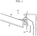
- Fig. 1 is a schematic sectional view of a configuration of a conventional two-sided discharge mechanism 10 based on Japanese Patent Application Laid-Open No. 2000-26002 .
- the conventional two-sided discharge mechanism 10 includes triple rollers 11 for performing a discharge operation and a reversal operation, and a conveyance guide 12 inside the apparatus.
- a sheet 13 discharged by the two-sided discharge mechanism 10 cannot be completely stacked on a discharge tray 14 and remains near the conveyance roller pair.
- the conveyance roller pair rotates in a direction indicated by solid line arrows illustrated in Fig. 1 , which is opposite to a direction of when the discharge operation is performed.
- the sheet 13 receives a conveyance force from the conveyance roller pair, and is conveyed in a direction indicated by a dash-dot line illustrated in Fig. 1 .
- the sheet 13 moves backward to the conveyance path inside the image forming apparatus.
- Occurrence of such a backward movement may cause a phenomenon in which the sheet 13 gets caught by a step portion 15 of the conveyance guide 12 through a path indicated by a dotted line arrow illustrated in the conveyance path, or may cause a sheet-passing failure due to interference with a subsequent sheet (not illustrated) in the conveyance path during continuous printing.
- Japanese Patent Application Laid-Open No. 2012-140200 there is provided a regulation member protruding into the discharge tray area, thereby preventing a stacked sheet from moving backward.
- Japanese Patent Application Laid-Open No. 2012-140200 does not discuss the prevention of a stacked sheet from moving backward when triple rollers are used.
- the regulation member is located much below the nip portion between the discharge roller pair.
- a first exemplary embodiment of the present invention will be described below using a case where the first exemplary embodiment is applied to a laser beam printer as an example of the image forming apparatus.
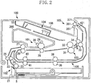
- Fig. 2 is a schematic sectional view of the image forming apparatus 100.
- the image forming apparatus 100 includes an image forming unit 101, a feeding device 102,'a laser scanner unit 104, a fixing device 103, a two-sided discharge device 105, and a discharge tray (stacking portion) 106.
- the feeding device 102 includes a feeding cassette 21, a separation pad 22, and a feeding roller 23, and feeds a stacked sheet S by using the feeding roller 23. Then, the sheet S is further conveyed to a downstream side by a feeding conveyance roller pair formed by feeding conveyance rollers 24 and 25 provided on a downstream side in a conveyance direction.
- the feeding device 102 also includes a registration roller pair formed by registration rollers 26 and 27 for temporarily stopping the sheet S to perform registration between a toner image and the sheet S. For the sheet S conveyed by the feeding conveyance roller pair, positioning and conveyance timing adjustment are performed by the registration roller pair. Then, the sheet S is conveyed to the image forming unit 101.
- the image forming unit 101 includes a process cartridge 200 detachably attached to the main body of the image forming apparatus 100, and the process cartridge 200 includes a photosensitive drum 29 serving as an image bearing member. Further, the image forming unit 101 includes a transfer roller 28 opposing the photosensitive drum 29. Based on image information along with a print command, laser light is applied from the laser scanner unit 104 to a surface of the photosensitive drum 29 which is uniformly charged by a charging device, whereby an electrostatic latent image is formed on the surface of the photosensitive drum 29. By developing the electrostatic latent image using a developing device 30, a toner image is formed on the surface of the photosensitive drum 29.
- the toner image formed on the surface of the photosensitive drum 29 is transferred to the sheet S that has been fed into a nip portion between the photosensitive drum 29 and the transfer roller 28 by the registration roller pair.
- the sheet S to which the image has been transferred is conveyed to the fixing device 103.
- the fixing device 103 includes a heating roller 32, a pressure roller 31 in press contact with the heating roller 32, and fixing conveyance rollers 33 and 34.
- the sheet-S conveyed to the fixing device 103 is guided into a nip portion between the heating roller 32 of the fixing device 103 and the pressure roller 31 in press contact with the heating roller 32.
- the toner image is heated and pressurized to be fixed to the sheet S.
- the sheet S is carried by the fixing conveyance roller pair formed by the fixing conveyance rollers 33 and 34, and is conveyed to the two-sided discharge device 105.
- the two-sided discharge device 105 includes triple rollers having a sheet discharge function and a sheet reversal function, and a flipper (switching portion) 421 for switching a conveyance path.
- the two-sided discharge device 105 selects the discharge operation or the reversal operation according to the print command.
- the discharge operation the sheet S is directly discharged onto the discharge tray 106 and stacked thereon.
- a conveyance direction of the sheet S is reversed with a predetermined timing to feed the sheet S to a reversing conveyance path.
- the sheet S is fed again by a two-sided conveyance roller pair formed by two-sided conveyance rollers 38 and 39, and a re-feed roller pair formed by re-feed rollers 40 and 41.
- the re-fed sheet S passes the image forming unit 101 and the fixing device 103 again, whereby printing is performed on a second side of the sheet S in a similar way to a first side thereof.
- the sheet S on which printing has been performed on a second side is discharged onto the discharge tray 106 by the two-sided discharge device 105, and is stacked thereon.
- Fig. 3A is a schematic perspective view of the two-sided discharge device 105.
- the two-sided discharge device 105 includes triple rollers consisting of a discharge driving roller (first roller) 361, discharge driven rollers (second rollers) 351, and reversal driven rollers (third rollers) 371, and a flipper 421.
- Fig. 11 is a block diagram of a control unit according to the first exemplary embodiment.
- a central processing unit (CPU) 110 is connected to the motor M and the solenoid 90.
- the CPU 110 is connected to a read-only memory (ROM) and a random-access memory (RAM).
- ROM read-only memory
- RAM random-access memory
- the CPU 110 executes a program stored in the ROM.
- the CPU 110, the ROM, and the RAM constitute a control unit.
- the control unit controls the solenoid 90 to switch the drive train that transmits the drive force from the motor M to the discharge driving roller 361.
- the discharge driven roller 351 is provided below the discharge driving roller 361, and is in press contact with the discharge driving roller 361.
- the discharge driven roller 351 and the discharge driving roller 361 form a nip portion, and the discharge driven roller 351 rotates following the rotating discharge driving roller 361.
- the discharge driven roller 351 rotates following the discharge driving roller 361 making normal rotation when discharging the sheet S onto the discharge tray 106.
- the reversal driven roller 371 is provided above the discharge driving roller 361, and is in press contact with the discharge driving roller 361.
- the reversal driven roller 371 and the discharge driving roller 361 form a nip portion, and the reversal driven roller 371 rotates following the rotating discharge driving roller 361.
- the reversal driven roller 371 rotates following the discharge driving roller 361 which makes the reverse rotation and then the normal rotation when the sheet S is to be conveyed to the image forming unit 101 again.
- the flipper 421 is formed by rotation centers 422, a conveyance guide portion 423, connection portions 424, and backward movement prevention portions (regulation portions) 425.
- the flipper 421 is supported so as to be rotatable around the rotation center 422, and is connected to a part of the rotation center 422 and the drive train for the above-mentioned discharge driving roller 361.
- the flipper 421 rotates in response to receiving a rotational drive force from the motor M when the solenoid 90 switches the drive train.
- the rotational direction of the flipper 421 is determined according to the switching of the solenoid 90, similarly to the rotational direction (normal or reverse) of the discharge driving roller 361.
- the configuration according to the first exemplary embodiment is such that when the discharge driving roller 361 rotates clockwise, the flipper 421 also rotates clockwise (makes normal rotation), and when the discharge driving roller 361 rotates counterclockwise, the flipper 421 also rotates counterclockwise (makes reverse rotation). That is, the discharge driving roller 361 and the flipper 421 operate in conjunction with each other to rotate in the same direction.
- the flipper 421 rotates, a contact portion of the flipper 421 comes into contact a part of a member of the image forming apparatus 100, and the flipper 421 is locked at a predetermined position.
- the flipper 421 has two lock positions determined by the normal rotation direction and reverse rotation direction of the discharge driving roller 361. Further, the conveyance guide portion 423 and the backward movement prevention portion 425 of the flipper 421 are connected to each other via the connection portion 424.
- Fig. 3B is a schematic top view of the two-sided discharge device 105. Similarly to Fig. 3A , the conveyance guide and rollers unnecessary for the description are omitted in Fig. 3B .
- the flipper 421 is arranged symmetrically with respect to a center M of a conveyance area L of the sheet S.
- the connection portion 424 is formed at both right and left ends of the flipper 421 and outside the conveyance area L in a longitudinal direction (sheet width direction orthogonal to the conveyance direction) of the maximum size sheet among the sheets that can be conveyed by the image forming apparatus 100.
- the backward movement prevention portion 425 is arranged at both the right and left ends of the flipper 421, and is arranged inside the conveyance area L in the longitudinal direction.
- Fig. 4 is a schematic sectional view of the two-sided discharge device 105.
- the two-sided discharge device 105 has three conveyance areas PA, PB, and PC.
- the conveyance area PA is formed by an inner conveyance guide 43, a conveyance guide surface 423a of the flipper 421, and a middle conveyance guide 44.
- the sheet S on which the discharge operation is performed passes the conveyance area PA.
- the conveyance area PB is a conveyance area on a,downstream side of the triple rollers.
- the sheet S on which the discharge operation and the reversal operation are performed passes in the conveyance area PB.
- the conveyance area PC is formed by the middle conveyance guide 44, the conveyance guide surface 423b of the flipper 421, and an outer conveyance guide 45.
- The.sheet S on which the reversal operation is performed passes in the conveyance area PC.
- Fig. 5 is a schematic sectional view illustrating the discharge operation by the two-sided discharge device 105 when one-sided printing is to be performed.
- the discharge driving roller 361 rotates clockwise, and the discharge driven roller 351 and the reversal driven roller 371 are driven to rotate counterclockwise.
- the flipper 421 operates in conjunction with the clockwise rotation of the discharge driving roller 361 and is locked in a position FA.
- the backward movement prevention portion 425 of the flipper 421 locked in the position FA does not protrude into the conveyance areas PA, PB, or PC of the two-sided discharge device 105, and stays in a retracted position.
- the backward movement prevention portion 425 is located in an allowing position where discharge of the sheet S by the discharge driving roller 361 and the discharge driven roller 351 is allowed.
- the sheet S passes the conveyance area PA, and is conveyed toward the triple rollers by the fixing conveyance roller pair. Then, the sheet S is guided by the conveyance guide surface 423a of the flipper 421 to the nip area formed by the discharge driving roller 361 and the discharge driven roller 351, and is discharged onto the discharge tray 106 by the discharge driving roller 361 and the discharge driven roller 351.
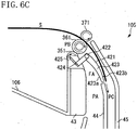
- FIGs. 6A through 6C are schematic sectional views illustrating the reversal operation by the two-sided discharge device 105 when two-sided printing is to be performed.
- the discharge driving roller 361 rotates counterclockwise, and the discharge driven roller 351 and the reversal driven roller 371 are driven to rotate clockwise.
- the flipper 421 rotates in conjunction with the counterclockwise rotation of the discharge driving roller 361, and is locked in a position FB.
- the backward movement prevention portion 425 of the flipper 421 is locked in a position (regulation position) where the backward movement prevention portion 425 protrudes into the conveyance area PB, and blocks the conveyance area PB side of the nip area formed by the discharge driving roller 361 and the discharge driven roller 351.
- the regulation position of the backward movement,prevention portion 425 overlaps a path through which the sheet S discharged by the discharge driving roller 361.and the discharge driven roller .351 passes.
- the backward movement prevention portion 425 blocks the area on the downstream side of the nip portion between the discharge driving roller 361 and the discharge driven roller 351 (the straight line connecting their respective rotation centers), thereby preventing the sheet S from moving backward (from entering the nip portion between the discharge driving roller 361 and the discharge driven roller 351).
- the regulation position of the backward movement prevention portion 425 is a position for blocking the nip portion between the discharge driving roller 361 and the discharge driven roller 351 as viewed from the width direction of the sheet S orthogonal to the discharging direction.
- the backward movement prevention portion 425 is provided so as to be movable between the retracted position and the regulation position, and is moved by the solenoid (moving portion) 90.
- a first sheet S is conveyed by the fixing conveyance roller pair toward the triple rollers after the feeding and printing. Then, the first sheet S is guided to the nip portion between the discharge driving roller 361 and the reversal driven roller 371 by the conveyance guide surface 423b. Then, as illustrated in Fig. 6B , when the first sheet S has been conveyed to a position where the trailing edge of the first sheet S is located on the downstream side of the end portion of the middle conveyance guide 44, the rotation of the discharge driving roller 361 is switched to reverse rotation by the solenoid 90. Then, as illustrated in Fig. 6C , the position of the flipper 421 is also switched to FA in conjunction with the switching of the rotation.
- the first sheet S is conveyed in the reverse direction by the discharge driving roller 361 and the reversal driven roller 371, and is conveyed toward the conveyance area PC for reversal which consists of the middle conveyance guide 44 and the outer conveyance guide 45. Then, the first sheet S passes through the two-sided printing conveyance path, the image forming unit 101, and the fixing device 103 and then is discharged again by the discharge driving roller 361 and the discharge driven roller 351 as illustrated in Fig. 5 .
- the print command from the user requires two-sided printing on a single sheet. Actually, however, there are many cases where the print command requires two-sided printing on a plurality of sheets.
- the first sheet S after printing is performed on a front side, the first sheet S is reversely conveyed to the two-side printing conveyance path, fed again and undergoes printing on a back side, and then discharged.
- a second sheet S is fed by the feeding device 102, and after printing is performed.on a front side, the second sheet S takes the same path as the first sheet S.
- first sheet S and the second sheet S are fed and conveyed with a timing based on a sensor signal so that they do not overlap each other in the conveyance path.
- conveying the first sheet S and the second sheet S with an appropriate timing enables continuous two-sided printing to be performed at a high speed.
- Fig. 7 is a schematic sectional view illustrating the reversal operation and the discharge operation by the two-sided discharge device 105 during continuous two-sided printing.
- the discharge driving roller 361 rotates clockwise
- the discharge driving roller 361 and the discharge driven roller 351 rotate in a direction for discharging the sheet S
- the discharge driving roller 361 and the reversal driven roller 371 rotate in a direction for reversing the sheet S.
- the above-described triple roller configuration can simultaneously perform the operation of discharging the sheet S which has undergone printing and the operation of reversing the sheet S to be reversed, thereby achieving an increase in the speed of the operation to continuously perform printing on both sides.
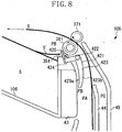
- Fig. 8 is a schematic sectional view illustrating the reversal operation by the two-sided discharge device 105 in a state where there exists a discharged and stacked sheet on the discharge tray 106 during two-sided printing.
- sheets S on which printing has been completed are stacked and accumulated on the discharge tray 106.
- the peripheral environment, and the state of the sheet S itself there may exist a sheet S' that cannot be completely stacked on the discharge tray 106, with the end portion in contact with the discharge driven roller 351.
- the discharge driving roller 361 rotates counterclockwise, causing the sheet S' to be conveyed to the upstream side in the conveyance direction due to the frictional force generated at the position where the sheet S' is in contact with the discharge driven roller 351.
- the position of the flipper 421 is switched from FA to FB at the same time as the discharge driving roller 361 rotates counterclockwise.
- the backward movement prevention portion 425 moves from the retracted position to the regulation position, and protrudes into the conveyance area PB.
- the backward movement prevention portion 425 stops the sheet S' before the sheet S' is conveyed to the upstream side and enters the nip area formed by the discharge driving roller 361 and the discharge driven roller 351, thereby preventing the sheet S' from moving backward.
- the backward movement prevention portion 425 located at the regulation portion blocks the conveyance area PB side of the nip area formed by the discharge driving roller 361 and the discharge driven roller 351 to thereby regulate the position of the sheet S' on the discharge tray 106.
- the backward movement prevention portion 425 blocks the conveyance area PB side of the nip area formed by the discharge driving roller 361 and the discharge driven roller 351, so that the sheet S' on the discharge tray 106 cannot be moved to the nip portion between the discharge driving roller 361 and the discharge driven roller 351.
- the operation of switching the position of the flipper 421 is in conjunction with the rotational direction of the discharge driving roller 361, so that the operation of switching the position of the flipper 421 is performed simultaneously with the conveyance of the sheet S' to the upstream side due to the reverse rotation of the discharge driving roller 361.
- the timing of when the sheet S' is conveyed to the upstream side and the timing of when the backward movement prevention portion 425 changes the position to the position for preventing the backward movement are substantially simultaneous with each other.
- the backward movement prevention portion 425 is on standby near the nip area formed by the discharge driving roller 361 and the discharge driven roller 351, so that the time required to perform the operation of switching to the position FB is short. This can produce the effect of increasing the area where the sheet S' can be prevented from moving backward.
- the position of the flipper 421 is switched at the same time as the rotational direction of the triple rollers is reversed, causing the backward movement prevention portion 425 of the flipper 421 to protrude into the conveyance area PB.
- the configuration has been described in which the flipper 421 and the backward movement prevention portion 425 are integrally provided.
- the backward movement prevention portion 425 and the flipper 421 may be separately provided. For example, they are connected to each other via a link member so that the backward movement prevention portion 425 can operate in conjunction with the flipper 421.
- the configuration has been described in which the switching of the rotational direction of the discharge driving roller 361 and the switching of the position of the flipper 421 are performed by the common solenoid 90.
- the present invention is not limited thereto.
- the above switching operations may be performed by different solenoids. That is, a solenoid for moving the flipper may be separately provided, and be operated with the timing of switching the rotational direction.
- the configuration has been described in which the timing of when the positions of the flipper 421 and the backward movement prevention portion 425 are switched is the same as the timing of when the rotational direction of the discharge driving roller 361 is switched.
- the present invention is not limited thereto. It is desirable for the backward movement prevention portion 425 to be placed at the regulation position a little earlier than the timing of when the rotational direction of the discharge driving roller 361 is switched. However, it is also possible for the backward movement prevention position 425 to be placed at the regulation portion a little later than the timing of when the rotational direction of the discharge driving roller 361 is switched.
- a second exemplary embodiment of the present invention will be described below.
- a basic configuration of the image forming apparatus 100 is similar to that of the first exemplary embodiment, and therefore the components having functions and configurations similar or corresponding to those of the first exemplary embodiment are denoted by the same reference numerals, and a detailed description thereof will be omitted.
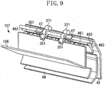
- a two-sided discharge device 107 included in the image forming apparatus 100 according to the second exemplary embodiment will be described with reference to Fig. 9 .
- Fig. 9 is a schematic perspective view of the two-sided discharge device 107.
- the two-sided discharge device 107 includes triple rollers similar to those of the first exemplary embodiment, a flipper 461, and a backward movement prevention member 47.
- the configuration in which the flipper 461 changes its position in conjunction with the rotational direction of the triple rollers is similar to that of the first exemplary embodiment.
- the flipper 461 is rotatably supported by rotation centers 462.
- the backward movement prevention member 47 is supported coaxially with the discharge driving roller 361 and so as to be rotatable. As illustrated in Fig.
- the backward movement prevention member 47 is arranged symmetrically with respect to the center M of the conveyance area.L of the sheet S and within the conveyance area L.
- the backward movement prevention member 47 is fit with the shaft of the discharge driving roller 361.
- the discharge driving roller 361 rotates
- the backward movement prevention member 47 also rotates in the same direction due to friction against the shaft of the discharge driving roller 361.
- the position of the backward movement prevention member 47 is determined and locked. That is, the backward movement prevention member 47 has two lock positions corresponding to the normal rotation and reverse rotation of the discharge driving roller 361.
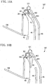
- Fig. 10A is a schematic sectional view illustrating a configuration of the two-sided discharge device 107 when performing discharge operation.
- the discharge driving roller 361 rotates clockwise, and the discharge driven roller 351 and the reversal driven roller 371 are driven to rotate counterclockwise.
- the flipper 461 is locked in a position FC.
- the backward movement prevention member 47 rotates clockwise due to sliding contact with the shaft of the discharge driving roller 361, and comes into contact with a part of the flipper 461, whereby the position thereof is determined. At this time, the backward movement prevention member 47 is locked in a position (retracted position) where the backward movement prevention member 47 does not prevent the sheet S from being conveyed for one-sided printing or two-sided printing.
- Fig. 10B is a schematic sectional view illustrating a configuration of the two-sided discharge device 107 when performing reversal operation.
- the discharge driving roller 361 rotates counterclockwise, and the discharge driven roller 351 and the reversal driven roller 371 are driven to rotate clockwise.
- the flipper 461 is locked in a position FD.
- the backward movement prevention member 47 rotates counterclockwise due to sliding contact with the shaft of the discharge driving roller 361, and comes into contact with a part of the inner conveyance guide 43, whereby its position is determined.
- the backward movement prevention member 47 blocks the nip area formed by the discharge driving roller 361 and the discharge driven roller 351, and is locked at a position (regulation position) where the sheet S can be prevented from moving backward from the conveyance area PB.
- This configuration prevents the sheet S', which cannot be completely stacked on the discharge tray 106 and be in contact with the discharge driven roller 351, from moving backward toward the nip area formed by the discharge driving roller 361 and the discharge driven roller 351.
- the configuration according to the second exemplary embodiment can also prevent the sheet S from moving backward in the area near the nip potion between the discharge roller pair, so that an effect similar to that of the first exemplary embodiment can be achieved without increasing the size of the apparatus.
- the regulation portion is placed in the regulation position while the driving roller is making reverse rotation.
- the regulation portion can block the area on the downstream side of the nip portion between the first and second rollers.
Landscapes
- Engineering & Computer Science (AREA)
- Mechanical Engineering (AREA)
- Physics & Mathematics (AREA)
- General Physics & Mathematics (AREA)
- Separation, Sorting, Adjustment, Or Bending Of Sheets To Be Conveyed (AREA)
- Delivering By Means Of Belts And Rollers (AREA)
- Pile Receivers (AREA)
- Feeding Of Articles By Means Other Than Belts Or Rollers (AREA)
- Paper Feeding For Electrophotography (AREA)
Claims (11)
- Bilderzeugungsvorrichtung, umfassend:eine Bilderzeugungseinrichtung (101), die zum Erzeugen eines Bilds auf einem Bogen (S) ausgebildet ist;einen Stapelabschnitt (106), auf dem der Bogen (S) mit dem durch die Bilderzeugungseinrichtung (101) darauf erzeugten Bild gestapelt werden soll;eine erste Walze (361), die in der Lage ist, sich vorwärts und rückwärts zu drehen,eine zweite Walze (351), die über ein unterhalb eines Drehzentrums der ersten Walze (361) angeordnetes Drehzentrum verfügt und zum Drehen mit der ersten Walze (361) ausgebildet ist, wenn sich die erste Walze (361) vorwärts dreht, wenn der Bogen (S) auf den Stapelabschnitt (106) ausgeworfen werden soll;eine dritte Walze (371), die über ein oberhalb des Drehzentrums der ersten Walze (361) angeordnetes Drehzentrum verfügt und zum Drehen mit der ersten Walze (361) ausgebildet ist, wenn sich die erste Walze (361) rückwärts und anschließend vorwärts dreht, wenn ein Bogen (S), auf dem ein Bild auf einer ersten Seite des Bogens durch die Bilderzeugungseinrichtung (101) erzeugt worden ist, an die Bilderzeugungseinrichtung (101) transportiert werden soll, um ein Bild auf einer zweiten, der ersten Seite gegenüberliegenden Seite des Bogens zu erzeugen; gekennzeichnet durcheinen Regulierabschnitt (425), der derart vorgesehen ist, dass er beweglich ist zwischen einer Regulierposition, bei der ein Eintreten des auf dem Stapelabschnitt gestapelten Bogens in einen Andruckabschnitt zwischen der ersten Walze (361) und der zweiten Walze (351) verhindert wird, und einer Zulassposition, bei der ein Auswerfen des Bogens (S) durch die erste Walze (361) und die zweite Walze (351) zugelassen wird; undeine Bewegungseinrichtung (90), die ausgebildet ist zum Veranlassen, dass der Regulierabschnitt (425) in die Zulassposition gebracht wird, während die erste Walze (361) die Vorwärtsdrehung durchführt und zum Veranlassen, dass der Regulierabschnitt (425) in die Regulierposition gebracht wird, während die erste Walze (361) die Rückwärtsdrehung durchführt.
- Bilderzeugungsvorrichtung nach Anspruch 1, wobei die Regulierposition des Regulierabschnitts (425) eine Position ist, die ausgebildet ist zum Blockieren des Andruckabschnitts zwischen der ersten Walze (361) und der zweiten Walze (351), von einer zur Richtung des Auswerfens des Bogens (S) orthogonalen Bogenbreitenrichtung aus betrachtet.
- Bilderzeugungsvorrichtung nach Anspruch 1, wobei die Regulierposition des Regulierabschnitts (425) eine Position in der Nähe des Andruckabschnitts zwischen der ersten Walze (361) und der zweiten Walze (351) ist.
- Bilderzeugungsvorrichtung nach Anspruch 1, wobei die Regulierposition des Regulierabschnitts (425) eine Position ist, die einen Weg überlappt, durch den der durch die erste Walze (361) und die zweite Walze (351) ausgeworfene Bogen (S) hindurchgeht.
- Bilderzeugungsvorrichtung nach Anspruch 1, ferner umfassend einen Führungsabschnitt (423), der vorgesehen ist, beweglich zu sein zwischen einer ersten Position, bei der der Bogen (S), auf dem das Bild durch die Bilderzeugungseinrichtung (101) erzeugt worden ist, zum Andruckabschnitt zwischen der ersten Walze (361) und der zweiten Walze (351) geführt wird, und einer zweiten Position, bei der der Bogen (S), auf dem das Bild durch die Bilderzeugungseinrichtung (101) erzeugt worden ist, zum Andruckabschnitt zwischen der ersten Walze (361) und der dritten Walze (371) geführt wird.
- Bilderzeugungsvorrichtung nach Anspruch 5, wobei der Führungsabschnitt (423) und der Regulierabschnitt (425) integral miteinander verbunden vorgesehen sind.
- Bilderzeugungsvorrichtung nach Anspruch 5, wobei der Führungsabschnitt (423) und der Regulierabschnitt (425) derart ausgebildet sind, dass sie um dieselbe Drehachse drehbar sind.
- Bilderzeugungsvorrichtung nach Anspruch 6, wobei der Regulierabschnitt (425) mit dem Führungsabschnitt (423) durch einen Verbindungsabschnitt (424) verbunden ist, wobei der Regulierabschnitt (425) und der Verbindungsabschnitt (424) ein L-förmiges Element bilden.
- Bilderzeugungsvorrichtung nach Anspruch 1, ferner umfassend eine Antriebsquelle (M), die ausgebildet ist zum Erzeugen einer Antriebskraft zum Drehen der ersten Walze (361),
wobei die zweite Walze (351) und die dritte Walze (371) jeweils ausgebildet sind, sich zusammen mit der ersten Walze (361) zu drehen. - Bilderzeugungsvorrichtung nach Anspruch 9, ferner umfassend eine Steuereinrichtung (110), die ausgebildet ist zum Umschalten einer Drehrichtung der ersten Walze (361) zwischen einer Vorwärtsdrehrichtung und einer Rückwärtsdrehrichtung,
wobei die Bewegungseinrichtung (90) ausgebildet ist zum Veranlassen, dass der Regulierabschnitt (425) sich in Verbindung mit dem Umschalten der Drehrichtung der ersten Walze (361) durch die Steuereinrichtung (110) bewegt. - Bilderzeugungsvorrichtung nach Anspruch 10, wobei die Steuereinrichtung (110) ausgebildet ist zum Steuern eines Elektromagnets (9), so dass ein Antriebsstrang zum Übertragen der Antriebskraft von der Antriebsquelle (M) zur ersten Walze (361) geschaltet wird.
Applications Claiming Priority (1)
| Application Number | Priority Date | Filing Date | Title |
|---|---|---|---|
| JP2013205133A JP5855066B2 (ja) | 2013-09-30 | 2013-09-30 | 画像形成装置 |
Publications (2)
| Publication Number | Publication Date |
|---|---|
| EP2862829A1 EP2862829A1 (de) | 2015-04-22 |
| EP2862829B1 true EP2862829B1 (de) | 2017-02-08 |
Family
ID=51584963
Family Applications (1)
| Application Number | Title | Priority Date | Filing Date |
|---|---|---|---|
| EP14185219.4A Active EP2862829B1 (de) | 2013-09-30 | 2014-09-17 | Bilderzeugungsvorrichtung |
Country Status (4)
| Country | Link |
|---|---|
| US (1) | US9738479B2 (de) |
| EP (1) | EP2862829B1 (de) |
| JP (1) | JP5855066B2 (de) |
| CN (2) | CN104512747B (de) |
Families Citing this family (6)
| Publication number | Priority date | Publication date | Assignee | Title |
|---|---|---|---|---|
| JP6455655B2 (ja) * | 2014-03-27 | 2019-01-23 | セイコーエプソン株式会社 | 記録装置 |
| US9791814B2 (en) * | 2015-04-09 | 2017-10-17 | Canon Kabushiki Kaisha | Image forming apparatus |
| JP2017007798A (ja) * | 2015-06-22 | 2017-01-12 | 富士ゼロックス株式会社 | 画像形成装置 |
| JP6758857B2 (ja) * | 2016-02-25 | 2020-09-23 | キヤノン株式会社 | シート搬送装置及び画像形成装置 |
| WO2018004561A1 (en) * | 2016-06-29 | 2018-01-04 | Hewlett-Packard Development Company, L.P. | Media diversion apparatus |
| JP6862137B2 (ja) * | 2016-09-30 | 2021-04-21 | キヤノン株式会社 | シート搬送装置、画像形成装置 |
Citations (1)
| Publication number | Priority date | Publication date | Assignee | Title |
|---|---|---|---|---|
| US20090189343A1 (en) * | 2008-01-24 | 2009-07-30 | Tien-Ho Hsu | Paper-feeding mechanism |
Family Cites Families (12)
| Publication number | Priority date | Publication date | Assignee | Title |
|---|---|---|---|---|
| JP3465596B2 (ja) | 1998-07-14 | 2003-11-10 | 松下電器産業株式会社 | 両面印字機構を備えた画像形成装置 |
| JP2004099293A (ja) * | 2002-09-12 | 2004-04-02 | Matsushita Electric Ind Co Ltd | 画像形成装置 |
| JP2007051005A (ja) * | 2005-07-19 | 2007-03-01 | Ricoh Co Ltd | 自動原稿給紙装置及び画像形成装置 |
| TWI294354B (en) * | 2006-08-18 | 2008-03-11 | Primax Electronics Ltd | Automatic sheet feeder |
| TW200817197A (en) * | 2006-10-04 | 2008-04-16 | Asia Optical Co Inc | Dual-surface paper feeding device |
| JP4758945B2 (ja) * | 2007-05-17 | 2011-08-31 | 株式会社リコー | スイッチバック機構および画像形成装置 |
| US7762552B2 (en) * | 2007-10-26 | 2010-07-27 | Lexmark International, Inc. | Movable gate with fluid damper for directing media sheets within an image forming apparatus |
| JP4518159B2 (ja) * | 2008-02-29 | 2010-08-04 | ブラザー工業株式会社 | 原稿搬送装置 |
| JP4502147B2 (ja) * | 2008-02-29 | 2010-07-14 | ブラザー工業株式会社 | 原稿搬送装置 |
| JP5371409B2 (ja) * | 2008-12-17 | 2013-12-18 | キヤノン株式会社 | 画像形成装置 |
| US8328195B2 (en) * | 2010-10-07 | 2012-12-11 | Lexmark International, Inc. | Exit path assembly for an imaging device |
| JP2012140200A (ja) * | 2010-12-28 | 2012-07-26 | Canon Inc | 排出装置及び画像形成装置 |
-
2013
- 2013-09-30 JP JP2013205133A patent/JP5855066B2/ja active Active
-
2014
- 2014-09-17 EP EP14185219.4A patent/EP2862829B1/de active Active
- 2014-09-19 CN CN201410485463.1A patent/CN104512747B/zh active Active
- 2014-09-19 CN CN201710176410.5A patent/CN106896681A/zh active Pending
- 2014-09-25 US US14/497,163 patent/US9738479B2/en active Active
Patent Citations (1)
| Publication number | Priority date | Publication date | Assignee | Title |
|---|---|---|---|---|
| US20090189343A1 (en) * | 2008-01-24 | 2009-07-30 | Tien-Ho Hsu | Paper-feeding mechanism |
Also Published As
| Publication number | Publication date |
|---|---|
| US9738479B2 (en) | 2017-08-22 |
| JP5855066B2 (ja) | 2016-02-09 |
| US20150091239A1 (en) | 2015-04-02 |
| EP2862829A1 (de) | 2015-04-22 |
| JP2015069123A (ja) | 2015-04-13 |
| CN104512747A (zh) | 2015-04-15 |
| CN106896681A (zh) | 2017-06-27 |
| CN104512747B (zh) | 2017-04-26 |
Similar Documents
| Publication | Publication Date | Title |
|---|---|---|
| EP2862829B1 (de) | Bilderzeugungsvorrichtung | |
| US9296585B2 (en) | Sheet conveying apparatus, drive transmission apparatus and image forming apparatus | |
| US9908727B2 (en) | Sheet conveyance apparatus and image forming apparatus | |
| JP6315949B2 (ja) | シート搬送装置、及び、画像形成装置 | |
| US12246941B2 (en) | Sheet feeding device | |
| CN110737182B (zh) | 成像设备 | |
| JP4710430B2 (ja) | シート供給装置及び画像形成装置 | |
| US10564584B2 (en) | Sheet-conveying device, image-forming apparatus, and image-reading apparatus | |
| US10435260B2 (en) | Sheet conveying apparatus, image forming apparatus, and image reading apparatus to change the sheet conveying direction by moving a rotating member that conveys the sheet | |
| JP4475181B2 (ja) | シート供給装置及び画像形成装置 | |
| JP2020055663A (ja) | シート搬送装置及び画像形成装置 | |
| US9885988B2 (en) | Sheet conveying apparatus and image forming apparatus including same | |
| US10087029B2 (en) | Sheet conveyance device, image forming apparatus, and image reading apparatus | |
| JP6862137B2 (ja) | シート搬送装置、画像形成装置 | |
| US10556762B2 (en) | Sheet conveying apparatus, image forming apparatus, and image reading apparatus | |
| JP6316266B2 (ja) | 画像形成装置 | |
| JP5786377B2 (ja) | 転写装置、画像形成装置 | |
| JPH0522540Y2 (de) | ||
| JP2006030268A (ja) | 画像形成装置 | |
| JP2020132285A (ja) | シート折り装置、及び、画像形成システム | |
| WO2017170116A1 (ja) | シート搬送装置、画像形成装置、および画像読取装置 | |
| JP2016003067A (ja) | 用紙搬送装置および画像形成装置 | |
| JP2012185455A (ja) | 転写装置、画像形成装置 |
Legal Events
| Date | Code | Title | Description |
|---|---|---|---|
| PUAI | Public reference made under article 153(3) epc to a published international application that has entered the european phase |
Free format text: ORIGINAL CODE: 0009012 |
|
| 17P | Request for examination filed |
Effective date: 20140917 |
|
| AK | Designated contracting states |
Kind code of ref document: A1 Designated state(s): AL AT BE BG CH CY CZ DE DK EE ES FI FR GB GR HR HU IE IS IT LI LT LU LV MC MK MT NL NO PL PT RO RS SE SI SK SM TR |
|
| AX | Request for extension of the european patent |
Extension state: BA ME |
|
| R17P | Request for examination filed (corrected) |
Effective date: 20151022 |
|
| RBV | Designated contracting states (corrected) |
Designated state(s): AL AT BE BG CH CY CZ DE DK EE ES FI FR GB GR HR HU IE IS IT LI LT LU LV MC MK MT NL NO PL PT RO RS SE SI SK SM TR |
|
| GRAP | Despatch of communication of intention to grant a patent |
Free format text: ORIGINAL CODE: EPIDOSNIGR1 |
|
| RIC1 | Information provided on ipc code assigned before grant |
Ipc: B65H 29/58 20060101ALI20160323BHEP Ipc: B65H 29/14 20060101ALI20160323BHEP Ipc: G03G 15/23 20060101ALI20160323BHEP Ipc: G03G 15/00 20060101ALI20160323BHEP Ipc: B65H 85/00 20060101AFI20160323BHEP |
|
| INTG | Intention to grant announced |
Effective date: 20160411 |
|
| GRAJ | Information related to disapproval of communication of intention to grant by the applicant or resumption of examination proceedings by the epo deleted |
Free format text: ORIGINAL CODE: EPIDOSDIGR1 |
|
| GRAS | Grant fee paid |
Free format text: ORIGINAL CODE: EPIDOSNIGR3 |
|
| GRAP | Despatch of communication of intention to grant a patent |
Free format text: ORIGINAL CODE: EPIDOSNIGR1 |
|
| INTC | Intention to grant announced (deleted) | ||
| RIC1 | Information provided on ipc code assigned before grant |
Ipc: G03G 15/23 20060101ALI20160822BHEP Ipc: B65H 29/14 20060101ALI20160822BHEP Ipc: B65H 85/00 20060101AFI20160822BHEP Ipc: B65H 29/58 20060101ALI20160822BHEP Ipc: G03G 15/00 20060101ALI20160822BHEP |
|
| INTG | Intention to grant announced |
Effective date: 20160908 |
|
| GRAA | (expected) grant |
Free format text: ORIGINAL CODE: 0009210 |
|
| AK | Designated contracting states |
Kind code of ref document: B1 Designated state(s): AL AT BE BG CH CY CZ DE DK EE ES FI FR GB GR HR HU IE IS IT LI LT LU LV MC MK MT NL NO PL PT RO RS SE SI SK SM TR |
|
| REG | Reference to a national code |
Ref country code: GB Ref legal event code: FG4D |
|
| REG | Reference to a national code |
Ref country code: CH Ref legal event code: EP Ref country code: AT Ref legal event code: REF Ref document number: 866771 Country of ref document: AT Kind code of ref document: T Effective date: 20170215 |
|
| REG | Reference to a national code |
Ref country code: IE Ref legal event code: FG4D |
|
| REG | Reference to a national code |
Ref country code: DE Ref legal event code: R096 Ref document number: 602014006692 Country of ref document: DE |
|
| REG | Reference to a national code |
Ref country code: LT Ref legal event code: MG4D |
|
| REG | Reference to a national code |
Ref country code: NL Ref legal event code: MP Effective date: 20170208 |
|
| REG | Reference to a national code |
Ref country code: AT Ref legal event code: MK05 Ref document number: 866771 Country of ref document: AT Kind code of ref document: T Effective date: 20170208 |
|
| PG25 | Lapsed in a contracting state [announced via postgrant information from national office to epo] |
Ref country code: HR Free format text: LAPSE BECAUSE OF FAILURE TO SUBMIT A TRANSLATION OF THE DESCRIPTION OR TO PAY THE FEE WITHIN THE PRESCRIBED TIME-LIMIT Effective date: 20170208 Ref country code: NO Free format text: LAPSE BECAUSE OF FAILURE TO SUBMIT A TRANSLATION OF THE DESCRIPTION OR TO PAY THE FEE WITHIN THE PRESCRIBED TIME-LIMIT Effective date: 20170508 Ref country code: FI Free format text: LAPSE BECAUSE OF FAILURE TO SUBMIT A TRANSLATION OF THE DESCRIPTION OR TO PAY THE FEE WITHIN THE PRESCRIBED TIME-LIMIT Effective date: 20170208 Ref country code: LT Free format text: LAPSE BECAUSE OF FAILURE TO SUBMIT A TRANSLATION OF THE DESCRIPTION OR TO PAY THE FEE WITHIN THE PRESCRIBED TIME-LIMIT Effective date: 20170208 Ref country code: GR Free format text: LAPSE BECAUSE OF FAILURE TO SUBMIT A TRANSLATION OF THE DESCRIPTION OR TO PAY THE FEE WITHIN THE PRESCRIBED TIME-LIMIT Effective date: 20170509 |
|
| PG25 | Lapsed in a contracting state [announced via postgrant information from national office to epo] |
Ref country code: AT Free format text: LAPSE BECAUSE OF FAILURE TO SUBMIT A TRANSLATION OF THE DESCRIPTION OR TO PAY THE FEE WITHIN THE PRESCRIBED TIME-LIMIT Effective date: 20170208 Ref country code: RS Free format text: LAPSE BECAUSE OF FAILURE TO SUBMIT A TRANSLATION OF THE DESCRIPTION OR TO PAY THE FEE WITHIN THE PRESCRIBED TIME-LIMIT Effective date: 20170208 Ref country code: NL Free format text: LAPSE BECAUSE OF FAILURE TO SUBMIT A TRANSLATION OF THE DESCRIPTION OR TO PAY THE FEE WITHIN THE PRESCRIBED TIME-LIMIT Effective date: 20170208 Ref country code: LV Free format text: LAPSE BECAUSE OF FAILURE TO SUBMIT A TRANSLATION OF THE DESCRIPTION OR TO PAY THE FEE WITHIN THE PRESCRIBED TIME-LIMIT Effective date: 20170208 Ref country code: SE Free format text: LAPSE BECAUSE OF FAILURE TO SUBMIT A TRANSLATION OF THE DESCRIPTION OR TO PAY THE FEE WITHIN THE PRESCRIBED TIME-LIMIT Effective date: 20170208 Ref country code: ES Free format text: LAPSE BECAUSE OF FAILURE TO SUBMIT A TRANSLATION OF THE DESCRIPTION OR TO PAY THE FEE WITHIN THE PRESCRIBED TIME-LIMIT Effective date: 20170208 Ref country code: BG Free format text: LAPSE BECAUSE OF FAILURE TO SUBMIT A TRANSLATION OF THE DESCRIPTION OR TO PAY THE FEE WITHIN THE PRESCRIBED TIME-LIMIT Effective date: 20170508 Ref country code: PT Free format text: LAPSE BECAUSE OF FAILURE TO SUBMIT A TRANSLATION OF THE DESCRIPTION OR TO PAY THE FEE WITHIN THE PRESCRIBED TIME-LIMIT Effective date: 20170608 |
|
| PG25 | Lapsed in a contracting state [announced via postgrant information from national office to epo] |
Ref country code: RO Free format text: LAPSE BECAUSE OF FAILURE TO SUBMIT A TRANSLATION OF THE DESCRIPTION OR TO PAY THE FEE WITHIN THE PRESCRIBED TIME-LIMIT Effective date: 20170208 Ref country code: CZ Free format text: LAPSE BECAUSE OF FAILURE TO SUBMIT A TRANSLATION OF THE DESCRIPTION OR TO PAY THE FEE WITHIN THE PRESCRIBED TIME-LIMIT Effective date: 20170208 Ref country code: IT Free format text: LAPSE BECAUSE OF FAILURE TO SUBMIT A TRANSLATION OF THE DESCRIPTION OR TO PAY THE FEE WITHIN THE PRESCRIBED TIME-LIMIT Effective date: 20170208 Ref country code: EE Free format text: LAPSE BECAUSE OF FAILURE TO SUBMIT A TRANSLATION OF THE DESCRIPTION OR TO PAY THE FEE WITHIN THE PRESCRIBED TIME-LIMIT Effective date: 20170208 Ref country code: SK Free format text: LAPSE BECAUSE OF FAILURE TO SUBMIT A TRANSLATION OF THE DESCRIPTION OR TO PAY THE FEE WITHIN THE PRESCRIBED TIME-LIMIT Effective date: 20170208 |
|
| REG | Reference to a national code |
Ref country code: DE Ref legal event code: R097 Ref document number: 602014006692 Country of ref document: DE |
|
| PG25 | Lapsed in a contracting state [announced via postgrant information from national office to epo] |
Ref country code: SM Free format text: LAPSE BECAUSE OF FAILURE TO SUBMIT A TRANSLATION OF THE DESCRIPTION OR TO PAY THE FEE WITHIN THE PRESCRIBED TIME-LIMIT Effective date: 20170208 Ref country code: PL Free format text: LAPSE BECAUSE OF FAILURE TO SUBMIT A TRANSLATION OF THE DESCRIPTION OR TO PAY THE FEE WITHIN THE PRESCRIBED TIME-LIMIT Effective date: 20170208 Ref country code: DK Free format text: LAPSE BECAUSE OF FAILURE TO SUBMIT A TRANSLATION OF THE DESCRIPTION OR TO PAY THE FEE WITHIN THE PRESCRIBED TIME-LIMIT Effective date: 20170208 |
|
| PLBE | No opposition filed within time limit |
Free format text: ORIGINAL CODE: 0009261 |
|
| STAA | Information on the status of an ep patent application or granted ep patent |
Free format text: STATUS: NO OPPOSITION FILED WITHIN TIME LIMIT |
|
| 26N | No opposition filed |
Effective date: 20171109 |
|
| PG25 | Lapsed in a contracting state [announced via postgrant information from national office to epo] |
Ref country code: SI Free format text: LAPSE BECAUSE OF FAILURE TO SUBMIT A TRANSLATION OF THE DESCRIPTION OR TO PAY THE FEE WITHIN THE PRESCRIBED TIME-LIMIT Effective date: 20170208 |
|
| REG | Reference to a national code |
Ref country code: CH Ref legal event code: PL |
|
| PG25 | Lapsed in a contracting state [announced via postgrant information from national office to epo] |
Ref country code: MC Free format text: LAPSE BECAUSE OF FAILURE TO SUBMIT A TRANSLATION OF THE DESCRIPTION OR TO PAY THE FEE WITHIN THE PRESCRIBED TIME-LIMIT Effective date: 20170208 |
|
| REG | Reference to a national code |
Ref country code: IE Ref legal event code: MM4A |
|
| REG | Reference to a national code |
Ref country code: BE Ref legal event code: MM Effective date: 20170930 |
|
| PG25 | Lapsed in a contracting state [announced via postgrant information from national office to epo] |
Ref country code: LU Free format text: LAPSE BECAUSE OF NON-PAYMENT OF DUE FEES Effective date: 20170917 |
|
| REG | Reference to a national code |
Ref country code: FR Ref legal event code: ST Effective date: 20180531 |
|
| PG25 | Lapsed in a contracting state [announced via postgrant information from national office to epo] |
Ref country code: CH Free format text: LAPSE BECAUSE OF NON-PAYMENT OF DUE FEES Effective date: 20170930 Ref country code: LI Free format text: LAPSE BECAUSE OF NON-PAYMENT OF DUE FEES Effective date: 20170930 Ref country code: IE Free format text: LAPSE BECAUSE OF NON-PAYMENT OF DUE FEES Effective date: 20170917 |
|
| PG25 | Lapsed in a contracting state [announced via postgrant information from national office to epo] |
Ref country code: BE Free format text: LAPSE BECAUSE OF NON-PAYMENT OF DUE FEES Effective date: 20170930 Ref country code: FR Free format text: LAPSE BECAUSE OF NON-PAYMENT OF DUE FEES Effective date: 20171002 |
|
| PG25 | Lapsed in a contracting state [announced via postgrant information from national office to epo] |
Ref country code: MT Free format text: LAPSE BECAUSE OF NON-PAYMENT OF DUE FEES Effective date: 20170917 |
|
| PG25 | Lapsed in a contracting state [announced via postgrant information from national office to epo] |
Ref country code: HU Free format text: LAPSE BECAUSE OF FAILURE TO SUBMIT A TRANSLATION OF THE DESCRIPTION OR TO PAY THE FEE WITHIN THE PRESCRIBED TIME-LIMIT; INVALID AB INITIO Effective date: 20140917 |
|
| PG25 | Lapsed in a contracting state [announced via postgrant information from national office to epo] |
Ref country code: CY Free format text: LAPSE BECAUSE OF FAILURE TO SUBMIT A TRANSLATION OF THE DESCRIPTION OR TO PAY THE FEE WITHIN THE PRESCRIBED TIME-LIMIT Effective date: 20170208 |
|
| PG25 | Lapsed in a contracting state [announced via postgrant information from national office to epo] |
Ref country code: MK Free format text: LAPSE BECAUSE OF FAILURE TO SUBMIT A TRANSLATION OF THE DESCRIPTION OR TO PAY THE FEE WITHIN THE PRESCRIBED TIME-LIMIT Effective date: 20170208 |
|
| PG25 | Lapsed in a contracting state [announced via postgrant information from national office to epo] |
Ref country code: TR Free format text: LAPSE BECAUSE OF FAILURE TO SUBMIT A TRANSLATION OF THE DESCRIPTION OR TO PAY THE FEE WITHIN THE PRESCRIBED TIME-LIMIT Effective date: 20170208 |
|
| PG25 | Lapsed in a contracting state [announced via postgrant information from national office to epo] |
Ref country code: AL Free format text: LAPSE BECAUSE OF FAILURE TO SUBMIT A TRANSLATION OF THE DESCRIPTION OR TO PAY THE FEE WITHIN THE PRESCRIBED TIME-LIMIT Effective date: 20170208 Ref country code: IS Free format text: LAPSE BECAUSE OF FAILURE TO SUBMIT A TRANSLATION OF THE DESCRIPTION OR TO PAY THE FEE WITHIN THE PRESCRIBED TIME-LIMIT Effective date: 20170608 |
|
| PGFP | Annual fee paid to national office [announced via postgrant information from national office to epo] |
Ref country code: DE Payment date: 20250820 Year of fee payment: 12 |
|
| PGFP | Annual fee paid to national office [announced via postgrant information from national office to epo] |
Ref country code: GB Payment date: 20250820 Year of fee payment: 12 |