EP2862678A2 - Lehrsystem und Lehrmethode - Google Patents
Lehrsystem und Lehrmethode Download PDFInfo
- Publication number
- EP2862678A2 EP2862678A2 EP20140186103 EP14186103A EP2862678A2 EP 2862678 A2 EP2862678 A2 EP 2862678A2 EP 20140186103 EP20140186103 EP 20140186103 EP 14186103 A EP14186103 A EP 14186103A EP 2862678 A2 EP2862678 A2 EP 2862678A2
- Authority
- EP
- European Patent Office
- Prior art keywords
- robot
- teaching
- projection plane
- unit
- work line
- Prior art date
- Legal status (The legal status is an assumption and is not a legal conclusion. Google has not performed a legal analysis and makes no representation as to the accuracy of the status listed.)
- Withdrawn
Links
Images





Classifications
-
- B—PERFORMING OPERATIONS; TRANSPORTING
- B25—HAND TOOLS; PORTABLE POWER-DRIVEN TOOLS; MANIPULATORS
- B25J—MANIPULATORS; CHAMBERS PROVIDED WITH MANIPULATION DEVICES
- B25J9/00—Program-controlled manipulators
- B25J9/16—Program controls
- B25J9/1628—Program controls characterised by the control loop
- B25J9/163—Program controls characterised by the control loop learning, adaptive, model based, rule based expert control
-
- B—PERFORMING OPERATIONS; TRANSPORTING
- B25—HAND TOOLS; PORTABLE POWER-DRIVEN TOOLS; MANIPULATORS
- B25J—MANIPULATORS; CHAMBERS PROVIDED WITH MANIPULATION DEVICES
- B25J11/00—Manipulators not otherwise provided for
- B25J11/0075—Manipulators for painting or coating
-
- B—PERFORMING OPERATIONS; TRANSPORTING
- B25—HAND TOOLS; PORTABLE POWER-DRIVEN TOOLS; MANIPULATORS
- B25J—MANIPULATORS; CHAMBERS PROVIDED WITH MANIPULATION DEVICES
- B25J9/00—Program-controlled manipulators
- B25J9/16—Program controls
- B25J9/1656—Program controls characterised by programming, planning systems for manipulators
- B25J9/1671—Program controls characterised by programming, planning systems for manipulators characterised by simulation, either to verify existing program or to create and verify new program, CAD/CAM oriented, graphic oriented programming systems
-
- B—PERFORMING OPERATIONS; TRANSPORTING
- B25—HAND TOOLS; PORTABLE POWER-DRIVEN TOOLS; MANIPULATORS
- B25J—MANIPULATORS; CHAMBERS PROVIDED WITH MANIPULATION DEVICES
- B25J9/00—Program-controlled manipulators
- B25J9/16—Program controls
- B25J9/1679—Program controls characterised by the tasks executed
- B25J9/1684—Tracking a line or surface by means of sensors
-
- G—PHYSICS
- G06—COMPUTING OR CALCULATING; COUNTING
- G06N—COMPUTING ARRANGEMENTS BASED ON SPECIFIC COMPUTATIONAL MODELS
- G06N20/00—Machine learning
-
- G—PHYSICS
- G05—CONTROLLING; REGULATING
- G05B—CONTROL OR REGULATING SYSTEMS IN GENERAL; FUNCTIONAL ELEMENTS OF SUCH SYSTEMS; MONITORING OR TESTING ARRANGEMENTS FOR SUCH SYSTEMS OR ELEMENTS
- G05B2219/00—Program-control systems
- G05B2219/30—Nc systems
- G05B2219/35—Nc in input of data, input till input file format
- G05B2219/35115—Project 3-D surface on 2-D plane, define grid in plane
-
- G—PHYSICS
- G05—CONTROLLING; REGULATING
- G05B—CONTROL OR REGULATING SYSTEMS IN GENERAL; FUNCTIONAL ELEMENTS OF SUCH SYSTEMS; MONITORING OR TESTING ARRANGEMENTS FOR SUCH SYSTEMS OR ELEMENTS
- G05B2219/00—Program-control systems
- G05B2219/30—Nc systems
- G05B2219/36—Nc in input of data, input key till input tape
- G05B2219/36017—Graphic assisted robot programming, display projection of surface
-
- G—PHYSICS
- G05—CONTROLLING; REGULATING
- G05B—CONTROL OR REGULATING SYSTEMS IN GENERAL; FUNCTIONAL ELEMENTS OF SUCH SYSTEMS; MONITORING OR TESTING ARRANGEMENTS FOR SUCH SYSTEMS OR ELEMENTS
- G05B2219/00—Program-control systems
- G05B2219/30—Nc systems
- G05B2219/45—Nc applications
- G05B2219/45013—Spraying, coating, painting
-
- G—PHYSICS
- G05—CONTROLLING; REGULATING
- G05B—CONTROL OR REGULATING SYSTEMS IN GENERAL; FUNCTIONAL ELEMENTS OF SUCH SYSTEMS; MONITORING OR TESTING ARRANGEMENTS FOR SUCH SYSTEMS OR ELEMENTS
- G05B2219/00—Program-control systems
- G05B2219/30—Nc systems
- G05B2219/45—Nc applications
- G05B2219/45065—Sealing, painting robot
-
- Y—GENERAL TAGGING OF NEW TECHNOLOGICAL DEVELOPMENTS; GENERAL TAGGING OF CROSS-SECTIONAL TECHNOLOGIES SPANNING OVER SEVERAL SECTIONS OF THE IPC; TECHNICAL SUBJECTS COVERED BY FORMER USPC CROSS-REFERENCE ART COLLECTIONS [XRACs] AND DIGESTS
- Y10—TECHNICAL SUBJECTS COVERED BY FORMER USPC
- Y10S—TECHNICAL SUBJECTS COVERED BY FORMER USPC CROSS-REFERENCE ART COLLECTIONS [XRACs] AND DIGESTS
- Y10S901/00—Robots
- Y10S901/27—Arm part
- Y10S901/28—Joint
-
- Y—GENERAL TAGGING OF NEW TECHNOLOGICAL DEVELOPMENTS; GENERAL TAGGING OF CROSS-SECTIONAL TECHNOLOGIES SPANNING OVER SEVERAL SECTIONS OF THE IPC; TECHNICAL SUBJECTS COVERED BY FORMER USPC CROSS-REFERENCE ART COLLECTIONS [XRACs] AND DIGESTS
- Y10—TECHNICAL SUBJECTS COVERED BY FORMER USPC
- Y10S—TECHNICAL SUBJECTS COVERED BY FORMER USPC CROSS-REFERENCE ART COLLECTIONS [XRACs] AND DIGESTS
- Y10S901/00—Robots
- Y10S901/30—End effector
- Y10S901/41—Tool
- Y10S901/43—Spray painting or coating
-
- Y—GENERAL TAGGING OF NEW TECHNOLOGICAL DEVELOPMENTS; GENERAL TAGGING OF CROSS-SECTIONAL TECHNOLOGIES SPANNING OVER SEVERAL SECTIONS OF THE IPC; TECHNICAL SUBJECTS COVERED BY FORMER USPC CROSS-REFERENCE ART COLLECTIONS [XRACs] AND DIGESTS
- Y10—TECHNICAL SUBJECTS COVERED BY FORMER USPC
- Y10S—TECHNICAL SUBJECTS COVERED BY FORMER USPC CROSS-REFERENCE ART COLLECTIONS [XRACs] AND DIGESTS
- Y10S901/00—Robots
- Y10S901/46—Sensing device
- Y10S901/47—Optical
-
- Y—GENERAL TAGGING OF NEW TECHNOLOGICAL DEVELOPMENTS; GENERAL TAGGING OF CROSS-SECTIONAL TECHNOLOGIES SPANNING OVER SEVERAL SECTIONS OF THE IPC; TECHNICAL SUBJECTS COVERED BY FORMER USPC CROSS-REFERENCE ART COLLECTIONS [XRACs] AND DIGESTS
- Y10—TECHNICAL SUBJECTS COVERED BY FORMER USPC
- Y10S—TECHNICAL SUBJECTS COVERED BY FORMER USPC CROSS-REFERENCE ART COLLECTIONS [XRACs] AND DIGESTS
- Y10S901/00—Robots
- Y10S901/50—Miscellaneous
Definitions
- the embodiment discussed herein is directed to a teaching system and a teaching method.
- Such teaching systems enable an operator to create teaching data without actually operating the robot.
- TEACHING METHOD OF COATING ROBOT AND COATING METHOD disclosed in Japanese Patent Application laid-open No. 2011-005612 , for example, is a method for creating teaching data for a coating robot that coats a car body or the like off-line.
- the conventional technology however, has room for improvement in terms of facilitating teaching on the coating use.
- teaching for the coating robot is carried out by setting a plurality of target points on a coating surface and causing a coating gun attached to the coating robot to trace a locus obtained by connecting the target points.
- the coating surface has a large area like a car body. This makes the process complicated. Furthermore, the coating surface is likely to include a curved surface and an uneven surface. This makes it difficult for the operator to visually set the target points appropriately on the three-dimensional model displayed on the display device.
- an aspect of an embodiment aims to provide a teaching system and a teaching method that can facilitate teaching on surface processing.
- a teaching system includes an image generating unit, a projecting unit, a work line generating unit, an arithmetic unit, and a job generating unit.
- the image generating unit generates a virtual image including a robot and a workpiece having a processed surface to be processed by the robot.
- the projecting unit generates a projection plane orthogonal to a normal direction of a desired point on the processed surface selected on the virtual image and projects the processed surface onto the projection plane.
- the work line generating unit generates a work line serving as a group of target points for the robot based on a setting content received via the projection plane.
- the arithmetic unit calculates a teaching value including a position and a posture of the robot at each point of the target points.
- the job generating unit generates a job program for operating the robot in an actual configuration based on the teaching value calculated by the arithmetic unit.
- An aspect of the embodiment can facilitate teaching on surface processing.
- the following describes a teaching system that displays a graphic image of a three-dimensional model of a robot on a display unit, such as a display.
- the graphic image of a three-dimensional model may be hereinafter referred to as a "virtual image”.
- the present invention is not limited thereto.
- the present invention is also applicable to a processing robot system including a processing robot that can perform surface processing, such as blasting, polishing, and padding.
- the coating robot is hereinafter referred to as a "robot”, and the coating robot system is referred to as a "robot system”.
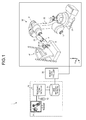
- Fig. 1 is a schematic of an entire configuration of a robot system 1 including a teaching system 10 according to an embodiment.
- the robot system 1 includes the teaching system 10, a robot controller 20, and a robot 30.
- the teaching system 10 includes a teaching controller 11, a display unit 12, an operating unit 13, and a job information database (DB) 14.
- DB job information database
- the teaching controller 11 is a controller that collectively controls the teaching system 10 and includes an arithmetic processing unit and a memory, for example.
- the teaching controller 11 is connected to various types of devices of the teaching system 10, such as the display unit 12, in a manner capable of transmitting information.
- the teaching controller 11 outputs a virtual image including the robot 30 whose operation is subjected to a simulation operation to the display unit 12 based on an operation performed by an operator with the operating unit 13.
- the virtual image further includes a workpiece W having a processed surface to be processed by the robot 30.
- the processed surface is a coated surface of the workpiece W
- the workpiece W is a car door panel.
- the teaching controller 11 generates a job program for operating the robot 30 from the virtual image based on an operation performed by the operator with the operating unit 13 and registers the job program in the job information DB 14.
- the display unit 12 is what is called a display device, such as a display.
- the operating unit 13 is an input device, such as a mouse.
- the operating unit 13 is not necessarily provided as a hardware component and may be a software component, such as a touch key displayed on a touch panel display.
- the job information DB 14 registers therein information on teaching, such as the job program for operating the robot 30 and a "teaching point" included in the job program.
- the "teaching point” is information indicating a target position through which each joint of the robot 30 is caused to pass to reproductively operate the robot 30.
- the "teaching point” is stored as a pulse value of each encoder provided to a servomotor that drives each shaft of the robot 30, for example. Because the robot 30 is operated based on information on a plurality of teaching points, the job information DB 14 stores therein a plurality of teaching points in association with each motion (job) of the robot 30.
- the job program of the robot 30 includes combined information of a plurality of teaching points, an instruction for an interpolation operation between the teaching points, and an operation instruction for an end effector, for example.
- the job information DB 14 stores therein information on teaching points for each job program of the robot 30. To reproductively operate the robot 30, for example, the robot 30 is operated based on the job program.
- the job information DB 14 is connected to the robot controller 20 serving as a controller that controls an operation of the actual robot 30 in a manner capable of transmitting information.
- the robot controller 20 controls various types of operations of the robot 30 based on the job program registered in the job information DB 14.
- the job information DB 14 (teaching system 10) is connected to the robot controller 20 in Fig. 1 .
- the job information DB 14 (teaching system 10) is not necessarily connected to the robot controller 20 as long as the job program generated by the teaching system 10 can be stored in a predetermined storage unit (not illustrated) in the robot controller 20.
- the job program By copying the job program generated by the teaching system 10 to a medium, such as a universal serial bus (USB) memory, and connecting the medium to the robot controller 20, for example, the job program may be stored in the predetermined storage unit (not illustrated) in the robot controller 20 with a predetermined operation.
- a medium such as a universal serial bus (USB) memory
- job information DB 14 is separated from the teaching controller 11 in Fig. 1 to facilitate the explanation, the job information DB 14 may be stored in a storage unit in the teaching controller 11.
- the robot 30 includes a base 31, a first arm 32, a second arm 33, a flange 34, and an end effector 35.
- the base 31 is fixed to a floor surface or the like and supports the base end of the first arm 32 rotatably about an axis S (refer to the arrow about the axis S in Fig. 1 ).
- the base 31 supports the base end of the first arm 32 rotatably about an axis L (refer to the arrow about the axis L in Fig. 1 ).
- the base end of the first arm 32 is supported by the base 31 as described above, and the tip of the first arm 32 supports the base end of the second arm 33 rotatably about an axis U (refer to the arrow about the axis U in Fig. 1 ).
- the base end of the second arm 33 is supported by the first arm 32 as described above, and the tip of the second arm 33 supports the base end of the flange 34 rotatably about an axis B (refer to the arrow about the axis B in Fig. 1 ). Furthermore, the second arm 33 is provided rotatably about an axis R (refer to the arrow about the axis R in Fig. 1 ).
- the base end of the flange 34 is supported by the second arm 33 as described above, and the tip of the flange 34 supports the base end of the end effector 35 rotatably about an axis T (refer to the arrow about the axis T in Fig. 1 ).
- the end effector 35 is a coating gun, and the base end thereof is supported by the flange 34 as described above.
- Joints of the robot 30 are each provided with a driving source, such as a servomotor.
- the driving sources drive the respective joints of the robot 30 based on an operation instruction transmitted from the robot controller 20.
- FIG. 2 is a block diagram of the configuration of the teaching system 10 according to the embodiment. Fig. 2 illustrates only the components required for the explanation of the teaching system 10 and does not illustrate typical components.
- the following mainly describes the internal configuration of the teaching controller 11 with reference to Fig. 2 .
- the following may simply explain the display unit 12, the operating unit 13, and the job information DB 14, which are already explained with reference to Fig. 1 .
- the teaching controller 11 includes a control unit 111 and a storage unit 112.
- the control unit 111 includes an image generating unit 111a, a display control unit 111b, an operation receiving unit 111c, a projecting unit 111d, a work line generating unit 111e, a teaching value arithmetic unit 111f, and a job generating unit 111g.
- the teaching value arithmetic unit 111f is an example of an arithmetic unit.
- the storage unit 112 stores therein model information 112a and teaching point information 112b.
- the image generating unit 111a generates a virtual image including the robot 30 and the workpiece W based on the model information 112a.
- Means for generating a virtual image in the claims corresponds to the image generating unit 111a.
- the model information 112a includes drawing information defined in advance for each type of the robot 30 and the workpiece W.
- the image generating unit 111a outputs the generated virtual image to the display control unit 111b.
- the display control unit 111b displays the virtual image received from the image generating unit 111a on the display unit 12.
- the operation receiving unit 111c receives an input operation input by the operator with the operating unit 13. If the input operation relates to generation of a work line, which is a group of target points for the robot 30, the operation receiving unit 111c notifies the projecting unit 111d and the work line generating unit 111e of the received input operation.
- Examples of the input operation relating to generation of a work line include an operation to determine a coating surface of the workpiece W on the virtual image and select a desired point on the coating surface and an operation to input various types of setting contents for generation of the work line. The specific contents of these operations will be described later with reference to Fig. 5A and figures subsequent thereto.
- the operation receiving unit 111c notifies the job generating unit 111g of the received input operation.
- the input operation to instruct generation of a job is an operation of clicking an operating component, such as a "job generation" button, displayed on the display unit 12, for example.
- the projecting unit 111d receives, from the operation receiving unit 111c, the notification that an operation to determine a coating surface of the workpiece W on the virtual image and select a desired point on the coating surface is received, the projecting unit 111d generates a projection plane orthogonal to the normal direction of the point and projects the coating surface onto the projection plane.
- Means for projecting a processed surface in the claims corresponds to the projecting unit 111d.
- the projecting unit 111d outputs the projection plane to the image generating unit 111a.
- the image generating unit 111a regenerates a virtual image including the projection plane and displays the virtual image on the display unit 12 via the display control unit 111b.
- Figs. 3A and 3B are the first and the second views, respectively, for explaining a projection plane PP.
- a part of the workpiece W having the shape illustrated in Figs. 3A and 3B is determined to be a coating surface P on the virtual image.
- the projection plane PP is generated as a virtual plane orthogonal to the normal direction of a point P1, which is a desired point on the coating surface P selected (hereinafter, which may be referred to as "picked") on the virtual image.
- the projection plane PP is generated in a substantially rectangular shape covering at least the entire coating surface P when the coating surface P is viewed in the normal direction of the point P1.
- the projecting unit 111d when the desired point P1 on the coating surface P is picked by the operator on the virtual image, the projecting unit 111d generates the projection plane PP using the normal direction of the point P1 as a viewpoint direction. The projecting unit 111d then two-dimensionally projects the coating surface P onto the projection plane PP.
- the present embodiment two-dimensionally projects the coating surface P onto the projection plane PP generated at a point of view in the normal direction of the optionally picked point P1. This can simplify the shape of the coating surface P and facilitate the operator's grasping the shape at a desired point of view.
- the operator performs an operation to input various types of setting contents used to generate a work line, which is a group of target points for the robot 30, while viewing the coating surface P projected onto the projection plane PP, that is, via the projection plane PP. This enables the operator to visually set the target points appropriately.
- the work line generating unit 111e generates a work line based on the setting contents received from the operator via the projection plane PP.
- Means for generating a work line in the claims corresponds to the work line generating unit 111e.
- the work line generating unit 111e receives, from the operation receiving unit 111c, the notification that an operation to input various types of setting contents used to generate a work line is received, the work line generating unit 111e extracts each point of the target points for the robot 30 based on the setting contents, thereby generating a work line serving as a group of target points.
- the work line generating unit 111e outputs the generated work line to the image generating unit 111a.
- the image generating unit 111a regenerates a virtual image including the work line and displays the virtual image on the display unit 12 via the display control unit 111b.
- the teaching value arithmetic unit 111f calculates a teaching value including the position and the posture of the robot 30 at each point of the target points based on the work line generated by the work line generating unit 111e. Means for calculating a teaching value in the claims corresponds to the teaching value arithmetic unit 111f.
- the teaching value arithmetic unit 111f registers the calculated teaching value corresponding to each point of the target points in the teaching point information 112b.
- the teaching value arithmetic unit 111f calculates the teaching value for each joint shaft included in the robot 30 by inverse kinematics calculation, for example.
- the inverse kinematics calculation is performed on each point in a manner suitable for coating with the coordinate value of each point of the target points in a three-dimensional coordinate system serving as the position of the end effector 35 arranged at the tip of the robot 30 and with a direction orthogonal to the vector direction of the work line on each point serving as the posture of the end effector 35.
- the explanation starts with an example of the virtual image generated by the image generating unit 111a and displayed on the display unit 12 via the display control unit 111b with reference to Fig. 4 .
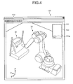
- Fig. 4 is a schematic of an example of the virtual image displayed on the display unit 12. While a robot and a workpiece illustrated in Fig. 4 and figures subsequent thereto are images on the virtual image displayed on the display unit 12, reference numerals "30" and "W" are assigned to the robot and the workpiece, respectively, similarly to the description above. As illustrated in Fig. 4 , the virtual image including the robot 30 and the workpiece W is displayed on a display window 120, which is one of display areas on the display unit 12.
- GUI graphical user interface
- a rectangular coordinate system is displayed at the lower left part of the virtual image area 121 and serves as a reference coordinate system in the virtual image.
- the rectangular coordinate system corresponds to the three-dimensional coordinate system described above and serves as a reference in the horizontal direction and vertical direction. Specifically, a direction parallel to the X-Y plane specified by the X-axis and the Y-axis of the reference coordinate system corresponds to the horizontal direction, whereas a direction parallel to the Z-axis of the reference coordinate system corresponds to the vertical direction.
- the operator operates the GUI widget and operable components on the virtual image (e.g., the coating surface P of the workpiece W), thereby performing an instruction operation on the teaching system 10.
- the teaching system 10 can drive each joint of the robot 30 in the virtual image on the display unit 12.
- the teaching system 10 can change the point of view by determining the direction to view the virtual image in display and zoom in and out the display.
- the teaching system 10 can also derive the position of each joint of the robot 30 when the tip of the end effector 35 (coating gun in the present embodiment) reaches a specific point in the virtual image by inverse kinematics calculation.
- the teaching system 10 can generate and display the virtual image of the robot 30 whose tip of the end effector 35 reaches the specific point.
- the teaching system 10 can read the teaching points and the job program registered in the job information DB 14 based on the instruction operation performed by the operator.
- the teaching system 10 can display the virtual image of the robot 30 whose tip of the end effector 35 reaches a specific teaching point and reproduce a series of operation of the robot 30 performed by the job program on the display unit 12.
- the "job generation” button may be provided to the button 123a in the dialog box 123, for example.
- Figs. 5A and 5B are the first and the second views, respectively, for explaining the operation to determine the coating surface P.
- the dialog box 123 displays a group of operating components used to determine the coating surface P as illustrated in Fig. 5A . If the operator turns ON a "surface pick" check box, which is one of the operating components, it is possible to select each surface to be coated on the workpiece W.
- a plurality of surfaces can be selected.
- the operator consecutively clicks surfaces P'1 and P'2 with a cursor C (refer to the arrow 501 in Fig. 5A ) while pressing a predetermined key as illustrated in Fig. 5A .
- both surfaces P'1 and P'2 are selected.
- connection button which is one of the operating components.
- the surfaces are connected and considered as one coating surface.
- the operator specifies an opposite angle of the rectangle on the virtual image using the operating unit 13 to surround an unnecessary portion in the trimming tool T1, for example, thereby removing the portion (e.g., unnecessary portions E1 and E2 in Fig. 5B ).
- the operator turns ON an "optional" check box, it is possible to remove an area optionally surrounded with the cursor C, which is not illustrated.
- the operator presses an "OK" button, thereby determining the coating surface P to be coated. Determining the coating surface P with such a simple operation makes it possible to facilitate the operator's teaching on the surface processing.
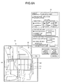
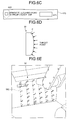
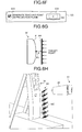
- Figs. 6A to 6H are the first to the eighth views, respectively, for explaining an operation to generate a work line.
- the dialog box 123 displays a group of operating components used to generate a work line as illustrated in Fig. 6A . If the operator turns ON a "projection direction specification" check box, which is one of the operating components, it is possible to pick the desired point P1 on the coating surface P.
- the projecting unit 111d After the point P1 is picked, the projecting unit 111d generates the projection plane PP orthogonal to the normal direction of the point P1 and projects the coating surface P onto the projection plane PP as described above. To facilitate the operator's viewing the projection plane PP, it is preferable to display the projection plane PP while automatically change the point of view for the virtual image such that the normal direction of the point P1 is substantially orthogonal to the planar direction of the display, for example.
- the operator can set the direction of coating to the vertical or the horizontal direction using the radio buttons in the "direction”.
- the operator can determine a position on the coating surface P to start the coating using the radio buttons in the "cutting start position”.
- coating setting the operator can select whether to coat the coating surface P by specifying the coating pitch with a numerical value or the number of times of reciprocation of the coating gun. Furthermore, the operator can input the value of the coating pitch or the number of times of reciprocation (the number of divisions).
- the operator can determine how much to offset a coating start position from the end of the coating surface P and how much to offset a coating end position from the end of the coating surface P.
- Fig. 6A illustrates an example of display in which the "direction” is set to “vertical”, the “cutting start position” is set to “upper left”, and the “coating pitch” is set to "60.0" mm.
- This configuration can display the work line WC to be actually generated to the operator in a readily graspable manner, thereby facilitating teaching on the surface processing.
- the projecting unit 111d can rotate the projection plane PP about the normal direction of the point P1 based on setting contents in an operating component "rotation angle specification" in the dialog box 123, for example (refer to the arrow 601 in Fig. 6B ).
- a part other than the projection plane PP such as the coating surface P, the robot 30, and the workpiece W, relatively with respect to the projection plane PP.
- This configuration can display the work line WC to the operator in the same direction without changing the direction of the work line WC, thereby facilitating the operator's grasping the work line WC. In other words, this can facilitate teaching on the surface processing.
- the direction and the size of the projection plane PP is sequentially recalculated, and thus the projection plane PP is redisplayed on the display unit 12 by the image generating unit 111a and the display control unit 111b.
- the work line generating unit 111e can select whether to generate the work line WC on the projection plane PP or the actual coating surface P based on the setting contents in the operating components in the dialog box 123, for example.
- the work line generating unit 111e generates the work line WC such that the group of target points is arranged on the actual coating surface P of the workpiece W as illustrated in Fig. 6D .
- Fig. 6E illustrates an example of a drawing image on the virtual image when the group of target points is arranged on the actual coating surface P.
- the position of the arrows on the work line WC indicates the position of the respective target points, and the direction thereof indicates the direction of the coating gun corresponding to the end effector 35.
- the number assigned to the arrows indicates the order of movement of the coating gun.
- the work line generating unit 111e generates the work line WC such that the group of target points is arranged not on the actual coating surface P of the workpiece W but on the projection plane PP as illustrated in Fig. 6G .
- the projection plane PP is generated at a position away from the point P1 in the normal direction by the distance "d".
- Fig. 6H illustrates an example of a drawing image on the virtual image when the group of target points is arranged on the projection plane PP.
- the present embodiment can select whether to generate the work line WC on the projection plane PP or the actual coating surface P. This can facilitate appropriate teaching depending on the shape of the actual coating surface P and the like.
- the operator may select the pattern to generate the work line WC on the projection plane PP.
- the operator may select the pattern to generate the work line WC on the actual coating surface P.
- this can facilitate the operator's teaching depending on the coating quality derived based on the shape of the coating surface P or the like with a simple operation.
- the job generating unit 111g of the teaching controller 11 When receiving an input operation to instruct generation of a job from the operation receiving unit 111c, the job generating unit 111g generates a job program for operating the actual robot 30 based on the teaching point information 112b and registers the job program in the job information DB 14. Means for generating a job program in the claims corresponds to the job generating unit 111g.
- the storage unit 112 is a storage device, such as a hard disk drive and a non-volatile memory, and stores therein the model information 112a and the teaching point information 112b. Because the contents of the model information 112a and the teaching point information 112b are already explained, the description thereof is omitted.
- the teaching controller 11 generates the virtual image including the robot 30 based on the model information 112a registered in advance, for example.
- the teaching controller 11 may sequentially acquire information required to generate an image from a host device connected thereto in a manner communicable with each other.
- a teaching system includes an image generating unit, a projecting unit, a work line generating unit, an arithmetic unit, and a job generating unit.
- the image generating unit generates a virtual image including a robot and a workpiece having a processed surface to be processed by the robot.
- the projecting unit generates a projection plane orthogonal to a normal direction of a desired point on the processed surface selected on the virtual image and projects the processed surface onto the projection plane.
- the work line generating unit generates a work line serving as a group of target points for the robot based on setting contents received via the projection plane.
- the arithmetic unit calculates a teaching value including a position and a posture of the robot at each point of the target points.
- the job generating unit generates a job program for operating the robot in an actual configuration based on the teaching value calculated by the arithmetic unit.
- the teaching system according to the embodiment can facilitate teaching on surface processing.
- the projecting unit generates one projection plane orthogonal to the normal direction of a desired point on the coating surface, for example.
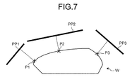
- the projecting unit may generate a plurality of projection planes for the respective desired points.
- Fig. 7 is a view for explaining projection planes PP1 to PP3 according to the modification. As illustrated in Fig. 7 , a plurality of desired points P1 to P3 may be selected on the coating surface of the workpiece W, and the projection planes PP1 to PP3 may be generated for the points P1 to P3, respectively.
- the robot is a six-axis single-arm robot in the embodiment above, the number of axes and arms is not limited thereto.
- the display unit may be a touch panel supporting what is called multi-touch, and the input operation may include a multi-touch operation performed on the touch panel, for example.
Landscapes
- Engineering & Computer Science (AREA)
- Robotics (AREA)
- Mechanical Engineering (AREA)
- Software Systems (AREA)
- Theoretical Computer Science (AREA)
- Computer Vision & Pattern Recognition (AREA)
- Evolutionary Computation (AREA)
- Medical Informatics (AREA)
- Data Mining & Analysis (AREA)
- Physics & Mathematics (AREA)
- Computing Systems (AREA)
- General Engineering & Computer Science (AREA)
- General Physics & Mathematics (AREA)
- Mathematical Physics (AREA)
- Artificial Intelligence (AREA)
- Numerical Control (AREA)
- Manipulator (AREA)
Applications Claiming Priority (1)
| Application Number | Priority Date | Filing Date | Title |
|---|---|---|---|
| JP2013216511A JP5975010B2 (ja) | 2013-10-17 | 2013-10-17 | ティーチングシステムおよびティーチング方法 |
Publications (2)
| Publication Number | Publication Date |
|---|---|
| EP2862678A2 true EP2862678A2 (de) | 2015-04-22 |
| EP2862678A3 EP2862678A3 (de) | 2015-05-13 |
Family
ID=51726300
Family Applications (1)
| Application Number | Title | Priority Date | Filing Date |
|---|---|---|---|
| EP20140186103 Withdrawn EP2862678A3 (de) | 2013-10-17 | 2014-09-24 | Lehrsystem und Lehrmethode |
Country Status (5)
| Country | Link |
|---|---|
| US (1) | US9311608B2 (de) |
| EP (1) | EP2862678A3 (de) |
| JP (1) | JP5975010B2 (de) |
| KR (1) | KR20150044812A (de) |
| CN (1) | CN104552298A (de) |
Cited By (5)
| Publication number | Priority date | Publication date | Assignee | Title |
|---|---|---|---|---|
| CN105033996A (zh) * | 2015-05-22 | 2015-11-11 | 苏州法鲁克自动化设备有限公司 | 基于手推示教式五轴水平关节机器人的控制系统 |
| WO2017187105A1 (fr) * | 2016-04-29 | 2017-11-02 | Antoine Rennuit | Automate pour le traitement d'une surface |
| CN109129558A (zh) * | 2017-11-22 | 2019-01-04 | 北京芯合科技有限公司 | 一种控制机械臂末端执行空间曲线动作的方法 |
| EP3369534A4 (de) * | 2015-10-30 | 2019-04-03 | Kabushiki Kaisha Yaskawa Denki | Roboterlehrvorrichtung, computerprogramm und roboterlehrverfahren |
| DE112021000968B4 (de) * | 2020-05-15 | 2025-08-14 | Fanuc Corporation | Einlernsystem und Einlernverfahren für Laserbearbeitung |
Families Citing this family (24)
| Publication number | Priority date | Publication date | Assignee | Title |
|---|---|---|---|---|
| US10048851B2 (en) * | 2015-03-19 | 2018-08-14 | Denso Wave Incorporated | Apparatus for operating robots |
| JP6631279B2 (ja) * | 2015-03-19 | 2020-01-15 | 株式会社デンソーウェーブ | ロボット操作装置、ロボット操作プログラム |
| CN105945942A (zh) * | 2016-04-05 | 2016-09-21 | 广东工业大学 | 一种机器人离线编程系统及方法 |
| KR102686459B1 (ko) | 2016-12-06 | 2024-07-18 | 한화로보틱스 주식회사 | 경계면 설정 장치 및 방법 |
| WO2018183961A1 (en) | 2017-03-31 | 2018-10-04 | Canvas Construction, Inc. | Automated drywall sanding system and method |
| WO2019060920A1 (en) | 2017-09-25 | 2019-03-28 | Canvas Construction, Inc. | AUTOMATED WALL FINISHING SYSTEM AND METHOD |
| JP7035555B2 (ja) * | 2018-01-23 | 2022-03-15 | セイコーエプソン株式会社 | 教示装置、及びシステム |
| WO2020046963A1 (en) * | 2018-08-27 | 2020-03-05 | Ascend Robotics LLC | Automated construction robot systems and methods |
| JP6838017B2 (ja) * | 2018-08-31 | 2021-03-03 | ファナック株式会社 | レーザ加工のための教示装置、教示方法、及び教示プログラム |
| JP6841805B2 (ja) * | 2018-10-03 | 2021-03-10 | ファナック株式会社 | ロボット教示装置、ロボット教示方法、及び動作命令を記憶する方法 |
| US11724404B2 (en) | 2019-02-21 | 2023-08-15 | Canvas Construction, Inc. | Surface finish quality evaluation system and method |
| JP7396872B2 (ja) * | 2019-11-22 | 2023-12-12 | ファナック株式会社 | 拡張現実を用いたシミュレーション装置及びロボットシステム |
| JP7395990B2 (ja) * | 2019-11-25 | 2023-12-12 | セイコーエプソン株式会社 | 教示装置、制御方法および教示プログラム |
| JP7522396B2 (ja) * | 2019-11-28 | 2024-07-25 | 国立大学法人 熊本大学 | 設計装置、設計方法及びプログラム |
| US20220410394A1 (en) * | 2019-12-09 | 2022-12-29 | Augmentus Pte. Ltd. | Method and system for programming a robot |
| DE112021003687T5 (de) * | 2020-07-10 | 2023-07-06 | Fanuc Corporation | Lernvorrichtung und lernverfahren zum laserbearbeiten |
| JP7491115B2 (ja) * | 2020-07-22 | 2024-05-28 | セイコーエプソン株式会社 | ロボットの教示制御方法、ロボットシステム、及び、コンピュータープログラム |
| CN112486094B (zh) * | 2020-11-30 | 2022-07-05 | 哈尔滨工业大学(威海) | 复杂曲面侧铣加工的刀具优化和加工轨迹生成方法 |
| JP2023004016A (ja) * | 2021-06-25 | 2023-01-17 | セイコーエプソン株式会社 | プログラム作成装置およびプログラム |
| US20250026004A1 (en) * | 2021-12-07 | 2025-01-23 | Kawasaki Jukogyo Kabushiki Kaisha | Teaching system, robot system, teaching method for robot, and teaching program for robot |
| WO2023106353A1 (ja) * | 2021-12-07 | 2023-06-15 | 川崎重工業株式会社 | 教示システム、ロボットシステム、ロボットの教示方法及びロボットの教示プログラム |
| US12539607B2 (en) * | 2022-01-19 | 2026-02-03 | Intrinsic Innovation Llc | Robot programming |
| JP7745150B2 (ja) * | 2022-02-10 | 2025-09-29 | スズキ株式会社 | 塗装ロボットの動作プログラム生成システム、動作プログラム生成方法、および教示点生成装置 |
| CN116619409B (zh) * | 2023-05-31 | 2026-02-17 | 成都飞机工业(集团)有限责任公司 | 一种机器人涂胶方法、装置、存储介质及电子设备 |
Citations (1)
| Publication number | Priority date | Publication date | Assignee | Title |
|---|---|---|---|---|
| JP2011005612A (ja) | 2009-06-29 | 2011-01-13 | Daihatsu Motor Co Ltd | 塗装ロボットの教示方法および塗装方法 |
Family Cites Families (17)
| Publication number | Priority date | Publication date | Assignee | Title |
|---|---|---|---|---|
| JPS60195615A (ja) * | 1984-03-16 | 1985-10-04 | Hitachi Ltd | 多関節ロボツトの姿勢教示方法 |
| JP3448951B2 (ja) | 1993-08-25 | 2003-09-22 | マツダ株式会社 | 塗装における塗装タレの評価方法及び塗装制御装置 |
| JP3367321B2 (ja) * | 1996-03-06 | 2003-01-14 | 株式会社豊田自動織機 | 産業用ロボットの教示データ作成方法、産業用ロボットの教示データ作成装置、及び、産業用ロボットシステム |
| JP3343682B2 (ja) * | 1999-06-18 | 2002-11-11 | 独立行政法人産業技術総合研究所 | ロボット動作教示装置および動作教示方法 |
| NO317898B1 (no) * | 2002-05-24 | 2004-12-27 | Abb Research Ltd | Fremgangsmate og system for a programmere en industrirobot |
| JP2004094399A (ja) * | 2002-08-29 | 2004-03-25 | Mitsubishi Heavy Ind Ltd | 多関節マニピュレータの制御方法及びその制御プログラム、並びにその制御システム |
| US7236854B2 (en) * | 2004-01-05 | 2007-06-26 | Abb Research Ltd. | Method and a system for programming an industrial robot |
| JP2006048244A (ja) * | 2004-08-02 | 2006-02-16 | Fanuc Ltd | 加工プログラム作成装置 |
| DE102005060967B4 (de) * | 2005-12-20 | 2007-10-25 | Technische Universität München | Verfahren und Vorrichtung zum Einrichten einer Bahnkurve einer Robotervorrichtung |
| JP4238256B2 (ja) * | 2006-06-06 | 2009-03-18 | ファナック株式会社 | ロボットシミュレーション装置 |
| JP5126076B2 (ja) * | 2009-01-08 | 2013-01-23 | 富士通株式会社 | 位置測定装置、成膜方法並びに成膜プログラム及び成膜装置 |
| CA2799042A1 (en) * | 2010-05-12 | 2011-11-17 | Avant-Garde Technologie Cfma Inc. | Method and system for generating instructions for an automated machine |
| JP2011251395A (ja) * | 2010-06-04 | 2011-12-15 | Takamaru Kogyo Kk | ロボット教示システム |
| EP2433716A1 (de) * | 2010-09-22 | 2012-03-28 | Hexagon Technology Center GmbH | Oberflächenspritzvorrichtung mit einem Kontrollmechanismus für die Düse und einer entsprechenden Methode |
| DE102013112516B4 (de) | 2012-11-14 | 2022-07-07 | Fanuc Robotics America Corporation | Lehrpunktprogramm-Auswahlverfahren für Robotersimulator |
| US20140220249A1 (en) * | 2013-02-07 | 2014-08-07 | Abb Technology Ag | Interlaced painting |
| JP5729404B2 (ja) * | 2013-02-21 | 2015-06-03 | 株式会社安川電機 | ティーチングシステムおよびティーチング方法 |
-
2013
- 2013-10-17 JP JP2013216511A patent/JP5975010B2/ja active Active
-
2014
- 2014-08-12 CN CN201410393750.XA patent/CN104552298A/zh active Pending
- 2014-09-12 US US14/484,270 patent/US9311608B2/en not_active Expired - Fee Related
- 2014-09-24 EP EP20140186103 patent/EP2862678A3/de not_active Withdrawn
- 2014-10-14 KR KR20140138259A patent/KR20150044812A/ko not_active Ceased
Patent Citations (1)
| Publication number | Priority date | Publication date | Assignee | Title |
|---|---|---|---|---|
| JP2011005612A (ja) | 2009-06-29 | 2011-01-13 | Daihatsu Motor Co Ltd | 塗装ロボットの教示方法および塗装方法 |
Cited By (8)
| Publication number | Priority date | Publication date | Assignee | Title |
|---|---|---|---|---|
| CN105033996A (zh) * | 2015-05-22 | 2015-11-11 | 苏州法鲁克自动化设备有限公司 | 基于手推示教式五轴水平关节机器人的控制系统 |
| EP3369534A4 (de) * | 2015-10-30 | 2019-04-03 | Kabushiki Kaisha Yaskawa Denki | Roboterlehrvorrichtung, computerprogramm und roboterlehrverfahren |
| US11092950B2 (en) | 2015-10-30 | 2021-08-17 | Kabushiki Kaisha Yaskawa Denki | Robot teaching device, and robot teaching method |
| WO2017187105A1 (fr) * | 2016-04-29 | 2017-11-02 | Antoine Rennuit | Automate pour le traitement d'une surface |
| FR3050672A1 (fr) * | 2016-04-29 | 2017-11-03 | Antoine Rennuit | Automate pour le traitement d'une surface |
| US11369983B2 (en) | 2016-04-29 | 2022-06-28 | Les Companions | Automaton for treating a surface |
| CN109129558A (zh) * | 2017-11-22 | 2019-01-04 | 北京芯合科技有限公司 | 一种控制机械臂末端执行空间曲线动作的方法 |
| DE112021000968B4 (de) * | 2020-05-15 | 2025-08-14 | Fanuc Corporation | Einlernsystem und Einlernverfahren für Laserbearbeitung |
Also Published As
| Publication number | Publication date |
|---|---|
| KR20150044812A (ko) | 2015-04-27 |
| EP2862678A3 (de) | 2015-05-13 |
| US9311608B2 (en) | 2016-04-12 |
| US20150112482A1 (en) | 2015-04-23 |
| JP5975010B2 (ja) | 2016-08-23 |
| CN104552298A (zh) | 2015-04-29 |
| JP2015077661A (ja) | 2015-04-23 |
Similar Documents
| Publication | Publication Date | Title |
|---|---|---|
| US9311608B2 (en) | Teaching system and teaching method | |
| CN104002297B (zh) | 示教系统、示教方法及机器人系统 | |
| CN110977931B (zh) | 使用了增强现实和混合现实的机器人控制装置及显示装置 | |
| US9984178B2 (en) | Robot simulator, robot teaching apparatus and robot teaching method | |
| EP2993542B1 (de) | Lehrsystem, robotersystem und lehrmethode | |
| US20150151431A1 (en) | Robot simulator, robot teaching device, and robot teaching method | |
| JP6683671B2 (ja) | ジョグ座標系を設定するロボットの制御装置 | |
| US10534876B2 (en) | Simulation device and simulation method that carry out simulation of operation of robot system, and recording medium that records computer program | |
| KR20160002329A (ko) | 로봇 시뮬레이터 및 로봇 시뮬레이터의 파일 생성 방법 | |
| CN114905487B (zh) | 示教装置、示教方法以及记录介质 | |
| JP5813931B2 (ja) | 教示データの修正システム | |
| JP5272447B2 (ja) | 数値制御機械の動作シミュレータ | |
| CN108145702B (zh) | 用于设置边界面的设备和设置边界面的方法 | |
| JPH06102919A (ja) | ロボット軌道を教示するための方法 | |
| CN110883499A (zh) | 应用于多轴机床的加工倾斜平面的程序生成方法及设备 | |
| JPH06134684A (ja) | ロボット軌道を教示するための方法 | |
| JP2015100874A (ja) | ロボットシステム | |
| JP2019084609A (ja) | ロボット制御装置、ロボットおよびロボットシステム | |
| JPH09141579A (ja) | ロボットの教示装置及びその教示方法 |
Legal Events
| Date | Code | Title | Description |
|---|---|---|---|
| PUAL | Search report despatched |
Free format text: ORIGINAL CODE: 0009013 |
|
| PUAI | Public reference made under article 153(3) epc to a published international application that has entered the european phase |
Free format text: ORIGINAL CODE: 0009012 |
|
| 17P | Request for examination filed |
Effective date: 20140924 |
|
| AK | Designated contracting states |
Kind code of ref document: A2 Designated state(s): AL AT BE BG CH CY CZ DE DK EE ES FI FR GB GR HR HU IE IS IT LI LT LU LV MC MK MT NL NO PL PT RO RS SE SI SK SM TR |
|
| AX | Request for extension of the european patent |
Extension state: BA ME |
|
| AK | Designated contracting states |
Kind code of ref document: A3 Designated state(s): AL AT BE BG CH CY CZ DE DK EE ES FI FR GB GR HR HU IE IS IT LI LT LU LV MC MK MT NL NO PL PT RO RS SE SI SK SM TR |
|
| AX | Request for extension of the european patent |
Extension state: BA ME |
|
| RIC1 | Information provided on ipc code assigned before grant |
Ipc: B25J 9/16 20060101AFI20150409BHEP |
|
| R17P | Request for examination filed (corrected) |
Effective date: 20151008 |
|
| RBV | Designated contracting states (corrected) |
Designated state(s): AL AT BE BG CH CY CZ DE DK EE ES FI FR GB GR HR HU IE IS IT LI LT LU LV MC MK MT NL NO PL PT RO RS SE SI SK SM TR |
|
| STAA | Information on the status of an ep patent application or granted ep patent |
Free format text: STATUS: THE APPLICATION HAS BEEN WITHDRAWN |
|
| 18W | Application withdrawn |
Effective date: 20160718 |