EP2862610A1 - Filtre en nid d'abeilles - Google Patents
Filtre en nid d'abeilles Download PDFInfo
- Publication number
- EP2862610A1 EP2862610A1 EP20130803946 EP13803946A EP2862610A1 EP 2862610 A1 EP2862610 A1 EP 2862610A1 EP 20130803946 EP20130803946 EP 20130803946 EP 13803946 A EP13803946 A EP 13803946A EP 2862610 A1 EP2862610 A1 EP 2862610A1
- Authority
- EP
- European Patent Office
- Prior art keywords
- exhaust gas
- cell
- cells
- gas introduction
- cross
- Prior art date
- Legal status (The legal status is an assumption and is not a legal conclusion. Google has not performed a legal analysis and makes no representation as to the accuracy of the status listed.)
- Granted
Links
Images


Classifications
-
- B—PERFORMING OPERATIONS; TRANSPORTING
- B01—PHYSICAL OR CHEMICAL PROCESSES OR APPARATUS IN GENERAL
- B01D—SEPARATION
- B01D46/00—Filters or filtering processes specially modified for separating dispersed particles from gases or vapours
- B01D46/10—Particle separators, e.g. dust precipitators, using filter plates, sheets or pads having plane surfaces
-
- B—PERFORMING OPERATIONS; TRANSPORTING
- B01—PHYSICAL OR CHEMICAL PROCESSES OR APPARATUS IN GENERAL
- B01D—SEPARATION
- B01D39/00—Filtering material for liquid or gaseous fluids
- B01D39/14—Other self-supporting filtering material ; Other filtering material
- B01D39/20—Other self-supporting filtering material ; Other filtering material of inorganic material, e.g. asbestos paper, metallic filtering material of non-woven wires
- B01D39/2068—Other inorganic materials, e.g. ceramics
-
- B—PERFORMING OPERATIONS; TRANSPORTING
- B01—PHYSICAL OR CHEMICAL PROCESSES OR APPARATUS IN GENERAL
- B01D—SEPARATION
- B01D46/00—Filters or filtering processes specially modified for separating dispersed particles from gases or vapours
- B01D46/24—Particle separators, e.g. dust precipitators, using rigid hollow filter bodies
- B01D46/2403—Particle separators, e.g. dust precipitators, using rigid hollow filter bodies characterised by the physical shape or structure of the filtering element
- B01D46/2418—Honeycomb filters
- B01D46/2425—Honeycomb filters characterized by parameters related to the physical properties of the honeycomb structure material
- B01D46/2429—Honeycomb filters characterized by parameters related to the physical properties of the honeycomb structure material of the honeycomb walls or cells
-
- B—PERFORMING OPERATIONS; TRANSPORTING
- B01—PHYSICAL OR CHEMICAL PROCESSES OR APPARATUS IN GENERAL
- B01D—SEPARATION
- B01D46/00—Filters or filtering processes specially modified for separating dispersed particles from gases or vapours
- B01D46/24—Particle separators, e.g. dust precipitators, using rigid hollow filter bodies
- B01D46/2403—Particle separators, e.g. dust precipitators, using rigid hollow filter bodies characterised by the physical shape or structure of the filtering element
- B01D46/2418—Honeycomb filters
- B01D46/2425—Honeycomb filters characterized by parameters related to the physical properties of the honeycomb structure material
- B01D46/24491—Porosity
-
- B—PERFORMING OPERATIONS; TRANSPORTING
- B01—PHYSICAL OR CHEMICAL PROCESSES OR APPARATUS IN GENERAL
- B01D—SEPARATION
- B01D46/00—Filters or filtering processes specially modified for separating dispersed particles from gases or vapours
- B01D46/24—Particle separators, e.g. dust precipitators, using rigid hollow filter bodies
- B01D46/2403—Particle separators, e.g. dust precipitators, using rigid hollow filter bodies characterised by the physical shape or structure of the filtering element
- B01D46/2418—Honeycomb filters
- B01D46/2425—Honeycomb filters characterized by parameters related to the physical properties of the honeycomb structure material
- B01D46/24492—Pore diameter
-
- B—PERFORMING OPERATIONS; TRANSPORTING
- B01—PHYSICAL OR CHEMICAL PROCESSES OR APPARATUS IN GENERAL
- B01D—SEPARATION
- B01D46/00—Filters or filtering processes specially modified for separating dispersed particles from gases or vapours
- B01D46/24—Particle separators, e.g. dust precipitators, using rigid hollow filter bodies
- B01D46/2403—Particle separators, e.g. dust precipitators, using rigid hollow filter bodies characterised by the physical shape or structure of the filtering element
- B01D46/2418—Honeycomb filters
- B01D46/2451—Honeycomb filters characterized by the geometrical structure, shape, pattern or configuration or parameters related to the geometry of the structure
- B01D46/2462—Honeycomb filters characterized by the geometrical structure, shape, pattern or configuration or parameters related to the geometry of the structure the outer peripheral sealing
-
- B—PERFORMING OPERATIONS; TRANSPORTING
- B01—PHYSICAL OR CHEMICAL PROCESSES OR APPARATUS IN GENERAL
- B01D—SEPARATION
- B01D46/00—Filters or filtering processes specially modified for separating dispersed particles from gases or vapours
- B01D46/24—Particle separators, e.g. dust precipitators, using rigid hollow filter bodies
- B01D46/2403—Particle separators, e.g. dust precipitators, using rigid hollow filter bodies characterised by the physical shape or structure of the filtering element
- B01D46/2418—Honeycomb filters
- B01D46/2451—Honeycomb filters characterized by the geometrical structure, shape, pattern or configuration or parameters related to the geometry of the structure
- B01D46/247—Honeycomb filters characterized by the geometrical structure, shape, pattern or configuration or parameters related to the geometry of the structure of the cells
-
- B—PERFORMING OPERATIONS; TRANSPORTING
- B01—PHYSICAL OR CHEMICAL PROCESSES OR APPARATUS IN GENERAL
- B01D—SEPARATION
- B01D46/00—Filters or filtering processes specially modified for separating dispersed particles from gases or vapours
- B01D46/24—Particle separators, e.g. dust precipitators, using rigid hollow filter bodies
- B01D46/2403—Particle separators, e.g. dust precipitators, using rigid hollow filter bodies characterised by the physical shape or structure of the filtering element
- B01D46/2418—Honeycomb filters
- B01D46/2451—Honeycomb filters characterized by the geometrical structure, shape, pattern or configuration or parameters related to the geometry of the structure
- B01D46/2474—Honeycomb filters characterized by the geometrical structure, shape, pattern or configuration or parameters related to the geometry of the structure of the walls along the length of the honeycomb
-
- B—PERFORMING OPERATIONS; TRANSPORTING
- B01—PHYSICAL OR CHEMICAL PROCESSES OR APPARATUS IN GENERAL
- B01D—SEPARATION
- B01D46/00—Filters or filtering processes specially modified for separating dispersed particles from gases or vapours
- B01D46/24—Particle separators, e.g. dust precipitators, using rigid hollow filter bodies
- B01D46/2403—Particle separators, e.g. dust precipitators, using rigid hollow filter bodies characterised by the physical shape or structure of the filtering element
- B01D46/2418—Honeycomb filters
- B01D46/2451—Honeycomb filters characterized by the geometrical structure, shape, pattern or configuration or parameters related to the geometry of the structure
- B01D46/2478—Structures comprising honeycomb segments
-
- B—PERFORMING OPERATIONS; TRANSPORTING
- B01—PHYSICAL OR CHEMICAL PROCESSES OR APPARATUS IN GENERAL
- B01D—SEPARATION
- B01D46/00—Filters or filtering processes specially modified for separating dispersed particles from gases or vapours
- B01D46/24—Particle separators, e.g. dust precipitators, using rigid hollow filter bodies
- B01D46/2403—Particle separators, e.g. dust precipitators, using rigid hollow filter bodies characterised by the physical shape or structure of the filtering element
- B01D46/2418—Honeycomb filters
- B01D46/2451—Honeycomb filters characterized by the geometrical structure, shape, pattern or configuration or parameters related to the geometry of the structure
- B01D46/2482—Thickness, height, width, length or diameter
-
- B—PERFORMING OPERATIONS; TRANSPORTING
- B01—PHYSICAL OR CHEMICAL PROCESSES OR APPARATUS IN GENERAL
- B01D—SEPARATION
- B01D46/00—Filters or filtering processes specially modified for separating dispersed particles from gases or vapours
- B01D46/24—Particle separators, e.g. dust precipitators, using rigid hollow filter bodies
- B01D46/2403—Particle separators, e.g. dust precipitators, using rigid hollow filter bodies characterised by the physical shape or structure of the filtering element
- B01D46/2418—Honeycomb filters
- B01D46/2451—Honeycomb filters characterized by the geometrical structure, shape, pattern or configuration or parameters related to the geometry of the structure
- B01D46/2484—Cell density, area or aspect ratio
-
- B—PERFORMING OPERATIONS; TRANSPORTING
- B01—PHYSICAL OR CHEMICAL PROCESSES OR APPARATUS IN GENERAL
- B01D—SEPARATION
- B01D46/00—Filters or filtering processes specially modified for separating dispersed particles from gases or vapours
- B01D46/24—Particle separators, e.g. dust precipitators, using rigid hollow filter bodies
- B01D46/2403—Particle separators, e.g. dust precipitators, using rigid hollow filter bodies characterised by the physical shape or structure of the filtering element
- B01D46/2418—Honeycomb filters
- B01D46/2451—Honeycomb filters characterized by the geometrical structure, shape, pattern or configuration or parameters related to the geometry of the structure
- B01D46/2486—Honeycomb filters characterized by the geometrical structure, shape, pattern or configuration or parameters related to the geometry of the structure characterised by the shapes or configurations
- B01D46/249—Quadrangular e.g. square or diamond
-
- B—PERFORMING OPERATIONS; TRANSPORTING
- B01—PHYSICAL OR CHEMICAL PROCESSES OR APPARATUS IN GENERAL
- B01D—SEPARATION
- B01D46/00—Filters or filtering processes specially modified for separating dispersed particles from gases or vapours
- B01D46/24—Particle separators, e.g. dust precipitators, using rigid hollow filter bodies
- B01D46/2403—Particle separators, e.g. dust precipitators, using rigid hollow filter bodies characterised by the physical shape or structure of the filtering element
- B01D46/2418—Honeycomb filters
- B01D46/2451—Honeycomb filters characterized by the geometrical structure, shape, pattern or configuration or parameters related to the geometry of the structure
- B01D46/2486—Honeycomb filters characterized by the geometrical structure, shape, pattern or configuration or parameters related to the geometry of the structure characterised by the shapes or configurations
- B01D46/2494—Octagonal
-
- F—MECHANICAL ENGINEERING; LIGHTING; HEATING; WEAPONS; BLASTING
- F01—MACHINES OR ENGINES IN GENERAL; ENGINE PLANTS IN GENERAL; STEAM ENGINES
- F01N—GAS-FLOW SILENCERS OR EXHAUST APPARATUS FOR MACHINES OR ENGINES IN GENERAL; GAS-FLOW SILENCERS OR EXHAUST APPARATUS FOR INTERNAL COMBUSTION ENGINES
- F01N3/00—Exhaust or silencing apparatus having means for purifying, rendering innocuous, or otherwise treating exhaust
- F01N3/02—Exhaust or silencing apparatus having means for purifying, rendering innocuous, or otherwise treating exhaust for cooling, or for removing solid constituents of, exhaust
- F01N3/021—Exhaust or silencing apparatus having means for purifying, rendering innocuous, or otherwise treating exhaust for cooling, or for removing solid constituents of, exhaust by means of filters
- F01N3/022—Exhaust or silencing apparatus having means for purifying, rendering innocuous, or otherwise treating exhaust for cooling, or for removing solid constituents of, exhaust by means of filters characterised by specially adapted filtering structure, e.g. honeycomb, mesh or fibrous
- F01N3/0222—Exhaust or silencing apparatus having means for purifying, rendering innocuous, or otherwise treating exhaust for cooling, or for removing solid constituents of, exhaust by means of filters characterised by specially adapted filtering structure, e.g. honeycomb, mesh or fibrous the structure being monolithic, e.g. honeycombs
-
- F—MECHANICAL ENGINEERING; LIGHTING; HEATING; WEAPONS; BLASTING
- F01—MACHINES OR ENGINES IN GENERAL; ENGINE PLANTS IN GENERAL; STEAM ENGINES
- F01N—GAS-FLOW SILENCERS OR EXHAUST APPARATUS FOR MACHINES OR ENGINES IN GENERAL; GAS-FLOW SILENCERS OR EXHAUST APPARATUS FOR INTERNAL COMBUSTION ENGINES
- F01N2330/00—Structure of catalyst support or particle filter
- F01N2330/30—Honeycomb supports characterised by their structural details
- F01N2330/34—Honeycomb supports characterised by their structural details with flow channels of polygonal cross section
-
- F—MECHANICAL ENGINEERING; LIGHTING; HEATING; WEAPONS; BLASTING
- F01—MACHINES OR ENGINES IN GENERAL; ENGINE PLANTS IN GENERAL; STEAM ENGINES
- F01N—GAS-FLOW SILENCERS OR EXHAUST APPARATUS FOR MACHINES OR ENGINES IN GENERAL; GAS-FLOW SILENCERS OR EXHAUST APPARATUS FOR INTERNAL COMBUSTION ENGINES
- F01N2330/00—Structure of catalyst support or particle filter
- F01N2330/30—Honeycomb supports characterised by their structural details
- F01N2330/48—Honeycomb supports characterised by their structural details characterised by the number of flow passages, e.g. cell density
-
- Y—GENERAL TAGGING OF NEW TECHNOLOGICAL DEVELOPMENTS; GENERAL TAGGING OF CROSS-SECTIONAL TECHNOLOGIES SPANNING OVER SEVERAL SECTIONS OF THE IPC; TECHNICAL SUBJECTS COVERED BY FORMER USPC CROSS-REFERENCE ART COLLECTIONS [XRACs] AND DIGESTS
- Y02—TECHNOLOGIES OR APPLICATIONS FOR MITIGATION OR ADAPTATION AGAINST CLIMATE CHANGE
- Y02T—CLIMATE CHANGE MITIGATION TECHNOLOGIES RELATED TO TRANSPORTATION
- Y02T10/00—Road transport of goods or passengers
- Y02T10/10—Internal combustion engine [ICE] based vehicles
- Y02T10/12—Improving ICE efficiencies
Definitions
- the present invention relates to a honeycomb filter.
- Exhaust gas discharged from an internal combustion engine such as a diesel engine contains particulates such as soot (hereinafter also referred to as PM).
- PM particulates such as soot
- the PM adversely affects the environment and human bodies, which has been a recent issue.
- exhaust gas contains toxic gas components such as CO, HC, and NOx, there has also been a concern about the effect of the toxic gas components on the environment and human bodies.
- honeycomb structure a honeycomb filter formed of porous ceramics such as cordierite and silicon carbide
- exhaust gas purifying apparatuses Such a honeycomb filter is connected to an internal combustion engine to capture PM in exhaust gas or to convert toxic gas components such as CO, HC, and NOx in the exhaust gas into nontoxic gas.
- honeycomb filters in order to enhance the fuel economy of an internal combustion engine and eliminate troubles due to an increase in the pressure loss during operation, various honeycomb filters have been proposed including those in which the initial pressure loss is low and those in which the rate of increase in the pressure loss is low when accumulation of PM reaches a certain amount.
- Fig. 17(a) is a perspective view schematically illustrating a honeycomb filter disclosed in Patent Literature 1.
- Fig. 17 (b) is a perspective view schematically illustrating a honeycomb fired body forming the honeycomb filter.
- Patent Literature 1 discloses a honeycomb filter 90 that includes a plurality of honeycomb fired bodies 100 combined with one another via adhesive layers 105 therebetween, and a peripheral coat layer 106 formed on the periphery of the combined honeycomb fired bodies, wherein the honeycomb fired bodies 100 each include exhaust gas introduction cells 102 each having an open end at an exhaust gas inlet side and a plugged end at an exhaust gas outlet side, and exhaust gas emission cells 101 each having an open end at the exhaust gas outlet side and a plugged end at the exhaust gas inlet side; the exhaust gas emission cells 101 each have a square cross section perpendicular to the longitudinal direction of the cells; the exhaust gas introduction cells 102 each have an octagonal cross section perpendicular to the longitudinal direction of the cells; and the exhaust gas emission cells 101 and the exhaust gas introduction cells 102 are arranged alternately (in a grid-like pattern).
- a cell having an open end at an exhaust gas outlet side and a plugged end at an exhaust gas inlet side is simply referred to as an exhaust gas emission cell.
- a cell having an open end at an exhaust gas inlet side and a plugged end at an exhaust gas outlet side is simply referred to as an exhaust gas introduction cell, a first exhaust gas introduction cell, or a second exhaust gas introduction cell.
- cell refers to both the exhaust gas emission cell and exhaust gas introduction cell.
- the cross section perpendicular to the longitudinal direction of the cells such as exhaust gas introduction cells, exhaust gas emission cells, or the like is simply referred to as the cross section of the exhaust gas introduction cells, the cross section of the exhaust gas emission cells, or the like.
- Fig. 18(a) is a perspective view schematically illustrating a honeycomb filter disclosed in Patent Literature 2.
- Fig. 18 (b) is a view schematically illustrating an end face of the honeycomb filter.
- Patent Literature 2 discloses a honeycomb filter 110 in which all the cells have the same square cross-sectional shape as shown in Figs. 18 (a) and 18(b) , and exhaust gas emission cells 111 each having an open end at an exhaust gas outlet side and a plugged end at an exhaust gas inlet side are adjacently surrounded fully by exhaust gas introduction cells 112 and 114 each having an open end at the exhaust gas inlet side and a plugged end at the exhaust gas outlet side across cell walls 113.
- a side of the exhaust gas introduction cell 112 faces the exhaust gas emission cell 111 across the cell wall 113, while the exhaust gas introduction cell 114 is arranged such that the corners thereof face the corners of the exhaust gas emission cells 111.
- none of the sides forming the cross section of each exhaust gas introduction cell 114 faces the exhaust gas emission cell 111.
- the honeycomb filter 90 disclosed in Patent Literature 1 does not have a structure in which each exhaust gas emission cell 101 is not adjacently surrounded fully by exhaust gas introduction cells 102. Thus, exhaust gas passes through only limited cell walls upon flowing from the exhaust gas introduction cells 102 into the exhaust gas emission cells 101. It is difficult to reduce the pressure loss in this structure. Furthermore, cells adjacent to the outer wall 107 of each honeycomb fired body 100 include the exhaust gas emission cells 101. Exhaust gas flows from the exhaust gas introduction cells 102 into the exhaust gas emission cells 101 adjacent to the outer wall 107 in limited directions, easily creating exhaust gas turbulence. Thus, the pressure loss tends to be increased.
- the honeycomb filter 110 disclosed in Patent Literature 2 has a structure in which each exhaust gas emission cell 111 is adjacently surrounded fully by exhaust gas introduction cells 112.
- the cells adjacent to the outer wall 117 of each honeycomb fired body do not consist of the exhaust gas introduction cells 112 but partly include the exhaust gas emission cells 111.
- Exhaust gas flows from the exhaust gas introduction cells 112 and 114 into the exhaust gas emission cells 111 adjacent to the outer wall 117 in limited directions, easily creating exhaust gas turbulence. Thus, the pressure loss tends to be increased.
- the present inventors have intensively studied to solve the above problem and found out the following: if a honeycomb filter has a structure in which each exhaust gas emission cell is adjacently surrounded fully by exhaust gas introduction cells across porous cell walls, and the cells adjacent to an outer wall of a honeycomb fired body consist of exhaust gas introduction cells, the entire cell walls around the exhaust gas emission cells can be utilized. Moreover, since the exhaust gas emission cells are orderly arranged, exhaust gas flows uniformly and smoothly therethrough. Thus, the pressure loss is low at an initial stage and is less likely to increase even after accumulation of PM. Accordingly, the inventors completed the present invention.
- the present invention provides a honeycomb filter including a plurality of honeycomb fired bodies combined with one another by adhesive layers residing therebetween, each honeycomb fired body including a plurality of cells as exhaust gas passages, the cells including exhaust gas introduction cells and exhaust gas emission cells, the exhaust gas introduction cells each having an open end at an exhaust gas inlet side and a plugged end at an exhaust gas outlet side, the exhaust gas emission cells each having an open end at the exhaust gas outlet side and a plugged end at the exhaust gas inlet side; porous cell walls defining the plurality of cells; and an outer wall on an outer periphery thereof, wherein the exhaust gas introduction cells and the exhaust gas emission cells each have a uniform cross-sectional shape throughout from the end at the exhaust gas inlet side to the end at the exhaust gas outlet side excluding the plugged portion in a direction perpendicular to the longitudinal direction of the cells; each exhaust gas emission cell is adjacently surrounded fully by the exhaust gas introduction cells across the porous cell walls; and the cells adjacent to the outer wall consist of the exhaust gas introduction cells.
- the honeycomb filter of the present invention has a structure in which each exhaust gas emission cell is adjacently surrounded fully by exhaust gas introduction cells across porous cell walls, and the cells adjacent to the outer wall consist of exhaust gas introduction cells.
- the entire cell walls around the exhaust gas emission cells can be utilized.
- the exhaust gas emission cells are orderly arranged, which allows exhaust gas to flow uniformly and smoothly therethrough.
- the pressure loss is low at an initial stage and is less likely to increase even after accumulation of PM.
- the present inventors consider that the pressure loss occurs due to (a) inflow resistance generated upon flowing of exhaust gas into the honeycomb filter, (b) flow resistance of the exhaust gas introduction cells, (c) passage resistance of the cell wall, (d) passage resistance generated upon passage of exhaust gas through a layer of accumulated PM, (e) flow resistance of the exhaust gas emission cells, and (f) outflow resistance generated upon flowing of exhaust gas out of the honeycomb filter.
- the studies of the inventors have revealed that the factors (c), (e), and (f) are controlling factors of the initial pressure loss that occurs before accumulation of PM, and that the factors (a), (b), and (d) are controlling factors of the transitional pressure loss that occurs after accumulation of a certain amount of PM.
- One of the controlling factors of the initial pressure loss is not the factor (b) flow resistance of the exhaust gas introduction cells but the factor (e) flow resistance of the exhaust gas emission cells because the aperture ratio of the honeycomb filter based on the exhaust gas emission cells is smaller than the aperture ratio of the honeycomb filter based on the exhaust gas introduction cells.
- the factor (f) outflow resistance generated upon flowing of exhaust gas out of the honeycomb filter is one of the controlling factors of the initial pressure loss because a vortex is formed near the outlet of the cell when the gas rapidly expands upon emission from the cell, and the resistance generated upon disturbance of emission of the exhaust gas by vortex is higher than the resistance that compresses the gas.
- the honeycomb filter of the present invention has a structure in which each exhaust gas emission cell is adjacently surrounded fully by exhaust gas introduction cells across porous cell walls, and also the cells adjacent to the outer wall consist of exhaust gas introduction cells.
- This structure allows easy flow of exhaust gas from the exhaust gas introduction cells uniformly into all the exhaust gas emission cells, thereby lowering the outflow resistance of the factor (f).
- PM is likely to be thinly and uniformly accumulated on the inner walls of the exhaust gas emission cells, lowering the passage resistance of the factor (d).
- the pressure loss is low at an initial stage and is less likely to increase even after accumulation of PM.
- the honeycomb filter shown in Fig. 1(a) has the above-mentioned structure.
- the thickness of the outer wall 17 is uniform.
- each first exhaust gas introduction cell 12A adjacent to the outer wall 17 has the same cross-sectional shape as that of each first exhaust gas introduction cell 12 not adjacent to the outer wall 17.
- the cross-sectional shape of each second exhaust gas introduction cell 14A adjacent to the outer wall 17 is partially deformed, compared to the cross-sectional shape of each second exhaust gas introduction cell 14 not adjacent to the outer wall 17, in accordance with the straight line along the inner walls 120, which forms the outer wall 17, of the first exhaust gas introduction cells 12 adjacent to the outer wall 17.
- the honeycomb filter shown in Fig. 1(a) has a structure in which each exhaust gas emission cell 11 is adjacently surrounded fully by the exhaust gas introduction cells 12 and 14 across the porous cell walls 13, and also the cells adjacent to the outer wall 17 consist of the first exhaust gas introduction cells 12A and the second exhaust gas introduction cells 14A and 14B.
- This structure allows easy flow of exhaust gas from the first exhaust gas introduction cells 12 and 12A and the second exhaust gas introduction cells 14, 14A, and 14B uniformly into all the exhaust gas emission cells 11, thereby lowering the outflow resistance of the factor (f).
- the exhaust gas introduction cells include two kinds of cells consisting of first exhaust gas introduction cells and second exhaust gas introduction cells having a larger cross-sectional area than the first exhaust gas introduction cells in a direction perpendicular to the longitudinal direction of the cells, the cross-sectional area of each exhaust gas emission cell in a direction perpendicular to the longitudinal direction of the cell is equal to or larger than that of each second exhaust gas introduction cell in a direction perpendicular to the longitudinal direction of the cell, in the cross section perpendicular to the longitudinal direction of the cells, the exhaust gas emission cells and the exhaust gas introduction cells are all polygonal, and a side facing the exhaust gas emission cell among sides forming the cross-sectional shape of each first exhaust gas introduction cell is longer than a side facing the exhaust gas emission cell among sides forming the cross-sectional shape of each second exhaust gas introduction cell; or one of the sides forming the cross-sectional shape of each first exhaust gas introduction cell faces the exhaust gas emission cell and none of the sides forming
- the following describes the cross-sectional shapes or other features of the exhaust gas emission cells, the first exhaust gas introduction cells, and the second exhaust gas introduction cells.
- the first exhaust gas introduction cells and the second exhaust gas introduction cells each have a uniform cross-sectional shape throughout from the end at the exhaust gas inlet side to the end at the exhaust gas outlet side in a direction perpendicular to the longitudinal direction of the cells excluding the plugged portions. This also applies to the case of no distinction between the first exhaust gas introduction cells and the second exhaust gas introduction cells.
- honeycomb filter of the present invention the following three patterns of shapes may be mentioned for the shapes of the outer wall and the exhaust gas introduction cells adjacent to the outer wall:
- the honeycomb filter having the above structure can not only reduce the initial pressure loss as compared with conventional honeycomb filters but also reduce the rate of increase in the pressure loss even after accumulation of a considerable amount of PM on the cell walls.
- the honeycomb filter can greatly reduce the pressure loss throughout the use from the initial stage to after accumulation of PM in an amount close to the limit.
- cross-sectional shape refers to a shape defined by the inner cell walls of each exhaust gas emission cell, first exhaust gas introduction cell, or second exhaust gas introduction cell in the direction perpendicular to the longitudinal direction of the cells.
- cross-sectional area herein refers to the area of a cross-sectional shape defined by the inner cell walls of each exhaust gas emission cell, first exhaust gas introduction cell, or second exhaust gas introduction cell in a cross section perpendicular to the longitudinal direction of the cells.
- inner cell walls refers to a part of the surface of the cell walls defining each cell, wherein the part specifically corresponds to the surface on the inside of the cell.
- side herein refers to a segment between vertices of a polygon in the case where cross-sectional shape defined by the inner cell walls of each exhaust gas emission cell, first exhaust gas introduction cell, or second exhaust gas introduction cell is a polygon in a direction perpendicular to the longitudinal direction of the cells.
- the term "length of a side” refers to the length of the segment. In the case where the vertex portions are formed by curved lines (i.e., chamfered), the “length of a side” refers to the length of a straight line excluding the curved line portions for the following reasons.
- the vertex portions are formed by curved lines
- the cell walls separating the cells in the curve portions are thick, and thus the passage resistance is high at the curve portions. This causes exhaust gas to preferentially flow into straight line portions, and thus the length of the straight portions must be adjusted. Hence, it is reasonable to exclude the curve portions from consideration.
- the length of the straight portion of the side excluding the curve portions is preferably not less than 80% of the length of a hypothetical side formed by connecting the hypothetical vertices.
- a main-passage-switching effect which is a functional effect of the present invention, can be achieved by adjusting the length of the sides.
- a side is considered to face an exhaust gas emission cell when the following condition is satisfied.
- a hypothetical perpendicular line hereinafter referred to as a perpendicular bisector
- the perpendicular bisector intersects a shape region defined by the inner cell walls of an exhaust gas emission cell adjacent to the first exhaust gas introduction cell or the second exhaust gas introduction cell across the cell wall.
- the exhaust gas emission cell having a side facing a first exhaust gas introduction cell or a second exhaust gas introduction cell is considered to face the first exhaust gas introduction cell or the second exhaust gas introduction cell.
- a side is considered to face the first exhaust gas introduction cell or the second exhaust gas introduction cell when the following condition is satisfied.
- a hypothetical perpendicular line hereinafter referred to as a perpendicular bisector
- the perpendicular bisector intersects a shape region defined by the inner cell walls of the first exhaust gas introduction cell or the second exhaust gas introduction cell adjacent to the exhaust gas emission cell across the cell wall.
- the exhaust gas emission cell having a side facing the first exhaust gas introduction cell or the second exhaust gas introduction cell is considered to face the first exhaust gas introduction cell or the second exhaust gas introduction cell.
- a side is considered to face the second exhaust gas introduction cell when the following condition is satisfied.
- a hypothetical perpendicular line hereinafter referred to as a perpendicular bisector
- the perpendicular bisector intersects a shape region defined by the inner cell walls of the second exhaust gas introduction cell adjacent to the first exhaust gas introduction cell across the cell wall.
- the first exhaust gas introduction cell having a side facing the second exhaust gas introduction cell is considered to face the second exhaust gas introduction cell.
- a side is considered to face the first exhaust gas introduction cell when the following condition is satisfied.
- a hypothetical perpendicular line hereinafter referred to as a perpendicular bisector
- the perpendicular bisector intersects a shape region defined by the inner cell walls of the first exhaust gas introduction cell adjacent to the second exhaust gas introduction cell across the cell wall.
- the second exhaust gas introduction cell having a side facing the first exhaust gas introduction cell is considered to face the first exhaust gas introduction cell.
- the thickness of the cell wall separating two cells is defined as follows.
- the centroid of the cross-sectional figure defined by the inner cell walls is determined for two cells; a hypothetical straight line is drawn which connects these centroids; and the length of a segment of the straight line overlapping the cell wall region is defined as the cell wall thickness.
- the centroid herein refers to the geometric center of gravity of the cross-sectional figure defined by the inner cell walls, and thus the centroid can be defined even for the cross-sectional figure of voids such as cells.
- adjacent and “adjacently” used in the description of the honeycomb filter of the present invention mean “adjacent” and "adjacently” as expressed in Japanese. These terms “adjacent” and “adjacently” are used not only in the case where the exhaust gas introduction cells are arranged so as to face the exhaust gas emission cells across the porous cell walls but also in the case where the exhaust gas introduction cells do not face the exhaust gas emission cells but the exhaust gas introduction cells are arranged diagonally to the exhaust gas emission cells across the porous cell walls. In Japanese, “the terms “adjacent” and “adjacently” are appropriately used as in an expression “the grids are diagonally adjacent to each other”.
- Fig. 1(b) The case where the exhaust gas introduction cells and the exhaust gas emission cells each have a polygonal cross section, and the exhaust gas introduction cells are arranged to face the exhaust gas emission cells across the porous cell walls is specifically as shown in Fig. 1(b) .
- an exhaust gas introduction cell 14 faces exhaust gas emission cells 11 across a porous cell wall 13.
- each exhaust gas introduction cell is arranged so as face the exhaust gas emission cell across the porous cell wall, as in the case where the exhaust gas introduction cells and the exhaust gas emission cells each have a polygonal cross section. Specifically, this is the case shown in Fig. 14 .
- an exhaust gas introduction cell 54 is considered to face an exhaust gas emission cell 51 across a porous cell wall 53.
- the exhaust gas introduction cells and the exhaust gas emission cells each have a polygonal cross section, and the exhaust gas introduction cell and the exhaust gas emission cell do not face each other but each exhaust gas introduction cell is arranged diagonally to the exhaust gas emission cells across the porous cell walls is specifically shown in Fig. 12 .
- an exhaust gas introduction cell 44 and an exhaust gas emission cell 41 do not face each other, but the exhaust gas introduction cell 44 is arranged diagonally to the exhaust gas emission cells 41 across porous cell walls 43.
- the exhaust gas introduction cells and the exhaust gas emission cells each have a cross section whose shape is defined by curved lines (excluding circular and ellipsoidal shapes), the intersection between one curved line and another curved line is considered as a vertex, and a curved line between these vertices is considered as a side; and when a hypothetical perpendicular line that bisects a side (curved line) forming the cross-sectional shape of the exhaust gas emission cell or the exhaust gas introduction cell and that is perpendicular to a straight line connecting both vertices of the side is drawn toward the outside of the exhaust gas emission cell or the exhaust gas introduction cell, if the perpendicular line intersects a shape region defined by the inner cell walls of the exhaust gas introduction cell or the exhaust gas emission cell, the side (curved line) of the exhaust gas emission cell or the exhaust gas introduction cell is considered to face the exhaust gas introduction cell or the exhaust gas emission cell.
- curved lines excluding circular and ellipsoidal shapes
- the exhaust gas emission cell or the exhaust gas introduction cell is considered to face the exhaust gas introduction cell or the exhaust gas emission cell.
- the curved lines are extended and the hypothetical intersections of the extended curved lines are considered as vertices for convenience.
- the exhaust gas introduction cells and the exhaust gas emission cells each have a cross section whose shape is formed by curved lines (excluding circular and ellipsoidal shapes)
- the case where the exhaust gas introduction cell and the exhaust gas emission cell do not face each other but each exhaust gas introduction cell is arranged diagonally to the exhaust gas emission cells across the porous cell walls is specifically shown in Fig. 15 .
- an exhaust gas introduction cell 64 and an exhaust gas emission cell 61 do not face each other, but the exhaust gas introduction cell 64 is arranged diagonally to the exhaust gas emission cells 61 across porous cell walls 63.
- the phrase "arranged diagonally" means that the exhaust gas introduction cells and the exhaust gas emission cells are arranged in such a manner that each exhaust gas emission cell and each exhaust gas introduction cell do not face each other, and two hypothetical lines described below are parallel to each other or overlapping each other: one hypothetical line drawn in the cross section perpendicular to the longitudinal direction of an exhaust gas emission cell, which connects the centroid of the cross-sectional figure defined by the inner cell walls of the exhaust gas emission cell and one of the vertices of the same cross-sectional figure (in the case where the vertex portions of the cross-sectional shape are chamfered, the sides (straight lines or curved lines) forming the cross-sectional shape are hypothetically extended, and the intersections of the extended lines are considered as vertices); and one hypothetical line drawn in the cross section perpendicular to the longitudinal direction of an exhaust gas introduction cell, which connects the centroid of the cross-sectional figure defined by the inner cell walls of the exhaust gas introduction cell and one of the vertices of the same cross-sectional figure
- exhaust gas introduction cell is a collective term of the first exhaust gas introduction cells and the second exhaust gas introduction cells.
- Fig. 1(b) is an enlarged end face view illustrating an enlarged image of a part of an end face of the honeycomb filter according to one embodiment of the present invention.
- Fig. 1 illustrates an exhaust gas emission cell 11 as well as first exhaust gas introduction cells 12 and second exhaust gas introduction cells 14 surrounding the exhaust gas emission cell 11.
- a side is considered to face the exhaust gas emission cell 11 when the following condition is satisfied. Provided that, in the cross section perpendicular to the longitudinal direction of the cells shown in Fig.
- a hypothetical perpendicular line (hereinafter referred to as a perpendicular bisector) that bisects a side 12a of a polygon defined by the inner cell walls of the first exhaust gas introduction cell 12 or a side 14a of a polygon defined by the inner cell walls of the second exhaust gas introduction cell 14 is drawn toward the outside of the first exhaust gas introduction cell 12 or the second exhaust gas introduction cell 14, then the perpendicular bisector A or the perpendicular bisector B intersects a shape region (or a side 11a or a side 11b) defined by the inner cell walls of the exhaust gas emission cell 11 adjacent to the side 12a of the first exhaust gas introduction cell 12 or the side 14a of the second exhaust gas introduction cell 14 across the cell wall as shown in Fig. 1 (b) .
- the side 12a or the side 14a is considered to face the exhaust emission cell 11.
- the reason why the cell is regarded as facing another cell based on the intersection of the perpendicular bisector is because the passage resistance generated upon passage of exhaust gas through at or around the center of the side in the length direction, i.e. at or around the center of the cell wall separating each exhaust gas introduction cell and each exhaust gas emission cell, represents a pressure loss generated upon passage of exhaust gas through the entire wall.
- first exhaust gas introduction cell, or second exhaust gas introduction cell in the cross section perpendicular to the longitudinal direction of the cells, in the case where the cross-sectional shape defined by the inner cell walls of each exhaust gas emission cell, first exhaust gas introduction cell, or second exhaust gas introduction cell is a polygon, and the vertex portions of the polygon are chamfered, i.e. formed by curved lines, the perpendicular bisector of each side is a segment excluding the curved lines.
- the curved lines are not regarded as the sides.
- the sides forming the cross-sectional shape are hypothetically extended, and intersections of the extended lines are considered as hypothetical vertices.
- the cross-sectional shape is treated as a polygon.
- the vertex portions of the polygonal cross-sectional shapes may be formed by curved lines to prevent concentration of stress at the vertex portions.
- Such cross sections in which the vertex portions are formed by curved lines are still considered as polygons.
- the thickness of the cell wall separating two cells is defined as follows.
- the centroid of the cross-sectional figure defined by the inner cell walls is determined for two cells (the centroid of the exhaust gas emission cell 11 is O 11 , and the centroid of the second exhaust gas introduction cell 14 is O 14 in Fig. 1(b) ); a hypothetical line Z 14 is drawn which connects these centroids; and the length D of the segment where the line Z 14 overlaps the cell wall region is defined as the cell wall thickness.
- the centroid herein refers to the geometric center of gravity of the cross-sectional figure defined by the inner cell walls.
- the centroid can be defined even for the cross-sectional figure of voids such as cells.
- the cell wall thickness is defined as above for the following reasons.
- the passage resistance generated upon passage of gas through the cell wall is the highest at a portion of the cell wall where the gas passes through at the highest flow rate, and the passage resistance at the portion may represent the passage resistance of the cell wall.
- the flow rate of gas in the longitudinal direction of the honeycomb filter is the highest at a position corresponding to the centroid of the cross-sectional shape defined by the inner cell walls.
- the flow rate concentrically decreases from the centroid toward the circumference of the cross-sectional shape of the cell.
- the flow rate of gas passing through a cell wall is the highest at the intersection of the cell wall and a line connecting the centroid of an exhaust gas introduction cell and the centroid of an exhaust gas emission cell.
- the length D of the segment of a portion where a straight line connecting the centroids overlaps the cell wall region may be reasonably defined as the cell wall thickness.
- electron microscope pictures are used to measure the length of the sides and the cell wall thickness and to identify the cross-sectional shape of the cells.
- the electron microscope pictures are taken with an electron microscope (FE-SEM: High resolution field emission scanning electron microscope S-4800, manufactured by Hitachi High-Technologies Corporation).
- the electron microscope pictures must be taken at a magnification at which irregularities due to particles or pores on the surface (inner wall) of the cell wall defining the cells do not interfere with identification of the cross-sectional shape of the cells or measurement of the length of the sides, cell wall thickness, and cross-sectional area of the cells and at which the cross-sectional shape of the cells can be identified and the length of the sides, cell wall thickness, and cross-sectional area of the cells can be measured. It is most suitable to perform measurement using an electron microscope at a magnification of 30X.
- the length of each side of the cells is measured using the scale of the electron microscope photographs, based on the above definitions of the length of the cells and the cell wall thickness, and then the cross-sectional area is arithmetically determined based on the obtained values including the length of the cells.
- the cross-sectional area can also be determined by cutting a square piece (a square with a side having a scale length) corresponding to a unit area out of the electron microscope photograph, and weighing the cut-out piece, while separately cutting out the cross section of the cell along the cross-sectional shape of the cell (along curved lines in the case of a polygonal cross section with the vertex portions formed by curved lines) and weighing the cut-out piece. Then, the cross-sectional area of the cell can be calculated based on the weight ratio.
- the cross-sectional shapes defined by the inner walls of the exhaust gas emission cell and the second exhaust gas introduction cell are octagons having the same cross-sectional area
- the cross-sectional shapes defined by the inner walls of the first exhaust gas introduction cell is square (the vertex portions have so-called chamfered shape (i.e. formed by curved lines)
- the cross-sectional shape of the first exhaust gas introduction cell is treated as a square because the straight lines extending from the four sides forming the cross-sectional shape form four intersections, which serve as vertices of the square).
- a 500 ⁇ m scale is shown.
- a square (corresponding to a unit area) having each side of a length corresponding to 500 ⁇ m in the photograph is cut out of the photograph, and the cut-out piece is weighed.
- the octagon and the square are cut out of the photograph (the four vertex portions of the square are formed by the curved lines, so that the square is cut out along the curved lines), and the cut-out pieces are weighed.
- the cross-sectional area is calculated based on the weight ratio of the cut-out piece and the 500 ⁇ m scale square. In the case of measuring only the cross-sectional area ratio of the cells, the area ratio can be obtained directly from the weight ratio of the octagon and the square.
- the measurement of the length of the cells, cell wall thickness, and cross-sectional area can be converted from the above manual measurement to an electronic measurement by scanning the electron microscope photograph as image data, or using the image data directly retrieved from the electron microscope and entering the scale of the photograph.
- the manual measurement and the electronic measurement are both based on the scale of the electron microscope image, and are in accordance with the same principle. Thus, no discrepancies will be found in the results between these measurements.
- the electronic measurement may be performed by using an image analysis and grain size distribution measurement software (Mac-View (Version 3.5), produced by Mountech Co. Ltd.).
- Mac-View Very High Resolution (High Resolution)
- This software measures a cross-sectional area by scanning an electron microscope photograph as image data, or using the image data directly retrieved from the electron microscope, entering the scale of the photograph, and specifying the area along the inner walls of a cell.
- the distance between any two points in the image can be measured based on the scale of the electron microscope photograph.
- a filter is cut in a direction perpendicular to the longitudinal direction of the cell to prepare a 1 cm x 1 cm x 1 cm sample including the cut face, the sample is cleaned by ultrasonic cleaning or is embedded in resin, and an electron microscope photograph is taken. Embedding in resin does not affect measurement of the length of the sides of the cell and the cell wall thickness.
- Figs. 2(a) and 2(b) are photographs each showing one example of the shape of the cross section of cells taken with an electron microscope.
- Figs. 2(a) shows that the cross-sectional shapes of the exhaust gas emission cell 11 and the second exhaust gas introduction cell 14 are octagonal.
- the cross-sectional shape of the first exhaust gas introduction cell 12 is square.
- the vertex portions of the first exhaust gas introduction cell 12 are formed by slightly curved lines; however, if the four sides, which are straight lines, of the first exhaust gas introduction cell 12 are extended, four intersections will be created, forming a square with these intersections as vertices.
- the cross section of the cell is treated as a square according to the definition of the present invention.
- the area of the cross-sectional shape (cross-sectional area) of each of the exhaust gas emission cell 11 and the second exhaust gas introduction cell 14 can be calculated to be 2.14 mm2, and the area of the cross-sectional shape (cross-sectional area) of the first exhaust gas introduction cell 12 can be calculated to be 0.92 mm2.
- the four vertex portions of the first exhaust gas introduction cell 12 are formed by curved lines.
- the length Ls of a side, among the sides forming the cross-sectional shape of each first exhaust gas introduction cell 12, that faces the exhaust gas emission cell 11 is the length excluding the curved portions.
- the length Lo of a side, among the sides forming the cross-sectional shape of each second exhaust gas introduction cell 14, that faces the exhaust gas emission cell 11 is the distance between the vertices of the octagon.
- the lengths Ls and Lo of the sides and the cross-sectional area can be measured using the electron microscope photograph.
- Figs. 3(a) and 3(b) are scanning electron microscope photographs (SEM photographs) each showing one example of the cross-sectional shapes of cells that are different from the cells shown in Fig. 2 .
- Fig 3(a) shows that the cross-sectional shape of the exhaust gas emission cell 41, the second exhaust gas introduction cell 44, and the first exhaust gas introduction cell 42 is formed in such a manner that straight lines of the four sides having the same length are hypothetically extended to perpendicularly intersect each other and the intersections (vertices) are formed by curved lines.
- the vertex portions of the cross-sectional shape of each cell are formed by curved lines, four intersections will be created by extended lines of the four straight lines forming the cell. Provided that the intersections are hypothetical vertices, then the four distances between the vertices are the same, forming a square.
- the cross-sectional shape of these cells is treated as a square, according to the definition of the present invention.
- a perpendicular bisector of a side forming the first exhaust gas introduction cell 42 intersects the exhaust gas emission cell 41.
- the side forming the first exhaust gas introduction cell 42 is considered to face the exhaust gas emission cell 41.
- a perpendicular bisector of a side forming the second exhaust gas introduction cell 44 does not intersect the exhaust gas emission cell 41.
- the side forming the second exhaust gas introduction cell 44 does not face the exhaust gas emission cell 41.
- the first exhaust gas introduction cells, the second exhaust gas introduction cells, and the exhaust gas emission cells each have a uniform cross-sectional shape throughout from the exhaust gas inlet end to the exhaust gas outlet end excluding the plugged portion.
- the cross-sectional figure defined by the inner walls thereof is the same at any cross section from the exhaust gas inlet end to the exhaust gas outlet end excluding the plugged portion.
- the same shape means that the shapes are congruent, not similar.
- a similar shape means a different shape.
- the explanation for the first exhaust gas introduction cell also applies to each second exhaust gas introduction cell and each exhaust gas emission cell.
- the plugged portions are excluded because the cross-sectional figure defined by the inner cell walls does not physically exists at the plugged portions due to the presence of the plugs.
- the honeycomb filter of the present invention can reduce the pressure loss as a whole throughout the use from the initial stage to accumulation of PM in an amount close to the limit, compared to conventional honeycomb filters.
- the flow resistance and the outflow resistance need to be reduced for reducing the initial pressure loss.
- the cross-sectional area of each exhaust gas emission cell needs to be equal to or larger than that of each exhaust gas introduction cell for suppressing the rapid expansion.
- the cross-sectional area of each exhaust gas introduction cell needs to be larger than that of each exhaust gas emission cell.
- exhaust gas is preferentially introduced into the first exhaust gas introduction cells by the following configuration: two kinds of exhaust gas introduction cells including an exhaust gas introduction cell having a large cross-sectional area (second exhaust gas introduction cell) and an exhaust gas introduction cell having a small cross-sectional area (first exhaust gas introduction cells) are employed as the exhaust gas introduction cells; an exhaust gas emission cell having a cross-sectional area equal to or larger than that of the second exhaust gas introduction cell is employed; the exhaust gas emission cell is fully surrounded by the two kinds of the exhaust gas introduction cells; and the length of the inner wall separating the first exhaust gas introduction cell and the exhaust gas emission cell is longer than the length of the inner wall separating the second exhaust gas introduction cell and the exhaust gas emission cell, or the wall separating the first exhaust gas introduction cell and the exhaust gas emission cell is thinner than the wall separating the second exhaust gas introduction cell and the exhaust gas emission cell.
- the wall separating the first exhaust gas introduction cell and the exhaust gas emission cell has a large passage area (in the case of the cross-sectional shape of a polygonal cell, the sides are long) or the wall is thin. Exhaust gas can thus pass through such a suitable wall so that the passage resistance of the factor (c) can be reduced. Also, the flow resistance of the factor (e) can be reduced because the cross-sectional area of each exhaust gas emission cell is larger than that of each first exhaust gas introduction cell. Specifically, both the passage resistance of the factor (c) and the flow resistance of the factor (e) can be reduced, and thereby the initial pressure loss can be reduced.
- the present invention has achieved a surprising effect, which has been considered impossible, of reducing both the transitional pressure loss and the initial pressure loss by the autonomous switching of the main flow passage.
- Patent Literature 1 discloses, as shown in Fig. 17 , a honeycomb filter including exhaust gas introduction cells 102 each having an octagonal cross-sectional shape and exhaust gas emission cells 101 each having a rectangular cross-sectional shape, wherein an increase in the cross-sectional area of the exhaust gas introduction cells 102 allows wide and thin accumulation of PM, thus reducing the transitional pressure loss.
- some of the exhaust gas emission cells 101 each having a smaller cross-sectional area must be changed to the exhaust gas introduction cells 102, and some of the exhaust gas introduction cells 102 each having a larger cross-sectional area must be changed to the exhaust gas emission cells 101.
- Such changes contradict the inventive concept of the invention of Patent Literature 1 to increase the cross-sectional area of the exhaust gas introduction cells 102.
- the present invention cannot be achieved in view of Patent Literature 1 as the closest prior art document.
- Patent Literature 2 discloses a honeycomb filter which can reduce the transitional pressure loss by increasing the number of exhaust gas introduction cells each having the same cross-sectional area to increase the total area of the exhaust gas introduction cells, so that PM is allowed to widely and thinly accumulate.
- Patent Literature 2 For achieving the present invention in view of Patent Literature 2, some of the exhaust gas introduction cells must be changed to cells each having a small cross-sectional area. Such a change reduces the cross-sectional area of the exhaust gas introduction cells, and thus contradicts the inventive concept of Patent Literature 2. Hence, the present invention is not achieved in view of Patent Literature 2 as the closest prior art document.
- Figs. 4(a) to 4(c) are enlarged end face views each illustrating an enlarged image of a part of an end face of the honeycomb filter according to one embodiment of the present invention.
- each exhaust gas emission cell 11 having an open end at an exhaust gas outlet side and a plugged end at an exhaust gas inlet side is adjacently surrounded fully by first exhaust gas introduction cells 12 and second exhaust gas introduction cells 14 each having an open end at the exhaust gas inlet side and a plugged end at the exhaust gas outlet side across porous cell walls 13.
- each exhaust gas emission cell 11 has an octagonal cross section that is the same as or similar to that of each exhaust gas introduction cell 102 shown in Fig. 17
- each first exhaust gas introduction cell 12 has a square cross section
- each second exhaust gas introduction cell 14 has an octagonal square section that is the same as that of the exhaust gas emission cell 11.
- the cross-sectional area of each second exhaust gas introduction cell 14 is larger than that of each first exhaust gas introduction cell 12 and is equal to that of each exhaust gas emission cell 11. That is, the cross-sectional area of each second exhaust gas introduction cell 14 is equal to that of each exhaust gas emission cell 11, and the cross-sectional area of each exhaust gas emission cell 11 is larger than that of each first exhaust gas introduction cell 12.
- the side 12a that faces the exhaust gas emission cell 11 among the sides forming the cross-sectional shape of each first exhaust gas introduction cell 12 is longer than the side 14a that faces the exhaust gas emission cell 11 among the sides forming the cross-sectional shape of each second exhaust gas introduction cell 14.
- Exhaust gas flowing toward the honeycomb filter 20 flows into the first exhaust gas introduction cells 12 each having an open end at the inlet side and the second exhaust gas introduction cells 14 each having an open end at the inlet side.
- the exhaust gas flows in the filter from a part where the exhaust gas can easily flow and then evenly flows in the entire filter.
- the length (Ls) of the side 12a of the exhaust gas emission cell 11 is longer than the length (Lo) of the side 14a of the second exhaust gas introduction cell 14, so that the surface area of a cell wall 13a separating the exhaust gas emission cell 11 and the first exhaust gas introduction cell 12 is larger than the surface area of a cell wall 13b separating the exhaust gas emission cell 11 and the second exhaust gas introduction cell 14.
- the exhaust gas can more easily pass through each cell wall 13a.
- PM accumulates on each cell wall 13a at an initial stage.
- both the flow resistance of the exhaust gas emission cells and the outflow resistance generated upon flowing of exhaust gas out of the honeycomb filter can be reduced.
- the initial pressure loss before accumulation of PM can be reduced.
- the relationship between the length of a side forming a cell and the surface area is determined based on the following reasons.
- the surface area of the cell wall 13a separating the exhaust gas emission cell 11 and the first exhaust gas introduction cell 12 corresponds to the surface area of the inner wall of the first exhaust gas introduction cell 12, and the effective length of the filter from the exhaust gas inlet end to the exhaust gas outlet end excluding the length of the plugged portions at the inlet side and the outlet side is expressed as Le (see Fig. 6(b) ), then the surface area of the inner wall of the first exhaust gas introduction cell 12 can be expressed as Ls x Le.
- the surface area of the cell wall 13b separating the exhaust gas emission cell 11 and the second exhaust gas introduction cell 14 corresponds to the surface area of the inner wall of the second exhaust gas introduction cell 14, and the effective length of the filter from the exhaust gas inlet end to the exhaust gas outlet end excluding the length of the plugged portions at the inlet side and the outlet side is expressed as Le, then the surface area of the inner wall of the second exhaust gas introduction cell 14 can be expressed as Lo x Le. It should be noted that the effective length of the filter is defined as a length measured from the tip of a plug 11 in Fig. 6(b) .
- the surface area Ls x Le is greater than the surface area Lo x Le.
- the length of the side corresponds to the surface area.
- exhaust gas since exhaust gas can considerably freely pass through the cell walls, exhaust gas will also pass through inside cell walls 13c each separating the first exhaust gas introduction cell 12 and the second exhaust gas introduction cell 14 to flow into the exhaust gas emission cells 11 as shown in Fig. 4(c) . In this case, the exhaust gas enters the cell walls 13c from both the second exhaust gas introduction cells 14 and the first exhaust gas introduction cells 12.
- PM accumulates not only on the entire surface of the inner walls of the first exhaust gas introduction cells 12 (the inner walls corresponding to the cell walls 13a and 13c around the first exhaust gas introduction cells 12) but also gradually accumulate in a larger amount but more widely and thinly on the entire surface of the inner walls of the second exhaust gas introduction cells 14 (the inner walls corresponding to the cell walls 13b and 13c around the second exhaust gas introduction cells 14).
- the first exhaust gas introduction cells 12 each have a smaller cross-sectional area than each second exhaust gas introduction cell 14, and thus PM accumulates in a thick layer, resulting in high passage resistance of the PM layer.
- the entire surface of the inner walls of the second exhaust gas introduction cells 14 (the inner walls corresponding to the cell walls 13b and 13c around the second exhaust gas introduction cells 14) can be utilized for accumulation of PM at an early stage.
- the surface area of the inner walls of the second exhaust gas introduction cells 14 (the inner walls corresponding to the cell walls 13b and 13c around the second exhaust gas introduction cells 14) is larger than the surface area of the inner walls of the first exhaust gas introduction cells 12 (the inner walls corresponding to the cell walls 13a and 13c around the first exhaust gas introduction cells 12), so that even when PM accumulates on the entire peripheries of the cell walls 13b and 13c around the second exhaust gas introduction cells 14, the layer of accumulation can be rendered thin.
- the pressure loss due to exhaust gas increases at a low rate even after accumulation of PM.
- a surprisingly excellent effect of maintaining the pressure loss at a low level can be achieved even after an increase in the amount of accumulated PM.
- the following sides are preferably parallel to each other: a side, among the sides forming the cross-sectional shape of each exhaust gas emission cell, that is adjacent to and faces the first exhaust gas introduction cell across a cell wall; and a side, among the sides forming the cross-sectional shape of the first exhaust gas introduction cell, that is adjacent to and faces the exhaust gas emission cell across the cell wall.
- the thickness of the cell walls each separating the exhaust gas emission cell and the first exhaust gas introduction cell is uniform throughout the cell walls, which achieves high fracture strength of the filter, easy passage of exhaust gas, and uniform accumulation of PM.
- the pressure loss can be reduced.
- the curve portions are not considered as sides because naturally such portions do not form parallel lines.
- the length of each side of the cross-sectional shape excluding the curve portions is preferably not less than 80% of the length of a hypothetical side of a polygon that is formed by connecting the hypothetical vertices.
- the length of the portion not considered as a side is preferably less than 20% of the length of the hypothetical side.
- the main-passage-switching effect which is an effect of the present invention, can be achieved by controlling the length of the sides.
- the following sides are preferably parallel to each other: a side, among the sides forming the cross-sectional shape of each exhaust gas emission cell, that is adjacent to and faces the second exhaust gas introduction cell across a cell wall; and a side, among the sides forming the cross-sectional shape of the second exhaust gas introduction cell, that is adjacent to and faces the exhaust gas emission cell across the cell wall.
- the curve portions are not considered as sides because naturally such portions do not form parallel lines.
- the length of each side of the cross-sectional shape excluding the curve portions is preferably not less than 80% of the length of a hypothetical side of a polygon that is formed by connecting the hypothetical vertices.
- the length of the portion not considered as a side is preferably less than 20% of the length of the hypothetical side.
- the main-passage-switching effect which is an effect of the present invention, can be achieved by controlling the length of the sides.
- each first exhaust gas introduction cell and each second exhaust gas introduction cell adjacent to each other across the cell wall is polygonal in the direction perpendicular to the longitudinal direction of the cells
- the following sides are preferably parallel to each other: a side, among the sides forming the cross-sectional shape of each first exhaust gas introduction cell, that is adjacent to and faces the second exhaust gas introduction cell across a cell wall; and a side, among the sides forming the cross-sectional shape of the second exhaust gas introduction cell, that is adjacent to and faces the first exhaust gas introduction cell across the cell wall.
- the thickness of the walls each separating the first exhaust gas introduction cell and the second exhaust gas introduction cell is uniform throughout the walls, which achieves high fracture strength of the honeycomb filter, easy exhaust gas passage through the walls from the second exhaust gas introduction cells to the exhaust gas emission cells, and wide, thin and uniform accumulation of PM on the inner cell walls of the second exhaust gas introduction cells.
- low pressure loss can be achieved after accumulation of PM.
- the curve portions are not considered as sides because naturally such portions do not form parallel lines.
- the length of each side of the cross-sectional shape excluding the curve portions is preferably not less than 80% of the length of a hypothetical side of a polygon that is formed by connecting the hypothetical vertices.
- the length of the portion not considered as a side is preferably less than 20% of the length of the hypothetical side.
- the main-passage-switching effect which is an effect of the present invention, can be achieved by controlling the length of the sides.
- each exhaust gas emission cell in the case where the cross-sectional shape of each exhaust gas emission cell, each first exhaust gas introduction cell, and each second exhaust gas introduction cell, which are adjacent to one another across the cell walls, is polygonal in the direction perpendicular to the longitudinal direction of the cells, the following sides of each pair are preferably parallel to each other:
- the honeycomb filter in the case where the cross-sectional shape of each first exhaust gas introduction cell, each second exhaust gas introduction cell, and each exhaust gas emission cell is polygonal in the direction perpendicular to the longitudinal direction of the cells, the honeycomb filter is preferably configured such that the above conditions (a), (b), and (c) are satisfied and also such that the distance between the parallel sides (a), the distance between the parallel sides (b), and the distance between the parallel sides (c) above are the same.
- the distance between the sides is defined as follows: a hypothetical perpendicular line is drawn from an arbitrary point P in one side to a point Q in the other side, and the distance between the point P and the point Q is defined as the distance between the parallel sides.
- the honeycomb filter having the above structure has the highest fracture strength, can best reduce the pressure loss regardless of before or after accumulation of PM, and can suppress damage to the filter due to thermal shock that occurs during regeneration of PM.
- the vertex portions of the polygonal cross section are formed by curved lines
- the curve portions are not considered as sides because naturally such portions do not form parallel lines.
- the length of each side of the cross-sectional shape excluding the curve portions is preferably not less than 80% of the length of a hypothetical side of a polygon that is formed by connecting the hypothetical vertices.
- the length of the portion not considered as a side is preferably less than 20% of the length of the hypothetical side.
- the main-passage-switching effect which is an effect of the present invention, can be achieved by controlling the length of the sides.
- the honeycomb filter of the present invention is preferably used to purify PM in exhaust gas discharged from an internal combustion engine of an automobile.
- the honeycomb filter can reduce both the initial pressure loss that occurs before accumulation of PM and the transitional pressure loss caused by accumulation of PM in the filter, and thus the fuel economy of the engine can be enhanced.
- the honeycomb filter of the present invention is most suitably used in an automobile whose internal combustion engine is a diesel engine.
- the amount of PM discharged from a diesel engine is larger than that from a gasoline engine.
- a demand to reduce the transitional pressure loss caused by accumulation of PM in the filter is higher for diesel engines than for gasoline engines.
- the honeycomb filter of the present invention is fixed inside an exhaust tube via a holding material.
- the exhaust gas emission cells and the exhaust gas introduction cells are all polygonal, and a side facing the exhaust gas emission cell among the sides forming the cross-sectional shape of each second exhaust gas introduction cell has a length that is not more than 0.8 times the length of a side facing the exhaust gas emission cell among the sides forming the cross-sectional shape of each first exhaust gas introduction cell.
- the honeycomb filter having the above structure enables easier passage of exhaust gas through the cell walls separating the exhaust gas emission cells and the first exhaust gas introduction cells.
- the initial pressure loss can be effectively suppressed and an increase in the rate of increase of the pressure loss after accumulation of PM can also be suppressed.
- the exhaust gas emission cells are octagonal
- the first exhaust gas introduction cells are square
- the second exhaust gas introduction cells are octagonal.
- the honeycomb filter having the above structure has the same shape as the honeycomb filter in Fig. 4 whose effects are described above.
- the honeycomb filter can effectively suppress the initial pressure loss, have a large surface area on which PM accumulates, and thus can maintain the pressure loss at a low level.
- the cross-sectional area of each second exhaust gas introduction cell is equal to that of each exhaust gas emission cell, and the cross-sectional area of the first exhaust gas introduction cell is 20 to 50% of the cross-sectional area of the second exhaust gas introduction cell.
- the honeycomb structure having the above structure can provide difference between the resistance generated upon flowing of exhaust gas through the first exhaust gas introduction cells and the resistance generated upon flowing of exhaust gas through the second exhaust gas introduction cells, thus effectively suppressing the pressure loss.
- the cross-sectional area of the first exhaust gas introduction cell is less than 20% of the cross-sectional area of the second exhaust gas introduction cell, the flow resistance generated upon flowing of exhaust gas through the first exhaust gas introduction cell will increase and the pressure loss tends to be high because the cross-sectional area of the first exhaust gas introduction cell is too small. If the cross-sectional area of the first exhaust gas introduction cell is more than 50% of the cross-sectional area of the second exhaust gas introduction cell, the pressure loss will be difficult to reduce because the difference in passage resistance between these cells is small.
- the cell walls separating the cells preferably have a uniform thickness throughout the cell walls.
- honeycomb filter having this structure can exert the above-mentioned effects through its entire body.
- the honeycomb filter of the present invention preferably has a cell wall thickness of 0.10 to 0.46 mm.
- honeycomb filter of the present invention can sufficiently achieve the above effects as the honeycomb filter of the present invention.
- the cell wall thickness is less than 0.10 mm, the mechanical strength of the honeycomb filter will be low because the cell wall is too thin. If the cell wall thickness exceeds 0.46 mm, the pressure loss generated upon passage of exhaust gas through the cell wall will increase because the cell wall is too thick.
- the exhaust gas emission cells each have an octagonal cross section
- the first exhaust gas introduction cells each have a square cross section
- the second exhaust gas introduction cells each have an octagonal cross section
- the cross-sectional shape of each second exhaust gas introduction cell is congruent with the cross-sectional shape of each exhaust gas emission cell
- the exhaust gas emission cells, the first exhaust gas introduction cells, and the second exhaust gas introduction cells are arranged in the following manner: the exhaust gas emission cells are each surrounded by four first exhaust gas introduction cells and four second exhaust gas introduction cells, which are alternately arranged, across the porous cell walls; provided that hypothetical segments connecting the centroids of the octagonal cross sections of the four second exhaust gas introduction cells surrounding an exhaust gas emission cell are drawn, then the intersection of two hypothetical segments intersecting a shape region corresponding to the cross-sectional shape of the exhaust gas emission cell coincides with the centroid of the octagonal cross section of the exhaust gas
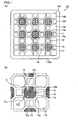
- the outer wall has corner portions, and a side, which contacts the outer wall, of each exhaust gas introduction cell adjacent to the outer wall is straight and parallel to a side defining an outer surface of the outer wall so that the thickness of the outer wall is uniform excluding the corner portions in the cross section perpendicular to the longitudinal direction of the cells.
- the pattern (2) in the above description of three patterns concerning the outer wall and the exhaust gas introduction cell adjacent to the outer wall applies to the honeycomb filter of such an embodiment.
- the above-mentioned structure enables not only enhancement of the strength of the honeycomb fired body by the outer wall but also further reduction of the partial variation in the volume ratio between the exhaust gas emission cells and the exhaust gas introduction cells in the honeycomb fired body. Consequently, the uniform flow of exhaust gas is achieved so that the pressure loss can be reduced.
- the exhaust gas emission cells, the first exhaust gas introduction cells, and the second exhaust gas introduction cells are all square.
- the honeycomb filter of the present invention can achieve the above effects, unlike the honeycomb filter 110 of the prior art described above.
- the cross-sectional area of each second exhaust gas introduction cell is equal to that of each exhaust gas emission cell, and the cross-sectional area of each first exhaust gas introduction cell is 20 to 50% of the cross-sectional area of each second exhaust gas introduction cell.
- the honeycomb filter having the above structure can create a difference between the resistance generated upon flowing of exhaust gas through the first exhaust gas introduction cells and the resistance generated upon flowing of exhaust gas through the second exhaust gas introduction cells, thus effectively suppressing the pressure loss.
- the cross-sectional area of the first exhaust gas introduction cell is less than 20% of the cross-sectional area of the second exhaust gas introduction cell, the flow resistance generated upon flowing of exhaust gas through the first exhaust gas introduction cell will increase and the pressure loss tends to be high because the cross-sectional area of the first exhaust gas introduction cell is too small. If the cross-sectional area of the first exhaust gas introduction cell is more than 50% of the cross-sectional area of the second exhaust gas introduction cell, the pressure loss will be difficult to reduce because the difference in flow resistance between these cells is small.
- the exhaust gas emission cells in the direction perpendicular to the longitudinal direction of the cells, preferably, the exhaust gas emission cells have a square cross section, the first exhaust gas introduction cells have a square cross section, and the second exhaust gas introduction cells have a square cross section, the cross-sectional shape of each second exhaust gas introduction cell is congruent with the cross-sectional shape of each exhaust gas emission cell, the exhaust gas emission cells, the first exhaust gas introduction cells, and the second exhaust gas introduction cells are arranged in the following manner: the exhaust gas emission cells are each surrounded by four first exhaust gas introduction cells and four second exhaust gas introduction cells, which are alternately arranged, across the porous cell walls; provided that hypothetical segments connecting the centroids of the square cross sections of the four second exhaust gas introduction cells surrounding an exhaust gas emission cell are drawn, then an intersection of two hypothetical segments intersecting a shape region corresponding to the cross-sectional shape of the exhaust gas emission cell coincides with the centroid of the square cross section of the exhaust gas emission cell; and four hypothetical segments that do not intersect the shape region corresponding to the
- the outer wall has corner portions, and a side, which contacts the outer wall, of each exhaust gas introduction cell adjacent to the outer wall is straight and parallel to a side defining an outer surface of the outer wall so that the thickness of the outer wall is uniform excluding the corner portions in the cross section perpendicular to the longitudinal direction of the cells.
- the pattern (2) in the above description of three patterns concerning the outer wall and the exhaust gas introduction cell adjacent to the outer wall applies to the honeycomb filter of such an embodiment.
- the above-mentioned structure enables not only enhancement of the strength of the honeycomb fired body by the outer wall but also further reduction of the partial variation in the volume ratio between the exhaust gas emission cells and the exhaust gas introduction cells in the honeycomb fired body. Consequently, the uniform flow of exhaust gas is achieved so that the pressure loss can be reduced.
- the vertex portions of the polygonal cells are formed by curved lines.
- honeycomb filter having cells with vertex portions formed by curved lines according to the above structure are not susceptible to concentration of stress derived from heat or the like in the corner portions of the cells. Thus, cracks are not easily formed.
- the first exhaust gas introduction cells, and the second exhaust gas introduction cells are point-symmetrical polygons each having not more than eight sides.
- the cells each having a point-symmetrical polygonal shape with not more than eight sides can reduce the resistance generated upon flowing of exhaust gas through the cells, and thus can further reduce the pressure loss.
- the exhaust gas introduction cells include two kinds of cells consisting of first exhaust gas introduction cells and second exhaust gas introduction cells having a larger cross-sectional area than the first exhaust gas introduction cells in a direction perpendicular to the longitudinal direction of the cells, the cross-sectional area of each exhaust gas emission cell in a direction perpendicular to the longitudinal direction of the cell is equal to or larger than that of each second exhaust gas introduction cell in a direction perpendicular to the longitudinal, and in the cross section perpendicular to the longitudinal direction of the cells, the exhaust gas introduction cells and the exhaust gas emission cells are formed by curved lines, and the cell wall separating the first exhaust gas introduction cell and the exhaust gas emission cell is thinner than the cell wall separating the second exhaust gas introduction cell and the exhaust gas emission cell.
- the cell wall separating the first exhaust gas introduction cell and the exhaust gas emission cell is thinner than the cell wall separating the second exhaust gas introduction cell and the exhaust gas emission cell, exhaust gas easily passes through the cell walls each separating the first exhaust gas introduction cell and the exhaust gas emission cell at an initial stage. Then, after accumulation of a certain amount of PM, exhaust gas starts passing through the cell walls each separating the second exhaust gas introduction cell and the exhaust gas emission cell.
- the second exhaust gas introduction cells have a larger cross-sectional area than the first exhaust gas introduction cells, and the cross-sectional area of each exhaust gas emission cell is equal to or larger than that of each second exhaust gas introduction cell.
- the exhaust gas introduction cells and the exhaust gas emission cells are formed by curved lines, and the thickness of the cell walls each separating the first exhaust gas introduction cell and the exhaust gas emission cell is 40 to 75% of the thickness of the cell walls each separating the second exhaust gas introduction cell and the exhaust gas emission cell.
- the thickness of the cell walls each separating the first exhaust gas introduction cell and the exhaust gas emission cell is 40 to 75% of the thickness of the cell walls each separating the second exhaust gas introduction cell and the exhaust gas emission cell in the honeycomb filter of the present invention.
- the honeycomb filter will have poor mechanical characteristics because the cell walls each separating the first exhaust gas introduction cell and the exhaust gas emission cell have to be extremely thin. If the thickness of the cell wall separating the first exhaust gas introduction cell and the exhaust gas emission cell is more than 75% of the thickness of the cell wall separating the second exhaust gas introduction cell and the exhaust gas emission cell, the above pressure loss reduction effect may not be obtained because the difference in the thickness between these cell walls is insignificant.
- the exhaust gas emission cells, the first exhaust gas introduction cells, and the second exhaust gas introduction cells are all circular.
- the exhaust gas emission cells and the second exhaust gas introduction cells each preferably have a convex square cross section formed by four outwardly curved lines, whereas the first exhaust gas introduction cells each preferably have a concave square cross section formed by four inwardly curved lines.
- convex square refers to a shape formed by four outwardly curved lines of the same length. The square looks as if its sides bulge from the centroid to the outside.
- concave square refers to a shape formed by four inwardly curved lines of the same length. The square looks as if its sides concave toward the centroid.
- the exhaust gas emission cells, the first exhaust gas introduction cells, and the second exhaust gas introduction cells are configured as described above.
- the exhaust gas emission cells have a larger cross-sectional area than the first exhaust gas introduction cells, resulting in a honeycomb filter in which the relationship among the exhaust gas emission cells, first exhaust gas introduction cells, and second exhaust gas introduction cells in terms of the size is the same as that in the present invention. Consequently, the effects of the present invention can be achieved.
- the cross-sectional area of each second exhaust gas introduction cell is equal to that of each exhaust gas emission cell, and the cross-sectional area of each first exhaust gas introduction cell is 20 to 50% of the cross-sectional area of each second exhaust gas introduction cell.
- the honeycomb filter having the above structure can create a difference between the resistance generated upon flowing of exhaust gas through the first exhaust gas introduction cells and the resistance generated upon flowing of exhaust gas through the second exhaust gas introduction cells, thus effectively suppressing the pressure loss.
- the cross-sectional area of the first exhaust gas introduction cell is less than 20% of the cross-sectional area of the second exhaust gas introduction cell, the flow resistance generated upon flowing of exhaust gas through the first exhaust gas introduction cell will increase and the pressure loss tends to be high because the cross-sectional area of the first exhaust gas introduction cell is too small. If the cross-sectional area of the first exhaust gas introduction cell is more than 50% of the cross-sectional area of the second exhaust gas introduction cell, the pressure loss will be difficult to reduce because the difference in flow resistance between these cells is small.
- the exhaust gas introduction cells preferably include two kinds of cells consisting of the first exhaust gas introduction cells and the second exhaust gas introduction cells having a larger cross-sectional area than the first exhaust gas introduction cells in a direction perpendicular to the longitudinal direction of the cells.
- a smaller number of exhaust gas introduction cells each having a smaller cross-sectional area than each second exhaust gas introduction cell provides a larger effective introduction cell area, thereby allowing PM to be thinly and widely accumulate.
- the above honeycomb filter includes honeycomb fired bodies, and the honeycomb fired body preferably includes silicon carbide or silicon-containing silicon carbide.
- the silicon carbide and silicon-containing silicon carbide are materials excellent in heat resistance. Thus, the honeycomb filter will have better heat resistance.
- the cell walls preferably have a porosity of 40 to 65%.
- the cell walls have a porosity of 40 to 65%, the cell walls can favorably capture PM in exhaust gas. Also, an increase in the pressure loss due to the cell walls can be suppressed. Thus, a honeycomb filter is provided which has low initial pressure loss and in which the pressure loss does not easily increase even after accumulation of PM.
- the cell walls have a porosity of less than 40%, exhaust gas will not easily pass through the cell walls due to the small proportion of the pores in the cell walls, resulting in high pressure loss generated upon passage of exhaust gas through the cell walls. If the cell walls have a porosity of more than 65%, the cell walls will have poor mechanical characteristics, and thus cracks will be easily formed during regeneration or the like.
- the cell walls preferably have pores having an average pore diameter of 8 to 25 ⁇ m.
- the pore diameter is measured by a mercury injection method under conditions of the contact angle of 130° and the surface tension of 485 mN/m.
- the honeycomb filter having the above structure can capture PM at a high capturing efficiency while suppressing an increase in the pressure loss. If the average pore diameter of the pores in the cell walls is less than 8 ⁇ m, the pressure loss generated upon passage of exhaust gas through the cell wall will be high because the pores are too small. In contrast, if the average pore diameter of the pores in the cell walls is more than 25 ⁇ m, PM capturing efficiency will decrease because the pore diameter is too large.
- the honeycomb filter of the present invention preferably has a peripheral coat layer formed on the periphery thereof.
- the peripheral coat layer functions to mechanically protect the cells inside.
- a honeycomb filter having excellent mechanical characteristics such as compression strength is obtained.
- the first exhaust gas introduction cells, the second exhaust gas introduction cells, and the exhaust gas emission cells each have a uniform cross-sectional shape throughout from the end at the exhaust gas inlet side to the end at the exhaust gas outlet side excluding the plugged portion
- the cross-sectional shape is different between the first exhaust gas introduction cell and the second exhaust gas introduction cell
- the cross-sectional shape is also different between the exhaust gas emission cell and the first exhaust gas introduction cell.
- the term “different” means "not congruent” but encompasses "similar”. In other words, if the cross-sectional shapes are similar to each other, the cross-sectional shapes are considered different from each other.
- Each first exhaust gas introduction cell itself has a uniform cross-sectional shape at any cross section thereof
- each second exhaust gas introduction cell itself has a uniform cross-sectional shape at any cross section thereof
- each exhaust gas emission cell has a uniform cross-sectional shape at any cross section thereof.
- each first exhaust gas introduction cell has a different cross-sectional shape from each second exhaust gas introduction cell
- each exhaust gas emission cell also has a different cross-sectional shape from each first exhaust gas introduction cell.
- the honeycomb filter of the present invention preferably has the following structure.
- a cell unit having a cell structure described below is two-dimensionally repeated, where the first exhaust gas introduction cells and the second exhaust gas introduction cells surrounding each exhaust gas emission cell in the unit are shared between the adjacent cell units.
- each exhaust gas emission cell is adjacently surrounded fully by the exhaust gas introduction cells across the porous cell walls, the exhaust gas introduction cells including two kinds of cells consisting of first exhaust gas introduction cells and second exhaust gas introduction cells having a larger cross-sectional area than the first exhaust gas introduction cells in a direction perpendicular to the longitudinal direction of the cells, and the cross-sectional area of each exhaust gas emission cell in a direction perpendicular to the longitudinal direction of the cell is equal to or larger than that of each second exhaust gas introduction cell in a direction perpendicular to the longitudinal direction of the cell, and the exhaust gas introduction cells and the exhaust gas emission cells have the following feature A or B in the cross section perpendicular to the longitudinal direction of the cells:
- Such a honeycomb filter is preferred because the two-dimensional repetition of the cell unit forms a filter having a large capacity.
- the filter has an outer wall, and the cell units naturally do not extend outwardly of the outer wall. The cell units are cut out properly to fit the shape of the outer wall.
- a first embodiment which is one embodiment of the honeycomb filter of the present invention is described below.
- the honeycomb filter according to the first embodiment of the present invention includes a plurality of honeycomb fired bodies combined with one another by adhesive layers residing therebetween.
- Each honeycomb fired body includes exhaust gas emission cells each having an open end at an exhaust gas outlet side and a plugged end at an exhaust gas inlet side, and exhaust gas introduction cells each having an open end at the exhaust gas inlet side and a plugged end at the exhaust gas outlet side, the exhaust gas introduction cells including first exhaust gas introduction cells and second exhaust gas introduction cells.
- Each honeycomb fired body has an outer wall on the periphery thereof.
- the exhaust gas emission cells are each adjacently surrounded fully by the first exhaust gas introduction cells and the second exhaust gas introduction cells across the porous cell walls.
- each second exhaust gas introduction cell has a larger cross-sectional area than each first exhaust gas introduction cell, and the cross-sectional area of each exhaust gas emission cell is equal to that of each second exhaust gas introduction cell.
- the exhaust gas emission cells and the exhaust gas introduction cells are all polygonal, and a side facing the exhaust gas emission cell among the sides forming the cross-sectional shape of each first exhaust gas introduction cell is longer than a side facing the exhaust gas emission cell among the sides forming the cross-sectional shape of each second exhaust gas introduction cell, the cells adjacent to the outer wall consist of the exhaust gas introduction cells.
- the outer wall has corner portions, and a side, which contacts the outer wall, of each exhaust gas introduction cell adjacent to the outer wall is straight and parallel to a side defining an outer surface of the outer wall so that the thickness of the outer wall is uniform excluding the corner portions in the cross section perpendicular to the longitudinal direction of the cells.
- the exhaust gas introduction cells and the exhaust gas emission cells each have a uniform cross-sectional shape throughout from the end at the exhaust gas inlet side to the end at the exhaust gas outlet side excluding the plugged portion.
- Fig. 5 is a perspective view schematically illustrating one example of the honeycomb filter according to the first embodiment of the present invention.
- Fig. 6(a) is a perspective view schematically illustrating one example of the honeycomb fired body forming the honeycomb filter shown in Fig. 5 .
- Fig. 6 (b) is an A-A line cross-sectional view of the honeycomb fired body shown in Fig. 6(a) .
- the honeycomb filter 20 shown in Fig. 5 includes a ceramic block 18 formed by combining a plurality of honeycomb fired bodies 10 via an adhesive layer 15 therebetween, and has a peripheral coat layer 16 on the periphery of the ceramic block 18 for preventing leakage of emission gas.
- the peripheral coat layer 16 may be formed as needed.
- the honeycomb fired body 10 has a rectangular pillar shape, and the corner portions on its end faces are chamfered to be formed by curved lines as shown in Fig. 6(a) . This prevents thermal stress concentration at the corner portions to thereby prevent occurrence of damage such as cracks.
- the corner portions may be angularly chamfered.
- the exhaust gas emission cells each have an open end at the exhaust gas outlet side and a plugged end at the exhaust gas inlet side
- the exhaust gas introduction cells each have an open end at the exhaust gas inlet side and a plugged end at the exhaust gas outlet side.
- the plug 11 is preferably made of the same material used for the honeycomb fired body.
- the exhaust gas emission cells 11 having an octagonal cross section are each adjacently surrounded fully by the first exhaust gas introduction cells 12 each having a square cross section and the second exhaust gas introduction cells 14 each having an octagonal cross section across the porous cell walls.
- the first exhaust gas introduction cells 12 and the second exhaust gas introduction cells 14 are alternately arranged around each exhaust gas emission cell 11.
- Each second exhaust gas introduction cell 14 has a larger cross-sectional area than each first exhaust gas introduction cell 12, and the cross-sectional area of each exhaust gas emission cell 11 is equal to that of each second exhaust gas introduction cell 14.
- An outer wall 17 is formed on the periphery of the honeycomb fired body 10. Cells adjacent to the outer wall 17 consist of the exhaust gas introduction cells (the first exhaust gas introduction cells 12 and the second exhaust gas introduction cells 14).
- the second exhaust gas introduction cells 14 and exhaust gas emission cells 11 have octagonal cross sections, and the cross sections are congruent with each other.
- a side, which contacts the outer wall 17, of the exhaust gas introduction cells adjacent to the outer wall 17 is straight and parallel to a side defining an outer surface of the outer wall 17 so that the thickness of the outer wall 17 is uniform excluding the corner portions in the cross section perpendicular to the longitudinal direction of the cells.
- each second exhaust gas introduction cell 14A adjacent to the outer wall 17 is partially cut so that the cross-sectional shape is changed from octagon to hexagon.
- the cross-sectional shape of each first exhaust gas introduction cell 12A may be in a partially cut shape but is preferably congruent with the cross-sectional shape of each first exhaust gas introduction cell 12.
- the cross section of second exhaust gas introduction cells 14B at each corner of the honeycomb fired body 10 is changed from octagon to generally pentagon including chamfered portions 140 formed by curved lines.
- the chamfered portions 140 of the second exhaust gas introduction cells 14B illustrated in Fig. 6 (a) are chamfered to be curved but may be angularly chamfered.
- the above structure can increase the strength of the honeycomb fired body by the outer wall and can also further reduce the partial variation in the volume ratio of the exhaust gas emission cells and the exhaust gas introduction cells in the honeycomb fired body. Consequently, the flow of exhaust gas becomes more uniform so that the pressure loss can be reduced.
- the first exhaust gas introduction cells 12 and the second exhaust gas introduction cells 14 are alternately arranged along the outer wall 17. Inside those cells, the exhaust gas emission cells 11 are orderly arranged with the first exhaust gas introduction cells 12 and the second exhaust gas introduction cells residing therebetween. As above, the exhaust gas emission cells 11, the first exhaust gas introduction cells 12, and the second exhaust gas introduction cells 14 are arranged in a significantly ordered manner.
- the exhaust gas emission cells 11 and the second exhaust gas introduction cells 14 have the same octagonal shape.
- the octagon is point-symmetry with respect to the centroid.
- all hypotenuse sides (denoted by 14a in Fig. 4 ) have the same length
- all vertical or horizontal sides (denoted by 14b in Fig. 4 ) have the same length.
- four first sides (the hypotenuse sides) and four second sides (the vertical or horizontal sides) are alternately arranged. Each first side and teach second side form an angle of 135°.
- hypotenuse side usually refers to the longest side that is opposite to the right angle in a right-angled triangle.
- the term “hypotenuse side” herein refers to a side, such as the side 14a and the side 11b, that has a certain angle, except for 90° and 0°, relative to four hypothetical segments described below.
- vertical or horizontal side herein refers to sides, such as the side 14b and the side 11a, that are parallel or perpendicular to the four hypothetical segments described below.
- hypothetical segments mentioned in the explanation of the "hypotenuse side” and “vertical or horizontal sides” refer to the four hypothetical segments that do not intersect the cross-sectional figure of the exhaust gas emission cell 11 (these four segments form a square) among the hypothetical segments connecting the centroids of the cross-sectional figures of the four second exhaust gas introduction cells 14 arranged around the exhaust gas emission cell 11.
- Each first exhaust gas introduction cell 12 has a square cross section.
- the side 11a facing the first exhaust gas introduction cell 12 across the cell wall 13 among the sides of the octagonal exhaust gas emission cell 11 is parallel to the side 12a facing the exhaust gas emission cell 11 across the cell wall 13 among the sides of the square first exhaust gas introduction cell 12.
- the side 11b facing the octagonal second exhaust gas introduction cell 14 across the cell wall 13 among the sides of the octagonal exhaust gas emission cells 11 is parallel to the side 14a facing the exhaust gas emission cell 11 across the cell wall 13 among the sides of the octagonal second exhaust gas introduction cell 14.
- the side 12b facing the second exhaust gas introduction cell 14 across the cell wall 13 among the sides of the first exhaust gas introduction cell 12 is parallel to the side 14b facing the first exhaust gas introduction cell 12 across the cell wall 13 among the sides of the second exhaust gas introduction cell 14.
- the distance between the parallel sides is the same in any pair. That is, the distance between the parallel sides 11a and 12a, the distance between the parallel sides 11b and 14a, and the distance between the parallel sides 12b and 14b are the same.
- the exhaust gas emission cells 11, the first exhaust gas introduction cells 12, and the second exhaust gas introduction cells 14 are arranged so as to satisfy the following conditions.
- the octagonal exhaust gas emission cell 11 is adjacently surrounded by four first square exhaust gas introduction cells 12 and four second octagonal exhaust gas introduction cells 14, which are alternately arranged, across the cell walls 13 to form one unit.
- This unit is two-dimensionally repeated, where the first exhaust gas introduction cells 12 and the second exhaust gas introduction cells 14 in the unit are shared between the adjacent cell units, to form a honeycomb filter. Since the units share the first exhaust gas introduction cells 12 and the second exhaust gas introduction cells 14, the first exhaust gas introduction cell 12 and the second exhaust gas introduction cell 14, which adjoin the exhaust gas emission cell 11 across the cell wall 13, also adjoin the exhaust gas emission cell 11 in the adjacent unit across the cell wall 13.
- Fig. 7 is an enlarged cross-sectional view perpendicular to the longitudinal direction of the cells of the honeycomb filter.
- Fig. 7 illustrates how each cell unit (cell structure) is two-dimensionally (i.e. in X and Y directions shown in Fig. 7 ) repeated in the case where the second exhaust gas introduction cells 14 and the exhaust gas emission cells 11 are octagonal, the first exhaust gas introduction cells 12 are square in the cross section of the cells, and the above conditions are satisfied; and also illustrates how the first exhaust gas introduction cells 12 and the second exhaust gas introduction cells 14 are shared between the cell units (cell structures).
- a cell unit 1, a cell unit 2, and a cell unit 3 each have a structure in which the exhaust gas emission cell 11 is fully surrounded by four first exhaust gas introduction cells 12 and four second exhaust gas introduction cells 14, which are alternately arranged, across the cell walls 13 so as to satisfy the above conditions.
- the cell unit 2 has the same structure as the cell unit 1 and is adjacent to the cell unit 1 in the X direction while sharing one first exhaust gas introduction cell 12 and two second exhaust gas introduction cells 14 with the cell unit 1.
- the cells shared between the cell unit 1 and the cell unit 2 are depicted as "shared portion 2" in Fig. 7 .
- the cell unit 3 has the same structure as the cell unit 1 and is adjacent to the cell unit 1 in the Y direction while sharing one first exhaust gas introduction cell 12 and two second exhaust gas introduction cells 12 with the cell unit 1.
- the cells shared between the cell unit 1 and the cell unit 3 are depicted as "shared portion 1" in Fig. 7 .
- Fig. 7 shows hypothetical segments connecting the centroids of the octagonal shapes of four second exhaust gas introduction cells 14, wherein, among these hypothetical segments, four segments H, I, J, and K do not intersect the octagonal region of the exhaust gas emission cell 11, and two segments L and M intersect the octagonal region of the exhaust gas emission cell 11.
- the "shared portion 2" is depicted by hatched lines oriented in the same direction as the segment M
- the "shared portion 1" is depicted by hatched lines oriented in the same direction as the segment L.
- the cross-sectional shapes of the exhaust gas emission cells and the exhaust gas introduction cells forming the honeycomb filter of the present invention are not limited to the above shapes, and may be all square as described below, or may be combinations of other polygons.
- the exhaust gas emission cells 11, the first exhaust gas introduction cells 12, and the second exhaust gas introduction cells 14, which are polygons in the cross section thereof, may be roundly chamfered so that the vertex portions are formed by curved lines in the cross section.
- the curved lines include curved lines obtained by dividing a circle into quarters, and curved lines obtained by dividing an ellipse into quarters along the long axis and a straight line perpendicular to the long axis.
- the vertex portions of the cells each having a rectangular cross section are preferably chamfered (formed by curved lines) in the cross section. This prevents stress concentration at the vertex portions, thereby preventing cracking in the cell wall.
- honeycomb filter 20 may partially include cells formed by curved lines such as a cell having a circular cross section, as needed.
- each first exhaust gas introduction cell 12 is preferably 20 to 50%, more preferably 22 to 45% of the cross-sectional area of each second exhaust gas introduction cell 14.
- each exhaust gas emission cell 11 is equal to that of each second exhaust gas introduction cell 14; however, the cross-sectional area of each exhaust gas emission cell 11 may be larger than that of each second exhaust gas introduction cell 14.
- each exhaust gas emission cell 11 is preferably 1.05 to 1.5 times the cross-sectional area of each second exhaust gas introduction cell 14.
- the side 12a that faces the exhaust gas emission cell 11 among the sides forming the cross-sectional shape of each first exhaust gas introduction cell 12 is longer than the side 14a that faces the exhaust gas emission cell 11 among the sides forming the cross-sectional shape of each second exhaust gas introduction cell 14.
- the sides 12a and 14a are sides facing the exhaust gas emission cell 11.
- the ratio of the length of the side 14a of the second exhaust gas introduction cell 14 to the length of the side 12a of the first exhaust gas introduction cell 12 is not particularly limited, and is preferably not more than 0.8, more preferably not more than 0.7, still more preferably not more than 0.5.
- exhaust gas G1 exhaust gas is represented by an arrow G1 which shows the flow of exhaust gas in Fig. 6(b)
- exhaust gas G1 exhaust gas is represented by an arrow G1 which shows the flow of exhaust gas in Fig. 6(b)
- arrow G1 which shows the flow of exhaust gas in Fig. 6(b)
- PM and the like in the exhaust gas are captured so that the cell walls 13 function as filters.
- the exhaust gas emission cells 11, the first exhaust gas introduction cells 12, and the second exhaust gas introduction cells 14 allow flow of gas such as exhaust gas as described above.
- gas inlet side end an end at a first end face 10a of the honeycomb fired body 10 (the end of the side at which the exhaust gas emission cells 11 are plugged)
- an end at a second end face 10b of the honeycomb fired body 10 is referred to as an exhaust gas outlet side end.
- the honeycomb filter 20 having the above structure can reduce the initial pressure loss, compared to conventional honeycomb filters; reduce the rate of increase in the pressure loss even after accumulation of a considerable amount of PM on the cell walls; and significantly reduce the pressure loss throughout the use from the initial stage to accumulation of PM in an amount close to the limit.
- the thickness of the outer wall 17a is entirely uniform, the strength of the honeycomb fired body is enhanced by the outer wall 17a, and the partial variation in the volume ratio is further reduced between the exhaust gas emission cells and the exhaust gas introduction cells in the honeycomb fired body. Consequently, the flow of exhaust gas becomes more uniform so that the pressure loss can be reduced. Moreover, since the outer wall 17a is chamfered, stress is prevented from concentrating on the corner portions of the honeycomb fired body 10a, so that cracks are not easily formed in the corner portions of the honeycomb fired body 10a.
- each second exhaust gas introduction cell 14B positioned at the corner portion is a pentagon formed by straight lines without having the chamfered portion 140A formed by curved lines
- the second exhaust gas introduction cell 14B positioned close to the corner portion of the honeycomb fired body 10a is likely to have a stress concentrated thereon to easily have cracks.
- each second exhaust gas introduction cell 14B since each second exhaust gas introduction cell 14B has the chamfered portion 140, cracks are not easily formed in the second exhaust gas introduction cell 14B.
- the honeycomb filter 20 includes a plurality of honeycomb fired bodies 10.
- materials of the honeycomb fired bodies 10 include carbide ceramics such as silicon carbide, titanium carbide, tantalum carbide, and tungsten carbide; nitride ceramics such as aluminum nitride, silicon nitride, boron nitride, and titanium nitride; and oxide ceramics such as alumina, zirconia, cordierite, mullite, aluminum titanate, and silicon-containing silicon carbide, and the like. Silicon carbide or silicon-containing silicon carbide is preferred among the examples as they are excellent in heat resistance, mechanical strength, thermal conductivity and the like.
- the silicon-containing silicon carbide is a mixture of silicon carbide and silicon metal, and is preferably silicon-containing silicon carbide including 60 wt% or more of silicon carbide.
- the thickness of the cell walls separating the cells is preferably uniform throughout the cell walls in the honeycomb fired body 10 forming the honeycomb filter 20 according to the first embodiment.
- the cell wall thickness is preferably 0.10 to 0.46 mm, more preferably 0.15 to 0.31 mm.
- the thickness of the outer wall 17 is preferably 0.10 to 0.50 mm.
- the cell wall thickness is a value measured as the thickness D shown in Fig. 1(b) based on the above definition.
- the porosity of the cell wall and the outer wall 17 is preferably 40 to 65% in the honeycomb fired body 10 forming the honeycomb filter 20 according to the first embodiment.
- the average pore diameter of pores in the cell wall is preferably 8 to 25 ⁇ m in the honeycomb fired body 10 forming the honeycomb filter 20 according to the first embodiment.
- the number of the cells per unit area is preferably 31 to 62 pcs/cm 2 (200 to 400 pcs/inch 2 ) in the cross section of the honeycomb fired body 10.
- the honeycomb filter 20 is formed by combining, via an adhesive layer therebetween, a plurality of honeycomb fired bodies each having an outer wall on the periphery thereof.
- An adhesive layer that combines the honeycomb fired bodies is prepared by applying an adhesive paste that contains an inorganic binder and inorganic particles, and drying the adhesive paste.
- the adhesive layer may further contain at least one of inorganic fibers and whiskers.
- the adhesive layer preferably has a thickness of 0.5 to 2.0 mm.
- the honeycomb filter according to the first embodiment of the present invention may have a peripheral coat layer on the periphery thereof.
- the materials of the peripheral coat layer are preferably the same as those of the adhesive layer.
- the peripheral coat layer preferably has a thickness of 0.1 to 3.0 mm.
- silicon carbide is used as ceramic powder.
- a molding step for manufacturing a honeycomb molded body is performed by extrusion-molding a wet mixture containing ceramic powder and a binder.
- ceramic powder silicon carbide powders having different average particle sizes
- an organic binder organic binder
- a liquid plasticizer organic binder
- a lubricant e.g., glycerol
- the wet mixture may contain, as needed, a pore-forming agent such as balloons that are fine hollow spheres including oxide-based ceramics, spherical acrylic particles, or graphite.
- a pore-forming agent such as balloons that are fine hollow spheres including oxide-based ceramics, spherical acrylic particles, or graphite.
- the balloons are not particularly limited, and examples thereof include alumina balloons, glass microballoons, shirasu balloons, fly ash balloon (FA balloons), and mullite balloons.
- Alumina balloons are preferred among these examples.
- the wet mixture is charged into an extrusion molding machine and extrusion-molded to manufacture a honeycomb molded body having a predetermined shape.
- a honeycomb molded body is manufactured with a die that can make cross-sectional shapes having the cell structures (i.e., shapes and arrangement of the cells) shown in Figs. 4 and 6 .
- honeycomb molded bodies are cut at a predetermined length and dried by a dryer such as a microwave dryer, a hot-air dryer, a dielectric dryer, a reduced-pressure dryer, a vacuum dryer, or a freeze dryer. Then, predetermined cells are plugged by placing a plug material paste as a plug material (plugging step).
- a dryer such as a microwave dryer, a hot-air dryer, a dielectric dryer, a reduced-pressure dryer, a vacuum dryer, or a freeze dryer.
- the wet mixture may be used as the plug material paste.
- honeycomb molded body is heated at 300°C to 650°C in a degreasing furnace to remove organic matters in the honeycomb molded body (degreasing step).
- degreased honeycomb molded body is then transferred to a firing furnace and fired at 2000°C to 2200°C (firing step). In this manner, the honeycomb fired body as shown in Figs. 4 to 6 is manufactured.
- the plug material paste placed at the end of the cells is heated to be fired to be a plug material.
- the cutting, drying, plugging, degreasing, and firing may be performed under conditions that have been conventionally employed for manufacturing honeycomb fired bodies.
- a plurality of honeycomb fired bodies are stacked in series via the adhesive paste therebetween on a support table to combine the honeycomb fired bodies (combining step) so that a honeycomb aggregate body including the plurality of stacked honeycomb fired bodies is manufactured.
- the adhesive paste contains, for example, an inorganic binder, an organic binder, and inorganic particles.
- the adhesive paste may further contain inorganic fibers and/or whiskers.
- Examples of the inorganic particles in the adhesive paste include carbide particles, nitride particles, and the like. Specific examples thereof include inorganic particles of silicon carbide, silicon nitride, boron nitride, and the like. There may be used alone or in combination of two or more thereof. Among the inorganic particles, silicon carbide particles are preferred because of their excellent thermal conductivity.
- Examples of the inorganic fibers and/or whiskers in the adhesive paste include inorganic fibers and/or whiskers of silica-alumina, mullite, alumina, and silica. These may be used alone or in combination of two or more thereof. Alumina fibers are preferred among the inorganic fibers.
- the inorganic fibers may be biosoluble fibers.
- the adhesive paste may contain, as needed, balloons that are fine hollow spheres including oxide-based ceramics, spherical acrylic particles, graphite, or the like.
- the balloons are not particularly limited, and examples thereof include alumina balloons, glass microballoons, shirasu balloons, fly ash balloons (FA balloon), mullite balloons, and the like.
- the honeycomb aggregate body is heated so that the adhesive paste is solidified to form an adhesive layer, whereby a rectangular pillar-shaped ceramic block is manufactured.
- the heating and solidifying of the adhesive paste may be performed under conditions that have been conventionally employed for manufacturing honeycomb filters.
- the periphery of the ceramic block is cut with a diamond cutter, whereby a ceramic block whose periphery is cut into a substantially round pillar shape is manufactured.
- a peripheral coating material paste is applied to the peripheral face of the substantially round pillar-shaped ceramic block, and is dried and solidified to form a peripheral coat layer (peripheral coat layer forming step).
- the adhesive paste may be used as the peripheral coating material paste.
- the peripheral coating material paste may be a paste having a composition different from that of the adhesive paste.
- the peripheral coat layer is not necessarily formed; it may be formed as needed.
- the peripheral shape of the ceramic block is adjusted by providing the peripheral coat layer, and thereby a round pillar-shaped honeycomb filter is obtained.
- honeycomb filter including the honeycomb fired bodies can be manufactured through the above steps.
- the honeycomb filter having a predetermined shape is manufactured by cutting
- the honeycomb filter may also be formed to have a predetermined shape such as round pillar shape in the following manner: honeycomb fired bodies of various shapes, each having an outer wall on the periphery thereof, are manufactured in the honeycomb fired body manufacturing step, and then the honeycomb fired bodies of various shapes are combined with one another via the adhesive layer therebetween.
- the cutting step can be omitted.
- the honeycomb filter according to the embodiment has a structure in which the entire cell walls around the exhaust gas emission cells can be utilized, and the exhaust gas emission cells are orderly arranged, enabling uniform and smooth flow of exhaust gas.
- This structure not only reduces the initial pressure loss as compared with conventional honeycomb filters but also reduces the rate of increase in the pressure loss even after accumulation of a considerable amount of PM on the cell walls.
- the honeycomb filter can greatly reduce the pressure loss throughout the use from the initial stage to after accumulation of PM in an amount close to the limit.
- the cross-sectional area of each first exhaust gas introduction cell may be 20 to 50% of the cross-sectional area of each second exhaust gas introduction cell.
- the above cross-sectional area ratio of the first exhaust gas introduction cell and the second exhaust gas introduction cell can create a difference between the resistance generated upon flowing of exhaust gas through the first exhaust gas introduction cells and the resistance generated upon flowing of exhaust gas through the second exhaust gas introduction cells, thus effectively suppressing the pressure loss.
- the ratio of the length of the side of the second exhaust gas introduction cell to the length of the side of the first exhaust gas introduction cell may be not more than 0.8.
- the above ratio of the length of the side of the first exhaust gas introduction cell to the length of the side of the second exhaust gas introduction cell allows easier passage of exhaust gas through the cell walls each separating the exhaust gas emission cell and the first exhaust gas introduction cell, thus effectively suppressing the initial pressure loss and suppressing an increase in the rate of increase of the pressure loss even after accumulation of PM.
- the materials of the honeycomb fired bodies may include silicon carbide or silicon-containing silicon carbide. These materials can provide a honeycomb filter having excellent heat resistance.
- the thickness of the cell walls separating the cells may be uniform throughout the cell walls.
- the cell wall thickness may be 0.10 to 0.46 mm.
- the cell wall having the above thickness is sufficient for capturing PM in exhaust gas, and an increase in the pressure loss can be effectively suppressed.
- the porosity of the cell wall and the outer wall forming the honeycomb filter 20 may be 40 to 65%.
- the cell wall having the above porosity can favorably capture PM in exhaust gas. Also, an increase in the pressure loss due to the cell wall can be suppressed.
- the average pore diameter of pores in the cell wall may be 8 to 25 ⁇ m in the honeycomb fired body forming the honeycomb filter.
- the above average pore diameter of pores in the cell wall allows PM to be captured at a high capturing efficiency while suppressing an increase in the pressure loss.
- the exhaust gas introduction cells and the exhaust gas emission cells each have a uniform cross-sectional shape throughout from the end at the exhaust gas inlet side to the end at the exhaust gas outlet side excluding the plugged portion.
- the plugged portions provided at the end at the exhaust gas outlet side i.e., the plugged portions in the first exhaust gas introduction cells and the second exhaust gas introduction cells
- the width of each plugged portion is equal to or greater than the length of one side of the first exhaust gas introduction cell.
- the honeycomb filter of the present invention the plugged portions aligned vertically and horizontally at the exhaust gas outlet side function as thermally conductive layers and also as layers for dissipating heat to the outside.
- the temperature difference can be reduced in the radial direction at the end of the exhaust gas outlet side of the honeycomb filter. This reduces the thermal stress that is generated, thus suppressing cracks.
- the amount of the plug in the second exhaust gas introduction cells where a large amount of PM accumulates compared to the first exhaust gas introduction cells is large in accordance with the size of the cross-sectional area, and thus the thermal capacity of the plugged portions is also large.
- Such plugged portions can suppress an increase in the temperature of the second exhaust gas introduction cells where the heat of burning PM is greater, even in view of each cell unit. This reduces the temperature difference in the radial direction of the honeycomb filter, thereby presumably reducing the thermal stress that occurs.
- the honeycomb filter of the present embodiment can suppress cracks during the regeneration even if some of the exhaust gas introduction cells have square cross sections.
- the above-mentioned structure can increase the strength of the honeycomb fired body by the outer wall and can also further reduce the partial variation in the volume ratio of the exhaust gas emission cells and the exhaust gas introduction cells in the honeycomb fired body. Consequently, the flow of exhaust gas becomes more uniform so that the pressure loss can be reduced.
- a mixture was obtained by mixing 52. 8% by weight of silicon carbide coarse powder having an average particle size of 22 ⁇ m and 22.6% by weight of silicon carbide fine powder having an average particle size of 0.5 ⁇ m.
- an organic binder methylcellulose
- a lubricant UNILUB, manufactured by NOF Corporation
- 1.3% by weight of glycerin 1.9% by weight of a pore-forming agent (acrylic resin)
- acrylic resin 2. 8% by weight of oleic acid
- 13.2% by weight of water followed by kneading to prepare a wet mixture.
- the wet mixture was extrusion-molded (molding step).
- the raw honeycomb molded body was dried by a microwave dryer to manufacture a dried honeycomb molded body. Then, predetermined cells of the dried honeycomb molded body were plugged by filling the cells with a plug material paste.
- the cells were plugged in such a manner that the end at the exhaust gas inlet side and the end at the exhaust gas outlet side were plugged at the positions shown in Fig. 6 (b) .
- the wet mixture was used as the plug material paste. After plugging the cells, the dried honeycomb molded body including the plug material paste was dried again by a dryer.
- the dried honeycomb molded body with the plugged cells was degreased at 400°C (degrease treatment) and then fired at 2200°C (firing treatment) under argon atmosphere at normal pressure for 3 hours.
- the length of the sides and the cross-sectional area described below can be measured by the above image analysis of an electron microscope photograph and by use of the above grain size distribution measurement software (Mac-View (Version 3.5), produced by Mountech Co. Ltd.).
- the manufactured honeycomb fired bodies each were the honeycomb fired body 10 shown in Fig. 6 (a) and Fig. 6 (b) formed of a silicon carbide sintered body and having a porosity of 45%, an average pore diameter of 15 ⁇ m, a size of 34.3 mm x 34.3 mm x 150 mm, the number of cells (cell density) of 290 pcs/inch 2 , and a thickness of cell walls of 0.25 mm.
- each exhaust gas emission cell 11 was adjacently surrounded fully by the first exhaust gas introduction cells 12 and 12A and the second exhaust gas introduction cells 14, 14A, and 14B.
- the first exhaust gas introduction cells 12 and 12A each had a square cross section, and the length of the sides forming the cross section of the first exhaust gas introduction cells 12 and 12A was 0.96 mm.
- each second exhaust gas introduction cell 14 except for the second exhaust gas introduction cells 14A and 14B adjacent to the outer wall 17 the cross section was octagonal, the length of the hypotenuse sides facing the exhaust gas emission cell 11 was 0.27 mm, and the vertical or horizontal sides not facing the exhaust gas emission cell 11 were 1.11 mm.
- each second exhaust gas introduction cell 14 was 0.28 times as long as the length of the sides facing the exhaust gas emission cell 11 among the sides forming the first exhaust gas introduction cell 12.
- each second exhaust gas introduction cell 14B at the four corners the length of the side adjacent to the outer wall 17 was 1.23 mm, the length of the vertical or horizontal sides was 1.04 mm, the length of the hypotenuse side was 0.27 mm, and the cross-sectional area was 1.48 mm 2 .
- each second exhaust gas introduction cell 14A the length of the side adjacent to the outer wall 17 was 1.49 mm, the length of the vertical side parallel to the side adjacent to the outer wall 17 was 1.11 mm, the length of the horizontal side connected at a right angle to the side adjacent to the outer wall 17 was 1.04 mm, the length of the hypotenuse side was 0.27 mm, and the cross-sectional area was 1.79 mm 2 .
- the exhaust gas emission cells 11 had an octagonal cross section, and the shape was the same as the cross section of the second exhaust gas introduction cell 14.
- the length of the hypotenuse side facing the second exhaust gas introduction cell 14 was 0.27 mm, and the vertical or horizontal sides facing the first exhaust gas introduction cells 12 was 1.11 mm.
- the thickness of the outer wall 17 was 0.35 mm.
- each first exhaust gas introduction cell 12 was 0.93 mm 2
- both the cross-sectional area of the second exhaust gas introduction cell 14 and the cross-sectional area of exhaust gas emission cell 11 were 2.17 mm 2
- the cross-sectional area of the first exhaust gas introduction cell 12 was 43% of the cross-sectional area of the second exhaust gas introduction cell 14.
- each exhaust gas emission cell 11 was equal to that of each second exhaust gas introduction cell 14, and was larger than that of the first exhaust gas introduction cell 12.
- the honeycomb fired body had a rectangular pillar shape in which the corner portions of its end faces were chamfered to be formed by curved lines.
- honeycomb fired bodies were combined using an adhesive paste containing 30% by weight of alumina fibers having an average fiber length of 20 ⁇ m, 21% by weight of silicon carbide particles having an average particle size of 0.6 ⁇ m, 15% by weight of silica sol, 5.6% by weight of carboxymethyl cellulose, and28.4% by weight of water. Further, the adhesive layer was dried and solidified at 120°C to form an adhesive layer, whereby a rectangular pillar-shaped ceramic block was manufactured.
- the periphery of the rectangular pillar-shaped ceramic block was cut out using a diamond cutter to manufacture a substantially round pillar-shaped ceramic block.
- a sealing material paste having the same composition as the adhesive paste was applied to the peripheral face of the ceramic block.
- the sealing material paste was then dried and solidified at 120°C to form a peripheral coat layer. In this manner a round pillar-shaped honeycomb filter was manufactured.
- the diameter of the honeycomb filter was 143.8 mm, and the length in the longitudinal direction was 150 mm.
- a raw honeycomb molded body was obtained in the same molding step as in Example 1. Subsequently the raw honeycomb molded body was dried by a microwave dryer to manufacture a dried honeycomb molded body. Then, predetermined cells of the dried honeycomb molded body were plugged by filling the cells with a plug material paste.
- Example 1 The position of plugging of the cells was changed from that in Example 1 as follows. All the octagonal cells were plugged at the end face corresponding to the end at the exhaust gas outlet side, and all the square cells were plugged at the end face corresponding to the end at the exhaust gas inlet side, so that the cells were alternately plugged at both end faces.
- Example 2 the same step as in Example 1 was performed to manufacture a honeycomb fired body 130 shown in Figs. 19 (a) and 19(b) , and then a honeycomb filter 120 was manufactured.
- all the exhaust gas introduction cells 132 had an octagonal cross section, except for the exhaust gas introduction cells 132A and 132B adjacent to the outer wall 137.
- the sides facing the exhaust gas emission cell 131 were vertical or horizontal sides having a length of 1.11 mm.
- the sides facing other exhaust gas introduction cells 132, 132A, and 132B were hypotenuse sides having a length of 0.27 mm.
- All the exhaust gas emission cells 131 and 131A had a square cross section.
- the length of the sides forming the cross sections of the exhaust gas emission cells 131 and 131A was 0. 96 mm.
- each exhaust gas introduction cell 132B at the four corners the length of the side adjacent to the outer wall 137 was 1.23 mm, the length of the vertical or horizontal sides was 1.04 mm, the length of the hypotenuse side was 0.27 mm, and the cross-sectional area was 1.48 mm 2 .
- the length of the side adjacent to the outer wall 137 was 1.49 mm
- the length of the vertical side parallel to the side adjacent to the outer wall 17 was 1.11 mm
- the length of the horizontal line connected at a right angle to the side adjacent to the outer wall 17 was 1.04 mm
- the length of the hypotenuse sides was 0.27 mm
- the cross-sectional area was 1.79 mm 2 .
- the thickness of a cell wall 133 was 0.25 mm, and the thickness of the outer wall was 0.35 mm.
- the cross-sectional area of the exhaust gas introduction cell 132 was 2.17 mm 2 , and the cross-sectional area of the exhaust gas emission cell 131 was 0.93 mm 2 . In other words, the cross-sectional area of each exhaust gas introduction cell 132 was larger than that of each exhaust gas emission cell 131.
- Fig. 8 is a cross-sectional view schematically illustrating a method for measuring the pressure loss.
- a pressure loss measuring apparatus 210 has the following structure: a honeycomb filter 20 fixed inside a metal casing 213 is disposed in an exhaust gas tube 212 of a 1. 6-liter diesel engine 211, and a pressure gauge 214 is attached in a manner that it can detect the pressure in front and back of the honeycomb filter 20.
- the honeycomb filter 20 is disposed such that the end at the exhaust gas inlet side is closer to the exhaust gas tube 212 of the diesel engine 211. Specifically, the honeycomb filter 20 is disposed to allow exhaust gas to flow into the cells whose the exhaust gas inlet side ends are open.
- the diesel engine 211 was operated at a rotation speed of 3100 rpm and a torque of 50 Nm to allow exhaust gas from the diesel engine 211 to flow into the honeycomb filter 20 so that PM was captured by the honeycomb filter.
- Fig. 9 is a graph showing the relationship between the amount of captured PM and the pressure loss as measured in Example 1 and Comparative Example 1.
- the honeycomb filter of Example 1 exhibited a significant effect of achieving low pressure loss, compared to the honeycomb filter of Comparative Example 1, throughout the range from 0 g/L to 8 g/L of the amount of captured PM.
- the initial pressure loss i.e. the pressure loss at 0 g/L of the amount of captured PM
- the pressure loss was 7.2 kPa when the amount of captured PM was 8 g/L.
- honeycomb filter according to the second embodiment of the present invention.
- the honeycomb filter according to the second embodiment of the present invention includes a plurality of honeycomb fired bodies combined with one another by adhesive layers residing therebetween.
- the honeycomb fired bodies each include exhaust gas emission cells each having an open end at an exhaust gas outlet side and a plugged end at an exhaust gas inlet side, and exhaust gas introduction cells each having an open end at the exhaust gas inlet side and a plugged end at the exhaust gas outlet side.
- the exhaust gas introduction cells include first exhaust gas introduction cells and second exhaust gas introduction cells.
- the honeycomb fired bodies each have an outer wall on the outer periphery thereof.
- the exhaust gas emission cells are each adjacently surrounded fully by the first exhaust gas introduction cells and the second exhaust gas introduction cells across the porous cell walls.
- each second exhaust gas introduction cell has a larger cross-sectional area than each first exhaust gas introduction cell, and the cross-sectional area of each exhaust gas emission cell is equal to that of each second exhaust gas introduction cell.
- the exhaust gas emission cells and the exhaust gas introduction cells are all polygonal, a side facing the exhaust gas emission cell among the sides forming the cross-sectional shape of each first exhaust gas introduction cell is longer than a side facing the exhaust gas emission cell among the sides forming the cross-sectional shape of each second exhaust gas introduction cell.
- the cells adjacent to the outer wall consist of the exhaust gas introduction cells.
- the exhaust gas introduction cells and the exhaust gas emission cells each have a uniform cross-sectional shape throughout from the end at the exhaust gas inlet side to the end at the exhaust gas outlet side excluding the plugged portion.
- the honeycomb filter according to the second embodiment has the same structure as that of the honeycomb filter according to the first embodiment. They are the same in terms of the basic shape and arrangement of the cells but different in that, in the honeycomb filter according to the second embodiment, the cross-sectional shape of the cells adjacent to the outer wall is the same as the cross-sectional shape of the cells other than the cells adjacent to the outer wall.
- Fig. 10(a) is a perspective view schematically illustrating one example of a honeycomb filter according to a second embodiment of the present invention.
- Fig. 10(b) is a perspective view illustrating a honeycomb fired body forming the honeycomb filter.
- the cross-sectional shape and arrangement of the cell walls in a honeycomb fired body included in a honeycomb filter 30 shown in Fig. 10(a) and Fig. 10(b) are basically the same as those of the cell walls in the honeycomb fired body 10 included in the honeycomb filer 20 shown in Fig. 6(a) .
- Each exhaust gas emission cell 11 having an octagonal cross section is adjacently surrounded fully by the first exhaust gas introduction cells 12 each having a square cross section and the second exhaust gas introduction cells 14 each having an octagonal cross section across porous cell walls therebetween.
- the first exhaust gas introduction cells 12 and the second exhaust gas introduction cells 14 are alternately arranged around each exhaust gas emission cell 11.
- Each second exhaust gas introduction cell 14 has a larger cross-sectional area than each first exhaust gas introduction cell 12, and the cross-sectional area of each exhaust gas emission cell 11 is equal to that of each second exhaust gas introduction cell 14.
- An outer wall 17a is formed on the periphery of the honeycomb fired bodies 10a. The cells adjacent to the outer wall 17a are all exhaust gas introduction cells (the first exhaust gas introduction cells 12 and the second exhaust gas introduction cells 14).
- the length of a side 12a that faces the exhaust gas emission cell 11 among the sides forming the cross-sectional shape of each first exhaust gas introduction cell 12 is longer than a side 14a that faces the exhaust gas emission cell 11 among the sides forming the cross-sectional shape of each second exhaust gas introduction cell 14.
- the honeycomb fired body 10a is different from the honeycomb fired body 10 included in the honeycomb filter 20 shown in Fig. 6 (a) in that, as shown in Fig. 10(b) , the exhaust gas emission cells, the first exhaust gas introduction cells, and the second exhaust gas introduction cells adjacent to the outer wall respectively have the same cross-sectional shapes as the exhaust gas emission cells 11, the first exhaust gas introduction cells 12, and the second exhaust gas introduction cells 14 other than the cells adjacent to the outer wall.
- Fig. 11(c) is a perspective view schematically illustrating one modified example of a honeycomb filter according to the second embodiment of the present invention.
- Fig. 11 (d) is an end face view of the honeycomb filter in Fig. 11(c) .
- all the first exhaust gas introduction cells 12 have the same shape and all the second exhaust gas introduction cells 14 have the same shape.
- a side 170b corresponding to an outer surface of an outer wall 17b changes in accordance with the shapes of the first exhaust gas introduction cells 12 adjacent to the outer wall 17b and the second exhaust gas introduction cells 14 adjacent to the outer wall 17b.
- the thickness of the outer wall 17b is uniform.
- the side 170b corresponding to the outer surface of the outer wall 17b becomes rugged along with the shapes of the first exhaust gas introduction cells 12 and the second exhaust gas introduction cells 14 adjacent to the outer wall 17b.
- honeycomb filter according to the present embodiment can be manufactured by the same method as described in the first embodiment of the present invention, except that the shape of the mold used in the extrusion molding is changed.
- the honeycomb filter 30 according to the present embodiment is substantially the same as the honeycomb filter 20 according to the first embodiment in terms of the basic arrangement of the cells, shapes, mode of plugging, and the like, and thus can similarly achieve the effects (1) to (10) described in relation to the first embodiment.
- honeycomb filter according to the third embodiment of the present invention is described below.
- the features not described below are substantially the same as those of the honeycomb filter according to the first embodiment.
- the honeycomb filter according to the third embodiment of the present invention includes a plurality of honeycomb fired bodies each having an outer wall on the periphery thereof.
- Each honeycomb fired body includes exhaust gas emission cells each having an open end at an exhaust gas outlet side and a plugged end at an exhaust gas inlet side, and exhaust gas introduction cells each having an open end at the exhaust gas inlet side and a plugged end at the exhaust gas outlet side, the exhaust gas introduction cells including first exhaust gas introduction cells and second exhaust gas introduction cells.
- the honeycomb fired bodies are combined with one another via adhesive layers therebetween.
- the exhaust gas emission cells are each adjacently surrounded fully by the first exhaust gas introduction cells and the second exhaust gas introduction cells across the porous cell wall.
- each second exhaust gas introduction cell has a larger cross-sectional area than each first exhaust gas introduction cell, and the cross-sectional area of each exhaust gas emission cell is equal to that of each second exhaust gas introduction cell.
- the exhaust gas emission cells and the exhaust gas introduction cells are square, and one of the sides forming the cross-sectional shape of each first exhaust gas introduction cell faces the exhaust gas emission cell, and none of the sides forming the cross-sectional shape of each second exhaust gas introduction cell faces the sides forming the exhaust gas emission cell.
- the cells adjacent to the outer wall consist of the exhaust gas introduction cells.
- the exhaust gas introduction cells and the exhaust gas emission cells each have a uniform cross-sectional shape throughout from the end at the exhaust gas inlet side to the end at the exhaust gas outlet side excluding the plugged portion.
- the honeycomb filter according to the third embodiment has substantially the same structure as the honeycomb filter according to the first embodiment, except that the exhaust gas emission cells, the first exhaust gas introduction cells, and the second exhaust gas introduction cells each have a square cross section, and also except for the features described below.
- Fig. 12 (a) is an end face view schematically illustrating one example of the cell arrangement at an end face of the honeycomb fired body forming the honeycomb filter according to the third embodiment of the present invention.
- exhaust gas emission cells 41 each having a square cross section are each adjacently surrounded fully by first exhaust gas introduction cells 42 each having a square cross section and second exhaust gas introduction cells 44 each having a square cross section across porous the cell walls.
- the first exhaust gas introduction cells 42 and the second exhaust gas introduction cells 44 are alternately arranged around each exhaust gas emission cell 41.
- Each second exhaust gas introduction cell 44 has a larger cross-sectional area than each first exhaust gas introduction cell 42, and the cross-sectional area of each exhaust gas emission cell 41 is equal to that of each second exhaust gas introduction cell 44.
- a side 41a that faces the first exhaust gas introduction cell 42 across a cell wall 43 among the sides of the square exhaust gas emission cell 41 is parallel to a side 42a that faces the exhaust gas emission cell 41 across the cell wall 43 among the sides of the square first exhaust gas introduction cell 42.
- a side 42b that faces the second exhaust gas introduction cell 44 across the cell wall 43 among the sides of the first exhaust gas introduction cell 42 is parallel to a side 44b that faces the first exhaust gas introduction cell 42 across the cell wall 43 among the sides of the second exhaust gas introduction cell 44.
- the distance between the parallel sides is the same in any pair. That is, the distance between the parallel sides 41a and 42a and the distance between the parallel sides 42b and 44b are the same.
- the square exhaust gas emission cell 41 is adjacently surrounded by four first square exhaust gas introduction cells 42 and four second square exhaust gas introduction cells 44, which are alternately arranged, across the cell walls 43.
- the cross-sectional area of each second exhaust gas introduction cell 44 is larger than that of each first exhaust gas introduction cell 42.
- exhaust gas emission cells 41, the first exhaust gas introduction cells 42, and the second exhaust gas introduction cells 44 are arranged so as to satisfy the following conditions.
- the square exhaust gas emission cell 41 is adjacently surrounded by four first square exhaust gas introduction cells 42 and four second square exhaust gas introduction cells 44, which are alternately arranged, across the cell walls 43 to form one unit.
- This unit is two-dimensionally repeated, where the first exhaust gas introduction cells 42 and the second exhaust gas introduction cells 44 in the unit are shared between the adjacent cell units, to form a honeycomb filter.
- the units share the first exhaust gas introduction cells 42 and the second exhaust gas introduction cells 44.
- the first exhaust gas introduction cell 42 and the second exhaust gas introduction cell 44 which adjoin the exhaust gas emission cell 41 across the cell wall 43, also adjoin the exhaust gas emission cell 41 in the adjacent unit across the cell wall 43.
- Fig. 13 is an enlarged cross-sectional view perpendicular to the longitudinal direction of the honeycomb filter.
- Fig. 13 illustrates how each cell unit (cell structure) is two-dimensionally (i.e. in X and Y directions shown in Fig. 13 ) repeated in the case where the first exhaust gas introduction cells 42, the second exhaust gas introduction cells 44, and the exhaust gas emission cells 41 are square and the above conditions are satisfied in the cross-sectional shapes of the cells; and also illustrates how the first exhaust gas introduction cells 42 and the second exhaust gas introduction cells 44 in the unit are shared between the cell units (cell structures).
- a cell unit 1, a cell unit 2, and a cell unit 3 each have a structure in which the exhaust gas emission cell 41 is fully surrounded by four first exhaust gas introduction cells 42 and four second exhaust gas introduction cells 44, which are alternately arranged, across the cell walls 43 so as to satisfy the above conditions.
- the cell unit 2 has the same structure as the cell unit 1.
- the cell unit 2 is adjacent to the cell unit 1 in the X direction while sharing one first exhaust gas introduction cell 42 and two second exhaust gas introduction cells 44 with the cell unit 1.
- the cells shared between the cell unit 1 and the cell unit 2 are depicted as "shared portion 2" in Fig. 13 .
- the cell unit 3 has the same structure as the cell unit 1.
- the cell unit 3 is adjacent to the cell unit 1 in the Y direction while sharing one first exhaust gas introduction cell 42 and two second exhaust gas introduction cells 44 with the cell unit 1.
- the cells shared between the cell unit 1 and the cell unit 3 are depicted as "shared portion 1" in Fig. 13 .
- Fig. 13 shows hypothetical segments connecting the centroids of the square shapes of the four second exhaust gas introduction cells 44, wherein, among these hypothetical segments, four segments h, i, j, and k do not intersect the square region of the exhaust gas emission cell 41, and two hypothetical segments l and m intersect the square region of the exhaust gas emission cell 41.
- the "shared portion 2" is depicted by hatched lines oriented in the same direction as the segment m
- the “shared portion 1" is depicted by hatched lines oriented in the same direction as the segment l.
- one of sides forming the cross-sectional shape of the first exhaust gas introduction cell 42 faces the exhaust gas emission cell 41.
- the second exhaust gas introduction cell 44 and the exhaust gas emission cell 41 are arranged so as to face each other at their corner portions.
- none of the sides forming the cross-sectional shape of the second exhaust gas introduction cell 44 faces the exhaust gas emission cell 41.
- the cells adjacent to an outer wall 47 consist of the exhaust gas introduction cells (the first exhaust gas introduction cells 42 and the second exhaust gas introduction cells 44).
- cracks are not easily generated by thermal shock that occurs during burn-removal (regeneration) of PM accumulated on the honeycomb filter.
- the plugged portions provided at the end at the exhaust gas outlet side i.e., the plugged portions in the first exhaust gas introduction cells and the second exhaust gas introduction cells
- the width of each plugged portion is equal to or greater than the length of one side of the first exhaust gas introduction cell.
- the honeycomb filter of the present invention the plugged portions aligned vertically and horizontally at the exhaust gas outlet side function as thermally conductive layers and also as layers for dissipating heat to the outside.
- the temperature difference can be reduced in the radial direction at the end of the exhaust gas outlet side of the honeycomb filter. This reduces the thermal stress that is generated, thus suppressing cracks.
- the amount of the plug in the second exhaust gas introduction cells where a large amount of PM accumulates compared to the first exhaust gas introduction cells is large in accordance with the size of the cross-sectional area, and thus the thermal capacity of the plugged portions is also large.
- Such plugged portions can suppress an increase in the temperature of the second exhaust gas introduction cells where the heat of burning PM is greater, even in view of each cell unit. This presumably reduces the temperature difference in the radial direction of the honeycomb filter, thus reducing the thermal stress that occurs.
- the honeycomb filter of the present embodiment can suppress cracks during the regeneration even though some of the exhaust gas introduction cells have square cross sections.
- each first exhaust gas introduction cell 42 is preferably 20 to 50%, more preferably 22 to 45% of the cross-sectional area of each second exhaust gas introduction cell 44.
- each exhaust gas emission cell 41 is equal to that of each second exhaust gas introduction cell 44; however, the cross-sectional area of each exhaust gas emission cell 41 may be larger than that of each second exhaust gas introduction cell 44.
- each exhaust gas emission cell 41 is preferably 1.05 to 1.5 times the cross-sectional area of each second exhaust gas introduction cell 44.
- the following describes the cell wall thickness in the cross section of the honeycomb filter 40 according to the third embodiment based on the above definition of the cell wall.
- a straight line Z 42 connecting a centroid O 41 of the exhaust gas emission cell 41 and a centroid O 42 of the first exhaust gas introduction cell 42 is drawn, then the thickness of a cell wall portion where the cell wall 43 and the straight line Z 42 overlap each other (the thickness between the side 42a and the side 41a) is defined as a thickness X 1 .
- the thickness of the cell wall 43 separating the second exhaust gas introduction cell 44 and the exhaust gas emission cell 41 corresponds to the thickness of a cell wall portion where the cell wall 43 and the straight line Z 44 overlap each other (the distance between a corner portion 44c of the second exhaust gas introduction cell 44 and a corner portion 41c of the exhaust gas emission cell 41), which is defined as a cell wall thickness Y 1 .
- the cell wall thickness of the honeycomb filter 40 varies depending on the parts as shown in Fig. 12(a) ; however, the thicknesses, including the thickness X 1 and the thickness Y 1 , may be in the range of 0.10 to 0.46 mm.
- Fig. 12 (b) is an end face view illustrating one modified example of the honeycomb filter according to the third embodiment of the present invention.
- a second exhaust gas introduction cell 44A adjacent to an outer wall 47a is, compared to the shape of the second exhaust gas introduction cell 44 not adjacent to the outer wall 47a, partially deformed to be rectangle in accordance with the straight line along the inner walls, which forms the outer wall 47a, in the first exhaust gas introduction cells 44A adjacent to the outer wall 47a.
- a second exhaust gas introduction cell 44B at the corner portion has a square cross-sectional shape with a smaller area compared to the second exhaust gas introduction cell 44 not adjacent to the outer wall 47a.
- the boundary between the outer wall 47a and the first exhaust gas introduction cells 42 or the second exhaust gas introduction cells 44 adjacent to the outer wall 47a is formed linearly, and the thickness of the outer wall 47a is uniform.
- Fig. 12(c) is an end face view illustrating another modified example of the honeycomb filter according to the third embodiment of the present invention.
- all the first exhaust gas introduction cells 42 have the same shape, and all the second exhaust gas introduction cells 44 have the same shape.
- a side 470b defining an outer surface of an outer wall 47b changes in accordance with the shapes of the first exhaust gas introduction cells 42 adjacent to the outer wall 47b and the second exhaust gas introduction cells 44 adjacent to the outer wall 47b.
- the thickness of the outer wall 47b is uniform.
- the side 470b defining the outer surface of the outer wall 47b becomes rugged along with the shapes of the first exhaust gas introduction cells 42 and the second exhaust gas introduction cells 44 adjacent to the outer wall 47b.
- honeycomb filter of the present embodiment can be manufactured in the same manner as in the first embodiment of the present invention, except that a die having a different shape is used in the extrusion molding step.
- the exhaust gas emission cells 41 and the second exhaust gas introduction cells 44 each have a square cross section, and none of the sides forming the cross-sectional shape of the second exhaust gas introduction cells 44 faces the exhaust gas emission cells 41.
- a side 42a faces the exhaust gas emission cell 41.
- the honeycomb filter 40 according to the present embodiment is substantially the same as the honeycomb filter 20 according to the first embodiment in terms of the basic arrangement of the cells, mode of plugging, size difference among the cross-sectional areas of the cells, and the like.
- the honeycomb filter 40 according to the present embodiment can similarly achieve the effects (1) to (4) and (7) to (11) described in relation to the first embodiment.
- a honeycomb filter according to the fourth embodiment of the present invention is described below.
- the features not described below are substantially the same as those of the honeycomb filter according to the first embodiment.
- the honeycomb filter according to the fourth embodiment of the present invention includes a plurality of honeycomb fired bodies each having an outer wall on the periphery thereof.
- Each honeycomb fired body includes exhaust gas emission cells each having an open end at an exhaust gas outlet side and a plugged end at an exhaust gas inlet side, and exhaust gas introduction cells each having an open end at the exhaust gas inlet side and a plugged end at the exhaust gas outlet side, the exhaust gas introduction cells including first exhaust gas introduction cells and second exhaust gas introduction cells each having a larger cross-sectional area than each first exhaust gas introduction cell in a direction perpendicular to the longitudinal direction of the cells.
- the honeycomb fired bodies are combined with one another via adhesive layers therebetween.
- the cross-sectional area of each exhaust gas emission cell in the cross section perpendicular to the longitudinal direction of the cell is equal to that of each second exhaust gas introduction cell in the cross section perpendicular to the longitudinal direction of the cell; the exhaust gas emission cells and the exhaust gas introduction cells are formed by curved lines in the cross section perpendicular to the longitudinal direction of the cells; and the exhaust gas emission cells, the first exhaust gas introduction cells, and the second exhaust gas introduction cells each have a circular cross-sectional shape.
- the cells adjacent to the outer wall consist of exhaust gas introduction cells (first exhaust gas introduction cells and the second exhaust gas introduction cells).
- the honeycomb filter according to the fourth embodiment of the present invention has substantially the same features as the features of the honeycomb filter according to the first embodiment of the present invention, except that the cross-sectional shapes of the exhaust gas emission cells, the second exhaust gas introduction cells, and the first exhaust gas introduction cells are different in the direction perpendicular to the longitudinal direction of the cells.
- Fig. 14 is an end face view schematically illustrating one example of the cell arrangement at an end face of the honeycomb fired body forming a honeycomb filter according to a fourth embodiment of the present invention.
- a honeycomb fired body 50 in a honeycomb filter according to the fourth embodiment of the present invention includes exhaust gas emission cells 51, first exhaust gas introduction cells 52, cell walls 53, and second exhaust gas introduction cells 54.
- the exhaust gas emission cells 51 are each adjacently surrounded fully by the first exhaust gas introduction cells 52 and the second exhaust gas introduction cells 54 across porous cell walls 53 residing therebetween.
- the cells adjacent to the outer wall consist of exhaust gas introduction cells (first exhaust gas introduction cells 52 and the second exhaust gas introduction cells 54).
- each second exhaust gas introduction cell 54 in the cross section perpendicular to the longitudinal direction of the cells, is equal to that of each exhaust gas emission cell 51, and the cross-sectional area of each first exhaust gas introduction cell 52 is smaller than that of each second exhaust gas introduction cell 54.
- the cross-sectional area of each first exhaust gas introduction cell 52 is preferably 20 to 50% of the cross-sectional area of each second exhaust gas introduction cell 54.
- the exhaust gas emission cells 51, the first exhaust gas introduction cells 52, and the second exhaust gas introduction cells 54 each have a circular cross-sectional shape.
- the following describes the cell wall thickness in the cross section of the honeycomb fired body 50 included in the honeycomb filter according to the fourth embodiment shown in Fig. 14 based on the above-mentioned definition of the cell wall.
- a straight line Z 52 connecting a centroid O 51 of the exhaust gas emission cell 51 and a centroid O 52 of the first exhaust gas introduction cell 52 is drawn, then the thickness of the cell wall portion where the cell wall 53 and the straight line Z 52 overlap each other is defined as a thickness X 2 .
- the thickness of the cell wall 53 separating the second exhaust gas introduction cell 54 and the exhaust gas emission cell 51 corresponds to the thickness of a cell wall portion where the cell wall and the straight line Z 54 overlap each other, which is defined as a thickness Y 2 .
- the thickness X 2 of the cell wall 53 separating the first exhaust gas introduction cell 52 and the exhaust gas emission cell 51 is smaller than the thickness Y 2 of the cell wall 53 separating second exhaust gas introduction cell 54 and the exhaust gas emission cell 51.
- This embodiment provides a shape that can create a larger difference in the thickness between the cell wall separating the first exhaust gas introduction cell and the exhaust gas emission cell and the cell wall separating the second exhaust gas introduction cell and the exhaust gas emission cell. For this reason, the exhaust gas more easily flows into the first exhaust gas introduction cells at an initial stage, compared to the first embodiment.
- PM accumulates at an early time on the inner walls of each first exhaust gas introduction cell corresponding to the cell walls each separating the first exhaust gas introduction cell and the exhaust gas introduction cell. Consequently, the above switching of the main flow passage occurs at an earlier time. Therefore, PM tends to uniformly accumulate on the inner walls of each first exhaust gas introduction cell and the inner cell walls of each second exhaust gas introduction cell so that the pressure loss after accumulation of a certain amount of PM can be further reduced.
- the thickness X 2 of the cell wall 53 separating the first exhaust gas introduction cell 52 and the exhaust gas emission cell 51 is preferably 40 to 75% of the thickness Y 2 of the thinnest part of the cell wall 53 separating the second exhaust gas introduction cell 54 and the exhaust gas emission cell 51.
- the thickness of the cell wall 53 separating the first exhaust gas introduction cell 52 and the second exhaust gas introduction cell 54 may be determined in the same manner as the thickness of the cell wall 53 separating the first exhaust gas introduction cell 52 and the exhaust gas emission cell 51.
- the thickness of the cell wall 53 separating the first exhaust gas introduction cell 52 and the second exhaust gas introduction cell 54 is equal to the thickness of the cell wall 53 separating the first exhaust gas introduction cell 52 and the exhaust gas emission cell 51.
- the honeycomb filter according to the fourth embodiment of the present invention may be a honeycomb filter in which the thickness of the outer wall is uniform, the shape of each first exhaust gas introduction cell adjacent to the outer wall is the same as that of each first exhaust gas introduction cell not adjacent to the outer wall, and the shape of each second exhaust gas introduction cell adjacent to the outer wall is partially deformed, compared to the shape of each second exhaust gas introduction cell not adjacent to the outer wall, in accordance with the straight line along the inner walls, which forms the outer wall, of the first exhaust gas introduction cell adjacent to the outer wall.
- the honeycomb filter according to the fourth embodiment of the present invention may be a honeycomb filter in which the thickness of the outer wall is uniform in accordance with the shapes of the exhaust gas introduction cells adjacent to the outer wall, and each first exhaust gas introduction cell and each second exhaust gas introduction cell adjacent to the outer wall respectively have the same shape as that of each first exhaust gas introduction cell and that of each second exhaust gas introduction cell not adjacent to the outer wall.
- honeycomb filter of the present embodiment can be manufactured in the same manner as in the first embodiment of the present invention, except that a die having a different shape is used in the extrusion molding process.
- the side 12a that faces the exhaust gas emission cell 11 among the sides forming the cross-sectional shape of each first exhaust gas introduction cell 12 is characteristically longer than the side 14a that faces the exhaust gas emission cell 11 among the sides forming the cross-sectional shape of each second exhaust gas introduction cell 14.
- the exhaust gas emission cells, the first exhaust gas introduction cells, and the second exhaust gas introduction cells each characteristically have a circular cross-sectional shape, wherein the cell wall separating the first exhaust gas introduction cell and the exhaust gas emission cell is thinner than the cell wall separating the second exhaust gas introduction cell and the exhaust gas emission cell.
- the fourth embodiment is different in the above points from the first embodiment. Other features are substantially the same.
- the honeycomb filter according to the fourth embodiment of the present invention can achieve the effects (1), (2), (4) and (7) to (10) described in relation to the first embodiment.
- a honeycomb filter according to the fifth embodiment of the present invention is described below.
- the features not described below are substantially the same as those of the honeycomb filter according to the first embodiment.
- the honeycomb filter according to the fifth embodiment of the present invention includes a plurality of honeycomb fired bodies each having an outer wall on the periphery thereof.
- Each honeycomb fired body includes exhaust gas emission cells each having an open end at an exhaust gas outlet side and a plugged end at an exhaust gas inlet side, and exhaust gas introduction cells each having an open end at the exhaust gas inlet side and a plugged end at the exhaust gas outlet side, the exhaust gas introduction cells including first exhaust gas introduction cells and second exhaust gas introduction cells each having a larger cross-sectional area than each first exhaust gas introduction cell in a direction perpendicular to the longitudinal direction of the cells.
- the honeycomb fired bodies are combined with one another via adhesive layers therebetween.
- the cross-sectional area of each exhaust gas emission cell in the cross section perpendicular to the longitudinal direction of the cell is equal to that of each second exhaust gas introduction cell in the cross section perpendicular to the longitudinal direction of the cell.
- the exhaust gas emission cells and the exhaust gas introduction cells are formed by curved lines; and the exhaust gas emission cells and the second exhaust gas introduction cells each have a convex square cross section formed by four outwardly curved lines, whereas the first exhaust gas introduction cells each have a concave square cross section formed by four inwardly curved lines.
- the cells adjacent to the outer wall consist of exhaust gas introduction cells (first exhaust gas introduction cells and the second exhaust gas introduction cells.
- the honeycomb filter according to the fifth embodiment of the present invention has substantially the same features as the honeycomb filter according to the first embodiment of the present invention, except that the cross-sectional shapes of the exhaust gas emission cells, the second exhaust gas introduction cells, and the first exhaust gas introduction cells are different in the direction perpendicular to the longitudinal direction of the cells.
- Fig. 15 is an end face view schematically illustrating one example of the cell arrangement at an end face of a honeycomb fired body forming the honeycomb filter according to the fifth embodiment of the present invention.
- a honeycomb fired body 60 included in a honeycomb filter according to the fifth embodiment of the present invention includes exhaust gas emission cells 61, first exhaust gas introduction cells 62, cell walls 63, and second exhaust gas introduction cells 64.
- the exhaust gas emission cells 61 are each adjacently surrounded fully by the first exhaust gas introduction cells 62 and the second exhaust gas introduction cells 64 across the porous cell walls 63.
- each second exhaust gas introduction cell 64 in the cross section perpendicular to the longitudinal direction of the cells, is equal to that of each exhaust gas emission cell 61, and the cross-sectional area of each first exhaust gas introduction cell 62 is smaller than that of each second exhaust gas introduction cell 64.
- the cross-sectional area of each first exhaust gas introduction cell 62 is preferably 20 to 50% of the cross-sectional area of each second exhaust gas introduction cell 64.
- the exhaust gas emission cells 61 and the second exhaust gas introduction cells 64 each have a convex square cross section formed by four outwardly curved lines.
- Fig. 16(a) is an explanatory diagram schematically illustrating one example of the convex square cell shape.
- Fig. 16 (b) is an explanatory diagram schematically illustrating one example of the concave square cell shape.
- Fig. 16(c) is an explanatory diagram schematically illustrating one example of the concave square shape in which a vertex portion is chamfered.
- Fig. 16 (d) is an explanatory diagram schematically illustrating one example of the convex square shape in which a vertex portion is chamfered.
- Fig. 16(a) shows a second exhaust gas introduction cell 64 having a convex square cross section, and a square 65 formed by connecting four vertices 64e of the second exhaust gas introduction cell 64.
- the convex square refers to a figure that is substantially square having four curved sides.
- the sides are curved outwardly from the square formed by connecting the four vertices of the substantially square figure.
- Fig. 16(a) shows that the sides 64a forming the cross section of the second exhaust gas introduction cell 64 are curved (convex) outwardly from the centroid of the convex square toward outside the square 65.
- FIG. 16 (a) illustrates the cross section of the second exhaust gas introduction cell 64 as an example of the convex square cell shape
- the cross section of the exhaust gas emission cell 61 is the same as that of the second exhaust gas introduction cell 64.
- the first exhaust gas introduction cells each have an acute angle portion that generates resistance that inhibits gas flow
- the second exhaust gas introduction cells each have an obtuse angle that allows easy gas flow.
- exhaust gas starts easily flows into the second exhaust gas introduction cells after only a small amount of PM accumulates on the inner cell walls each separating the first exhaust gas introduction cell and the exhaust gas emission cell.
- PM tends to uniformly accumulate on the inner walls of the first exhaust gas introduction cells and the inner walls of the second exhaust gas introduction cells so that the pressure loss after accumulation of a certain amount of PM can be further reduced.
- the first exhaust gas introduction cells 62 each have a concave square cross section formed by four inwardly curved lines.
- Fig. 16(b) shows a first exhaust gas introduction cell 62 having a concave square cross section, and a square 66 formed by connecting four vertices 62e of the first exhaust gas introduction cell 62.
- the concave square refers to a figure that is substantially square having four curved sides.
- the sides are curved inwardly (depressed) from the square formed by connecting the four vertices of the substantially square figure toward the centroid of the concave square.
- Fig. 16(b) shows that the sides 62a forming the cross section of the first exhaust gas introduction cell 62 are curved inwardly (depressed) from the square 66 towards the centroid of the concave square.
- the convex square and the concave square include shapes that are chamfered at the vertex portions thereof.
- Fig. 16(c) shows a shape in which a side 62a1 and a side 62a2, which are curved lines forming a concave square, are not directly connected, and the side 62a1 is connected to the side 62a2 via a chamfered portion 62b that is angularly chamfered.
- Fig. 16 (d) shows a shape in which a side 64a1 and a side 64a2, which are curved lines forming a convex square, are not directly connected each other, and the side 62a1 is connected to the side 62a2 via a chamfered portion 64b that is angularly chamfered.
- cross section formed by curved lines is a convex square or a concave square can be determined by hypothetically drawing a square by connecting the vertices (intersections 62c or intersections 64c).
- the chamfered portion is not limited to the one that is angularly chamfered, but may be one that is roundly chamfered.
- the cell wall 63 separating the first exhaust gas introduction cell 62 and the exhaust gas emission cell 61 is thinner than the cell wall 63 separating the second exhaust gas introduction cell 64 and the exhaust gas emission cell 61.
- the following describes the cell wall thickness in the cross section of the honeycomb filter 60 according to the fifth embodiment shown in Fig. 15 based on the above definition of the cell wall.
- a straight line Z 62 connecting a centroid O 61 of the exhaust gas emission cell 61 and a centroid O 62 of the first exhaust gas introduction cell 62 is drawn, then the thickness of a cell wall portion where the cell wall 63 and the straight line Z 62 overlap each other (the thickness between the side 62a and the side 61a) is defined as a thickness X 3 .
- the thickness of the cell wall 63 separating the second exhaust gas introduction cell 64 and the exhaust gas emission cell 61 corresponds to the thickness of a cell wall portion where the cell wall 63 and the straight line Z 64 overlap each other (the distance between a vertex 64e of the second exhaust gas introduction cell 64 and a vertex 61e of the exhaust gas emission cell 61), which is defined as a cell wall thickness Y 3 .
- the thickness X 3 of the cell wall 63 separating the first exhaust gas introduction cell 62 and the exhaust gas emission cell 61 is smaller than the thickness Y 3 of the cell wall 63 separating the second exhaust gas introduction cell 64 and the exhaust gas emission cell 61.
- the thickness of the cell wall separating the first exhaust gas introduction cell 62 and the second exhaust gas introduction cell 61 may be determined in the same manner as the thickness of the cell wall separating the first exhaust gas introduction cell 62 and the exhaust gas emission cell 61.
- the thickness of the cell wall 63 separating the first exhaust gas introduction cell 62 and the second exhaust gas introduction cell 64 is uniform and is equal to the thickness of the cell wall 63 separating the first exhaust gas introduction cell 62 and the exhaust gas emission cell 61.
- the honeycomb filter according to the fifth embodiment of the present invention may be a honeycomb filter in which the thickness of the outer wall is uniform, the shape of each first exhaust gas introduction cell adjacent to the outer wall is the same as that of each first exhaust gas introduction cell not adjacent to the outer wall, and the shape of each second exhaust gas introduction cell adjacent to the outer wall is partially deformed, compared to the shape of each second exhaust gas introduction cell not adjacent to the outer wall, in accordance with the straight line along the inner walls, which forms the outer wall, of the first exhaust gas introduction cell adjacent to the outer wall.
- the honeycomb filter according to the fifth embodiment of the present invention may be a honeycomb filter in which the thickness of the outer wall is uniform in accordance with the shapes of the exhaust gas introduction cells adjacent to the outer wall, and each first exhaust gas introduction cell and each second exhaust gas introduction cell adjacent to the outer wall respectively have the same shape as that of each first exhaust gas introduction cell and that of each second exhaust gas introduction cell not adjacent to the outer wall.
- honeycomb filter according to the present embodiment can be manufactured in the same manner as in the first embodiment of the present invention, except that a die having a different shape is used in the extrusion molding process.
- the side 12a that faces the exhaust gas emission cell 11 among the sides forming the cross-sectional shape of each first exhaust gas introduction cell 12 is characteristically longer than the side 14a that faces the exhaust gas emission cell 11 among the sides forming the cross-sectional shape of each second exhaust gas introduction cell 14.
- the cell wall separating the first exhaust gas introduction cell and the exhaust gas emission cell is characteristically thinner than the cell wall separating the second exhaust gas introduction cell and the exhaust gas emission cell.
- the honeycomb filter according to the fifth embodiment of the present invention can achieve the effects (1), (2) and (7) to (10) described in relation to the first embodiment.
Applications Claiming Priority (2)
| Application Number | Priority Date | Filing Date | Title |
|---|---|---|---|
| PCT/JP2012/065391 WO2013186923A1 (fr) | 2012-06-15 | 2012-06-15 | Filtre en nid d'abeilles |
| PCT/JP2013/066238 WO2013187442A1 (fr) | 2012-06-15 | 2013-06-12 | Filtre en nid d'abeilles |
Publications (3)
| Publication Number | Publication Date |
|---|---|
| EP2862610A1 true EP2862610A1 (fr) | 2015-04-22 |
| EP2862610A4 EP2862610A4 (fr) | 2016-03-09 |
| EP2862610B1 EP2862610B1 (fr) | 2019-10-23 |
Family
ID=49757784
Family Applications (1)
| Application Number | Title | Priority Date | Filing Date |
|---|---|---|---|
| EP13803946.6A Active EP2862610B1 (fr) | 2012-06-15 | 2013-06-12 | Filtre en nid d'abeilles |
Country Status (3)
| Country | Link |
|---|---|
| US (1) | US9975076B2 (fr) |
| EP (1) | EP2862610B1 (fr) |
| WO (2) | WO2013186923A1 (fr) |
Cited By (2)
| Publication number | Priority date | Publication date | Assignee | Title |
|---|---|---|---|---|
| EP2862611A4 (fr) * | 2012-06-15 | 2016-03-09 | Ibiden Co Ltd | Filtre en nid d'abeilles |
| US10286358B2 (en) | 2013-07-31 | 2019-05-14 | Ibiden Co., Ltd. | Honeycomb filter |
Families Citing this family (4)
| Publication number | Priority date | Publication date | Assignee | Title |
|---|---|---|---|---|
| MX2014011907A (es) * | 2012-04-05 | 2014-11-12 | Sumitomo Chemical Co | Estructura de panal de miel. |
| EP3173138B1 (fr) * | 2014-07-23 | 2018-12-05 | Ibiden Co., Ltd. | Filtre en nid d'abeilles |
| EP3173139B1 (fr) * | 2014-07-23 | 2024-04-03 | Ibiden Co., Ltd. | Filtre en nid d'abeilles |
| USD897518S1 (en) * | 2018-02-20 | 2020-09-29 | Ngk Insulators, Ltd. | Catalyst carrier for exhaust gas purification |
Family Cites Families (55)
| Publication number | Priority date | Publication date | Assignee | Title |
|---|---|---|---|---|
| US4416676A (en) * | 1982-02-22 | 1983-11-22 | Corning Glass Works | Honeycomb filter and method of making it |
| US4420316A (en) | 1982-02-22 | 1983-12-13 | Corning Glass Works | Filter apparatus and method of making it |
| US4417908A (en) * | 1982-02-22 | 1983-11-29 | Corning Glass Works | Honeycomb filter and method of making it |
| JPS5928010A (ja) | 1982-08-05 | 1984-02-14 | Nippon Denso Co Ltd | 排気ガス浄化用構造物 |
| US5962103A (en) | 1997-01-13 | 1999-10-05 | General Electric Company | Silicon carbide-silicon composite having improved oxidation resistance and method of making |
| EP1688171B2 (fr) | 1999-09-29 | 2013-03-27 | Ibiden Co., Ltd. | Filtre en nid d'abeilles et ensemble de filtres ceramiques |
| JP4049501B2 (ja) | 2000-01-24 | 2008-02-20 | 日本碍子株式会社 | セラミックス構造体 |
| JP4426083B2 (ja) | 2000-11-17 | 2010-03-03 | 日本碍子株式会社 | 炭化珪素質多孔体及びその製造方法 |
| JP4094830B2 (ja) | 2000-11-24 | 2008-06-04 | 日本碍子株式会社 | 多孔質ハニカムフィルター及びその製造方法 |
| JP2004000896A (ja) | 2002-03-25 | 2004-01-08 | Ngk Insulators Ltd | ハニカムフィルター |
| WO2003082770A1 (fr) | 2002-03-29 | 2003-10-09 | Ngk Insulators, Ltd. | Matiere poreuse a base de carbure de silicium et son procede de production |
| WO2003086579A1 (fr) | 2002-03-29 | 2003-10-23 | Ibiden Co., Ltd. | Filtre en ceramique et unite de decontamination de gaz d'echappement |
| JPWO2004024294A1 (ja) | 2002-09-13 | 2006-01-05 | イビデン株式会社 | フィルタ |
| CN100345611C (zh) * | 2002-09-13 | 2007-10-31 | 揖斐电株式会社 | 蜂窝状结构体 |
| AU2003284416A1 (en) | 2002-11-20 | 2004-06-15 | Ngk Insulators, Ltd. | Silicon carbide porous body, process for producing the same and honeycomb structure |
| JP4369141B2 (ja) | 2003-02-18 | 2009-11-18 | 日本碍子株式会社 | ハニカムフィルタ及び排ガス浄化システム |
| JP2004261664A (ja) | 2003-02-28 | 2004-09-24 | Ngk Insulators Ltd | ハニカム構造体及びハニカム構造体押出し成形用口金 |
| DE602004006204T2 (de) | 2003-06-23 | 2008-01-10 | Ibiden Co., Ltd., Ogaki | Wabenstrukturkörper |
| US7892308B2 (en) | 2003-08-12 | 2011-02-22 | Ngk Insulators, Ltd. | Ceramic filter |
| US7601194B2 (en) | 2003-09-25 | 2009-10-13 | Corning Incorporated | Asymmetric honeycomb wall-flow filter having improved structural strength |
| US7247184B2 (en) | 2003-09-25 | 2007-07-24 | Corning Incorporated | Asymmetric honeycomb wall-flow filter having improved structural strength |
| PL1676620T5 (pl) | 2003-10-20 | 2012-10-31 | Ibiden Co Ltd | Struktura plastra miodu |
| JP4439236B2 (ja) * | 2003-10-23 | 2010-03-24 | イビデン株式会社 | ハニカム構造体 |
| EP1726795A4 (fr) | 2004-02-23 | 2008-03-05 | Ibiden Co Ltd | Corps structurel en nid d'abeilles et appareil d'epuration de gaz d'echappement |
| WO2006106785A1 (fr) | 2005-03-31 | 2006-10-12 | Ibiden Co., Ltd. | Corps a structure de nid d’abeille |
| WO2007074808A1 (fr) | 2005-12-26 | 2007-07-05 | Ngk Insulators, Ltd. | Structure alvéolaire et son procédé de fabrication |
| JP2007204331A (ja) | 2006-02-03 | 2007-08-16 | Ngk Insulators Ltd | 目封止ハニカム構造体の製造方法及び目封止ハニカム構造体 |
| JP2007260595A (ja) | 2006-03-29 | 2007-10-11 | Ngk Insulators Ltd | ハニカム構造体 |
| DE102006026161A1 (de) * | 2006-05-23 | 2007-11-29 | Robert Bosch Gmbh | Filtereinrichtung, insbesondere für ein Abgassystem einer Brennkraftmaschine |
| JP5272733B2 (ja) | 2006-12-27 | 2013-08-28 | 日立金属株式会社 | セラミックハニカムフィルタ、及びその製造方法 |
| WO2008099454A1 (fr) | 2007-02-09 | 2008-08-21 | Ibiden Co., Ltd. | Structure en nid d'abeilles et appareil de traitement de gaz d'échappement |
| DE102008042372A1 (de) * | 2007-09-26 | 2009-04-23 | Denso Corporation, Kariya | Abgasreinigungsfilter |
| WO2009069731A1 (fr) | 2007-11-30 | 2009-06-04 | Ngk Insulators, Ltd. | Corps poreux de carbure de silicium |
| FR2925354B1 (fr) | 2007-12-20 | 2009-12-11 | Saint Gobain Ct Recherches | Structure de filtration d'un gaz a canaux hexagonaux asymetriques |
| DE102008000688A1 (de) * | 2008-03-14 | 2009-09-17 | Robert Bosch Gmbh | Filtereinrichtung, insbesondere für ein Abgassystem einer Brennkraftmaschine |
| JP5604046B2 (ja) | 2008-03-28 | 2014-10-08 | 日本碍子株式会社 | ハニカム構造体 |
| WO2009122535A1 (fr) | 2008-03-31 | 2009-10-08 | イビデン株式会社 | Procédé de production d'une structure en nid d'abeilles |
| FR2946892B1 (fr) * | 2009-06-22 | 2013-01-25 | Saint Gobain Ct Recherches | Structure de filtration d'un gaz a canaux hexagonaux irreguliers. |
| CN102470310B (zh) | 2009-10-08 | 2014-07-23 | 揖斐电株式会社 | 废气净化装置和废气净化方法 |
| JP5390438B2 (ja) | 2010-03-11 | 2014-01-15 | 日本碍子株式会社 | ハニカム触媒体 |
| WO2011114506A1 (fr) * | 2010-03-19 | 2011-09-22 | イビデン株式会社 | Structure en nid d'abeille |
| EP2441513B1 (fr) | 2010-10-13 | 2013-08-07 | Ibiden Co., Ltd. | Corps de catalyseur en nid d'abeille et son procédé de fabrication |
| EP2671857B1 (fr) | 2011-02-04 | 2021-10-13 | NGK Insulators, Ltd. | Structure en nid d'abeilles en matériau carbure de silicium, et support de catalyseur de type à chauffage électrique |
| WO2012132004A1 (fr) | 2011-03-31 | 2012-10-04 | イビデン株式会社 | Structure en nid d'abeille et épurateur de gaz d'échappement |
| JP5771549B2 (ja) | 2012-03-14 | 2015-09-02 | 日本碍子株式会社 | フィルタエレメント |
| WO2013145245A1 (fr) | 2012-03-29 | 2013-10-03 | イビデン株式会社 | Structure en nid d'abeilles, filtre en nid d'abeilles pour purification de gaz d'échappement et dispositif de purification de gaz d'échappement |
| JP5916487B2 (ja) | 2012-04-05 | 2016-05-11 | 住友化学株式会社 | ハニカム構造体 |
| WO2013186922A1 (fr) * | 2012-06-15 | 2013-12-19 | イビデン株式会社 | Filtre en nid d'abeilles |
| JP6068067B2 (ja) | 2012-09-06 | 2017-01-25 | 日本碍子株式会社 | 目封止ハニカム構造体 |
| JP6140509B2 (ja) | 2013-04-04 | 2017-05-31 | 日本碍子株式会社 | ウォールフロー型排ガス浄化フィルタ |
| JP6239304B2 (ja) * | 2013-07-31 | 2017-11-29 | イビデン株式会社 | ハニカムフィルタ |
| JP6239303B2 (ja) * | 2013-07-31 | 2017-11-29 | イビデン株式会社 | ハニカムフィルタ |
| JP6239307B2 (ja) * | 2013-07-31 | 2017-11-29 | イビデン株式会社 | ハニカムフィルタ |
| JP6239306B2 (ja) * | 2013-07-31 | 2017-11-29 | イビデン株式会社 | ハニカムフィルタ |
| JP6267452B2 (ja) * | 2013-07-31 | 2018-01-24 | イビデン株式会社 | ハニカムフィルタ |
-
2012
- 2012-06-15 WO PCT/JP2012/065391 patent/WO2013186923A1/fr active Application Filing
-
2013
- 2013-06-12 WO PCT/JP2013/066238 patent/WO2013187442A1/fr active Application Filing
- 2013-06-12 EP EP13803946.6A patent/EP2862610B1/fr active Active
-
2014
- 2014-12-10 US US14/565,439 patent/US9975076B2/en active Active
Cited By (3)
| Publication number | Priority date | Publication date | Assignee | Title |
|---|---|---|---|---|
| EP2862611A4 (fr) * | 2012-06-15 | 2016-03-09 | Ibiden Co Ltd | Filtre en nid d'abeilles |
| US9861923B2 (en) | 2012-06-15 | 2018-01-09 | Ibiden Co., Ltd. | Honeycomb filter |
| US10286358B2 (en) | 2013-07-31 | 2019-05-14 | Ibiden Co., Ltd. | Honeycomb filter |
Also Published As
| Publication number | Publication date |
|---|---|
| EP2862610B1 (fr) | 2019-10-23 |
| US20150096275A1 (en) | 2015-04-09 |
| WO2013186923A1 (fr) | 2013-12-19 |
| EP2862610A4 (fr) | 2016-03-09 |
| US9975076B2 (en) | 2018-05-22 |
| WO2013187442A1 (fr) | 2013-12-19 |
Similar Documents
| Publication | Publication Date | Title |
|---|---|---|
| EP2862611B1 (fr) | Filtre en nid d'abeilles | |
| EP2835169B1 (fr) | Filtre en nids d'abeilles | |
| US10286358B2 (en) | Honeycomb filter | |
| EP2905058B1 (fr) | Filtre en nid d'abeilles | |
| EP2835168B1 (fr) | Filtre en nids d'abeilles | |
| EP2835167B1 (fr) | Filtre en nids d'abeilles | |
| EP2851114B1 (fr) | Filtre en nids d'abeilles | |
| US10335727B2 (en) | Honeycomb filter | |
| US9975076B2 (en) | Honeycomb filter | |
| EP2862616B1 (fr) | Filtre en nids d'abeilles | |
| EP3173138B1 (fr) | Filtre en nid d'abeilles | |
| US20170197167A1 (en) | Honeycomb filter | |
| JP6239502B2 (ja) | ハニカムフィルタ | |
| JP6170492B2 (ja) | ハニカムフィルタ |
Legal Events
| Date | Code | Title | Description |
|---|---|---|---|
| PUAI | Public reference made under article 153(3) epc to a published international application that has entered the european phase |
Free format text: ORIGINAL CODE: 0009012 |
|
| 17P | Request for examination filed |
Effective date: 20141218 |
|
| AK | Designated contracting states |
Kind code of ref document: A1 Designated state(s): AL AT BE BG CH CY CZ DE DK EE ES FI FR GB GR HR HU IE IS IT LI LT LU LV MC MK MT NL NO PL PT RO RS SE SI SK SM TR |
|
| AX | Request for extension of the european patent |
Extension state: BA ME |
|
| DAX | Request for extension of the european patent (deleted) | ||
| RA4 | Supplementary search report drawn up and despatched (corrected) |
Effective date: 20160210 |
|
| RIC1 | Information provided on ipc code assigned before grant |
Ipc: B01D 46/24 20060101ALI20160204BHEP Ipc: B01D 46/00 20060101ALI20160204BHEP Ipc: F01N 3/022 20060101ALI20160204BHEP Ipc: B01D 39/20 20060101AFI20160204BHEP Ipc: C04B 41/85 20060101ALI20160204BHEP |
|
| STAA | Information on the status of an ep patent application or granted ep patent |
Free format text: STATUS: REQUEST FOR EXAMINATION WAS MADE |
|
| R17P | Request for examination filed (corrected) |
Effective date: 20141218 |
|
| GRAP | Despatch of communication of intention to grant a patent |
Free format text: ORIGINAL CODE: EPIDOSNIGR1 |
|
| STAA | Information on the status of an ep patent application or granted ep patent |
Free format text: STATUS: GRANT OF PATENT IS INTENDED |
|
| INTG | Intention to grant announced |
Effective date: 20190628 |
|
| RAP1 | Party data changed (applicant data changed or rights of an application transferred) |
Owner name: IBIDEN CO., LTD. |
|
| RIN1 | Information on inventor provided before grant (corrected) |
Inventor name: MIWA, YUKI Inventor name: SHIBATA, TOSHIAKI |
|
| GRAS | Grant fee paid |
Free format text: ORIGINAL CODE: EPIDOSNIGR3 |
|
| GRAA | (expected) grant |
Free format text: ORIGINAL CODE: 0009210 |
|
| STAA | Information on the status of an ep patent application or granted ep patent |
Free format text: STATUS: THE PATENT HAS BEEN GRANTED |
|
| AK | Designated contracting states |
Kind code of ref document: B1 Designated state(s): AL AT BE BG CH CY CZ DE DK EE ES FI FR GB GR HR HU IE IS IT LI LT LU LV MC MK MT NL NO PL PT RO RS SE SI SK SM TR |
|
| REG | Reference to a national code |
Ref country code: GB Ref legal event code: FG4D |
|
| REG | Reference to a national code |
Ref country code: CH Ref legal event code: EP |
|
| REG | Reference to a national code |
Ref country code: IE Ref legal event code: FG4D |
|
| REG | Reference to a national code |
Ref country code: DE Ref legal event code: R096 Ref document number: 602013062056 Country of ref document: DE |
|
| REG | Reference to a national code |
Ref country code: AT Ref legal event code: REF Ref document number: 1193046 Country of ref document: AT Kind code of ref document: T Effective date: 20191115 |
|
| REG | Reference to a national code |
Ref country code: NL Ref legal event code: MP Effective date: 20191023 |
|
| REG | Reference to a national code |
Ref country code: LT Ref legal event code: MG4D |
|
| PG25 | Lapsed in a contracting state [announced via postgrant information from national office to epo] |
Ref country code: NO Free format text: LAPSE BECAUSE OF FAILURE TO SUBMIT A TRANSLATION OF THE DESCRIPTION OR TO PAY THE FEE WITHIN THE PRESCRIBED TIME-LIMIT Effective date: 20200123 Ref country code: GR Free format text: LAPSE BECAUSE OF FAILURE TO SUBMIT A TRANSLATION OF THE DESCRIPTION OR TO PAY THE FEE WITHIN THE PRESCRIBED TIME-LIMIT Effective date: 20200124 Ref country code: FI Free format text: LAPSE BECAUSE OF FAILURE TO SUBMIT A TRANSLATION OF THE DESCRIPTION OR TO PAY THE FEE WITHIN THE PRESCRIBED TIME-LIMIT Effective date: 20191023 Ref country code: LT Free format text: LAPSE BECAUSE OF FAILURE TO SUBMIT A TRANSLATION OF THE DESCRIPTION OR TO PAY THE FEE WITHIN THE PRESCRIBED TIME-LIMIT Effective date: 20191023 Ref country code: PT Free format text: LAPSE BECAUSE OF FAILURE TO SUBMIT A TRANSLATION OF THE DESCRIPTION OR TO PAY THE FEE WITHIN THE PRESCRIBED TIME-LIMIT Effective date: 20200224 Ref country code: BG Free format text: LAPSE BECAUSE OF FAILURE TO SUBMIT A TRANSLATION OF THE DESCRIPTION OR TO PAY THE FEE WITHIN THE PRESCRIBED TIME-LIMIT Effective date: 20200123 Ref country code: NL Free format text: LAPSE BECAUSE OF FAILURE TO SUBMIT A TRANSLATION OF THE DESCRIPTION OR TO PAY THE FEE WITHIN THE PRESCRIBED TIME-LIMIT Effective date: 20191023 Ref country code: ES Free format text: LAPSE BECAUSE OF FAILURE TO SUBMIT A TRANSLATION OF THE DESCRIPTION OR TO PAY THE FEE WITHIN THE PRESCRIBED TIME-LIMIT Effective date: 20191023 Ref country code: SE Free format text: LAPSE BECAUSE OF FAILURE TO SUBMIT A TRANSLATION OF THE DESCRIPTION OR TO PAY THE FEE WITHIN THE PRESCRIBED TIME-LIMIT Effective date: 20191023 Ref country code: LV Free format text: LAPSE BECAUSE OF FAILURE TO SUBMIT A TRANSLATION OF THE DESCRIPTION OR TO PAY THE FEE WITHIN THE PRESCRIBED TIME-LIMIT Effective date: 20191023 Ref country code: PL Free format text: LAPSE BECAUSE OF FAILURE TO SUBMIT A TRANSLATION OF THE DESCRIPTION OR TO PAY THE FEE WITHIN THE PRESCRIBED TIME-LIMIT Effective date: 20191023 |
|
| PG25 | Lapsed in a contracting state [announced via postgrant information from national office to epo] |
Ref country code: IS Free format text: LAPSE BECAUSE OF FAILURE TO SUBMIT A TRANSLATION OF THE DESCRIPTION OR TO PAY THE FEE WITHIN THE PRESCRIBED TIME-LIMIT Effective date: 20200224 Ref country code: HR Free format text: LAPSE BECAUSE OF FAILURE TO SUBMIT A TRANSLATION OF THE DESCRIPTION OR TO PAY THE FEE WITHIN THE PRESCRIBED TIME-LIMIT Effective date: 20191023 Ref country code: RS Free format text: LAPSE BECAUSE OF FAILURE TO SUBMIT A TRANSLATION OF THE DESCRIPTION OR TO PAY THE FEE WITHIN THE PRESCRIBED TIME-LIMIT Effective date: 20191023 |
|
| PG25 | Lapsed in a contracting state [announced via postgrant information from national office to epo] |
Ref country code: AL Free format text: LAPSE BECAUSE OF FAILURE TO SUBMIT A TRANSLATION OF THE DESCRIPTION OR TO PAY THE FEE WITHIN THE PRESCRIBED TIME-LIMIT Effective date: 20191023 |
|
| REG | Reference to a national code |
Ref country code: DE Ref legal event code: R097 Ref document number: 602013062056 Country of ref document: DE |
|
| PG2D | Information on lapse in contracting state deleted |
Ref country code: IS |
|
| PG25 | Lapsed in a contracting state [announced via postgrant information from national office to epo] |
Ref country code: CZ Free format text: LAPSE BECAUSE OF FAILURE TO SUBMIT A TRANSLATION OF THE DESCRIPTION OR TO PAY THE FEE WITHIN THE PRESCRIBED TIME-LIMIT Effective date: 20191023 Ref country code: RO Free format text: LAPSE BECAUSE OF FAILURE TO SUBMIT A TRANSLATION OF THE DESCRIPTION OR TO PAY THE FEE WITHIN THE PRESCRIBED TIME-LIMIT Effective date: 20191023 Ref country code: EE Free format text: LAPSE BECAUSE OF FAILURE TO SUBMIT A TRANSLATION OF THE DESCRIPTION OR TO PAY THE FEE WITHIN THE PRESCRIBED TIME-LIMIT Effective date: 20191023 Ref country code: DK Free format text: LAPSE BECAUSE OF FAILURE TO SUBMIT A TRANSLATION OF THE DESCRIPTION OR TO PAY THE FEE WITHIN THE PRESCRIBED TIME-LIMIT Effective date: 20191023 Ref country code: IS Free format text: LAPSE BECAUSE OF FAILURE TO SUBMIT A TRANSLATION OF THE DESCRIPTION OR TO PAY THE FEE WITHIN THE PRESCRIBED TIME-LIMIT Effective date: 20200223 |
|
| REG | Reference to a national code |
Ref country code: AT Ref legal event code: MK05 Ref document number: 1193046 Country of ref document: AT Kind code of ref document: T Effective date: 20191023 |
|
| PLBE | No opposition filed within time limit |
Free format text: ORIGINAL CODE: 0009261 |
|
| STAA | Information on the status of an ep patent application or granted ep patent |
Free format text: STATUS: NO OPPOSITION FILED WITHIN TIME LIMIT |
|
| PG25 | Lapsed in a contracting state [announced via postgrant information from national office to epo] |
Ref country code: SM Free format text: LAPSE BECAUSE OF FAILURE TO SUBMIT A TRANSLATION OF THE DESCRIPTION OR TO PAY THE FEE WITHIN THE PRESCRIBED TIME-LIMIT Effective date: 20191023 Ref country code: SK Free format text: LAPSE BECAUSE OF FAILURE TO SUBMIT A TRANSLATION OF THE DESCRIPTION OR TO PAY THE FEE WITHIN THE PRESCRIBED TIME-LIMIT Effective date: 20191023 Ref country code: IT Free format text: LAPSE BECAUSE OF FAILURE TO SUBMIT A TRANSLATION OF THE DESCRIPTION OR TO PAY THE FEE WITHIN THE PRESCRIBED TIME-LIMIT Effective date: 20191023 |
|
| 26N | No opposition filed |
Effective date: 20200724 |
|
| PG25 | Lapsed in a contracting state [announced via postgrant information from national office to epo] |
Ref country code: AT Free format text: LAPSE BECAUSE OF FAILURE TO SUBMIT A TRANSLATION OF THE DESCRIPTION OR TO PAY THE FEE WITHIN THE PRESCRIBED TIME-LIMIT Effective date: 20191023 Ref country code: SI Free format text: LAPSE BECAUSE OF FAILURE TO SUBMIT A TRANSLATION OF THE DESCRIPTION OR TO PAY THE FEE WITHIN THE PRESCRIBED TIME-LIMIT Effective date: 20191023 |
|
| PG25 | Lapsed in a contracting state [announced via postgrant information from national office to epo] |
Ref country code: MC Free format text: LAPSE BECAUSE OF FAILURE TO SUBMIT A TRANSLATION OF THE DESCRIPTION OR TO PAY THE FEE WITHIN THE PRESCRIBED TIME-LIMIT Effective date: 20191023 |
|
| REG | Reference to a national code |
Ref country code: CH Ref legal event code: PL |
|
| GBPC | Gb: european patent ceased through non-payment of renewal fee |
Effective date: 20200612 |
|
| PG25 | Lapsed in a contracting state [announced via postgrant information from national office to epo] |
Ref country code: LU Free format text: LAPSE BECAUSE OF NON-PAYMENT OF DUE FEES Effective date: 20200612 |
|
| REG | Reference to a national code |
Ref country code: BE Ref legal event code: MM Effective date: 20200630 |
|
| PG25 | Lapsed in a contracting state [announced via postgrant information from national office to epo] |
Ref country code: FR Free format text: LAPSE BECAUSE OF NON-PAYMENT OF DUE FEES Effective date: 20200630 Ref country code: CH Free format text: LAPSE BECAUSE OF NON-PAYMENT OF DUE FEES Effective date: 20200630 Ref country code: GB Free format text: LAPSE BECAUSE OF NON-PAYMENT OF DUE FEES Effective date: 20200612 Ref country code: IE Free format text: LAPSE BECAUSE OF NON-PAYMENT OF DUE FEES Effective date: 20200612 Ref country code: LI Free format text: LAPSE BECAUSE OF NON-PAYMENT OF DUE FEES Effective date: 20200630 |
|
| PG25 | Lapsed in a contracting state [announced via postgrant information from national office to epo] |
Ref country code: BE Free format text: LAPSE BECAUSE OF NON-PAYMENT OF DUE FEES Effective date: 20200630 |
|
| PG25 | Lapsed in a contracting state [announced via postgrant information from national office to epo] |
Ref country code: TR Free format text: LAPSE BECAUSE OF FAILURE TO SUBMIT A TRANSLATION OF THE DESCRIPTION OR TO PAY THE FEE WITHIN THE PRESCRIBED TIME-LIMIT Effective date: 20191023 Ref country code: MT Free format text: LAPSE BECAUSE OF FAILURE TO SUBMIT A TRANSLATION OF THE DESCRIPTION OR TO PAY THE FEE WITHIN THE PRESCRIBED TIME-LIMIT Effective date: 20191023 Ref country code: CY Free format text: LAPSE BECAUSE OF FAILURE TO SUBMIT A TRANSLATION OF THE DESCRIPTION OR TO PAY THE FEE WITHIN THE PRESCRIBED TIME-LIMIT Effective date: 20191023 |
|
| PG25 | Lapsed in a contracting state [announced via postgrant information from national office to epo] |
Ref country code: MK Free format text: LAPSE BECAUSE OF FAILURE TO SUBMIT A TRANSLATION OF THE DESCRIPTION OR TO PAY THE FEE WITHIN THE PRESCRIBED TIME-LIMIT Effective date: 20191023 |
|
| PGFP | Annual fee paid to national office [announced via postgrant information from national office to epo] |
Ref country code: DE Payment date: 20230502 Year of fee payment: 11 |