EP2860401A2 - Kompressorsystem mit thermisch aktivem Wärmetauscher - Google Patents
Kompressorsystem mit thermisch aktivem Wärmetauscher Download PDFInfo
- Publication number
- EP2860401A2 EP2860401A2 EP14181567.0A EP14181567A EP2860401A2 EP 2860401 A2 EP2860401 A2 EP 2860401A2 EP 14181567 A EP14181567 A EP 14181567A EP 2860401 A2 EP2860401 A2 EP 2860401A2
- Authority
- EP
- European Patent Office
- Prior art keywords
- lubrication
- sma
- lubrication fluid
- heat exchanger
- temperature
- Prior art date
- Legal status (The legal status is an assumption and is not a legal conclusion. Google has not performed a legal analysis and makes no representation as to the accuracy of the status listed.)
- Granted
Links
- 239000012530 fluid Substances 0.000 claims abstract description 90
- 238000005461 lubrication Methods 0.000 claims abstract description 66
- 229910001285 shape-memory alloy Inorganic materials 0.000 claims abstract description 25
- 238000012546 transfer Methods 0.000 claims description 23
- 238000007906 compression Methods 0.000 claims description 12
- 230000006835 compression Effects 0.000 claims description 11
- 238000001816 cooling Methods 0.000 claims description 9
- 238000000034 method Methods 0.000 claims description 9
- 230000008859 change Effects 0.000 claims description 7
- 239000012809 cooling fluid Substances 0.000 claims description 5
- 230000004044 response Effects 0.000 claims description 5
- 238000004891 communication Methods 0.000 claims description 3
- 239000003570 air Substances 0.000 description 40
- 239000000463 material Substances 0.000 description 12
- 239000002826 coolant Substances 0.000 description 9
- 230000006870 function Effects 0.000 description 7
- 230000008901 benefit Effects 0.000 description 4
- XLYOFNOQVPJJNP-UHFFFAOYSA-N water Substances O XLYOFNOQVPJJNP-UHFFFAOYSA-N 0.000 description 4
- 239000000470 constituent Substances 0.000 description 3
- 230000001276 controlling effect Effects 0.000 description 3
- 239000007788 liquid Substances 0.000 description 3
- 238000004519 manufacturing process Methods 0.000 description 3
- 230000008569 process Effects 0.000 description 3
- 230000009467 reduction Effects 0.000 description 3
- 238000007670 refining Methods 0.000 description 3
- RYGMFSIKBFXOCR-UHFFFAOYSA-N Copper Chemical compound [Cu] RYGMFSIKBFXOCR-UHFFFAOYSA-N 0.000 description 2
- 229910052802 copper Inorganic materials 0.000 description 2
- 239000010949 copper Substances 0.000 description 2
- 230000008878 coupling Effects 0.000 description 2
- 238000010168 coupling process Methods 0.000 description 2
- 238000005859 coupling reaction Methods 0.000 description 2
- 238000006073 displacement reaction Methods 0.000 description 2
- 238000002347 injection Methods 0.000 description 2
- 239000007924 injection Substances 0.000 description 2
- 229910000734 martensite Inorganic materials 0.000 description 2
- 230000007246 mechanism Effects 0.000 description 2
- 239000000203 mixture Substances 0.000 description 2
- 238000012986 modification Methods 0.000 description 2
- 230000004048 modification Effects 0.000 description 2
- 239000002245 particle Substances 0.000 description 2
- 230000003134 recirculating effect Effects 0.000 description 2
- 230000001105 regulatory effect Effects 0.000 description 2
- 230000009466 transformation Effects 0.000 description 2
- 229910045601 alloy Inorganic materials 0.000 description 1
- 239000000956 alloy Substances 0.000 description 1
- 230000004075 alteration Effects 0.000 description 1
- 229910052782 aluminium Inorganic materials 0.000 description 1
- XAGFODPZIPBFFR-UHFFFAOYSA-N aluminium Chemical compound [Al] XAGFODPZIPBFFR-UHFFFAOYSA-N 0.000 description 1
- 239000012080 ambient air Substances 0.000 description 1
- 229910001566 austenite Inorganic materials 0.000 description 1
- 238000002485 combustion reaction Methods 0.000 description 1
- 239000013078 crystal Substances 0.000 description 1
- 230000007423 decrease Effects 0.000 description 1
- 230000003247 decreasing effect Effects 0.000 description 1
- 238000011143 downstream manufacturing Methods 0.000 description 1
- 238000005516 engineering process Methods 0.000 description 1
- 238000007667 floating Methods 0.000 description 1
- 239000004519 grease Substances 0.000 description 1
- 238000010348 incorporation Methods 0.000 description 1
- 230000001788 irregular Effects 0.000 description 1
- 239000000314 lubricant Substances 0.000 description 1
- 238000012423 maintenance Methods 0.000 description 1
- 229910052751 metal Inorganic materials 0.000 description 1
- 239000002184 metal Substances 0.000 description 1
- 150000002739 metals Chemical class 0.000 description 1
- 238000005065 mining Methods 0.000 description 1
- 229910001000 nickel titanium Inorganic materials 0.000 description 1
- 229910021652 non-ferrous alloy Inorganic materials 0.000 description 1
- 238000005457 optimization Methods 0.000 description 1
- 239000003208 petroleum Substances 0.000 description 1
- 230000001737 promoting effect Effects 0.000 description 1
- 230000002441 reversible effect Effects 0.000 description 1
- 239000010935 stainless steel Substances 0.000 description 1
- 229910001220 stainless steel Inorganic materials 0.000 description 1
- 239000004753 textile Substances 0.000 description 1
Images




Classifications
-
- F—MECHANICAL ENGINEERING; LIGHTING; HEATING; WEAPONS; BLASTING
- F28—HEAT EXCHANGE IN GENERAL
- F28F—DETAILS OF HEAT-EXCHANGE AND HEAT-TRANSFER APPARATUS, OF GENERAL APPLICATION
- F28F13/00—Arrangements for modifying heat-transfer, e.g. increasing, decreasing
- F28F13/06—Arrangements for modifying heat-transfer, e.g. increasing, decreasing by affecting the pattern of flow of the heat-exchange media
- F28F13/12—Arrangements for modifying heat-transfer, e.g. increasing, decreasing by affecting the pattern of flow of the heat-exchange media by creating turbulence, e.g. by stirring, by increasing the force of circulation
-
- F—MECHANICAL ENGINEERING; LIGHTING; HEATING; WEAPONS; BLASTING
- F04—POSITIVE - DISPLACEMENT MACHINES FOR LIQUIDS; PUMPS FOR LIQUIDS OR ELASTIC FLUIDS
- F04C—ROTARY-PISTON, OR OSCILLATING-PISTON, POSITIVE-DISPLACEMENT MACHINES FOR LIQUIDS; ROTARY-PISTON, OR OSCILLATING-PISTON, POSITIVE-DISPLACEMENT PUMPS
- F04C29/00—Component parts, details or accessories of pumps or pumping installations, not provided for in groups F04C18/00 - F04C28/00
- F04C29/02—Lubrication; Lubricant separation
-
- F—MECHANICAL ENGINEERING; LIGHTING; HEATING; WEAPONS; BLASTING
- F04—POSITIVE - DISPLACEMENT MACHINES FOR LIQUIDS; PUMPS FOR LIQUIDS OR ELASTIC FLUIDS
- F04C—ROTARY-PISTON, OR OSCILLATING-PISTON, POSITIVE-DISPLACEMENT MACHINES FOR LIQUIDS; ROTARY-PISTON, OR OSCILLATING-PISTON, POSITIVE-DISPLACEMENT PUMPS
- F04C29/00—Component parts, details or accessories of pumps or pumping installations, not provided for in groups F04C18/00 - F04C28/00
- F04C29/04—Heating; Cooling; Heat insulation
- F04C29/042—Heating; Cooling; Heat insulation by injecting a fluid
-
- F—MECHANICAL ENGINEERING; LIGHTING; HEATING; WEAPONS; BLASTING
- F16—ENGINEERING ELEMENTS AND UNITS; GENERAL MEASURES FOR PRODUCING AND MAINTAINING EFFECTIVE FUNCTIONING OF MACHINES OR INSTALLATIONS; THERMAL INSULATION IN GENERAL
- F16N—LUBRICATING
- F16N39/00—Arrangements for conditioning of lubricants in the lubricating system
- F16N39/02—Arrangements for conditioning of lubricants in the lubricating system by cooling
-
- F—MECHANICAL ENGINEERING; LIGHTING; HEATING; WEAPONS; BLASTING
- F28—HEAT EXCHANGE IN GENERAL
- F28D—HEAT-EXCHANGE APPARATUS, NOT PROVIDED FOR IN ANOTHER SUBCLASS, IN WHICH THE HEAT-EXCHANGE MEDIA DO NOT COME INTO DIRECT CONTACT
- F28D7/00—Heat-exchange apparatus having stationary tubular conduit assemblies for both heat-exchange media, the media being in contact with different sides of a conduit wall
- F28D7/16—Heat-exchange apparatus having stationary tubular conduit assemblies for both heat-exchange media, the media being in contact with different sides of a conduit wall the conduits being arranged in parallel spaced relation
-
- F—MECHANICAL ENGINEERING; LIGHTING; HEATING; WEAPONS; BLASTING
- F28—HEAT EXCHANGE IN GENERAL
- F28F—DETAILS OF HEAT-EXCHANGE AND HEAT-TRANSFER APPARATUS, OF GENERAL APPLICATION
- F28F1/00—Tubular elements; Assemblies of tubular elements
- F28F1/10—Tubular elements and assemblies thereof with means for increasing heat-transfer area, e.g. with fins, with projections, with recesses
- F28F1/40—Tubular elements and assemblies thereof with means for increasing heat-transfer area, e.g. with fins, with projections, with recesses the means being only inside the tubular element
-
- F—MECHANICAL ENGINEERING; LIGHTING; HEATING; WEAPONS; BLASTING
- F28—HEAT EXCHANGE IN GENERAL
- F28D—HEAT-EXCHANGE APPARATUS, NOT PROVIDED FOR IN ANOTHER SUBCLASS, IN WHICH THE HEAT-EXCHANGE MEDIA DO NOT COME INTO DIRECT CONTACT
- F28D21/00—Heat-exchange apparatus not covered by any of the groups F28D1/00 - F28D20/00
- F28D2021/0019—Other heat exchangers for particular applications; Heat exchange systems not otherwise provided for
- F28D2021/0049—Other heat exchangers for particular applications; Heat exchange systems not otherwise provided for for lubricants, e.g. oil coolers
-
- F—MECHANICAL ENGINEERING; LIGHTING; HEATING; WEAPONS; BLASTING
- F28—HEAT EXCHANGE IN GENERAL
- F28F—DETAILS OF HEAT-EXCHANGE AND HEAT-TRANSFER APPARATUS, OF GENERAL APPLICATION
- F28F2255/00—Heat exchanger elements made of materials having special features or resulting from particular manufacturing processes
- F28F2255/04—Heat exchanger elements made of materials having special features or resulting from particular manufacturing processes comprising shape memory alloys or bimetallic elements
Definitions
- the present invention generally relates to industrial air compressor systems and more particularly, but not exclusively, to compressor systems having thermally active heat exchangers.
- Compressor systems generally produce large volumes of pressurized fluid such as air or the like.
- Compressor systems typically include cooling systems to cool fluids such as high temperature compressed air, lubrication fluids and coolant.
- Some existing systems have various shortcomings relative to certain applications. Accordingly, there remains a need for further contributions in this area of technology.
- One embodiment of the present invention is a unique compressor system with a thermally active heat exchanger.
- Other embodiments include apparatuses, systems, devices, hardware, methods, and combinations for compressor systems with a unique method of cooling fluids in a compressor system with a heat exchanger having a turbulator formed from a shaped memory alloy (SMA) that changes form as a function of temperature.
- SMA shaped memory alloy
- Industrial compressor systems are configured to provide large quantities of compressed fluids at a desired temperature, pressure and mass flow rate. Some compressor systems use fluid to fluid heat exchangers to control the temperature of compressed fluids at various stages within the system.
- the term "fluid” should be understood to include any gas or liquid medium used in the compressor system as disclosed herein.
- the compressed working fluid is disposed in fluid communication with a user's compressed working fluid network.
- the present application can be directed to delivery of pressurized fluid with more than one fluid constituency such as a mixture of air and lubrication fluids including oil or the like. In other forms, the present application can be directed to the delivery of pressurized oil free working fluid from an oil free compression chamber environment.
- the compression chamber which houses the rotatable rotors is free of oil and oil related materials whether considered a petrochemical based oil or a synthetic based oil.
- oil as utilized herein is intended to refer generally to a class of lubricants that are either petroleum or synthetic based and have a variety of viscosities; non limiting examples include grease or oil.
- oil-flooded rotary screw compressor systems use oil to cool the compressed air.
- Contact-cooled rotary screw compressors inject oil into the compressor module to lubricate bearings, seal compression component gaps, and cool the compressed gas during the compression process.
- This type of compression system mixes the gas and oil during compression and then separates the fluid constituents in a downstream process.
- oil flow into the compressor module can be regulated using an injection orifice or the like. The flow rate through an orifice varies only slightly with operating pressure and temperature changes.
- the oil temperature must be regulated because the viscosity varies as a function of temperature. If the temperature of the oil is below a predefined minimum the system may not provide enough oil to the bearings. If the temperature of the oil is above a predefined maximum then the oil may break down and performance will decline.
- oil temperature is controlled with a thermal control valve which mixes the oil flow from relatively hot and relatively cold streams.
- the oil temperature can be controlled with a heat exchanger to cool part or all of the oil to a desired temperature.
- conventional heat exchangers have limited ability to meet a specific temperature due to lack of active control systems.
- Heat exchangers can be defined by an overall heat transfer coefficient, 'U' which measures the effectiveness of transferring heat between two streams of fluids. When the oil flow rate is relatively constant in a compressor system, the heat exchanger has limited capability to adjust the heat transfer coefficient value. In conjunction with the 'U' value, the heat transfer capability of a heat exchanger also depends on the effective heat transfer area 'A' that the fluids are exposed to.
- the combination of heat transfer coefficient and effective heat transfer area defines the level of performance of the heat exchanger. For certain applications, it can be desirable to control heat transfer in a heat exchanger.
- the present disclosure provides for a thermally active control in a heat exchanger for a compressor system.
- the compressor system 10 includes a primary motive source 20 such as an electric motor, an internal combustion engine or a fluid-driven turbine and the like.
- the compressor system 10 can include a compressor 30 that may include multi-stage compression.
- the compressor 30 can include a screw, centrifugal, axial and/or positive displacement compression means.
- the primary motive source 20 is operable for driving the compressor 30 via a drive shaft (not shown) to compress gaseous fluids such as air and oil vapor or the like.
- a structural base 12 is configured to support at least portions of the compressor system 10 on a support surface 13 such as a floor or ground. Portions of the compressed working fluid discharged from the compressor 30 can be transported through more one or more conduits 40 to a sump or separator tank 50 for separating fluid constituents such as air and oil or the like.
- One or more coolers 60 such as an intercooler can be operably coupled with the system 10 for cooling working fluids to a desired temperature.
- the one or more coolers 60 can cool fluids such as compressed air or oil to a desired temperature.
- the compressor system 10 can also include a controller 100 operable for controlling the primary motive power source 20 and various valving and fluid control mechanisms (not shown) between the compressor 30 and the cooler 60.
- a blowdown valve 90 can be operably coupled to the system 10 to control pressure in the separator tank 50.
- the separator tank 50 can include a lid 52 positioned proximate a top portion 53 thereof.
- a seal 54 can be positioned between the lid 52 and separator tank 50 so as to provide a fluid tight connection between the lid 52 and the separator tank 50.
- Various mechanical means such as threaded fasteners (not shown) or the like can be utilized to secure the lid 52 to the separator tank 50.
- a blowdown conduit 80 can extend from the separator tank 50 to the blowdown valve 90. The blowdown valve 90 is operable for reducing pressure in the separator tank 50 when the compressor 30 is unloaded and not supplying compressed air to an end load.
- An air supply conduit 82 can be operably coupled to the separator tank so as to deliver compressed air to a separate holding tank (not shown) or to an end load for industrial uses as would be known to those skilled in the art.
- An oil supply conduit 70 can extend from the separator tank 50 to the compressor 30 to supply oil that has been separated from the working fluid in the separator tank 50 to the compressor 30.
- One or more filters 81 can be used in certain embodiments to filter particles from the oil and/or separate contaminates such as water or the like from working fluids in the compressor system 10.
- a motive power source 20 such as an electric motor is operable to drive an air end compressor 30 to a desired rotational speed.
- the compressor 30 receives ambient air through an air inlet 32 and discharges relatively high pressure and high temperature compressed air to a compressed fluid discharge or outlet conduit 40.
- the compressor system can include a lubricated compressor such as a screw compressor or the like wherein the discharge conduit 40 includes a high pressure fluid comprising compressed air and oil as is known to those skilled in the art.
- the compressor system of the present application can utilize any type of compressor system such as centrifugal, positive displacement gear type, piston type, axial flow or others including oil free compression as would be known to the skilled artisan.
- the compressed fluid is supplied to an air/oil separator tank 50 through the discharge conduit 40 such that compressed air and oil can be separated.
- the compressed air can be discharged from the separator tank 50 through a compressed air supply conduit 82.
- the oil can be transported from the separator tank 50 through an oil supply conduit 70 connected thereto.
- the oil supply conduit 70 can be routed to an oil bypass conduit 72 and/or through an oil cooler 76.
- a thermal control mixing valve 74 is operable for mixing a portion of the oil that flows through the oil bypass conduit 72 and a portion of oil that flows through the oil cooler 76 so that oil is delivered to the compressor 30 at a desired temperature.
- all of the oil egressing from the separator tank 50 will be transferred through the oil cooler 76 prior to flowing through the oil inlet 78 operably coupled to the air end compressor 30.
- an oil coolant filter 75 can be installed to filter undesirable particles from the oil prior to entering the compressor 30.
- the compressed air supply conduit 82 can be routed to an air cooler or heat exchange unit 60 (see Fig. 1 ) for cooling the hot compressed air to a desired temperature. It should be understood that while only one air cooler and one oil cooler are illustrated in this exemplary embodiment, that multiple air coolers and/or multiple oil coolers are contemplated by the present disclosure.
- the compressed air can exit the air cooler 60 through an air cooler outlet (not shown) and can be routed through an optional moisture separator (also not shown) so as to separate water or other liquid constituents from the compressed air through a water drain whereby relatively pure compressed air without contaminating liquids can be delivered to an end load.
- the function of the thermal control and mixing (TCV) valve 74 is functionally separated from the oil cooler 76.
- the purpose of the TCV 74 is to maintain the oil at a predetermined temperature for compressor injection, based on compressor discharge temperature.
- the valve 74 operates in basically one of three modes. In a first mode, the thermal control valve allows full flow of cold, viscous oil (usually at compressor start-up or very cold ambient temperatures) to bypass the oil cooler 76 through bypass conduit 72 and return it to the compressor 30. As the compressor 30 warms up, the valve operates in a second mode, wherein the valve moves to a mixing position where it splits the oil flow between the oil cooler 76 and the cooler bypass 72 prior to mixing and recirculating the oil to the compressor 30. At very hot operating conditions, the valve 74 operates in a third mode, wherein the valve directs the full flow of oil to the oil cooler 76 prior to recirculating the oil to the compressor 30.
- the function of the oil cooler 76 is to remove heat from the oil.
- the oil cooler 76 is a shell and tube heat exchanger.
- Other types of heat exchangers as known by those skilled in the art are also contemplated by the present disclosure.
- a traditional oil cooler is a passive heat exchanger, as the component itself has no means to adjust how much heat is removed from the oil, other than by the mass, velocity, and fluid properties (e.g. viscosity, density, specific heat, and thermal conductivity, all as a function of temperature) of the oil moving through it. It is noted that oil mass flow and velocity traveling through the cooler 76 are both variables controlled by the thermal control valve operation.
- the oil cooler 76 of the present disclosure includes a shape memory alloy (SMA) turbulator to actively adjust the overall heat transfer coefficient of the heat exchanger.
- a turbulator can be positioned in a fluid flow passageway to induce turbulence in the oil flow thereby increasing the heat transfer coefficient between the oil and the coolant.
- the fluid flow passageways for the oil can include cross-sections that are circular or other regular and irregular shapes.
- the oil cooler 76 with an SMA turbulator can replace the TVC mixing valve 74 as will be discussed further below.
- an illustrative thermally active shell and tube heat exchanger 76 is shown with a coolant inlet port 201 and a plurality of tubes 202 for directing oil flow there through.
- the shell and tubes can be formed from any material that facilitates a defined heat transfer between the oil and the coolant.
- the materials typically include conductive metals such as aluminum, stainless steel and copper or the like.
- An SMA turbulator strip 204 can be formed as an elongate substantially flat plate or bar or alternatively an elongate flat plate or bar at ambient conditions where the temperature is relatively low.
- One or more turbulator strips 204 can be positioned in one or more of the tubes 202.
- each tube 202 includes a single SMA turbulator strip 204, although it is also contemplated that some tubes 202 may be devoid of SMA turbulator strips or alternatively house more than one SMA turbulator strip 204.
- the turbulator strips 204 can be free floating within the tubes 202. In other forms, the turbulator strips can be mechanically connected at one or more locations within a corresponding tube 202. For example, each turbulator strip 204 may be connected to a corresponding tube 202 in one or more locations via weld, braze, fastener, interference fit or other mechanical means known to those skilled in the art.
- the turbulator strips 202 can be an elongate flat strip, bar or plate extending along at least a portion of one or more tubes 204 at ambient conditions.
- Each turbulator strip 204 can include a top wall 203 and an opposing bottom wall 205 with a pair of side walls 207, 209 extending there between.
- the turbulator strip 204 can extend substantially along an entire length of the oil cooler 76 between first and second ends 211, 213 or alternatively extend less than the entire length of the oil cooler 76.
- the top and bottom walls 203, 205 can be substantially wider than the side walls 207, 209 or substantially smaller in alternate forms.
- the turbulator strip 204 may include more than four walls or less than four walls.
- the turbulator strip 204 may include arcuate portions or be completely circulator or ovalized in cross sectional shape.
- Each tube 202 may include two or more turbulator strips running parallel to one another along a length thereof.
- the tubes 202 may include a plurality of intermittently positioned turbulator strips 204.
- One or more of the turbulator strips may include features 215 such as protruding members or recessed members or apertures extending partially or completely through one or more of the walls 203, 205, 207 or 209.
- the SMA turbulator strip 204 may comprise any shape memory alloy, such as a nickel-titanium alloy or a copper-based alloy which is capable of transitioning to a predetermined configuration in response to a change in temperature as would be known to those skilled in the art.
- This shape transformation is caused by the crystal structure of the SMA changing from a face centered cubic (FCC) form known as Martensite at a lower temperature, to a body centered (BC) form known as Austenite at a somewhat higher temperature.
- FCC face centered cubic
- BC body centered
- Other means for causing material to change in shape in response to a change in temperature are also contemplated by the present disclosure.
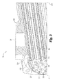
- Forming the turbulators 204 from SMA provides the ability for the system to operate in a "cold" (FCC) state with very little turbulence, hence making the heat exchanger act more as a pipe with little pressure drop (See Fig. 3 .)
- FCC cold
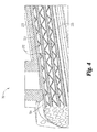
- the SMA turbulator strip 204 changes to the "warm" (BC) state, in which SMA turbulator strip 204 acts as a turbulator (as shown in Fig. 4 ).
- BC warm state
- SMA turbulator strip 204 creates greater turbulence in the oil, resulting in increased heat transfer to the tubes 202 and surrounding coolant.
- the SMA turbulator strip 204 is shaped in a substantially V-shaped pattern having a repeating first leg 221 extending one direction and a second leg 223 extending in divergent direction from a vertex point 225.
- one or more of the vertex points 225 can engage with an inner surface of one or more of the walls of the tubes 202.
- vertex points 225 remain free from engagement with internal portions of the tubes 202 when in the warm state.
- SMA turbulator strip 204 may be of another configuration when in the warm state (such as twisted-tape or corkscrew).
- SMA turbulator strip 204 is configured to increase turbulence when in the warm state, although it is also contemplated that SMA turbulator strip 204 may be configured to increase turbulence when in the cold state in some embodiments. In either case, SMA turbulator strip 204 causes increased turbulence when in one of the warm state and the cold state, and reduced turbulence when in the other of the warm state and the cold state.
- an alternate compressor system 10b is shown which is similar to the embodiment of Fig. 2 , but without a thermal mixing valve. Incorporation of an SMA enhanced heat exchanger 76 can permit removal of the TCV and associated components in some embodiments.
- the compressor system 10b provides for a simplified system leading to a cost savings in both initial manufacturing and assembly of the system as well as future savings in reduced maintenance expenses.
- the SMA turbulator strip(s) 204 When the oil is relatively cold (for example during compressor start-up or very cold ambient temperatures), the SMA turbulator strip(s) 204 will be in the cold state ( Fig. 3 ), in which oil flows through the tubes 202 with little turbulence. This results in a reduced heat transfer coefficient, and less heat being transferred from the oil. Thus, the oil is returned to the compressor 30 while having lost relatively little heat.
- the SMA turbulator strip 204 will be in a transitional configuration as it transforms from the cold state to the warm state. The turbulence, and thus the heat transfer coefficient, increase as the SMA turbulator strip(s) 204 transforms from the cold state to the warm state.
- the SMA turbulator strip 204 transforms to the warm state ( Fig. 4 ), in which the turbulence of the oil flowing through the oil cooler 76 is greatly increased. This results in an increased heat transfer coefficient, and more heat being transferred from the oil. Thus, the oil is returned to the compressor after being significantly cooled.
- the compressor system 10b does not require additional components to sense temperature changes and drive valves or other devices as required with system 10a where the thermal control valve works in conjunction with the heat exchanger. These additional components create greater complexity, cost, and reliability issues. By eliminating such components, system 10b may be simplified and become more reliable.
- Fig. 7 illustrates exemplary performance curves for the conventional system operating with a TCV (long dashes), the conventional system operating without a TCV (short dashes), and the system utilizing the thermally active heat exchanger 76 without a TCV (solid line). While operating the conventional system without the TCV results in an increased heat transfer coefficient as compared to operating the system with the TCV, doing so can result in the undesired consequences detailed above (e.g. improper lubrication or decreased system efficiency).
- the heat exchanger performance it may be desirable to 'tune' the heat exchanger performance to the desired function and operating conditions of the compressor. For example, reducing the ability of the heat exchanger to transfer heat when the oil is cold can be achieved by reducing the length and/or number of tubes in it, thereby reducing cost. Since the turbulators actively generate turbulence to induce the required heat transfer in the hot condition, it is may be desirable to reduce the size of the thermally active heat exchanger with SMA turbulator strips 204 in order to reduce the cost, for example by reducing the length and/or number of tubes. With this optimization, the SMA oil cooler can achieve results similar to a standard oil cooler with a thermal control valve system, while still taking advantage of the reduced cost and simplicity of such a system. If further reductions in the heat transfer are required for the colder temperature region, a coolant flow control valve can be added to increase coolant flow rate (not shown in the drawing) as one skilled in the art would readily understand.
- Fig. 8 illustrates example performance curves of an optimized system with a 20% reduction in tubes (solid line) as compared to the conventional system operating with a TCV. Further “tuning” can result in a desired combination of UA (heat transfer coefficient and effective flow area) to produce an optimum system.
- the compressor system is configured to provide compressed air at a desired temperature and pressure to external systems.
- the compressor systems can be used in any industrial application including, but not limited to automobile manufacturing, textile manufacturing, process industries, refineries, power plants, mining, material handling, etc.
- the controller permits user input to define parameters such as pressure, temperature and mass flow rate of various working fluids.
- the controller will send command signals to the motor to rotate at a desired operating speed in order to drive the one or more compressors and control various valving to modulate airflow rate, coolant flow rate and/or lubrication flow rates.
- the compressor system includes a single-stage screw type compressor system, however, the system can operate with other types of compressors and/or with more or less stages of compressors.
- One or more intercoolers can be fluidly coupled to each compressor stage such that after air is compressed through a compression stage the air can be transported through an intercooler coupled to an open or a closed loop cooling system and cooled to a desired temperature via a heat transfer mechanism such as conduction and convection in tube type heat exchangers.
- the compressed air can then be transported to additional compressor stages where the air is further compressed and necessarily heated to a higher temperature through a thermodynamic process.
- the compressed air can then be routed through subsequent intercooler stages coupled to the closed loop water cooling system to cool the air to a desired temperature without substantial loss of pressure.
- the compressed air is discharged to a final subsystem or end load.
- a thermally active heat exchanger with an SMA member that operates as a turbulator strip at a predefined threshold temperature can be used to cool oil to a desired temperature prior to entering into the compressor system.
- the present disclosure includes a compressor system comprising at least one fluid compressor for compressing a working fluid; a lubrication supply system operable for supplying lubrication fluid to the compressor; a heat exchanger for controlling the temperature of the lubrication, the heat exchanger comprising an outer shell housing a plurality of lubrication fluid passageways; at least one cooling fluid passageway in thermal contact with the plurality of lubrication fluid passageways; a shaped memory allow (SMA) member positioned within at least one of the plurality of lubrication fluid passageways and wherein the SMA member is substantially formed as an elongate flat plate below a first threshold temperature.
- a compressor system comprising at least one fluid compressor for compressing a working fluid; a lubrication supply system operable for supplying lubrication fluid to the compressor; a heat exchanger for controlling the temperature of the lubrication, the heat exchanger comprising an outer shell housing a plurality of lubrication fluid passageways; at least one cooling fluid passageway in thermal contact with
- the present disclosure system includes a compressor system wherein the SMA member includes portions formed in a substantially V-shaped pattern above a second threshold temperature; wherein the SMA member includes portions formed in an intermediate pattern between the flat plate and the V-shaped pattern at temperatures between the first and second threshold temperatures; wherein at least a portion of the substantially V-shaped SMA member engages with an internal wall of a corresponding lubrication passage way above the second threshold temperature; at least one bypass conduit for bypassing lubrication fluid past the heat exchanger; at least one mixing valve downstream of the heat exchanger and the bypass conduit to control mixing of lubrication fluid from the heat exchanger and the bypass conduit; wherein at least one of the SMA members is free from mechanical connection with a corresponding lubrication fluid passageway; wherein at least one SMA member is mechanically connected in at least one location to an internal wall of an associated lubrication fluid passageway; wherein at least one of the SMA members includes a recessed portion within a wall thereof and wherein at least one SMA member includes
- the present disclosure includes a lubrication cooler comprising a housing having a plurality of lubrication fluid passageways positioned therethrough; at least one cooling fluid passageway in thermal communication with the plurality of lubrication fluid passageways; a shape memory alloy (SMA) member extending at least partially through at least one of the plurality of lubrication fluid passageways and wherein the SMA member is configured as an elongate substantially flat plate below a first threshold temperature and includes a memory shape configured as a turbulator above a second threshold temperature.
- SMA shape memory alloy
- the present disclosure includes a lubrication cooler wherein the SMA member includes a substantially V-shaped pattern when configured as a turbulator; wherein the SMA member includes portions formed in shape that is different from the flat plate and the V-shaped pattern at temperatures between the first and second threshold temperatures; wherein the SMA member is configured to increase turbulence of the lubrication fluid as the operating temperature increases; further comprising a plurality of SMA members positioned in at least one of the lubrication fluid passageways; wherein the plurality of SMA members extend parallel to one another along the length of at least one of the lubrication fluid passageways and wherein the SMA member engages an internal wall along portions of a corresponding lubrication passage when formed as a turbulator above the second threshold temperature.
- the present disclosure includes a method comprising compressing a working fluid with a compression device; separating lubrication fluid and air from the working fluid; cooling the lubrication fluid with a heat exchanger; changing a shape of a turbulator positioned in the heat exchanger in response to a temperature change of the lubrication fluid; increasing the turbulence of the lubrication fluid with the turbulator in the heat exchanger as the operating temperature of the lubrication fluid increases and wherein the shape of the turbulator changes to a substantially V-shaped pattern configuration above a predefined temperature threshold.
- the present disclosure includes a method wherein the turbulator is substantially flat below the predefined temperature threshold; controlling a flow rate of the lubrication fluid through the heat exchanger with the turbulator.
Landscapes
- Engineering & Computer Science (AREA)
- General Engineering & Computer Science (AREA)
- Mechanical Engineering (AREA)
- Physics & Mathematics (AREA)
- Thermal Sciences (AREA)
- Geometry (AREA)
- Structures Of Non-Positive Displacement Pumps (AREA)
- Compressor (AREA)
- Fluid Mechanics (AREA)
- Applications Or Details Of Rotary Compressors (AREA)
- Heat-Exchange Devices With Radiators And Conduit Assemblies (AREA)
Applications Claiming Priority (1)
| Application Number | Priority Date | Filing Date | Title |
|---|---|---|---|
| US201361868074P | 2013-08-20 | 2013-08-20 |
Publications (3)
| Publication Number | Publication Date |
|---|---|
| EP2860401A2 true EP2860401A2 (de) | 2015-04-15 |
| EP2860401A3 EP2860401A3 (de) | 2015-05-06 |
| EP2860401B1 EP2860401B1 (de) | 2016-06-01 |
Family
ID=51392093
Family Applications (1)
| Application Number | Title | Priority Date | Filing Date |
|---|---|---|---|
| EP14181567.0A Not-in-force EP2860401B1 (de) | 2013-08-20 | 2014-08-20 | Kompressorsystem mit thermisch aktivem Wärmetauscher |
Country Status (3)
| Country | Link |
|---|---|
| US (1) | US10359240B2 (de) |
| EP (1) | EP2860401B1 (de) |
| CN (1) | CN104454461B (de) |
Cited By (12)
| Publication number | Priority date | Publication date | Assignee | Title |
|---|---|---|---|---|
| EP3199902A1 (de) * | 2016-01-27 | 2017-08-02 | Honeywell International Inc. | Bimetallische rippe mit wärmeanpassender verwirbelungsfunktion |
| FR3064735A1 (fr) * | 2017-04-03 | 2018-10-05 | Valeo Systemes Thermiques | Dispositif d’echange thermique pour vehicule automobile |
| EP3531227A1 (de) * | 2018-02-21 | 2019-08-28 | The Boeing Company | Wärmeverwaltungssysteme mit formgedächtnislegierungsaktuatoren und zugehörige verfahren |
| WO2020257914A1 (en) * | 2019-06-28 | 2020-12-30 | Leggett & Platt Canada Co. | Fluid management system |
| US11028937B2 (en) | 2016-12-29 | 2021-06-08 | L&P Property Management Company | Valve with shape memory alloy wire |
| US11525438B2 (en) | 2019-06-28 | 2022-12-13 | The Boeing Company | Shape memory alloy actuators and thermal management systems including the same |
| US11808374B2 (en) | 2020-12-30 | 2023-11-07 | Leggett & Platt Canada Co. | Fluid management system |
| US12085185B2 (en) | 2020-02-24 | 2024-09-10 | Schukra Berndorf Gmbh | Electrically actuated valves |
| US12146583B2 (en) | 2019-08-09 | 2024-11-19 | Leggett & Platt Canada Co. | Latching valve |
| US12247562B2 (en) | 2019-11-01 | 2025-03-11 | Leggett & Platt Canada Co. | Pump noise attenuator and method thereof |
| US12338812B2 (en) | 2019-11-01 | 2025-06-24 | Leggett & Platt Canada Co. | Pump noise attenuator and method thereof |
| US12545166B2 (en) | 2019-02-19 | 2026-02-10 | Schukra Berndorf Gmbh | Fluid valve module, fluid valve system and methods of producing the same |
Families Citing this family (7)
| Publication number | Priority date | Publication date | Assignee | Title |
|---|---|---|---|---|
| DE102017002601A1 (de) * | 2017-03-17 | 2018-09-20 | Man Truck & Bus Ag | Kühlvorrichtung für elektronisches Steuergerät |
| DE102017107933A1 (de) * | 2017-04-12 | 2018-10-18 | Knorr-Bremse Systeme für Nutzfahrzeuge GmbH | Kompressorsystem mit regelbarer und/oder steuerbarer Temperaturüberwachungs-einrichtung |
| US10851786B2 (en) * | 2017-09-27 | 2020-12-01 | Ingersoll-Rand Industrial U.S., Inc. | Rotary screw compressor with atomized oil injection |
| US11215182B2 (en) * | 2018-03-01 | 2022-01-04 | Ingersoll-Rand Industrial U.S., Inc. | Multi-stage compressor having interstage lubricant injection via an injection rod |
| CN108643975A (zh) * | 2018-03-22 | 2018-10-12 | 南京航空航天大学 | 一种利用记忆合金提高气膜冷却效率的结构 |
| GB2596275A (en) * | 2020-05-20 | 2021-12-29 | Edwards Ltd | Cooling element |
| CN112097545A (zh) * | 2020-07-28 | 2020-12-18 | 厦门大学 | 一种内置记忆合金弹簧的智能细通道换热器 |
Family Cites Families (34)
| Publication number | Priority date | Publication date | Assignee | Title |
|---|---|---|---|---|
| US2161887A (en) * | 1938-01-07 | 1939-06-13 | Young Radiator Co | Turbulence strip for radiator tubes |
| US4044796A (en) * | 1976-02-09 | 1977-08-30 | Smick Ronald H | Turbulator |
| US4296779A (en) * | 1979-10-09 | 1981-10-27 | Smick Ronald H | Turbulator with ganged strips |
| JPS58182096A (ja) * | 1982-04-19 | 1983-10-24 | Nissan Motor Co Ltd | アルミニウム製の熱交換器 |
| JPS59231397A (ja) * | 1983-06-10 | 1984-12-26 | Matsushita Refrig Co | タ−ビユレ−タ |
| JPS63134268U (de) | 1987-02-13 | 1988-09-02 | ||
| US4727907A (en) * | 1987-03-30 | 1988-03-01 | Dunham-Bush | Turbulator with integral flow deflector tabs |
| US4841730A (en) | 1987-07-02 | 1989-06-27 | Pda Engineering | Thermal actuator |
| JPH01121694A (ja) * | 1987-11-02 | 1989-05-15 | Sanyo Electric Co Ltd | 熱交換器用熱媒管 |
| JPH01131897A (ja) * | 1987-11-18 | 1989-05-24 | Hitachi Ltd | 多管式熱交換器 |
| US5369883A (en) * | 1989-02-24 | 1994-12-06 | Long Manufacturing Ltd. | Method for making an in tank oil cooler |
| EP0655275B1 (de) * | 1993-11-26 | 1999-10-06 | Sulzer Chemtech AG | Statische Mischvorrichtung |
| US6273183B1 (en) * | 1997-08-29 | 2001-08-14 | Long Manufacturing Ltd. | Heat exchanger turbulizers with interrupted convolutions |
| JPH1194362A (ja) * | 1997-09-24 | 1999-04-09 | Sanyo Electric Co Ltd | 熱交換器 |
| US6186223B1 (en) | 1998-08-27 | 2001-02-13 | Zeks Air Drier Corporation | Corrugated folded plate heat exchanger |
| US6244333B1 (en) | 1998-08-27 | 2001-06-12 | Zeks Air Drier Corporation | Corrugated folded plate heat exchanger |
| IT1320693B1 (it) | 2000-10-06 | 2003-12-10 | Fiat Ricerche | Dispositivo per la regolazione di un flusso d'aria in un condotto, con attuatore a memoria di forma integrato, particolarmente per sistemi |
| US6699015B2 (en) | 2002-02-19 | 2004-03-02 | The Boeing Company | Blades having coolant channels lined with a shape memory alloy and an associated fabrication method |
| US6962193B2 (en) * | 2002-04-09 | 2005-11-08 | Honeywell Interntaional Inc. | Tubular catalytic aircraft precooler |
| KR20060005403A (ko) | 2003-04-28 | 2006-01-17 | 나노머슬, 인크. | 일체로 형성된 형상 기억 합금 액츄에이터를 갖는 유동제어 조립체 |
| US7506735B2 (en) * | 2004-06-14 | 2009-03-24 | William Marsh Rice University | Vibration damping and heat transfer using material phase changes |
| JP4363283B2 (ja) | 2004-09-13 | 2009-11-11 | 株式会社デンソー | 空気通路開閉装置 |
| US7540431B2 (en) | 2004-11-24 | 2009-06-02 | Dana Canada Corporation | By-pass valve for heat exchanger |
| JP2006266514A (ja) * | 2005-03-22 | 2006-10-05 | Matsushita Electric Ind Co Ltd | 熱交換器 |
| JP2008096048A (ja) * | 2006-10-13 | 2008-04-24 | Tokyo Radiator Mfg Co Ltd | 排気ガス用熱交換器のインナーフィン |
| US20080099193A1 (en) | 2006-11-01 | 2008-05-01 | Slavek Peter Aksamit | Self-regulated cooling mechanism |
| US20090200007A1 (en) | 2008-02-13 | 2009-08-13 | Lockheed Martin Corporation | Heat exchanger having temperature-actuated valves |
| JP2010216712A (ja) * | 2009-03-16 | 2010-09-30 | Tokyo Electric Power Co Inc:The | ヒートパイプ |
| EP2526297B1 (de) * | 2010-01-22 | 2016-04-20 | Ingersoll-Rand Company | Verdichtersystem mit durchfluss- und temperaturregler |
| JP5244845B2 (ja) * | 2010-03-31 | 2013-07-24 | 株式会社ユタカ技研 | 熱交換器 |
| DE102010022225A1 (de) * | 2010-04-28 | 2011-12-15 | J. Eberspächer GmbH & Co. KG | Wärmeübertragungsanordnung, Wärmeübertrager und Herstellungsverfahren |
| CN202836281U (zh) * | 2012-09-27 | 2013-03-27 | 常州新奥燃气工程有限公司 | 压缩机所用换热器 |
| US20140102673A1 (en) * | 2012-10-11 | 2014-04-17 | Carrier Corporation | Heat transfer enhancement for a condensing furnace |
| WO2016121949A1 (ja) * | 2015-01-30 | 2016-08-04 | 秀之 春山 | 流体熱交換ミキシング移送装置 |
-
2014
- 2014-08-19 US US14/463,091 patent/US10359240B2/en not_active Expired - Fee Related
- 2014-08-20 CN CN201410557670.3A patent/CN104454461B/zh not_active Expired - Fee Related
- 2014-08-20 EP EP14181567.0A patent/EP2860401B1/de not_active Not-in-force
Non-Patent Citations (1)
| Title |
|---|
| "ASM Handbook", vol. 2, 1990, ASM INTERNATIONAL, article "Properties and Selection: Nonferrous Alloys and Special-Purpose Materials" |
Cited By (16)
| Publication number | Priority date | Publication date | Assignee | Title |
|---|---|---|---|---|
| EP3199902A1 (de) * | 2016-01-27 | 2017-08-02 | Honeywell International Inc. | Bimetallische rippe mit wärmeanpassender verwirbelungsfunktion |
| US10113818B2 (en) | 2016-01-27 | 2018-10-30 | Garrett Transportation I Inc. | Bimetallic fin with themo-adjusting turbulation feature |
| US11028937B2 (en) | 2016-12-29 | 2021-06-08 | L&P Property Management Company | Valve with shape memory alloy wire |
| FR3064735A1 (fr) * | 2017-04-03 | 2018-10-05 | Valeo Systemes Thermiques | Dispositif d’echange thermique pour vehicule automobile |
| WO2018185410A1 (fr) * | 2017-04-03 | 2018-10-11 | Valeo Systemes Thermiques | Dispositif d'échange thermique pour véhicule automobile |
| EP3531227A1 (de) * | 2018-02-21 | 2019-08-28 | The Boeing Company | Wärmeverwaltungssysteme mit formgedächtnislegierungsaktuatoren und zugehörige verfahren |
| US10612867B2 (en) | 2018-02-21 | 2020-04-07 | The Boeing Company | Thermal management systems incorporating shape memory alloy actuators and related methods |
| US12545166B2 (en) | 2019-02-19 | 2026-02-10 | Schukra Berndorf Gmbh | Fluid valve module, fluid valve system and methods of producing the same |
| US11525438B2 (en) | 2019-06-28 | 2022-12-13 | The Boeing Company | Shape memory alloy actuators and thermal management systems including the same |
| US12104703B2 (en) | 2019-06-28 | 2024-10-01 | Leggett & Platt Canada Co. | Fluid management system |
| WO2020257914A1 (en) * | 2019-06-28 | 2020-12-30 | Leggett & Platt Canada Co. | Fluid management system |
| US12146583B2 (en) | 2019-08-09 | 2024-11-19 | Leggett & Platt Canada Co. | Latching valve |
| US12247562B2 (en) | 2019-11-01 | 2025-03-11 | Leggett & Platt Canada Co. | Pump noise attenuator and method thereof |
| US12338812B2 (en) | 2019-11-01 | 2025-06-24 | Leggett & Platt Canada Co. | Pump noise attenuator and method thereof |
| US12085185B2 (en) | 2020-02-24 | 2024-09-10 | Schukra Berndorf Gmbh | Electrically actuated valves |
| US11808374B2 (en) | 2020-12-30 | 2023-11-07 | Leggett & Platt Canada Co. | Fluid management system |
Also Published As
| Publication number | Publication date |
|---|---|
| US10359240B2 (en) | 2019-07-23 |
| EP2860401B1 (de) | 2016-06-01 |
| CN104454461A (zh) | 2015-03-25 |
| US20150053390A1 (en) | 2015-02-26 |
| EP2860401A3 (de) | 2015-05-06 |
| CN104454461B (zh) | 2018-11-06 |
Similar Documents
| Publication | Publication Date | Title |
|---|---|---|
| EP2860401B1 (de) | Kompressorsystem mit thermisch aktivem Wärmetauscher | |
| US10746177B2 (en) | Compressor with a closed loop water cooling system | |
| RU2709761C2 (ru) | Охлаждение масляного контура турбинного двигателя | |
| CA2973008A1 (en) | Compressor system and lubricant control valve | |
| US12117001B2 (en) | Screw compressor with oil injection at multiple volume ratios | |
| US10240602B2 (en) | Compressor system and method for conditioning inlet air | |
| US10208754B2 (en) | Oil flooded compressor system and method | |
| EP3084217B1 (de) | Verfahren zur verbesserung der zuverlässigkeit von verdichterlagern | |
| CN101576337A (zh) | 智能油路控制系统 | |
| JP3250957U (ja) | 改良されたオイルインジェクタを備える圧縮機要素 | |
| KR101360224B1 (ko) | 터보 냉동기용 오일 냉각 시스템 | |
| CN212431383U (zh) | 冷水机组 | |
| CN113686037A (zh) | 冷水机组 | |
| CN204438580U (zh) | 一种海水变流量冷藏系统 | |
| KR101204075B1 (ko) | 오일쿨러 내장형 오일탱크 구조 | |
| BE1017320A3 (nl) | Vloeistofgeinjecteerde compressorinstallatie. | |
| CN100557336C (zh) | 一种致冷剂系统以及控制该系统中的操作压力的方法 | |
| CN223580294U (zh) | 一种带喷雾油冷的制冷系统 | |
| CN214701319U (zh) | 一种制冷系统及空调系统 | |
| US20130037243A1 (en) | Thermodynamic Device For Refrigeration And Air Conditioning | |
| CN205823578U (zh) | 一种压缩机系统 | |
| CN121066834A (zh) | 压缩机系统及热泵系统 | |
| US10851785B2 (en) | Compressor system with variable blowdown control | |
| CN118128937A (zh) | 用于高温环境金属对金属密封区域的流体流量控制阀 | |
| Petrecca | Facilities: Gas Compressors |
Legal Events
| Date | Code | Title | Description |
|---|---|---|---|
| PUAL | Search report despatched |
Free format text: ORIGINAL CODE: 0009013 |
|
| PUAI | Public reference made under article 153(3) epc to a published international application that has entered the european phase |
Free format text: ORIGINAL CODE: 0009012 |
|
| 17P | Request for examination filed |
Effective date: 20140820 |
|
| AK | Designated contracting states |
Kind code of ref document: A2 Designated state(s): AL AT BE BG CH CY CZ DE DK EE ES FI FR GB GR HR HU IE IS IT LI LT LU LV MC MK MT NL NO PL PT RO RS SE SI SK SM TR |
|
| AX | Request for extension of the european patent |
Extension state: BA ME |
|
| AK | Designated contracting states |
Kind code of ref document: A3 Designated state(s): AL AT BE BG CH CY CZ DE DK EE ES FI FR GB GR HR HU IE IS IT LI LT LU LV MC MK MT NL NO PL PT RO RS SE SI SK SM TR |
|
| AX | Request for extension of the european patent |
Extension state: BA ME |
|
| RIC1 | Information provided on ipc code assigned before grant |
Ipc: F04C 29/02 20060101AFI20150330BHEP Ipc: F04C 29/04 20060101ALI20150330BHEP Ipc: F28F 13/12 20060101ALI20150330BHEP Ipc: F28F 1/40 20060101ALI20150330BHEP |
|
| REG | Reference to a national code |
Ref country code: DE Ref legal event code: R079 Ref document number: 602014002177 Country of ref document: DE Free format text: PREVIOUS MAIN CLASS: F04C0029020000 Ipc: F16N0039020000 |
|
| GRAP | Despatch of communication of intention to grant a patent |
Free format text: ORIGINAL CODE: EPIDOSNIGR1 |
|
| RIC1 | Information provided on ipc code assigned before grant |
Ipc: F28D 7/16 20060101ALI20151126BHEP Ipc: F04C 29/02 20060101ALI20151126BHEP Ipc: F28D 21/00 20060101ALI20151126BHEP Ipc: F16N 39/02 20060101AFI20151126BHEP Ipc: F28F 13/12 20060101ALI20151126BHEP Ipc: F28F 1/40 20060101ALI20151126BHEP |
|
| INTG | Intention to grant announced |
Effective date: 20151221 |
|
| GRAS | Grant fee paid |
Free format text: ORIGINAL CODE: EPIDOSNIGR3 |
|
| GRAA | (expected) grant |
Free format text: ORIGINAL CODE: 0009210 |
|
| AK | Designated contracting states |
Kind code of ref document: B1 Designated state(s): AL AT BE BG CH CY CZ DE DK EE ES FI FR GB GR HR HU IE IS IT LI LT LU LV MC MK MT NL NO PL PT RO RS SE SI SK SM TR |
|
| REG | Reference to a national code |
Ref country code: GB Ref legal event code: FG4D |
|
| REG | Reference to a national code |
Ref country code: CH Ref legal event code: EP Ref country code: AT Ref legal event code: REF Ref document number: 804100 Country of ref document: AT Kind code of ref document: T Effective date: 20160615 |
|
| REG | Reference to a national code |
Ref country code: IE Ref legal event code: FG4D |
|
| REG | Reference to a national code |
Ref country code: DE Ref legal event code: R096 Ref document number: 602014002177 Country of ref document: DE |
|
| REG | Reference to a national code |
Ref country code: LT Ref legal event code: MG4D |
|
| REG | Reference to a national code |
Ref country code: NL Ref legal event code: MP Effective date: 20160601 |
|
| PG25 | Lapsed in a contracting state [announced via postgrant information from national office to epo] |
Ref country code: LT Free format text: LAPSE BECAUSE OF FAILURE TO SUBMIT A TRANSLATION OF THE DESCRIPTION OR TO PAY THE FEE WITHIN THE PRESCRIBED TIME-LIMIT Effective date: 20160601 Ref country code: NO Free format text: LAPSE BECAUSE OF FAILURE TO SUBMIT A TRANSLATION OF THE DESCRIPTION OR TO PAY THE FEE WITHIN THE PRESCRIBED TIME-LIMIT Effective date: 20160901 Ref country code: FI Free format text: LAPSE BECAUSE OF FAILURE TO SUBMIT A TRANSLATION OF THE DESCRIPTION OR TO PAY THE FEE WITHIN THE PRESCRIBED TIME-LIMIT Effective date: 20160601 |
|
| REG | Reference to a national code |
Ref country code: AT Ref legal event code: MK05 Ref document number: 804100 Country of ref document: AT Kind code of ref document: T Effective date: 20160601 |
|
| PG25 | Lapsed in a contracting state [announced via postgrant information from national office to epo] |
Ref country code: SE Free format text: LAPSE BECAUSE OF FAILURE TO SUBMIT A TRANSLATION OF THE DESCRIPTION OR TO PAY THE FEE WITHIN THE PRESCRIBED TIME-LIMIT Effective date: 20160601 Ref country code: HR Free format text: LAPSE BECAUSE OF FAILURE TO SUBMIT A TRANSLATION OF THE DESCRIPTION OR TO PAY THE FEE WITHIN THE PRESCRIBED TIME-LIMIT Effective date: 20160601 Ref country code: LV Free format text: LAPSE BECAUSE OF FAILURE TO SUBMIT A TRANSLATION OF THE DESCRIPTION OR TO PAY THE FEE WITHIN THE PRESCRIBED TIME-LIMIT Effective date: 20160601 Ref country code: GR Free format text: LAPSE BECAUSE OF FAILURE TO SUBMIT A TRANSLATION OF THE DESCRIPTION OR TO PAY THE FEE WITHIN THE PRESCRIBED TIME-LIMIT Effective date: 20160902 Ref country code: NL Free format text: LAPSE BECAUSE OF FAILURE TO SUBMIT A TRANSLATION OF THE DESCRIPTION OR TO PAY THE FEE WITHIN THE PRESCRIBED TIME-LIMIT Effective date: 20160601 Ref country code: RS Free format text: LAPSE BECAUSE OF FAILURE TO SUBMIT A TRANSLATION OF THE DESCRIPTION OR TO PAY THE FEE WITHIN THE PRESCRIBED TIME-LIMIT Effective date: 20160601 Ref country code: ES Free format text: LAPSE BECAUSE OF FAILURE TO SUBMIT A TRANSLATION OF THE DESCRIPTION OR TO PAY THE FEE WITHIN THE PRESCRIBED TIME-LIMIT Effective date: 20160601 |
|
| PG25 | Lapsed in a contracting state [announced via postgrant information from national office to epo] |
Ref country code: CZ Free format text: LAPSE BECAUSE OF FAILURE TO SUBMIT A TRANSLATION OF THE DESCRIPTION OR TO PAY THE FEE WITHIN THE PRESCRIBED TIME-LIMIT Effective date: 20160601 Ref country code: SK Free format text: LAPSE BECAUSE OF FAILURE TO SUBMIT A TRANSLATION OF THE DESCRIPTION OR TO PAY THE FEE WITHIN THE PRESCRIBED TIME-LIMIT Effective date: 20160601 Ref country code: EE Free format text: LAPSE BECAUSE OF FAILURE TO SUBMIT A TRANSLATION OF THE DESCRIPTION OR TO PAY THE FEE WITHIN THE PRESCRIBED TIME-LIMIT Effective date: 20160601 Ref country code: RO Free format text: LAPSE BECAUSE OF FAILURE TO SUBMIT A TRANSLATION OF THE DESCRIPTION OR TO PAY THE FEE WITHIN THE PRESCRIBED TIME-LIMIT Effective date: 20160601 Ref country code: IT Free format text: LAPSE BECAUSE OF FAILURE TO SUBMIT A TRANSLATION OF THE DESCRIPTION OR TO PAY THE FEE WITHIN THE PRESCRIBED TIME-LIMIT Effective date: 20160601 Ref country code: IS Free format text: LAPSE BECAUSE OF FAILURE TO SUBMIT A TRANSLATION OF THE DESCRIPTION OR TO PAY THE FEE WITHIN THE PRESCRIBED TIME-LIMIT Effective date: 20161001 |
|
| PG25 | Lapsed in a contracting state [announced via postgrant information from national office to epo] |
Ref country code: PL Free format text: LAPSE BECAUSE OF FAILURE TO SUBMIT A TRANSLATION OF THE DESCRIPTION OR TO PAY THE FEE WITHIN THE PRESCRIBED TIME-LIMIT Effective date: 20160601 Ref country code: AT Free format text: LAPSE BECAUSE OF FAILURE TO SUBMIT A TRANSLATION OF THE DESCRIPTION OR TO PAY THE FEE WITHIN THE PRESCRIBED TIME-LIMIT Effective date: 20160601 Ref country code: SM Free format text: LAPSE BECAUSE OF FAILURE TO SUBMIT A TRANSLATION OF THE DESCRIPTION OR TO PAY THE FEE WITHIN THE PRESCRIBED TIME-LIMIT Effective date: 20160601 Ref country code: PT Free format text: LAPSE BECAUSE OF FAILURE TO SUBMIT A TRANSLATION OF THE DESCRIPTION OR TO PAY THE FEE WITHIN THE PRESCRIBED TIME-LIMIT Effective date: 20161003 |
|
| REG | Reference to a national code |
Ref country code: DE Ref legal event code: R097 Ref document number: 602014002177 Country of ref document: DE |
|
| PG25 | Lapsed in a contracting state [announced via postgrant information from national office to epo] |
Ref country code: MC Free format text: LAPSE BECAUSE OF FAILURE TO SUBMIT A TRANSLATION OF THE DESCRIPTION OR TO PAY THE FEE WITHIN THE PRESCRIBED TIME-LIMIT Effective date: 20160601 |
|
| PLBE | No opposition filed within time limit |
Free format text: ORIGINAL CODE: 0009261 |
|
| STAA | Information on the status of an ep patent application or granted ep patent |
Free format text: STATUS: NO OPPOSITION FILED WITHIN TIME LIMIT |
|
| 26N | No opposition filed |
Effective date: 20170302 |
|
| REG | Reference to a national code |
Ref country code: FR Ref legal event code: ST Effective date: 20170428 |
|
| PG25 | Lapsed in a contracting state [announced via postgrant information from national office to epo] |
Ref country code: DK Free format text: LAPSE BECAUSE OF FAILURE TO SUBMIT A TRANSLATION OF THE DESCRIPTION OR TO PAY THE FEE WITHIN THE PRESCRIBED TIME-LIMIT Effective date: 20160601 Ref country code: SI Free format text: LAPSE BECAUSE OF FAILURE TO SUBMIT A TRANSLATION OF THE DESCRIPTION OR TO PAY THE FEE WITHIN THE PRESCRIBED TIME-LIMIT Effective date: 20160601 |
|
| REG | Reference to a national code |
Ref country code: IE Ref legal event code: MM4A |
|
| PG25 | Lapsed in a contracting state [announced via postgrant information from national office to epo] |
Ref country code: FR Free format text: LAPSE BECAUSE OF NON-PAYMENT OF DUE FEES Effective date: 20160831 Ref country code: IE Free format text: LAPSE BECAUSE OF NON-PAYMENT OF DUE FEES Effective date: 20160820 |
|
| PG25 | Lapsed in a contracting state [announced via postgrant information from national office to epo] |
Ref country code: LU Free format text: LAPSE BECAUSE OF NON-PAYMENT OF DUE FEES Effective date: 20160820 |
|
| REG | Reference to a national code |
Ref country code: CH Ref legal event code: PL |
|
| PG25 | Lapsed in a contracting state [announced via postgrant information from national office to epo] |
Ref country code: CH Free format text: LAPSE BECAUSE OF NON-PAYMENT OF DUE FEES Effective date: 20170831 Ref country code: LI Free format text: LAPSE BECAUSE OF NON-PAYMENT OF DUE FEES Effective date: 20170831 |
|
| PG25 | Lapsed in a contracting state [announced via postgrant information from national office to epo] |
Ref country code: HU Free format text: LAPSE BECAUSE OF FAILURE TO SUBMIT A TRANSLATION OF THE DESCRIPTION OR TO PAY THE FEE WITHIN THE PRESCRIBED TIME-LIMIT; INVALID AB INITIO Effective date: 20140820 |
|
| PG25 | Lapsed in a contracting state [announced via postgrant information from national office to epo] |
Ref country code: CY Free format text: LAPSE BECAUSE OF FAILURE TO SUBMIT A TRANSLATION OF THE DESCRIPTION OR TO PAY THE FEE WITHIN THE PRESCRIBED TIME-LIMIT Effective date: 20160601 Ref country code: MK Free format text: LAPSE BECAUSE OF FAILURE TO SUBMIT A TRANSLATION OF THE DESCRIPTION OR TO PAY THE FEE WITHIN THE PRESCRIBED TIME-LIMIT Effective date: 20160601 Ref country code: MT Free format text: LAPSE BECAUSE OF NON-PAYMENT OF DUE FEES Effective date: 20160831 |
|
| REG | Reference to a national code |
Ref country code: DE Ref legal event code: R082 Ref document number: 602014002177 Country of ref document: DE Representative=s name: HASELTINE LAKE KEMPNER LLP, DE Ref country code: DE Ref legal event code: R082 Ref document number: 602014002177 Country of ref document: DE Representative=s name: HL KEMPNER PATENTANWALT, RECHTSANWALT, SOLICIT, DE Ref country code: DE Ref legal event code: R082 Ref document number: 602014002177 Country of ref document: DE Representative=s name: MURGITROYD & COMPANY, DE Ref country code: DE Ref legal event code: R082 Ref document number: 602014002177 Country of ref document: DE Representative=s name: HASELTINE LAKE LLP, DE |
|
| PG25 | Lapsed in a contracting state [announced via postgrant information from national office to epo] |
Ref country code: BG Free format text: LAPSE BECAUSE OF FAILURE TO SUBMIT A TRANSLATION OF THE DESCRIPTION OR TO PAY THE FEE WITHIN THE PRESCRIBED TIME-LIMIT Effective date: 20160601 |
|
| PG25 | Lapsed in a contracting state [announced via postgrant information from national office to epo] |
Ref country code: AL Free format text: LAPSE BECAUSE OF FAILURE TO SUBMIT A TRANSLATION OF THE DESCRIPTION OR TO PAY THE FEE WITHIN THE PRESCRIBED TIME-LIMIT Effective date: 20160601 Ref country code: TR Free format text: LAPSE BECAUSE OF FAILURE TO SUBMIT A TRANSLATION OF THE DESCRIPTION OR TO PAY THE FEE WITHIN THE PRESCRIBED TIME-LIMIT Effective date: 20160601 |
|
| GBPC | Gb: european patent ceased through non-payment of renewal fee |
Effective date: 20180820 |
|
| PG25 | Lapsed in a contracting state [announced via postgrant information from national office to epo] |
Ref country code: GB Free format text: LAPSE BECAUSE OF NON-PAYMENT OF DUE FEES Effective date: 20180820 |
|
| REG | Reference to a national code |
Ref country code: BE Ref legal event code: PD Owner name: INGERSOLL-RAND INDUSTRIAL U.S. INC.; US Free format text: DETAILS ASSIGNMENT: CHANGE OF OWNER(S), CESSION, SPLITSING Effective date: 20200415 |
|
| PGFP | Annual fee paid to national office [announced via postgrant information from national office to epo] |
Ref country code: DE Payment date: 20200721 Year of fee payment: 7 |
|
| REG | Reference to a national code |
Ref country code: DE Ref legal event code: R082 Ref document number: 602014002177 Country of ref document: DE Representative=s name: HASELTINE LAKE KEMPNER LLP, DE Ref country code: DE Ref legal event code: R081 Ref document number: 602014002177 Country of ref document: DE Owner name: INGERSOLL-RAND INDUSTRIAL U.S., INC. (N.D.GES., US Free format text: FORMER OWNER: INGERSOLL-RAND COMPANY, DAVIDSON, N.C., US Ref country code: DE Ref legal event code: R082 Ref document number: 602014002177 Country of ref document: DE Representative=s name: HL KEMPNER PATENTANWALT, RECHTSANWALT, SOLICIT, DE Ref country code: DE Ref legal event code: R082 Ref document number: 602014002177 Country of ref document: DE Representative=s name: MURGITROYD & COMPANY, DE |
|
| PGFP | Annual fee paid to national office [announced via postgrant information from national office to epo] |
Ref country code: BE Payment date: 20200724 Year of fee payment: 7 |
|
| REG | Reference to a national code |
Ref country code: DE Ref legal event code: R082 Ref document number: 602014002177 Country of ref document: DE Representative=s name: HL KEMPNER PATENTANWALT, RECHTSANWALT, SOLICIT, DE Ref country code: DE Ref legal event code: R082 Ref document number: 602014002177 Country of ref document: DE Representative=s name: MURGITROYD & COMPANY, DE |
|
| REG | Reference to a national code |
Ref country code: DE Ref legal event code: R082 Ref document number: 602014002177 Country of ref document: DE Representative=s name: MURGITROYD & COMPANY, DE |
|
| REG | Reference to a national code |
Ref country code: DE Ref legal event code: R119 Ref document number: 602014002177 Country of ref document: DE |
|
| REG | Reference to a national code |
Ref country code: BE Ref legal event code: MM Effective date: 20210831 |
|
| PG25 | Lapsed in a contracting state [announced via postgrant information from national office to epo] |
Ref country code: DE Free format text: LAPSE BECAUSE OF NON-PAYMENT OF DUE FEES Effective date: 20220301 Ref country code: BE Free format text: LAPSE BECAUSE OF NON-PAYMENT OF DUE FEES Effective date: 20210831 |