EP2859871A1 - Abschrankungskonstruktion für einen Rollstuhlplatz in einem Fahrzeug - Google Patents
Abschrankungskonstruktion für einen Rollstuhlplatz in einem Fahrzeug Download PDFInfo
- Publication number
- EP2859871A1 EP2859871A1 EP20140002693 EP14002693A EP2859871A1 EP 2859871 A1 EP2859871 A1 EP 2859871A1 EP 20140002693 EP20140002693 EP 20140002693 EP 14002693 A EP14002693 A EP 14002693A EP 2859871 A1 EP2859871 A1 EP 2859871A1
- Authority
- EP
- European Patent Office
- Prior art keywords
- barrier
- shaft
- construction
- barrier construction
- elastic element
- Prior art date
- Legal status (The legal status is an assumption and is not a legal conclusion. Google has not performed a legal analysis and makes no representation as to the accuracy of the status listed.)
- Granted
Links
Images




Classifications
-
- A—HUMAN NECESSITIES
- A61—MEDICAL OR VETERINARY SCIENCE; HYGIENE
- A61G—TRANSPORT, PERSONAL CONVEYANCES, OR ACCOMMODATION SPECIALLY ADAPTED FOR PATIENTS OR DISABLED PERSONS; OPERATING TABLES OR CHAIRS; CHAIRS FOR DENTISTRY; FUNERAL DEVICES
- A61G3/00—Ambulance aspects of vehicles; Vehicles with special provisions for transporting patients or disabled persons, or their personal conveyances, e.g. for facilitating access of, or for loading, wheelchairs
- A61G3/08—Accommodating or securing wheelchairs or stretchers
- A61G3/0808—Accommodating or securing wheelchairs
-
- A—HUMAN NECESSITIES
- A61—MEDICAL OR VETERINARY SCIENCE; HYGIENE
- A61G—TRANSPORT, PERSONAL CONVEYANCES, OR ACCOMMODATION SPECIALLY ADAPTED FOR PATIENTS OR DISABLED PERSONS; OPERATING TABLES OR CHAIRS; CHAIRS FOR DENTISTRY; FUNERAL DEVICES
- A61G3/00—Ambulance aspects of vehicles; Vehicles with special provisions for transporting patients or disabled persons, or their personal conveyances, e.g. for facilitating access of, or for loading, wheelchairs
- A61G3/08—Accommodating or securing wheelchairs or stretchers
-
- B—PERFORMING OPERATIONS; TRANSPORTING
- B60—VEHICLES IN GENERAL
- B60N—SEATS SPECIALLY ADAPTED FOR VEHICLES; VEHICLE PASSENGER ACCOMMODATION NOT OTHERWISE PROVIDED FOR
- B60N2/00—Seats specially adapted for vehicles; Arrangement or mounting of seats in vehicles
- B60N2/24—Seats specially adapted for vehicles; Arrangement or mounting of seats in vehicles for particular purposes or particular vehicles
- B60N2/245—Seats specially adapted for vehicles; Arrangement or mounting of seats in vehicles for particular purposes or particular vehicles for handicapped persons
-
- B—PERFORMING OPERATIONS; TRANSPORTING
- B60—VEHICLES IN GENERAL
- B60N—SEATS SPECIALLY ADAPTED FOR VEHICLES; VEHICLE PASSENGER ACCOMMODATION NOT OTHERWISE PROVIDED FOR
- B60N2/00—Seats specially adapted for vehicles; Arrangement or mounting of seats in vehicles
- B60N2/68—Seat frames
-
- B—PERFORMING OPERATIONS; TRANSPORTING
- B60—VEHICLES IN GENERAL
- B60N—SEATS SPECIALLY ADAPTED FOR VEHICLES; VEHICLE PASSENGER ACCOMMODATION NOT OTHERWISE PROVIDED FOR
- B60N3/00—Arrangements or adaptations of other passenger fittings, not otherwise provided for
- B60N3/02—Arrangements or adaptations of other passenger fittings, not otherwise provided for of hand grips or straps
-
- B—PERFORMING OPERATIONS; TRANSPORTING
- B62—LAND VEHICLES FOR TRAVELLING OTHERWISE THAN ON RAILS
- B62D—MOTOR VEHICLES; TRAILERS
- B62D31/00—Superstructures for passenger vehicles
-
- A—HUMAN NECESSITIES
- A61—MEDICAL OR VETERINARY SCIENCE; HYGIENE
- A61G—TRANSPORT, PERSONAL CONVEYANCES, OR ACCOMMODATION SPECIALLY ADAPTED FOR PATIENTS OR DISABLED PERSONS; OPERATING TABLES OR CHAIRS; CHAIRS FOR DENTISTRY; FUNERAL DEVICES
- A61G3/00—Ambulance aspects of vehicles; Vehicles with special provisions for transporting patients or disabled persons, or their personal conveyances, e.g. for facilitating access of, or for loading, wheelchairs
- A61G3/08—Accommodating or securing wheelchairs or stretchers
- A61G3/0816—Accommodating or securing stretchers
- A61G3/0875—Securing stretchers, e.g. fastening means
- A61G3/0883—Securing stretchers, e.g. fastening means by preventing lateral movement, e.g. tracks
Definitions
- the invention relates to a barrier construction for a wheelchair space in a vehicle, preferably in a bus.
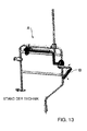
- FIG. 13 shows a perspective view of a barrier structure A for a wheelchair space in a bus according to the prior art.
- the barrier construction A comprises a pivoting or folding barrier device B.
- the barrier device B can be pivoted between a folded-up non-use position and an unfolded position of use, which is indicated by the double arrow in FIG FIG. 13 is indicated schematically.
- Disadvantageous in the FIG. 13 shown Ableungskonstrutation A is that the required pivot or folding mechanism is structurally relatively complex.
- the Abschiereungskonstrutement A includes a variety of protruding parts, which increases the risk of injury or accident and also leads to a visually unappealing appearance.
- An object of the invention is to provide an improved and / or alternative barrier construction for a wheelchair space of a vehicle, in particular a bus.
- the invention provides a barrier construction for a wheelchair space in a vehicle, preferably in a bus.
- the Abhalteungskonstrutation comprises an upper part and a lower part for appropriately fixed, direct or indirect mounting to the vehicle and a barrier device which is connected to the upper part and the lower part.
- the obstruction device is characterized in particular by the fact that it is displaceable relative to the upper part and the lower part translationally in a retracted position (non-use position) and one or more extended positions (use position (s)).
- the barrier device is expedient displaceable in the vehicle transverse direction.
- the barrier device is infinitely displaceable.
- the barrier device is preferably displaceable along a slot.
- a stop for example a grub screw
- the slot thus expediently defines the adjustment path of the barrier device.
- the barrier construction has a rotatable shaft.
- the shaft is preferably rotatable to actuate a fixture for fixing the obstruction means in the retracted position and in an extended position relative to the bonnet or base, e.g. to activate or deactivate.
- the shaft may extend at least partially coaxially within the upper part or the lower part. Alternatively or additionally, the shaft can extend at least in sections coaxially within the barrier device.
- the fixation may e.g. be designed as Verspannfix ist (e.g., friction or clamping fixation).
- the fixation can be arranged within the upper part or the lower part, preferably without being visible from the outside.
- the adjustment of the rotational movement of the shaft is preferably limited by a cam-link construction.
- the cam may e.g. be formed on the shaft.
- the gate is preferably non-rotatably disposed within the top or bottom, e.g. on a rotationally fixed to the upper part formed holding part.
- the adjustment of the rotational movement of the shaft is preferably limited to approximately 45 °.
- the fixation may be formed by at least one elastic element (eg a rubber element) and at least one cam part.
- the cam member may be conveniently pressed by its rotation radially against the elastic member to clamp it against the upper part or the lower part.
- the cam member may be formed on the shaft and / or formed quasi by the cross-sectional shape of the shaft itself.
- the shaft may be e.g. be an at least three-edged, preferably at least four-edged wave.
- the elastic element is preferably fixed in an opening or recess of the obstruction device, in particular to prevent accidental co-rotation.
- a plurality of elastic elements along the barrier means spaced from each other.
- a plurality of cam parts are spaced apart in the circumferential direction of the shaft.
- fixation is formed by means of at least two wedges.
- a wedge may preferably be displaced against the other part by means of a threaded pin rotatably connected to the shaft to create a tension with the upper part or the lower part.
- the fixing is formed by means of an elastic element (eg a rubber element) and two abutment parts.
- the elastic element is expediently arranged between the two abutment parts.
- An abutment member may preferably be pressed axially against the elastic member by means of a rotatably connected to the shaft threaded pin to clamp it radially against the upper part or the lower part.
- the elastic element is preferably fixed by one of the abutment parts, so as to prevent it from turning.
- the barrier means may extend in sections in the upper part and / or the lower part, preferably coaxially.
- the upper part, the lower part and / or the Abschschungs is designed as a pipe construction.
- the barrier device comprises an access (for example a recess or opening), via which the shaft can preferably be actuated axially by means of a coupling device.
- the access to the actuation of the shaft is preferably formed in a curved portion of the barrier device.
- the coupling device is preferably arranged on an axial end portion of the shaft and designed for actuation by means of an internal or external square key.
- the blocking device extends in sections coaxially to the upper part and / or the lower part and in addition to sections in two more Spaces, so that the barrier device extends over virtually all three spatial directions (longitudinal, transverse and vertical direction).
- the invention is not limited to a barrier construction, but also includes a vehicle, preferably a bus, with a wheelchair space and a barrier construction as described herein.
- FIG. 1 shows a perspective view of a barrier structure 100 for a wheelchair space in a vehicle, preferably in a bus.
- the barrier structure 100 includes a top 1 and a bottom 2 which are fixedly mounted to the vehicle.
- the barrier construction 100 further comprises a barrier device 3 connected to the upper part 1 and the lower part 2.
- the upper part 1, the lower part 2 and the barrier construction 3 are designed as tube construction.
- the obstruction device 3 is translationally relative to the upper part 1 and the lower part 3 in a retracted position and one or more extended positions continuously in the vehicle transverse direction Q (see. FIG. 3 ), which is schematically indicated by the double arrows V.
- FIG. 1 shows the obstruction device 3 in a retracted non-use position.
- Reference numeral 10 designates an access, via which a shaft 6 described below can be actuated axially and thereby rotated.
- FIG. 12 shows a perspective view of the barrier construction 100 of FIG. 1
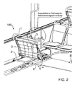
- FIG. 2 shows the obstruction device 3 in an extended position of use.
- the barrier device 3 can be extended to different heights and thus provide multiple use positions available, for. B. depending on the wheelchair width.
- FIG. 12 shows a perspective view of the barrier construction 100 of FIGS. 1 to 3 , with a wheelchair R located in a wheelchair space.
- the barrier structure 3 extends in sections coaxially with the upper part 1 (namely in the transverse direction Q of the vehicle or the barrier construction 100) and in sections coaxially with it the lower part 2 (namely, in the transverse direction Q of the vehicle or the Abhalteungskonstrutation 100) and additionally in sections in two other spatial directions (namely in the vertical direction H and longitudinal direction L of the vehicle or the Ableungskonstrutement 100).
- the blocking device 3 can extend into virtually all three spatial directions Q, H, L.
- the barrier structure 100 does not have undesirable parts projecting from the upper part 1 and the lower part 2, which on the one hand reduces the risk of injury, especially of standing vehicle occupants, and on the other hand creates a visually appealing barrier construction 100. Since the barrier means 3 requires no space on the outside of the upper part 1 and the lower part 2, the latter can be used for other purposes, for example, for attachment of attachments of the vehicle interior, z. B. folding seat, upholstered plate, etc ..
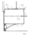
- FIG. 4 shows a front view of the barrier construction 100 of FIGS. 1 to 3
- FIG. 5 shows a perspective detail view of the detail A from FIG. 4 ,
- FIG. 5 shows an access 10, via which the shaft 6 described below can be actuated axially.
- the access 10 for actuating the shaft 6 is formed in a curved portion of the obstruction device 3.
- the shaft 6 is equipped with a coupling device 11 for actuation by means of an external or internal square key 12.
- the coupling device 11 is arranged at an axial end portion of the shaft 6.
- FIG. 6 shows a longitudinal section of a part of the Abhalteungskonstrutation 100 of FIGS. 1 to 5
- the aforementioned rotatable shaft 6 to see, which extends in sections coaxially in the upper part 1 and partially coaxially in the obstruction device 3.
- the shaft 6 is rotatable via the access 10 by means of the key 12 to actuate a fixing 9 for fixing the obstruction device 3 in the retracted position and in an extended position relative to the upper part 1.
- the obstruction device 3 can be fixed in the retracted position via the fixation device 9 which can be actuated by means of the shaft 6 in order to prevent unauthorized removal of the barrier construction 3.
- the driver of the bus can release the fixation 9, which can be actuated via the shaft 6, and bring the obstruction device 3 into an extended position.
- the barrier device 3 can then be extended via the actuatable means of the shaft 6 fixing 9 in the Fixed position to prevent accidental displacement of the barrier device 3.
- FIG. 7 shows a longitudinal section of the detail B from FIG. 6
- FIG. 7 shows in particular how the fixation 9 can be executed.
- the fixation 9 is formed within the upper part 1 so that it is not visible from the outside.
- the fixation 9 is formed by a plurality of elastic elements 9.1 and a plurality of cam parts 9.2 spaced from one another in the direction of displacement V of the obstruction device 3.
- the cam parts 9.2 are pressed by rotation radially against the elastic elements 9.1 in order to clamp them against the upper part 1.
- the cam parts 9.2 are formed by the cross-sectional shape of the shaft 6, which is designed in the embodiment shown as a square profile.
- FIG. 8 shows a cross section along line BB FIG. 6 ,
- the cam parts 9.2 press against the elastic elements 9.1, which results in that the elastic elements 9.1 are pressed against the upper part 1.
- the barrier device 3 can be fixed.
- FIG. 8 As can be seen, when the shaft 6 is rotated by 45 °, the loading of the cam parts 9.2 on the elastic elements 9.1 is released, resulting in that the obstruction device 3 can be moved.
- FIG. 9 shows a cross section along line CC FIG. 6
- FIG. 9 shows that the adjustment of the rotational movement of the shaft 6 by a cam-link construction 7, 8 (cam 7, link 8) is limited.
- the cam 7 is rotatably formed on the shaft 6, while the slide 8 is formed non-rotatable to serve as an abutment or attachment for the cam 7.
- FIG. 10 shows a longitudinal section along line DD FIG. 6
- FIG. 10 shows a slot 4 with an adjustment X, along which the barrier device 3 is displaceable.
- a stop 5 (for example a grub screw) protrudes into the oblong hole 4 in order to limit the translational displacement of the obstruction device 3 in the retracted position and the maximally extended position.
- FIG. 11 shows a longitudinal section of a portion of a barrier construction 100 according to another embodiment of the invention.
- FIG. 11 shows, in particular, an alternative possibility for forming the fixation 9 FIG. 11
- the fixing 9 is formed by two wedges 9.3 and 9.4.
- One of the wedges 9.3, 9.4 is by means of one with the shaft 6 rotatably connected threaded pin 9.5 against the other of the wedges 9.3, 9.4 slidably to produce a tension with the upper part 1.
- FIG. 12 shows a longitudinal section of a barrier construction 100 according to yet another embodiment of the invention.
- FIG. 12 shows in particular another possibility for forming the fixation 9.
- the fixing 9 is formed via an elastic element 9.6 and two abutment parts 9.7.
- the elastic element 9.6 is arranged between the two abutment parts 9.7.
- An abutment part 9.7 is by means of a non-rotatably connected to the shaft 6 threaded pin 9.8 axially against the elastic element 9.6 pressed to clamp it radially against the upper part 1.
- the elastic element 9.6 is also fixed by at least one of the abutment parts 9.7 so that it is prevented from co-rotating.
- the abutment part 9.7 comprises pins which engage positively in the elastic element 9.6.
- the shaft 6 and the fixing 9 and the associated features are formed on the upper part 1.
- the shaft 6 and the fixation 9 and the associated features can also be formed on the lower part 2.
Landscapes
- Engineering & Computer Science (AREA)
- Public Health (AREA)
- Health & Medical Sciences (AREA)
- Transportation (AREA)
- Mechanical Engineering (AREA)
- Aviation & Aerospace Engineering (AREA)
- Animal Behavior & Ethology (AREA)
- Life Sciences & Earth Sciences (AREA)
- General Health & Medical Sciences (AREA)
- Veterinary Medicine (AREA)
- Chemical & Material Sciences (AREA)
- Combustion & Propulsion (AREA)
- Refuge Islands, Traffic Blockers, Or Guard Fence (AREA)
- Seats For Vehicles (AREA)
- Vehicle Step Arrangements And Article Storage (AREA)
- Housing For Livestock And Birds (AREA)
- Handcart (AREA)
- Body Structure For Vehicles (AREA)
Abstract
Description
- Die Erfindung betrifft eine Abschrankungskonstruktion für einen Rollstuhlplatz in einem Fahrzeug, vorzugsweise in einem Omnibus.
-
Figur 13 zeigt eine perspektivische Ansicht einer Abschrankungskonstruktion A für einen Rollstuhlplatz in einem Omnibus gemäß Stand der Technik. Die Abschrankungskonstruktion A umfasst eine schwenk- oder klappbare Abschrankungseinrichtung B. Die Abschrankungseinrichtung B kann zwischen einer hochgeklappten Nicht-Gebrauchsstellung und einer ausgeklappten Gebrauchsstellung verschwenkt werden, was durch den Doppelpfeil inFigur 13 schematisch angedeutet ist. Nachteilig an der inFigur 13 gezeigten Abschrankungskonstruktion A ist, dass der erforderliche Schwenk- oder Klappmechanismus konstruktiv relativ aufwändig ist. Zudem umfasst die Abschrankungskonstruktion A eine Vielzahl abstehender Teile, was die Verletzungs- oder Unfallgefahr erhöht und zudem zu einem optisch wenig ansprechenden Erscheinungsbild führt. - Eine Aufgabe der Erfindung ist es, eine verbesserte und/oder alternative Abschrankungskonstruktion für einen Rollstuhlplatz eines Fahrzeugs, insbesondere eines Omnibusses, zu schaffen.
- Diese Aufgabe kann mit den Merkmalen des unabhängigen Anspruchs gelöst werden. Vorteilhafte Weiterbildungen können den Unteransprüchen und der folgenden Beschreibung entnommen werden.
- Die Erfindung schafft eine Abschrankungskonstruktion für einen Rollstuhlplatz in einem Fahrzeug, vorzugsweise in einem Omnibus. Die Abschrankungskonstruktion umfasst ein Oberteil und ein Unterteil zur zweckmäßig feststehenden, mittelbaren oder unmittelbaren Montage an das Fahrzeug und eine Abschrankungseinrichtung, die mit dem Oberteil und dem Unterteil verbunden ist. Die Abschrankungseinrichtung zeichnet sich insbesondere dadurch aus, dass sie relativ zu dem Oberteil und dem Unterteil translatorisch in eine eingefahrene Stellung (Nicht-Gebrauchsstellung) und eine oder mehrere ausgefahrene Stellungen (Gebrauchsstellung(en)) verschiebbar ist. Die Abschrankungseinrichtung ist zweckmäßig in Fahrzeugquerrichtung verschiebbar.
- Es ist möglich, dass die Abschrankungseinrichtung stufenlos verschiebbar ist.
- Die Abschrankungseinrichtung ist vorzugsweise entlang eines Langlochs verschiebbar. In das Langloch kann ein Anschlag (z. B. eine Madenschraube) hineinragen, um den translatorischen Verstellweg der Abschrankungseinrichtung in der eingefahrenen Stellung und der maximal ausgefahrenen Stellung zu begrenzen. Das Langloch definiert somit zweckmäßig den Verstellweg der Abschrankungseinrichtung.
- Es ist möglich, dass die Abschrankungskonstruktion eine drehbare Welle aufweist. Die Welle ist vorzugsweise drehbar, um eine Fixierung zum Fixieren der Abschrankungseinrichtung in der eingefahrenen Stellung und in einer ausgefahrenen Stellung relativ zu dem Oberteil oder dem Unterteil zu betätigen, z.B. zu aktivieren oder zu deaktivieren.
- Die Welle kann zumindest abschnittsweise koaxial innerhalb des Oberteils oder des Unterteils verlaufen. Alternativ oder ergänzend kann die Welle zumindest abschnittsweise koaxial innerhalb der Abschrankungseinrichtung verlaufen.
- Die Fixierung kann z.B. als Verspannfixierung (z.B. Reibungs- oder Klemmfixierung) ausgeführt sein.
- Die Fixierung kann innerhalb des Oberteils oder des Unterteils angeordnet sein, vorzugsweise ohne von außen sichtbar zu sein.
- Der Verstellweg der Drehbewegung der Welle wird vorzugsweise durch eine Nocken-Kulissen-Konstruktion begrenzt. Der Nocken kann z.B. an der Welle ausgebildet sein. Die Kulisse ist vorzugsweise nicht-drehbar innerhalb des Oberteils oder des Unterteils angeordnet, z.B. an einem drehfest mit dem Oberteil ausgebildeten Halteteil. Der Verstellweg der Drehbewegung der Welle ist vorzugsweise auf ungefähr 45° begrenzt.
- Die Fixierung kann durch zumindest ein elastisches Element (z. B. ein Gummielement) und zumindest ein Nockenteil gebildet werden. Das Nockenteil kann zweckmäßig durch seine Drehung radial gegen das elastische Element gedrückt werden, um es gegen das Oberteil oder das Unterteil zu verspannen. Das Nockenteil kann an der Welle ausgebildet sein und/oder quasi durch die Querschnittsform der Welle selbst gebildet werden. Hierzu kann die Welle z.B. eine zumindest dreikantige, vorzugsweise zumindest vierkantige Welle sein.
- Das elastische Element ist vorzugsweise in einer Öffnung oder Aussparung der Abschrankungseinrichtung fixiert, insbesondere um ein ungewolltes Mitdrehen zu verhindern. Vorzugsweise sind mehrere elastische Elemente längs der Abschrankungseinrichtung beabstandet voneinander angeordnet.
- Vorzugsweise sind mehrere Nockenteile in Umfangsrichtung der Welle voneinander beabstandet.
- Es ist möglich, dass die Fixierung mittels zumindest zweier Keile gebildet wird. Ein Keil kann vorzugsweise mittels eines mit der Welle drehfest verbundenen Gewindestifts gegen den anderen Teil verschoben werden, um eine Verspannung mit dem Oberteil oder dem Unterteil zu erzeugen.
- Es ist ferner möglich, dass die Fixierung mittels eines elastischen Elements (z. B. ein Gummielement) und zweier Widerlagerteile gebildet wird. Das elastische Element ist zweckmäßig zwischen den zwei Widerlagerteilen angeordnet. Ein Widerlagerteil kann vorzugsweise mittels eines drehfest mit der Welle verbundenen Gewindestifts axial gegen das elastische Element gedrückt werden, um es radial gegen das Oberteil oder das Unterteil zu verspannen.
- Das elastische Element wird vorzugsweise durch eines der Widerlagerteile fixiert, um es so an einem Mitdrehen zu hindern.
- Die Abschrankungseinrichtung kann abschnittsweise in dem Oberteil und/oder dem Unterteil verlaufen, vorzugsweise koaxial.
- Es ist möglich, dass das Oberteil, das Unterteil und/oder die Abschrankungseinrichtung als Rohrkonstruktion ausgeführt ist.
- Die Abschrankungseinrichtung umfasst einen Zugang (z. B. eine Aussparung oder Öffnung), über den die Welle mittels einer Kopplungseinrichtung vorzugsweise axial betätigbar ist.
- Der Zugang zur Betätigung der Welle ist vorzugsweise in einem Krümmungsabschnitt der Abschrankungseinrichtung ausgebildet.
- Die Kopplungseinrichtung ist vorzugsweise an einem axialen Endabschnitt der Welle angeordnet und zur Betätigung mittels eines Innen- oder Außenvierkantschlüssels ausgebildet.
- Es ist möglich, dass die Abschrankungseinrichtung sich abschnittsweise koaxial zu dem Oberteil und/ oder dem Unterteil erstreckt und zusätzlich dazu abschnittsweise in zwei weiteren Raumrichtungen, sodass sich die Abschrankungseinrichtung über quasi alle drei Raumrichtungen (Längs-, Quer- und Höhenrichtung) erstreckt.
- Die Erfindung ist nicht auf eine Abschrankungskonstruktion beschränkt, sondern umfasst auch ein Fahrzeug, vorzugsweise einen Omnibus, mit einem Rollstuhlplatz und einer Abschrankungskonstruktion, wie hierin beschrieben.
- Die zuvor beschriebenen bevorzugten Ausführungsformen und Merkmale der Erfindung sind beliebig miteinander kombinierbar. Andere vorteilhafte Weiterbildungen der Erfindung sind in den Unteransprüchen offenbart oder ergeben sich aus der folgenden Beschreibung bevorzugter Ausführungsformen der Erfindung in Verbindung mit den beigefügten Figuren.
- Figur 1
- zeigt eine perspektivische Ansicht einer Abschrankungskonstruktion für einen Rollstuhlplatz gemäß einer Ausführungsform der Erfindung mit einer Abschrankungseinrichtung in einer eingefahrenen Stellung,
- Figur 2
- zeigt eine perspektivische Ansicht der Abschrankungskonstruktion aus
Figur 1 mit der Abschrankungseinrichtung in einer ausgefahrenen Stellung, - Figur 3
- zeigt eine perspektivische Ansicht der Abschrankungskonstruktion der
Figur 2 mit einem in einem Rollstuhlplatz angeordneten Rollstuhl, - Figur 4
- zeigt eine Vorderansicht der Abschrankungskonstruktion der
Figuren 1-3 , - Figur 5
- zeigt eine perspektivische Detailansicht eines Teil der Abschrankungskonstruktion der
Figuren 1-4 , - Figur 6
- zeigt einen Längsschnitt eines Teils der Abschrankungskonstruktion der
Figuren 1-5 , - Figur 7
- zeigt einen Längsschnitt eines Teils der Abschrankungskonstruktion der
Figuren 1-6 , - Figur 8
- zeigt einen Querschnitt entlang der Linie B-B aus
Figur 6 , - Figur 9
- zeigt einen Querschnitt entlang der Linie C-C aus
Figur 6 , - Figur 10
- zeigt einen Längsschnitt entlang der Linie D-D aus
Figur 6 , - Figur 11
- zeigt einen Längsschnitt eines Teils einer Abschrankungskonstruktion gemäß einer anderen Ausführungsform der Erfindung,
- Figur 12
- zeigt einen Längsschnitt eines Teils einer Abschrankungskonstruktion gemäß einer wiederum anderen Ausführungsform der Erfindung, und
- Figur 13
- zeigt eine perspektivische Ansicht einer Abschrankungskonstruktion gemäß Stand der Technik.
- Die in den Figuren gezeigten Ausführungsformen stimmen teilweise überein, so dass für gleiche oder ähnliche Teile die gleichen Bezugszeichen verwendet sind und zu deren Erläuterung auch auf die Beschreibung der anderen Ausführungsformen verwiesen wird, um Wiederholungen zu vermeiden.
-
Figur 1 zeigt eine perspektivische Ansicht einer Abschrankungskonstruktion 100 für einen Rollstuhlplatz in einem Fahrzeug, vorzugsweise in einem Omnibus. Die Abschrankungskonstruktion 100 umfasst ein Oberteil 1 und ein Unterteil 2, die feststehend an das Fahrzeug montiert sind. Die Abschrankungskonstruktion 100 umfasst ferner eine mit dem Oberteil 1 und dem Unterteil 2 verbundene Abschrankungseinrichtung 3. Das Oberteil 1, das Unterteil 2 und die Abschrankungskonstruktion 3 sind als Rohrkonstruktion ausgeführt. - Die Abschrankungseinrichtung 3 ist relativ zu dem Oberteil 1 und dem Unterteil 3 translatorisch in eine eingefahrene Stellung und eine oder mehrere ausgefahrene Stellungen stufenlos in Fahrzeugquerrichtung Q (vgl.
Figur 3 ) verschiebbar, was durch die Doppelpfeile V schematisch angedeutet ist.Figur 1 zeigt die Abschrankungseinrichtung 3 in einer eingefahrenen Nicht-Gebrauchsstellung. Bezugszeichen 10 kennzeichnet einen Zugang, über den eine weiter unten beschriebene Welle 6 axial betätigt und dadurch gedreht werden kann. -
Figur 2 zeigt eine perspektivische Ansicht der Abschrankungskonstruktion 100 derFigur 1 .Figur 2 zeigt die Abschrankungseinrichtung 3 in einer ausgefahrenen Gebrauchsstellung. Die Abschrankungseinrichtung 3 kann unterschiedlich weit ausgefahren werden und somit mehrere Gebrauchstellungen zur Verfügung stellen, z. B. in Abhängigkeit der Rollstuhlbreite. -
Figur 3 zeigt eine perspektivische Ansicht der Abschrankungskonstruktion 100 derFiguren 1 bis 3 , mit einem in einem Rollstuhlplatz befindlichen Rollstuhl R. Die Abschrankungskonstruktion 3 erstreckt sich abschnittsweise koaxial zu dem Oberteil 1 (nämlich in Querrichtung Q des Fahrzeugs bzw. der Abschrankungskonstruktion 100) und abschnittsweise koaxial zu dem Unterteil 2 (nämlich in Querrichtung Q des Fahrzeugs bzw. der Abschrankungskonstruktion 100) und zusätzlich abschnittsweise in zwei weiteren Raumrichtungen (nämlich in Höhenrichtung H und Längsrichtung L des Fahrzeugs bzw. der Abschrankungskonstruktion 100). Die Abschrankungseinrichtung 3 kann sich dadurch in quasi alle drei Raumrichtungen Q, H, L erstrecken. - Aus den
Figuren 1 bis 3 wird ersichtlich, dass die Abschrankungskonstruktion 100 keine unerwünscht von dem Oberteil 1 und dem Unterteil 2 abstehende Teile aufweist, wodurch einerseits die Verletzungsgefahr vor allem stehender Fahrzeuginsassen reduziert wird und andererseits eine optisch ansprechende Abschrankungskonstruktion 100 geschaffen wird. Da die Abschrankungseinrichtung 3 keinen Bauraum an der Außenseite des Oberteils 1 und des Unterteils 2 erfordert, können letztgenannte für andere Zwecke genutzt werden, z.B. zur Anbringung von Anbauelementen der Fahrzeug-Innenausstattung, z. B. Klappsitz, Polsterplatte, etc.. -
Figur 4 zeigt eine Vorderansicht auf die Abschrankungskonstruktion 100 derFiguren 1 bis 3 .Figur 5 zeigt eine perspektivische Detailansicht des Details A ausFigur 4 . -
Figur 5 zeigt einen Zugang 10, über den die weiter unten beschriebene Welle 6 axial betätigt werden kann. Der Zugang 10 zur Betätigung der Welle 6 ist in einem Krümmungsabschnitt der Abschrankungseinrichtung 3 ausgebildet. Die Welle 6 ist mit einer Kopplungseinrichtung 11 zur Betätigung mittels eines Außen- oder Innenvierkantschlüssels 12 ausgestattet. Die Kopplungseinrichtung 11 ist an einem axialen Endabschnitt der Welle 6 angeordnet. -
Figur 6 zeigt einen Längsschnitt eines Teils der Abschrankungskonstruktion 100 derFiguren 1 bis 5 . InFigur 6 ist die zuvor erwähnte drehbare Welle 6 zu sehen, die sich abschnittsweise koaxial in dem Oberteil 1 und abschnittsweise koaxial in der Abschrankungseinrichtung 3 erstreckt. Die Welle 6 ist über den Zugang 10 mittels des Schlüssels 12 drehbar, um eine Fixierung 9 zum Fixieren der Abschrankungseinrichtung 3 in der eingefahrenen Stellung und in einer ausgefahrenen Stellung relativ zu dem Oberteil 1 zu betätigen. So kann die Abschrankungseinrichtung 3 über die mittels der Welle 6 betätigbare Fixierung 9 in der eingefahrenen Stellung fixiert werden, um ein unerlaubtes Herausziehen der Abschrankungskonstruktion 3 zu verhindern. Kommt jedoch ein Rollstuhlfahrer in den Omnibus, so kann der Fahrer des Omnibusses die über die Welle 6 betätigbare Fixierung 9 lösen und die Abschrankungseinrichtung 3 in eine ausgefahrene Stellung bringen. Die Abschrankungseinrichtung 3 kann daraufhin über die mittels der Welle 6 betätigbare Fixierung 9 in der ausgefahrenen Stellung fixiert werden, um ein ungewolltes Verschieben der Abschrankungseinrichtung 3 zu verhindern. -
Figur 7 zeigt einen Längsschnitt des Details B ausFigur 6 .Figur 7 zeigt insbesondere wie die Fixierung 9 ausgeführt sein kann. Die Fixierung 9 ist innerhalb des Oberteils 1 so ausgebildet, dass sie von außen nicht sichtbar ist. Die Fixierung 9 wird durch mehrere in Verschiebungsrichtung V der Abschrankungseinrichtung 3 voneinander beabstandeten elastischen Elementen 9.1 und mehrere Nockenteile 9.2 gebildet. Die Nockenteile 9.2 werden durch Drehung radial gegen die elastischen Elemente 9.1 gedrückt, um sie gegen das Oberteil 1 zu verspannen. Die Nockenteile 9.2 werden durch die Querschnittsform der Welle 6 gebildet, die in der gezeigten Ausführungsform als Vierkantprofil ausgeführt ist. -
Figur 8 zeigt einen Querschnitt entlang Linie B-B ausFigur 6 . Die Nockenteile 9.2 drücken gegen die elastischen Elemente 9.1, was dazu führt, dass die elastischen Elemente 9.1 gegen das Oberteil 1 gedrückt werden. Dadurch kann die Abschrankungseinrichtung 3 fixiert werden. AusFigur 8 wird ersichtlich, dass wenn die Welle 6 um 45° gedreht wird, die Beaufschlagung der Nockenteile 9.2 auf die elastischen Elemente 9.1 gelöst wird, was dazu führt, dass die Abschrankungseinrichtung 3 verschoben werden kann. -
Figur 9 zeigt einen Querschnitt entlang Linie C-C ausFigur 6 .Figur 9 zeigt, dass der Verstellweg der Drehbewegung der Welle 6 durch eine Nocken-Kulisse-Konstruktion 7, 8 (Nokken 7, Kulisse 8) begrenzt wird. Der Nocken 7 ist drehfest an der Welle 6 ausgebildet, während die Kulisse 8 nicht-drehbar ausgebildet ist, um als Widerlager oder Anlage für den Nokken 7 zu dienen. -
Figur 10 zeigt einen Längsschnitt entlang Linie D-D ausFigur 6 .Figur 10 zeigt ein Langloch 4 mit einem Verstellweg X, entlang dem die Abschrankungseinrichtung 3 verschiebbar ist. In das Langloch 4 ragt ein Anschlag 5 (z. B. eine Madenschraube), um den translatorischen Verstellweg der Abschrankungseinrichtung 3 in der eingefahrenen Stellung und der maximal ausgefahrenen Stellung zu begrenzen. -
Figur 11 zeigt einen Längsschnitt eines Teils einer Abschrankungskonstruktion 100 gemäß einer anderen Ausführungsform der Erfindung.Figur 11 zeigt insbesondere eine alternative Möglichkeit zur Ausbildung der Fixierung 9. Bei der inFigur 11 gezeigten Ausführungsform wird die Fixierung 9 über zwei Keile 9.3 und 9.4 gebildet. Einer der Keile 9.3, 9.4 ist mittels eines mit der Welle 6 drehfest verbundenen Gewindestifts 9.5 gegen den anderen der Keile 9.3, 9.4 verschiebbar, um eine Verspannung mit dem Oberteil 1 zu erzeugen. -
Figur 12 zeigt einen Längsschnitt einer Abschrankungskonstruktion 100 gemäß einer wiederum anderen Ausführungsform der Erfindung.Figur 12 zeigt insbesondere eine andere Möglichkeit zur Ausbildung der Fixierung 9. Bei der inFigur 12 gezeigten Ausführungsform wird die Fixierung 9 über ein elastisches Element 9.6 und zwei Widerlagerteile 9.7 gebildet. Das elastische Element 9.6 ist zwischen den zwei Widerlagerteilen 9.7 angeordnet. Ein Widerlagerteil 9.7 ist mittels eines drehfest mit der Welle 6 verbundenen Gewindestifts 9.8 axial gegen das elastische Element 9.6 drückbar, um es radial gegen das Oberteil 1 zu verspannen. Das elastische Element 9.6 wird zudem durch zumindest eines der Widerlagerteile 9.7 so fixiert, dass es an einem Mitdrehen gehindert wird. Dazu umfasst das Widerlagerteil 9.7 Zapfen, die formschlüssig in das elastische Element 9.6 eingreifen. - In den zuvor beschriebenen Ausführungsformen sind die Welle 6 und die Fixierung 9 und die damit einhergehenden Merkmale an dem Oberteil 1 ausgebildet. Alternativ oder ergänzend können die Welle 6 und die Fixierung 9 und die damit einhergehenden Merkmale ebenso an dem Unterteil 2 ausgebildet werden.
- Die Erfindung ist nicht auf die oben beschriebenen bevorzugten Ausführungsformen beschränkt. Vielmehr ist eine Vielzahl von Varianten und Abwandlungen möglich, die ebenfalls von dem Erfindungsgedanken Gebrauch machen und deshalb in den Schutzbereich fallen. Darüber hinaus beansprucht die Erfindung auch Schutz für den Gegenstand und die Merkmale der Unteransprüche, unabhängig von den in Bezug genommenen Merkmalen und Ansprüchen.
-
- 1
- Oberteil
- 2
- Unterteil
- 3
- Abschrankungseinrichtung
- 4
- Langloch
- 5
- Anschlag
- 6
- drehbare Welle
- 7
- Nocken
- 8
- Kulisse
- 9
- Fixierung
- 9.1
- zumindest ein elastisches Element
- 9.2
- zumindest ein Nockenteil
- 9.3
- Keil
- 9.4
- Keil
- 9.5
- Gewindestift
- 9.6
- elastisches Element
- 9.7
- Widerlagerteil(e)
- 9.8
- Gewindestift
- 10
- Zugang
- 11
- Kopplungseinrichtung
- 12
- Vierkantschlüssel
- 100
- Abschrankungskonstruktion
- R
- Rollstuhl
- V
- Verschieberichtung der Abschrankungseinrichtung
- X
- Verstellweg
- H
- Höhenrichtung
- Q
- Querrichtung
- L
- Längsrichtung
Claims (23)
- Abschrankungskonstruktion (100) für einen Rollstuhlplatz in einem Fahrzeug, vorzugsweise in einem Omnibus, mit einem Oberteil (1) und einem Unterteil (2) zur Montage an das Fahrzeug und einer mit dem Oberteil (1) und dem Unterteil (2) verbundenen Abschrankungseinrichtung (3), dadurch gekennzeichnet, dass die Abschrankungseinrichtung (3) relativ zu dem Oberteil (1) und dem Unterteil (2) translatorisch in eine eingefahrene Stellung und eine oder mehrere ausgefahrene Stellungen verschiebbar ist.
- Abschrankungskonstruktion (100) nach Anspruch 1, dadurch gekennzeichnet, dass die Abschrankungseinrichtung (3) stufenlos verschiebbar ist.
- Abschrankungskonstruktion (100) nach Anspruch 1 oder 2, dadurch gekennzeichnet, dass die Abschrankungseinrichtung (3) entlang eines Langlochs (4) verschiebbar ist und in das Langloch (4) ein Anschlag (5) hineinragt, um den translatorischen Verstellweg der Abschrankungseinrichtung (3) in der eingefahrenen Stellung und der maximal ausgefahrenen Stellung zu begrenzen.
- Abschrankungskonstruktion (100) nach einem der vorhergehenden Ansprüche, dadurch gekennzeichnet, dass die Abschrankungskonstruktion (100) eine drehbare Welle (6) aufweist, die drehbar ist, um eine Fixierung (9) zum Fixieren der Abschrankungseinrichtung (3) relativ zu dem Oberteil (1) oder dem Unterteil (2) zu betätigen.
- Abschrankungskonstruktion (100) nach Anspruch 4, dadurch gekennzeichnet, dass- die Welle (6) zumindest abschnittsweise koaxial innerhalb des Oberteils (1) oder des Unterteils (2) verläuft, und/oder- die Welle (6) zumindest abschnittsweise koaxial innerhalb der Abschrankungseinrichtung (3) verläuft.
- Abschrankungskonstruktion (100) nach Anspruch 4 oder 5, dadurch gekennzeichnet, dass die Fixierung (9) eine Verspannfixierung ist, insbesondere eine-Reibungs- oder Klemmfixierung.
- Abschrankungskonstruktion (100) nach einem der Ansprüche 4 bis 6, dadurch gekennzeichnet, dass die Fixierung (9) innerhalb des Oberteils (1) oder des Unterteils (2) ausgebildet ist, zweckmäßig ohne von außen sichtbar zu sein.
- Abschrankungskonstruktion (100) nach einem der Ansprüche 4 bis 7, dadurch gekennzeichnet, dass der Verstellweg der Drehbewegung der Welle (6) durch eine Nocken-Kulissen-Konstruktion (7, 8) begrenzt wird.
- Abschrankungskonstruktion (100) nach Anspruch 8, dadurch gekennzeichnet, dass der Nocken (7) an der Welle (6) ausgebildet ist und die Kulisse (8) relativ zu dem Oberteil (1) oder dem Unterteil (2) nicht-drehbar ausgebildet ist.
- Abschrankungskonstruktion (100) nach einem der Ansprüche 4 bis 9, dadurch gekennzeichnet, dass die Fixierung (9) durch zumindest ein elastisches Element (9.1) und zumindest ein Nockenteil (9.2) gebildet wird, wobei das Nockenteil (9.2) durch seine Drehung radial gegen das elastische Element (9.1) drückbar ist, um es gegen das Oberteil (1) oder das Unterteil (2) zu verspannen.
- Abschrankungskonstruktion (100) nach Anspruch 10, dadurch gekennzeichnet, dass das Nockenteil (9.2) an der Welle (6) ausgebildet ist und/oder durch die Querschnittsform der Welle (6) gebildet wird.
- Abschankungskonstruktion (100) nach Anspruch 10 oder 11, dadurch gekennzeichnet, dass das elastische Element (9.1) in einer Öffnung oder Aussparung der Abschrankungseinrichtung (3) fixiert angeordnet ist.
- Abschrankungskonstruktion (100) nach einem der Ansprüche 10 bis 12, dadurch gekennzeichnet, dass mehrere elastische Elemente (9.1) längs der Abschrankungseinrichtung (3) beabstandet voneinander angeordnet sind.
- Abschrankungskonstruktion (100) nach einem der Ansprüche 10 bis 13, dadurch gekennzeichnet, dass mehrere Nockenteile (9.2) in Umfangsrichtung der Welle (6) beabstandet voneinander angeordnet sind.
- Abschrankungskonstruktion (100) nach einem der Ansprüche 4 bis 9, dadurch gekennzeichnet, dass die Fixierung (9) über zumindest zwei Keile (9.3, 9.4) gebildet wird, wobei ein Keil, vorzugsweise mittels eines mit der Welle (6) drehfest verbundenen Gewindestifts (9.5), gegen den anderen Keil verschiebbar ist, um eine Verspannung mit dem Oberteil (1) oder dem Unterteil (2) zu erzeugen.
- Abschrankungskonstruktion (100) nach einem der Ansprüche 4 bis 9, dadurch gekennzeichnet, dass die Fixierung (9) über ein elastisches Element (9.6) und zwei Widerlagerteile (9.7) gebildet wird, wobei das elastische Element (9.6) zwischen den zwei Widerlagerteilen (9.7) angeordnet ist und ein Widerlagerteil (9.7), vorzugsweise mittels eines drehfest mit der Welle (6) verbundenen Gewindestifts (9.8), axial gegen das elastische Element (9.6) drückbar ist, um es radial gegen das Oberteil (1) oder das Unterteil (2) zu verspannen.
- Abschrankungskonstruktion (100) nach Anspruch 16, dadurch gekennzeichnet, dass das elastische Element (9.6) durch ein Widerlagerteile (9.7) fixiert ist, um es an einem Mitdrehen zu hindern.
- Abschrankungskonstruktion (100) nach einem der vorhergehenden Ansprüche, dadurch gekennzeichnet, dass die Abschrankungseinrichtung (3) abschnittsweise in dem Oberteil (1) und/oder dem Unterteil (2) verläuft, vorzugsweise koaxial.
- Abschrankungskonstruktion (100) nach einem der vorhergehenden Ansprüche, dadurch gekennzeichnet, dass das Oberteil (1), das Unterteil (2) und die Abschrankungseinrichtung (3) als Rohrkonstruktion ausgeführt sind.
- Abschrankungskonstruktion (100) nach einem der Ansprüche 4 bis 19, dadurch gekennzeichnet, dass die Welle (6) über einen Zugang (10) und eine Kopplungseinrichtung (11) axial betätigbar ist und/oder der Zugang (10) zur Betätigung der Welle (6) in einem Krümmungsabschnitt der Abschrankungseinrichtung (3) ausgebildet ist.
- Abschrankungskonstruktion (100) nach einem der Ansprüche 4 bis 20, dadurch gekennzeichnet, dass die Welle (6) eine Kopplungseinrichtung (11) aufweist, die an einem axialen Endabschnitt der Welle (6) angeordnet ist und zur Betätigung mittels eines Schlüssels (12) ausgeführt ist.
- Abschrankungskonstruktion (100) nach einem der vorhergehenden Ansprüche, dadurch gekennzeichnet, dass die Abschrankungseinrichtung (3) sich abschnittsweise koaxial zu dem Oberteil (1) und/ oder dem Unterteil (2) erstreckt und zusätzlich dazu abschnittsweise in zwei weiteren Raumrichtungen (H, L).
- Fahrzeug, vorzugsweise Omnibus, mit einem Rollstuhlplatz und einer Abschrankungskonstruktion (100) nach einem der vorhergehenden Ansprüche.
Applications Claiming Priority (1)
| Application Number | Priority Date | Filing Date | Title |
|---|---|---|---|
| DE102013016746.9A DE102013016746A1 (de) | 2013-10-09 | 2013-10-09 | Abschrankungskonstruktion für einen Rollstuhlplatz in einem Fahrzeug |
Publications (2)
| Publication Number | Publication Date |
|---|---|
| EP2859871A1 true EP2859871A1 (de) | 2015-04-15 |
| EP2859871B1 EP2859871B1 (de) | 2016-04-06 |
Family
ID=51266072
Family Applications (1)
| Application Number | Title | Priority Date | Filing Date |
|---|---|---|---|
| EP14002693.1A Active EP2859871B1 (de) | 2013-10-09 | 2014-08-01 | Abschrankungskonstruktion für einen Rollstuhlplatz in einem Fahrzeug |
Country Status (7)
| Country | Link |
|---|---|
| EP (1) | EP2859871B1 (de) |
| CN (1) | CN104554050B (de) |
| BR (1) | BR102014020418B1 (de) |
| DE (1) | DE102013016746A1 (de) |
| HU (1) | HUE029699T2 (de) |
| PL (1) | PL2859871T3 (de) |
| RU (1) | RU2662585C2 (de) |
Cited By (2)
| Publication number | Priority date | Publication date | Assignee | Title |
|---|---|---|---|---|
| CN109017597A (zh) * | 2018-08-06 | 2018-12-18 | 倪晋挺 | 公交车轮椅限位装置 |
| JP2025516849A (ja) * | 2022-05-30 | 2025-05-30 | ビーワイディー カンパニー リミテッド | 車両グラブ・レール組立体および車両 |
Families Citing this family (4)
| Publication number | Priority date | Publication date | Assignee | Title |
|---|---|---|---|---|
| FR3063429A1 (fr) * | 2017-03-06 | 2018-09-07 | Newtl | Amenagement pour emplacement d'usager en fauteuil roulant |
| CN108609188A (zh) * | 2018-03-26 | 2018-10-02 | 高博通信(上海)有限公司 | 一种多功能经济舱座椅 |
| CN108715143B (zh) * | 2018-05-28 | 2020-05-05 | 范瑶飞 | 一种用于公共交通工具的约束设备 |
| CN109760558B (zh) * | 2018-12-28 | 2020-08-25 | 南京溧水高新创业投资管理有限公司 | 一种多功能新能源公交汽车调节座椅 |
Citations (4)
| Publication number | Priority date | Publication date | Assignee | Title |
|---|---|---|---|---|
| GB2063956A (en) * | 1979-11-21 | 1981-06-10 | Tubular Barriers Ltd | Barriers and like guards |
| DE102009004525A1 (de) * | 2009-01-09 | 2010-08-05 | Bombardier Transportation Gmbh | Fangvorrichtung für einen Rollstuhl in einem Fahrzeug, insbesondere Schienenfahrzeug |
| WO2013045732A1 (es) * | 2011-09-27 | 2013-04-04 | Universidad Politécnica De Valencia | Sistema de seguridad pasivo para carritos de niños en vehículos de transporte público |
| DE102012023157A1 (de) * | 2012-11-28 | 2014-05-28 | Daimler Ag | Sicherungsvorrichtung und Verkehrsmittel mit einer Sicherungsvorrichtung |
Family Cites Families (7)
| Publication number | Priority date | Publication date | Assignee | Title |
|---|---|---|---|---|
| DE1256957B (de) * | 1965-05-31 | 1967-12-21 | Siegfried Schiansky | Klemmsperre bei Teleskoprohrverbindungen, insbesondere fuer ausziehbare Stativbeine,fuer Foto- und Kinostative oder auch fuer Projektionstische |
| GB2241995A (en) * | 1990-03-17 | 1991-09-18 | Colin Joseph Harwood | Round tube locking device under compression |
| GB2424856B (en) * | 2005-04-07 | 2008-05-14 | Alexander Dennis Ltd | A passenger bus |
| NO328997B1 (no) * | 2008-05-06 | 2010-07-12 | Hag As | Justeringanordning for stolarmlene |
| RU82668U1 (ru) * | 2008-09-12 | 2009-05-10 | Производственное республиканское унитарное предприятие "Минский автомобильный завод" (РУП "МАЗ") | Автобус городской |
| CN202368426U (zh) * | 2011-12-15 | 2012-08-08 | 安徽安凯汽车股份有限公司 | 可活动的安全扶手 |
| CN202806483U (zh) * | 2012-09-27 | 2013-03-20 | 厦门金龙联合汽车工业有限公司 | 一种可旋转收回的公交扶手 |
-
2013
- 2013-10-09 DE DE102013016746.9A patent/DE102013016746A1/de not_active Withdrawn
-
2014
- 2014-08-01 PL PL14002693.1T patent/PL2859871T3/pl unknown
- 2014-08-01 HU HUE14002693A patent/HUE029699T2/hu unknown
- 2014-08-01 EP EP14002693.1A patent/EP2859871B1/de active Active
- 2014-08-19 BR BR102014020418A patent/BR102014020418B1/pt active IP Right Grant
- 2014-09-24 RU RU2014138633A patent/RU2662585C2/ru active
- 2014-10-09 CN CN201410526926.4A patent/CN104554050B/zh active Active
Patent Citations (4)
| Publication number | Priority date | Publication date | Assignee | Title |
|---|---|---|---|---|
| GB2063956A (en) * | 1979-11-21 | 1981-06-10 | Tubular Barriers Ltd | Barriers and like guards |
| DE102009004525A1 (de) * | 2009-01-09 | 2010-08-05 | Bombardier Transportation Gmbh | Fangvorrichtung für einen Rollstuhl in einem Fahrzeug, insbesondere Schienenfahrzeug |
| WO2013045732A1 (es) * | 2011-09-27 | 2013-04-04 | Universidad Politécnica De Valencia | Sistema de seguridad pasivo para carritos de niños en vehículos de transporte público |
| DE102012023157A1 (de) * | 2012-11-28 | 2014-05-28 | Daimler Ag | Sicherungsvorrichtung und Verkehrsmittel mit einer Sicherungsvorrichtung |
Cited By (3)
| Publication number | Priority date | Publication date | Assignee | Title |
|---|---|---|---|---|
| CN109017597A (zh) * | 2018-08-06 | 2018-12-18 | 倪晋挺 | 公交车轮椅限位装置 |
| JP2025516849A (ja) * | 2022-05-30 | 2025-05-30 | ビーワイディー カンパニー リミテッド | 車両グラブ・レール組立体および車両 |
| EP4516583A4 (de) * | 2022-05-30 | 2025-08-13 | Byd Co Ltd | Fahrzeuggreiferschienenanordnung und fahrzeug |
Also Published As
| Publication number | Publication date |
|---|---|
| CN104554050B (zh) | 2019-03-08 |
| BR102014020418B1 (pt) | 2021-08-24 |
| DE102013016746A1 (de) | 2015-04-09 |
| RU2662585C2 (ru) | 2018-07-26 |
| CN104554050A (zh) | 2015-04-29 |
| BR102014020418A2 (pt) | 2016-04-19 |
| EP2859871B1 (de) | 2016-04-06 |
| PL2859871T3 (pl) | 2016-09-30 |
| HUE029699T2 (hu) | 2017-03-28 |
| RU2014138633A (ru) | 2016-04-20 |
Similar Documents
| Publication | Publication Date | Title |
|---|---|---|
| EP2859871B1 (de) | Abschrankungskonstruktion für einen Rollstuhlplatz in einem Fahrzeug | |
| DE102009021211B4 (de) | Fahrzeugsitz | |
| DE102004017688B4 (de) | Kopfstütze für Automobilsitze | |
| EP3068963B1 (de) | Scharnier, insbesondere für ein möbelstück | |
| EP2070761B1 (de) | Getriebebaueinheit einer Verstelleinrichtung eines Kraftfahrzeugs | |
| DE102014210134B4 (de) | Armauflagevorrichtung für einen Fahrzeuginnenraum | |
| DE102016111974A1 (de) | Vorrichtung zum Öffnen und Schließen einer verschiebbaren Armlehnenkonsole | |
| DE19943573A1 (de) | Sitz für Kraftfahrzeug | |
| DE102015105618A1 (de) | Flugzeugsitzvorrichtung | |
| DE102019101523A1 (de) | Sektorarm und Rastklinkenbaugruppe | |
| DE10051668B4 (de) | Klappbarer Rücksitz für Fahrzeuge | |
| EP3330122B1 (de) | Vorrichtung für ein fahrzeugsitz mit einer dreheinheit und einer verschiebeeinheit | |
| EP2944436A2 (de) | Tragegestell mit klapperfrei verriegelbaren tragelementen | |
| DE102015121018B4 (de) | Längenverstellbare Samerstange | |
| DE102011053395A1 (de) | Mittelkonsolenanordnung | |
| DE102008062085A1 (de) | Vorrichtung zur Aufnahme eines Sitzes in einem Fahrzeug | |
| DE102006001029B3 (de) | Schutzvorrichtung für ein Kraftfahrzeug | |
| EP3158907A1 (de) | Klapp- und schwenkbarer stützklappgriff, insbesondere für den sanitärbereich | |
| EP3463239B1 (de) | Mobilitätshilfe | |
| EP2837527B1 (de) | Blockierbarer Klappsitz | |
| DE202017100536U1 (de) | Manuell längsverstellbarer Kraftfahrzeugsitz | |
| EP3893696B1 (de) | Sitzmöbel mit einer lordosenstützvorrichtung | |
| DE102008009295B4 (de) | Fahrzeugsitz mit einem Sitzteil und einer schwenkbar mit dem Sitzteil verbundenen, arretierbaren Rückenlehne und mit einer klappbaren arretierbaren Kopfstütze | |
| DE102021117292A1 (de) | Ladungssicherungspfosten | |
| DE102005011210B4 (de) | Fahrzeugsitz |
Legal Events
| Date | Code | Title | Description |
|---|---|---|---|
| PUAI | Public reference made under article 153(3) epc to a published international application that has entered the european phase |
Free format text: ORIGINAL CODE: 0009012 |
|
| 17P | Request for examination filed |
Effective date: 20150225 |
|
| AK | Designated contracting states |
Kind code of ref document: A1 Designated state(s): AL AT BE BG CH CY CZ DE DK EE ES FI FR GB GR HR HU IE IS IT LI LT LU LV MC MK MT NL NO PL PT RO RS SE SI SK SM TR |
|
| AX | Request for extension of the european patent |
Extension state: BA ME |
|
| RIC1 | Information provided on ipc code assigned before grant |
Ipc: A61G 3/08 20060101AFI20150923BHEP |
|
| GRAP | Despatch of communication of intention to grant a patent |
Free format text: ORIGINAL CODE: EPIDOSNIGR1 |
|
| INTG | Intention to grant announced |
Effective date: 20151103 |
|
| GRAS | Grant fee paid |
Free format text: ORIGINAL CODE: EPIDOSNIGR3 |
|
| GRAA | (expected) grant |
Free format text: ORIGINAL CODE: 0009210 |
|
| AK | Designated contracting states |
Kind code of ref document: B1 Designated state(s): AL AT BE BG CH CY CZ DE DK EE ES FI FR GB GR HR HU IE IS IT LI LT LU LV MC MK MT NL NO PL PT RO RS SE SI SK SM TR |
|
| REG | Reference to a national code |
Ref country code: GB Ref legal event code: FG4D Free format text: NOT ENGLISH |
|
| REG | Reference to a national code |
Ref country code: AT Ref legal event code: REF Ref document number: 786938 Country of ref document: AT Kind code of ref document: T Effective date: 20160415 Ref country code: CH Ref legal event code: EP |
|
| REG | Reference to a national code |
Ref country code: IE Ref legal event code: FG4D Free format text: LANGUAGE OF EP DOCUMENT: GERMAN |
|
| REG | Reference to a national code |
Ref country code: DE Ref legal event code: R096 Ref document number: 502014000545 Country of ref document: DE |
|
| REG | Reference to a national code |
Ref country code: SE Ref legal event code: TRGR |
|
| REG | Reference to a national code |
Ref country code: NL Ref legal event code: FP |
|
| REG | Reference to a national code |
Ref country code: LT Ref legal event code: MG4D |
|
| REG | Reference to a national code |
Ref country code: FR Ref legal event code: PLFP Year of fee payment: 3 |
|
| PG25 | Lapsed in a contracting state [announced via postgrant information from national office to epo] |
Ref country code: NO Free format text: LAPSE BECAUSE OF FAILURE TO SUBMIT A TRANSLATION OF THE DESCRIPTION OR TO PAY THE FEE WITHIN THE PRESCRIBED TIME-LIMIT Effective date: 20160706 Ref country code: LT Free format text: LAPSE BECAUSE OF FAILURE TO SUBMIT A TRANSLATION OF THE DESCRIPTION OR TO PAY THE FEE WITHIN THE PRESCRIBED TIME-LIMIT Effective date: 20160406 Ref country code: FI Free format text: LAPSE BECAUSE OF FAILURE TO SUBMIT A TRANSLATION OF THE DESCRIPTION OR TO PAY THE FEE WITHIN THE PRESCRIBED TIME-LIMIT Effective date: 20160406 Ref country code: IS Free format text: LAPSE BECAUSE OF FAILURE TO SUBMIT A TRANSLATION OF THE DESCRIPTION OR TO PAY THE FEE WITHIN THE PRESCRIBED TIME-LIMIT Effective date: 20160806 |
|
| PG25 | Lapsed in a contracting state [announced via postgrant information from national office to epo] |
Ref country code: GR Free format text: LAPSE BECAUSE OF FAILURE TO SUBMIT A TRANSLATION OF THE DESCRIPTION OR TO PAY THE FEE WITHIN THE PRESCRIBED TIME-LIMIT Effective date: 20160707 Ref country code: PT Free format text: LAPSE BECAUSE OF FAILURE TO SUBMIT A TRANSLATION OF THE DESCRIPTION OR TO PAY THE FEE WITHIN THE PRESCRIBED TIME-LIMIT Effective date: 20160808 Ref country code: ES Free format text: LAPSE BECAUSE OF FAILURE TO SUBMIT A TRANSLATION OF THE DESCRIPTION OR TO PAY THE FEE WITHIN THE PRESCRIBED TIME-LIMIT Effective date: 20160406 Ref country code: RS Free format text: LAPSE BECAUSE OF FAILURE TO SUBMIT A TRANSLATION OF THE DESCRIPTION OR TO PAY THE FEE WITHIN THE PRESCRIBED TIME-LIMIT Effective date: 20160406 Ref country code: LV Free format text: LAPSE BECAUSE OF FAILURE TO SUBMIT A TRANSLATION OF THE DESCRIPTION OR TO PAY THE FEE WITHIN THE PRESCRIBED TIME-LIMIT Effective date: 20160406 Ref country code: HR Free format text: LAPSE BECAUSE OF FAILURE TO SUBMIT A TRANSLATION OF THE DESCRIPTION OR TO PAY THE FEE WITHIN THE PRESCRIBED TIME-LIMIT Effective date: 20160406 |
|
| PG25 | Lapsed in a contracting state [announced via postgrant information from national office to epo] |
Ref country code: BE Free format text: LAPSE BECAUSE OF NON-PAYMENT OF DUE FEES Effective date: 20160831 |
|
| REG | Reference to a national code |
Ref country code: DE Ref legal event code: R097 Ref document number: 502014000545 Country of ref document: DE |
|
| PG25 | Lapsed in a contracting state [announced via postgrant information from national office to epo] |
Ref country code: RO Free format text: LAPSE BECAUSE OF FAILURE TO SUBMIT A TRANSLATION OF THE DESCRIPTION OR TO PAY THE FEE WITHIN THE PRESCRIBED TIME-LIMIT Effective date: 20160406 Ref country code: SK Free format text: LAPSE BECAUSE OF FAILURE TO SUBMIT A TRANSLATION OF THE DESCRIPTION OR TO PAY THE FEE WITHIN THE PRESCRIBED TIME-LIMIT Effective date: 20160406 Ref country code: EE Free format text: LAPSE BECAUSE OF FAILURE TO SUBMIT A TRANSLATION OF THE DESCRIPTION OR TO PAY THE FEE WITHIN THE PRESCRIBED TIME-LIMIT Effective date: 20160406 Ref country code: CZ Free format text: LAPSE BECAUSE OF FAILURE TO SUBMIT A TRANSLATION OF THE DESCRIPTION OR TO PAY THE FEE WITHIN THE PRESCRIBED TIME-LIMIT Effective date: 20160406 Ref country code: DK Free format text: LAPSE BECAUSE OF FAILURE TO SUBMIT A TRANSLATION OF THE DESCRIPTION OR TO PAY THE FEE WITHIN THE PRESCRIBED TIME-LIMIT Effective date: 20160406 |
|
| PLBE | No opposition filed within time limit |
Free format text: ORIGINAL CODE: 0009261 |
|
| STAA | Information on the status of an ep patent application or granted ep patent |
Free format text: STATUS: NO OPPOSITION FILED WITHIN TIME LIMIT |
|
| PG25 | Lapsed in a contracting state [announced via postgrant information from national office to epo] |
Ref country code: SM Free format text: LAPSE BECAUSE OF FAILURE TO SUBMIT A TRANSLATION OF THE DESCRIPTION OR TO PAY THE FEE WITHIN THE PRESCRIBED TIME-LIMIT Effective date: 20160406 |
|
| 26N | No opposition filed |
Effective date: 20170110 |
|
| REG | Reference to a national code |
Ref country code: HU Ref legal event code: AG4A Ref document number: E029699 Country of ref document: HU |
|
| PG25 | Lapsed in a contracting state [announced via postgrant information from national office to epo] |
Ref country code: MC Free format text: LAPSE BECAUSE OF FAILURE TO SUBMIT A TRANSLATION OF THE DESCRIPTION OR TO PAY THE FEE WITHIN THE PRESCRIBED TIME-LIMIT Effective date: 20160406 |
|
| PG25 | Lapsed in a contracting state [announced via postgrant information from national office to epo] |
Ref country code: SI Free format text: LAPSE BECAUSE OF FAILURE TO SUBMIT A TRANSLATION OF THE DESCRIPTION OR TO PAY THE FEE WITHIN THE PRESCRIBED TIME-LIMIT Effective date: 20160406 |
|
| REG | Reference to a national code |
Ref country code: IE Ref legal event code: MM4A |
|
| PG25 | Lapsed in a contracting state [announced via postgrant information from national office to epo] |
Ref country code: IE Free format text: LAPSE BECAUSE OF NON-PAYMENT OF DUE FEES Effective date: 20160801 |
|
| REG | Reference to a national code |
Ref country code: FR Ref legal event code: PLFP Year of fee payment: 4 |
|
| PG25 | Lapsed in a contracting state [announced via postgrant information from national office to epo] |
Ref country code: LU Free format text: LAPSE BECAUSE OF NON-PAYMENT OF DUE FEES Effective date: 20160801 |
|
| REG | Reference to a national code |
Ref country code: CH Ref legal event code: PL |
|
| PG25 | Lapsed in a contracting state [announced via postgrant information from national office to epo] |
Ref country code: LI Free format text: LAPSE BECAUSE OF NON-PAYMENT OF DUE FEES Effective date: 20170831 Ref country code: CH Free format text: LAPSE BECAUSE OF NON-PAYMENT OF DUE FEES Effective date: 20170831 |
|
| PG25 | Lapsed in a contracting state [announced via postgrant information from national office to epo] |
Ref country code: MT Free format text: LAPSE BECAUSE OF FAILURE TO SUBMIT A TRANSLATION OF THE DESCRIPTION OR TO PAY THE FEE WITHIN THE PRESCRIBED TIME-LIMIT Effective date: 20160406 Ref country code: CY Free format text: LAPSE BECAUSE OF FAILURE TO SUBMIT A TRANSLATION OF THE DESCRIPTION OR TO PAY THE FEE WITHIN THE PRESCRIBED TIME-LIMIT Effective date: 20160406 Ref country code: MK Free format text: LAPSE BECAUSE OF FAILURE TO SUBMIT A TRANSLATION OF THE DESCRIPTION OR TO PAY THE FEE WITHIN THE PRESCRIBED TIME-LIMIT Effective date: 20160406 |
|
| PG25 | Lapsed in a contracting state [announced via postgrant information from national office to epo] |
Ref country code: BG Free format text: LAPSE BECAUSE OF FAILURE TO SUBMIT A TRANSLATION OF THE DESCRIPTION OR TO PAY THE FEE WITHIN THE PRESCRIBED TIME-LIMIT Effective date: 20160406 |
|
| REG | Reference to a national code |
Ref country code: FR Ref legal event code: PLFP Year of fee payment: 5 |
|
| PG25 | Lapsed in a contracting state [announced via postgrant information from national office to epo] |
Ref country code: AL Free format text: LAPSE BECAUSE OF FAILURE TO SUBMIT A TRANSLATION OF THE DESCRIPTION OR TO PAY THE FEE WITHIN THE PRESCRIBED TIME-LIMIT Effective date: 20160406 |
|
| GBPC | Gb: european patent ceased through non-payment of renewal fee |
Effective date: 20180801 |
|
| PG25 | Lapsed in a contracting state [announced via postgrant information from national office to epo] |
Ref country code: GB Free format text: LAPSE BECAUSE OF NON-PAYMENT OF DUE FEES Effective date: 20180801 |
|
| REG | Reference to a national code |
Ref country code: AT Ref legal event code: MM01 Ref document number: 786938 Country of ref document: AT Kind code of ref document: T Effective date: 20190801 |
|
| PG25 | Lapsed in a contracting state [announced via postgrant information from national office to epo] |
Ref country code: AT Free format text: LAPSE BECAUSE OF NON-PAYMENT OF DUE FEES Effective date: 20190801 |
|
| PGFP | Annual fee paid to national office [announced via postgrant information from national office to epo] |
Ref country code: NL Payment date: 20250825 Year of fee payment: 12 |
|
| PGFP | Annual fee paid to national office [announced via postgrant information from national office to epo] |
Ref country code: HU Payment date: 20250731 Year of fee payment: 12 |
|
| PGFP | Annual fee paid to national office [announced via postgrant information from national office to epo] |
Ref country code: DE Payment date: 20250827 Year of fee payment: 12 |
|
| PGFP | Annual fee paid to national office [announced via postgrant information from national office to epo] |
Ref country code: IT Payment date: 20250825 Year of fee payment: 12 Ref country code: TR Payment date: 20250722 Year of fee payment: 12 Ref country code: PL Payment date: 20250723 Year of fee payment: 12 |
|
| PGFP | Annual fee paid to national office [announced via postgrant information from national office to epo] |
Ref country code: FR Payment date: 20250825 Year of fee payment: 12 |
|
| PGFP | Annual fee paid to national office [announced via postgrant information from national office to epo] |
Ref country code: SE Payment date: 20250825 Year of fee payment: 12 |