EP2858257B1 - Isolierte Signalübertragungsvorrichtung - Google Patents
Isolierte Signalübertragungsvorrichtung Download PDFInfo
- Publication number
- EP2858257B1 EP2858257B1 EP14187564.1A EP14187564A EP2858257B1 EP 2858257 B1 EP2858257 B1 EP 2858257B1 EP 14187564 A EP14187564 A EP 14187564A EP 2858257 B1 EP2858257 B1 EP 2858257B1
- Authority
- EP
- European Patent Office
- Prior art keywords
- signal
- current signal
- direct
- output
- current
- Prior art date
- Legal status (The legal status is an assumption and is not a legal conclusion. Google has not performed a legal analysis and makes no representation as to the accuracy of the status listed.)
- Active
Links
- 230000008054 signal transmission Effects 0.000 title claims description 19
- 238000010586 diagram Methods 0.000 description 18
- 230000007257 malfunction Effects 0.000 description 7
- 239000003990 capacitor Substances 0.000 description 5
- 238000002955 isolation Methods 0.000 description 3
- 230000005540 biological transmission Effects 0.000 description 2
- 230000003044 adaptive effect Effects 0.000 description 1
- 239000004020 conductor Substances 0.000 description 1
- 230000001419 dependent effect Effects 0.000 description 1
- 238000011161 development Methods 0.000 description 1
- 230000018109 developmental process Effects 0.000 description 1
- 238000012986 modification Methods 0.000 description 1
- 230000004048 modification Effects 0.000 description 1
Images


Classifications
-
- H—ELECTRICITY
- H04—ELECTRIC COMMUNICATION TECHNIQUE
- H04B—TRANSMISSION
- H04B3/00—Line transmission systems
- H04B3/54—Systems for transmission via power distribution lines
- H04B3/548—Systems for transmission via power distribution lines the power on the line being DC
-
- G—PHYSICS
- G05—CONTROLLING; REGULATING
- G05B—CONTROL OR REGULATING SYSTEMS IN GENERAL; FUNCTIONAL ELEMENTS OF SUCH SYSTEMS; MONITORING OR TESTING ARRANGEMENTS FOR SUCH SYSTEMS OR ELEMENTS
- G05B19/00—Programme-control systems
- G05B19/02—Programme-control systems electric
- G05B19/04—Programme control other than numerical control, i.e. in sequence controllers or logic controllers
- G05B19/042—Programme control other than numerical control, i.e. in sequence controllers or logic controllers using digital processors
- G05B19/0423—Input/output
-
- G—PHYSICS
- G05—CONTROLLING; REGULATING
- G05B—CONTROL OR REGULATING SYSTEMS IN GENERAL; FUNCTIONAL ELEMENTS OF SUCH SYSTEMS; MONITORING OR TESTING ARRANGEMENTS FOR SUCH SYSTEMS OR ELEMENTS
- G05B2219/00—Program-control systems
- G05B2219/20—Pc systems
- G05B2219/25—Pc structure of the system
- G05B2219/25132—Superposition data signals on power lines for actuators
-
- G—PHYSICS
- G05—CONTROLLING; REGULATING
- G05B—CONTROL OR REGULATING SYSTEMS IN GENERAL; FUNCTIONAL ELEMENTS OF SUCH SYSTEMS; MONITORING OR TESTING ARRANGEMENTS FOR SUCH SYSTEMS OR ELEMENTS
- G05B2219/00—Program-control systems
- G05B2219/30—Nc systems
- G05B2219/34—Director, elements to supervisory
- G05B2219/34423—Optical isolation, galvanic isolation
-
- H—ELECTRICITY
- H04—ELECTRIC COMMUNICATION TECHNIQUE
- H04B—TRANSMISSION
- H04B2203/00—Indexing scheme relating to line transmission systems
- H04B2203/54—Aspects of powerline communications not already covered by H04B3/54 and its subgroups
- H04B2203/5404—Methods of transmitting or receiving signals via power distribution lines
- H04B2203/5416—Methods of transmitting or receiving signals via power distribution lines by adding signals to the wave form of the power source
-
- H—ELECTRICITY
- H04—ELECTRIC COMMUNICATION TECHNIQUE
- H04B—TRANSMISSION
- H04B2203/00—Indexing scheme relating to line transmission systems
- H04B2203/54—Aspects of powerline communications not already covered by H04B3/54 and its subgroups
- H04B2203/5462—Systems for power line communications
- H04B2203/547—Systems for power line communications via DC power distribution
-
- H—ELECTRICITY
- H04—ELECTRIC COMMUNICATION TECHNIQUE
- H04B—TRANSMISSION
- H04B2203/00—Indexing scheme relating to line transmission systems
- H04B2203/54—Aspects of powerline communications not already covered by H04B3/54 and its subgroups
- H04B2203/5462—Systems for power line communications
- H04B2203/5483—Systems for power line communications using coupling circuits
-
- Y—GENERAL TAGGING OF NEW TECHNOLOGICAL DEVELOPMENTS; GENERAL TAGGING OF CROSS-SECTIONAL TECHNOLOGIES SPANNING OVER SEVERAL SECTIONS OF THE IPC; TECHNICAL SUBJECTS COVERED BY FORMER USPC CROSS-REFERENCE ART COLLECTIONS [XRACs] AND DIGESTS
- Y02—TECHNOLOGIES OR APPLICATIONS FOR MITIGATION OR ADAPTATION AGAINST CLIMATE CHANGE
- Y02E—REDUCTION OF GREENHOUSE GAS [GHG] EMISSIONS, RELATED TO ENERGY GENERATION, TRANSMISSION OR DISTRIBUTION
- Y02E60/00—Enabling technologies; Technologies with a potential or indirect contribution to GHG emissions mitigation
-
- Y—GENERAL TAGGING OF NEW TECHNOLOGICAL DEVELOPMENTS; GENERAL TAGGING OF CROSS-SECTIONAL TECHNOLOGIES SPANNING OVER SEVERAL SECTIONS OF THE IPC; TECHNICAL SUBJECTS COVERED BY FORMER USPC CROSS-REFERENCE ART COLLECTIONS [XRACs] AND DIGESTS
- Y04—INFORMATION OR COMMUNICATION TECHNOLOGIES HAVING AN IMPACT ON OTHER TECHNOLOGY AREAS
- Y04S—SYSTEMS INTEGRATING TECHNOLOGIES RELATED TO POWER NETWORK OPERATION, COMMUNICATION OR INFORMATION TECHNOLOGIES FOR IMPROVING THE ELECTRICAL POWER GENERATION, TRANSMISSION, DISTRIBUTION, MANAGEMENT OR USAGE, i.e. SMART GRIDS
- Y04S40/00—Systems for electrical power generation, transmission, distribution or end-user application management characterised by the use of communication or information technologies, or communication or information technology specific aspects supporting them
- Y04S40/12—Systems for electrical power generation, transmission, distribution or end-user application management characterised by the use of communication or information technologies, or communication or information technology specific aspects supporting them characterised by data transport means between the monitoring, controlling or managing units and monitored, controlled or operated electrical equipment
- Y04S40/121—Systems for electrical power generation, transmission, distribution or end-user application management characterised by the use of communication or information technologies, or communication or information technology specific aspects supporting them characterised by data transport means between the monitoring, controlling or managing units and monitored, controlled or operated electrical equipment using the power network as support for the transmission
Definitions
- the present invention relates to an isolated signal transmission apparatus for isolatingly transmitting, from a control-side apparatus to a control target apparatus, an electric signal obtained by superimposing a communication signal on a DC (direct-current) current signal and, more particularly, to an isolated signal transmission apparatus for enabling a control target apparatus to operate even during failure of the control side apparatus.
- an operation signal from a host device such as a distributed control system (DCS)
- DCS distributed control system
- a field device that performs a control operation, such as a valve manipulation.
- a DC current signal 4 to 20 milliamperes (mA) is used as an operation signal.
- An isolator and a distributer are known as an isolated signal transmission apparatus that isolatingly transmits a DC current signal.
- FIG. 10 is a block diagram illustrating an example of application of an isolated signal transmission apparatus that performs isolated transmission of a signal in the smart communication.
- This figure illustrates an example of an isolated signal transmission apparatus that isolatingly transmits, to a valve positioner serving as a control target apparatus from a DCS 410 serving as a control-side apparatus, an electric signal obtained by superimposing a communication signal on a DC current signal of 4 to 20 mA.
- An output isolator 500 is used as the isolated signal transmission apparatus.
- a side, to which the DCS 410 is connected and to which an electric signal is input, is referred to as a system side
- a side, to which the valve positioner 420 is connected and from which an electric signal is output, is referred to as a field side.
- the valve positioner 420 also uses the DC current signal of 4 to 20 mA as an operating power source, and manipulates the degree of opening of a valve 430 according to an electric signal isolatingly transmitted by the output isolator 500.
- FIG. 11 is a block diagram illustrating a configuration of a related-art output isolator 500.
- the output isolator 500 separates a communication signal and a DC current signal from an electric signal input to an input terminal of the system side by a capacitor Ci, and isolatingly transmits the communication signal to the field side by a communication signal isolating circuit 540.
- An isolation transformer, an isolation amplifier, or the like is used as the communication signal isolating circuit 540.
- the transmission using the communication signal is performed bi-directionally.
- a capacitor Co is also provided in the field side.
- the DC current signal of 4 to 20 mA is converted by a direct-current signal input circuit 550 into, e.g., DC (direct-current) voltage signal of 1 to 5 volts (V) that is isolatingly transmitted to the field side by a direct-current signal isolating circuit 520.
- a photocoupler or the like is used as the direct-current signal isolating circuit 520.
- the DC voltage signal of 1 to 5 V is converted by a direct-current signal output circuit 530 into a DC current signal of 4 to 20 mA.
- the communication signal and the DC current signal of 4 to 20 mA, which are isolatingly transmitted to the field side, are superimposed on each other again and output from an output terminal.
- the valve positioner 420 can appropriately be controlled by connecting a communication device 440, such as a handheld information terminal device, between the output isolator 500 and the valve positioner 420, as illustrated in FIG. 12 and then transmitting a communication signal from the communication device 440 to the valve positioner 420.
- a DC current necessary for an operation of the valve positioner 420 is supplied from the DCS 410.
- the valve positioner 420 cannot be operated with the configuration illustrated in FIG. 12 . Therefore, for example, as illustrated in FIG. 13 , a manual operation device 450 outputting a DC current signal of 4 to 20 mA is forced to be connected to a system side of the output isolator 500 thereby to control the valve positioner 420 by an analog signal. Thus, measures for safely shutting down the plant are extensive and troublesome.
- WO 2005/040992 A2 discloses an intelligent power management system that includes a circuit breaker containing a PLC module that spans open contacts of the circuit breaker to provide a communication path for PLC messages between the line and load sides of the circuit when the contacts are open.
- the contacts are motorized to permit remote operation through PLC messaging.
- Coupled to the PLC module is a controller, which controls the opening and closing of the motorized contacts under user control or via an adaptive load management algorithm that reduces peak power consumption and adapts a set of loads to changed power supply conditions.
- EP 2 360 805 A1 discloses an electrical power transmission system of a vehicle, for delivering electrical power from an electrical power source to an electrical appliance.
- a circuit breaker is connected between the electrical power source and a first conductor, which is further connected to the electrical appliance.
- Exemplary embodiments of the invention provide an isolated signal transmission apparatus that causes a control-side apparatus to isolatingly transmit, to a control target apparatus, an electric signal obtained by superimposing a direct-current signal and a communication signal on each other, in which even if the control-side apparatus malfunctions, the control target apparatus is enabled to operate.
- an isolated signal transmission apparatus that causes a control-side apparatus to isolatingly transmit, to a control target apparatus, an electric signal obtained by superimposing a direct-current signal and a communication signal on each other, even if the control-side apparatus malfunctions, the control target apparatus is enabled to operate.
- FIG. 1 is a block diagram illustrating a configuration of an output isolator 100 according to this embodiment.
- the output isolator 100 receives an electric signal obtained by superimposing a DC current signal of 4 to 20 mA and a communication signal on each other from a control-side apparatus such as a DCS, and isolatingly transmits the electric signal to a control target apparatus such as a valve positioner or an electropneumatic transducer.
- the output isolator 100 includes a direct-current signal input circuit 110, a direct-current signal isolating circuit 120, a direct-current signal output circuit 130, a communication signal isolating circuit 140, a lower limiter circuit 150, and a system-side capacitor Ci and a field-side capacitor Co both of which are operative to separate a direct-current signal and a communication signal from an electric signal.
- the direct-current signal input circuit 110 converts a DC current signal 11 of 4 to 20 mA into, e.g., a DC voltage signal V1 of 1 to 5 V.
- the direct-current signal isolating circuit 120 isolatingly transmits a DC voltage signal V2 from the system side to the field side.
- the direct-current signal output circuit 130 converts, e.g., a DC voltage signal V2 of 1 to 5 V to a DC current signal I2 of 4 to 20 mA.
- the communication signal isolating circuit 140 transmits a communication signal isolatingly and bi-directionally.
- the lower limiter circuit 150 controls the voltage V2 so as to be output as follows. That is, if the value of the input voltage V1 is higher than or equal to a predetermined lower limit voltage value Vmin, the lower limiter circuit 150 outputs the voltage value of the input voltage V1 without change as the output voltage V2, and if the input voltage V1 is lower than the predetermined lower limit voltage value Vmin, the lower limiter circuit 150 outputs a predetermined lower limit voltage value Vmin as the output voltage V2.
- the predetermined lower limit voltage value Vmin is described.
- a minimum operating current value Imin e.g., 3.8 mA
- the lower limiter circuit 150 is operative to set, as the lower limit voltage value Vmin, the value of the voltage V2 when the value of the DC current signal I2 output by the direct-current signal output circuit 130 is Imin.
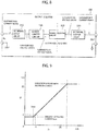
- the relationship between the input voltage V1 and the output voltage V2 of the lower limiter circuit 150 has such characteristics as illustrated in FIG. 2A .
- the relationship between the input DC current signal I1 and the output DC current signal I2 of the output isolator 100 has such characteristics as illustrated in FIG. 2B .
- the lower limit voltage value Vmin is higher than or equal to the value of the voltage V2 at which the value of the DC current signal I2 output by the direct-current signal output circuit 130 is Imin and has substantially no influence upon the DC current signal of 4 to 20 mA.
- a DC current signal whose value is at least, i.e., larger than or equal to the minimum operating current value Imin, is output from the output isolator 100.
- the output isolator 100 of this configuration separates a communication signal and a DC current signal by the capacitor Ci from an electric signal input to the input terminal of the system side, and isolatingly transmits the communication signal to the field side by the communication signal isolating circuit 140.
- the DC current signal of 4 to 20 mA is converted by the direct-current signal input circuit 110 into, e.g., a DC voltage signal of 1 to 5 V, and isolatingly transmitted to the field side by the direct-current signal isolating circuit 120 through the lower limiter circuit 150. Then, the DC voltage signal of 1 to 5 V is converted by the direct-current signal output circuit 130 into a DC current signal of 4 to 20 mA.
- the communication signal and the DC current signal of 4 to 20 mA, which are isolatingly transmitted to the field side are superimposed on each other again and output from an output terminal.
- FIG. 3 is a diagram illustrating an example of a practical circuit configuration of each block of the output isolator 100 according to this embodiment.
- the output isolator 100 is not limited to the example whose circuit configuration is illustrated in this figure, and can be configured by various circuits implementing each block.
- the direct-current signal input circuit 110 is configured by a resistor Ri converting the DC current signal I1 into the DC voltage signal V1, and a buffer.
- the direct-current signal isolating circuit 120 is configured by a pulse width modulator (PWM) 121 converting the DC voltage signal V2 into a pulse width signal, a photocoupler 122 optically transmitting a pulse signal, and a low-pass filter (LPF) 123 converting a pulse signal into a DC voltage signal V2.
- PWM pulse width modulator
- LPF low-pass filter
- the direct-current signal output circuit 130 configures a constant current circuit using a transistor Tr, a resistor Ro, and an operational amplifier so as to convert the DC voltage signal V2 into a DC current signal I2.
- the communication signal isolating circuit 140 is configured using an isolation transformer.
- a general circuit is employed as the lower limiter circuit 150, which uses a power-supply voltage source, an operational amplifier, resistors R1, R2, and R3, and a diode D1.
- the lower limiter circuit 150 sets a power-supply voltage at Vmin so that a lower limit voltage value is Vmin.
- Vmin a lower limit voltage value
- the output isolator 100 can supply a minimum operating current of the valve positioner 420 to the valve positioner 420 even when the DCS 410 malfunctions and cannot supply the minimum operating current to the valve positioner 420 as shown in FIG. 4 . Accordingly, the valve positioner 420 can be operated.
- valve positioner 420 can appropriately be controlled by connecting a communication device 440, such as a handled information terminal apparatus, between the output isolator 100 and the valve positioner 420 utilizing an existing wiring and by then causing the communication device 440 to transmit a communication signal to the valve positioner 420. Consequently, a plant can safely be shut down at low cost without performing a troublesome operation using a manual operation device.
- a communication device 440 such as a handled information terminal apparatus
- the invention is not limited to the above embodiment.
- the lower limiter circuit 150 may be provided on the field side, as illustrated in FIG. 5 .
- the lower limiter circuit 150 is provided between the direct-current signal isolating circuit 120 and the direct-current signal output circuit 130 so that the lower limit value Vmin is output to the direct-current signal output circuit 130 if the value of the output voltage V1 of the direct-current signal isolating circuit 120 is less than the lower limit voltage value Vmin.
- the lower limiter circuit 150 outputting the lower limit voltage value Vmin is used in the above embodiment, a current lower limiter circuit employing a minimum operating current value Imin as the lower limit current value may be used.
- a current lower limiter circuit 160 is arranged at the preceding stage of the direct-current signal input circuit 110 on the system side.
- a current lower limiter circuit 160 is arranged at the subsequent stage of the direct-current signal output circuit 130 on the field side.
- an output isolator 200 converts a superimposed current signal obtained by superimposing a DC current signal and a communication signal on each other into a superimposed voltage signal at a signal input circuit 210.
- the superimposed voltage signal is input to a signal isolating circuit 220 through a lower limiter circuit 150, and the signal isolating circuit 220 isolatingly transmits the input superimposed voltage signal from the system side to the field side. Then, the superimposed voltage signal transmitted to the field side is converted into a superimposed current signal at a signal output circuit 230 and the superimposed current signal is output from the signal output circuit 230.
- an upper limit function of limiting the output voltage V2 up to an upper limit voltage Vmax may be added to the lower limiter circuit 150.
- the value of the voltage V2 at which the value of the DC current signal I2 output by the direct-current signal output circuit 130 is an operation guaranteeing maximum current lmax of a control target apparatus, is set as the upper limit voltage value Vmax.
- the relationship between the input DC current signal I1 and the output DC current signal I2 of the output isolator 100 has such characteristics as illustrated in FIG. 9 .
- the invention can be applied to the case of inputting, from the control-side apparatus such as the DCS to the output isolator, electric signal obtained by superimposing a DC voltage signal of 1 to 5 V and a communication signal on each other.
- it is advised to replace, with an input buffer, the direct-current signal input circuit 110 converting a DC current signal into a DC voltage signal.
Landscapes
- Engineering & Computer Science (AREA)
- Power Engineering (AREA)
- Computer Networks & Wireless Communication (AREA)
- Signal Processing (AREA)
- Programmable Controllers (AREA)
- Dc Digital Transmission (AREA)
Claims (4)
- Isolierte Signalübertragungsvorrichtung (100), die konfiguriert ist, um ein elektrisches Signal von einer steuerungsseitigen Vorrichtung (410) zu einer Steuerungszielvorrichtung (420) isoliert zu übertragen, das durch Überlagern eines Kommunikationssignals auf einem Gleichstromsignal erhalten ist, wobei die Vorrichtung aufweist:
eine untere Begrenzungsschaltung (150), die konfiguriert ist, um ein Gleichstromsignal an die Steuerungszielvorrichtung (420) auszugeben, dessen Wert ein vorbestimmter unterer Grenzwert ist, falls ein Wert des Gleichstromsignals von der steuerungsseitigen Vorrichtung (410) kleiner als der vorbestimmte untere Grenzwert ist. - Isolierte Signalübertragungsvorrichtung (100) nach Anspruch 1, wobei
die Steuerungszielvorrichtung (420) das Gleichstromsignal als ein Signal verwendet, das eine Betriebsenergiequelle versorgt; und
der untere Grenzwert ein minimaler Betriebswert der Steuerungszielvorrichtung (420) ist. - Isolierte Signalübertragungsvorrichtung (100) nach Anspruch 1 oder 2, wobei
das Gleichstromsignal ein DC-Stromsignal von 4 bis 20 mA ist. - Isolierte Signalübertragungsvorrichtung (100) nach einem der Ansprüche 1 bis 3, wobei
die untere Begrenzungsschaltung (150) eine obere Grenzfunktion zum Ausgeben eines Gleichstromsignals aufweist, dessen Wert ein vorbestimmter oberer Grenzwert ist, falls ein Wert des Gleichstromsignal von der steuerungsseitigen Vorrichtung (410) den vorbestimmten oberen Grenzwert überschreitet.
Applications Claiming Priority (1)
| Application Number | Priority Date | Filing Date | Title |
|---|---|---|---|
| JP2013210143A JP5924545B2 (ja) | 2013-10-07 | 2013-10-07 | 絶縁型信号伝送装置 |
Publications (2)
| Publication Number | Publication Date |
|---|---|
| EP2858257A1 EP2858257A1 (de) | 2015-04-08 |
| EP2858257B1 true EP2858257B1 (de) | 2018-12-12 |
Family
ID=51846453
Family Applications (1)
| Application Number | Title | Priority Date | Filing Date |
|---|---|---|---|
| EP14187564.1A Active EP2858257B1 (de) | 2013-10-07 | 2014-10-02 | Isolierte Signalübertragungsvorrichtung |
Country Status (3)
| Country | Link |
|---|---|
| US (1) | US9735622B2 (de) |
| EP (1) | EP2858257B1 (de) |
| JP (1) | JP5924545B2 (de) |
Families Citing this family (1)
| Publication number | Priority date | Publication date | Assignee | Title |
|---|---|---|---|---|
| CN108594721B (zh) * | 2018-06-05 | 2023-12-19 | 北京博阳慧源电力科技有限公司 | 一种能自动切换直流输入信号类型的箱变测控装置 |
Family Cites Families (22)
| Publication number | Priority date | Publication date | Assignee | Title |
|---|---|---|---|---|
| US3999084A (en) * | 1975-07-24 | 1976-12-21 | Gte Laboratories Incorporated | Limiting amplifier with adjustable limits |
| JPS62125706A (ja) * | 1985-11-26 | 1987-06-08 | Victor Co Of Japan Ltd | 電圧電流変換回路 |
| JPS63209314A (ja) * | 1987-02-26 | 1988-08-30 | Toshiba Corp | リミツタ回路 |
| WO1997014213A1 (en) * | 1995-10-09 | 1997-04-17 | Philips Electronics N.V. | Limiter circuit |
| JP3619984B2 (ja) * | 1999-08-06 | 2005-02-16 | 横河電機株式会社 | 2線式伝送器 |
| US6882924B2 (en) * | 2003-05-05 | 2005-04-19 | Precision Engine Controls Corp. | Valve flow control system and method |
| JP4297748B2 (ja) * | 2003-08-21 | 2009-07-15 | 日置電機株式会社 | リミッタ回路 |
| WO2005040992A2 (en) * | 2003-10-24 | 2005-05-06 | Square D Company | Intelligent power management control system |
| DE102005001322B4 (de) * | 2005-01-11 | 2010-07-08 | Dspace Digital Signal Processing And Control Engineering Gmbh | Verfahren und Schaltung zur galvanisch getrennten Übertragung eines Signals |
| US7423588B1 (en) * | 2005-05-19 | 2008-09-09 | Pds Electronics, Inc. | Phased array antenna system |
| JP4785627B2 (ja) * | 2006-06-08 | 2011-10-05 | 三洋電機株式会社 | 電動車両用漏電検出回路および電動車両用漏電検出方法 |
| WO2008100294A2 (en) * | 2007-02-13 | 2008-08-21 | Linear Technology Corporation | Measuring cable resistance in system for providing power over communication cable |
| EP2173025A1 (de) * | 2007-06-29 | 2010-04-07 | Murata Manufacturing Co. Ltd. | Schaltstromversorgunseinheit |
| US8207635B2 (en) * | 2009-02-20 | 2012-06-26 | Redwood Systems, Inc. | Digital switch communication |
| WO2010101661A1 (en) * | 2009-03-06 | 2010-09-10 | Amperion Incorporated | Station communications over electrical transmission lines |
| EP2360805B1 (de) * | 2010-02-19 | 2015-08-26 | Hochschule Luzern Technik & Architektur | Elektrisches Energieübertragungssystem eines Fahrzeugs |
| JP2011239362A (ja) * | 2010-04-16 | 2011-11-24 | Yokogawa Electric Corp | 絶縁型信号伝送装置 |
| JP5170165B2 (ja) * | 2010-06-11 | 2013-03-27 | 株式会社村田製作所 | 絶縁型スイッチング電源装置 |
| US8792257B2 (en) * | 2011-03-25 | 2014-07-29 | Power Systems Technologies, Ltd. | Power converter with reduced power dissipation |
| JP5844106B2 (ja) * | 2011-09-28 | 2016-01-13 | 三洋電機株式会社 | 車両用の電源装置とこの電源装置を備える車両 |
| US8896757B2 (en) * | 2012-08-27 | 2014-11-25 | Sony Corporation | Delta-sigma A/D converter, limiter circuit and television receiver |
| FR2998430B1 (fr) * | 2012-11-20 | 2016-01-08 | Thales Sa | Transmission de puissance electrique sur cable de transmission de donnees |
-
2013
- 2013-10-07 JP JP2013210143A patent/JP5924545B2/ja active Active
-
2014
- 2014-10-02 EP EP14187564.1A patent/EP2858257B1/de active Active
- 2014-10-06 US US14/506,788 patent/US9735622B2/en active Active
Non-Patent Citations (1)
| Title |
|---|
| None * |
Also Published As
| Publication number | Publication date |
|---|---|
| EP2858257A1 (de) | 2015-04-08 |
| JP5924545B2 (ja) | 2016-05-25 |
| JP2015076665A (ja) | 2015-04-20 |
| US9735622B2 (en) | 2017-08-15 |
| US20150097421A1 (en) | 2015-04-09 |
Similar Documents
| Publication | Publication Date | Title |
|---|---|---|
| US10944289B2 (en) | Smart power system | |
| RU2444773C1 (ru) | Технологическое полевое устройство с регулируемым стартовым напряжением | |
| US11381091B2 (en) | Processing circuit with multiple power supply ports and electronic device | |
| CN102340137B (zh) | 用于保护模拟输入模块免受过压的装置 | |
| US8878685B2 (en) | Field device | |
| EP1735670A2 (de) | Prozesseinrichtung mit schaltnetzteil | |
| EP2858257B1 (de) | Isolierte Signalübertragungsvorrichtung | |
| US10141883B2 (en) | Input stage for a motor controller, and motor controller, especially for an electric motor | |
| CN205176719U (zh) | 饱和受控回路电流调节器 | |
| EP2045791B1 (de) | Elektronische Vorrichtung | |
| CN110073636B (zh) | 用于加热、通风和空调设备的调节驱动装置 | |
| US10158287B2 (en) | Voltage regulator including a buck converter pass switch | |
| CN101416134B (zh) | 用于抽头变换器的通用输入装置 | |
| JP2021518613A (ja) | フィールド装置ラッチリレーリセット | |
| CN106980261B (zh) | 定位器 | |
| CN105576945B (zh) | 隔离电源控制装置、电源变换装置及其隔离电源控制方法 | |
| US20150301545A1 (en) | Circuit and method for controlling standyby power consumption | |
| DE102012113047A1 (de) | Betriebselektronik für ein Prozessgerät sowie Verfahren zum Betreiben derselben | |
| US20220069820A1 (en) | Safety device, valve arrangement and method | |
| CN112039550A (zh) | 通信装置及其接收单元与发送单元 | |
| US8793001B2 (en) | Parameterization monitoring for analog signal modules | |
| CN112913099A (zh) | 用于控制用电器的能量供应的开关设备 | |
| CN110647100B (zh) | 一种pvg电液比例阀控制系统及控制方法 | |
| CN217181428U (zh) | 电磁铁线圈电流控制装置、机械开关组件和双电源控制器 | |
| CN217985023U (zh) | 开关量处理电路 |
Legal Events
| Date | Code | Title | Description |
|---|---|---|---|
| PUAI | Public reference made under article 153(3) epc to a published international application that has entered the european phase |
Free format text: ORIGINAL CODE: 0009012 |
|
| 17P | Request for examination filed |
Effective date: 20141002 |
|
| AK | Designated contracting states |
Kind code of ref document: A1 Designated state(s): AL AT BE BG CH CY CZ DE DK EE ES FI FR GB GR HR HU IE IS IT LI LT LU LV MC MK MT NL NO PL PT RO RS SE SI SK SM TR |
|
| AX | Request for extension of the european patent |
Extension state: BA ME |
|
| R17P | Request for examination filed (corrected) |
Effective date: 20150916 |
|
| RBV | Designated contracting states (corrected) |
Designated state(s): AL AT BE BG CH CY CZ DE DK EE ES FI FR GB GR HR HU IE IS IT LI LT LU LV MC MK MT NL NO PL PT RO RS SE SI SK SM TR |
|
| RIC1 | Information provided on ipc code assigned before grant |
Ipc: H04B 3/54 20060101AFI20180509BHEP Ipc: G05B 19/042 20060101ALN20180509BHEP |
|
| GRAP | Despatch of communication of intention to grant a patent |
Free format text: ORIGINAL CODE: EPIDOSNIGR1 |
|
| STAA | Information on the status of an ep patent application or granted ep patent |
Free format text: STATUS: GRANT OF PATENT IS INTENDED |
|
| INTG | Intention to grant announced |
Effective date: 20180615 |
|
| GRAS | Grant fee paid |
Free format text: ORIGINAL CODE: EPIDOSNIGR3 |
|
| GRAA | (expected) grant |
Free format text: ORIGINAL CODE: 0009210 |
|
| STAA | Information on the status of an ep patent application or granted ep patent |
Free format text: STATUS: THE PATENT HAS BEEN GRANTED |
|
| AK | Designated contracting states |
Kind code of ref document: B1 Designated state(s): AL AT BE BG CH CY CZ DE DK EE ES FI FR GB GR HR HU IE IS IT LI LT LU LV MC MK MT NL NO PL PT RO RS SE SI SK SM TR |
|
| REG | Reference to a national code |
Ref country code: GB Ref legal event code: FG4D |
|
| REG | Reference to a national code |
Ref country code: CH Ref legal event code: EP |
|
| REG | Reference to a national code |
Ref country code: AT Ref legal event code: REF Ref document number: 1077349 Country of ref document: AT Kind code of ref document: T Effective date: 20181215 |
|
| REG | Reference to a national code |
Ref country code: DE Ref legal event code: R096 Ref document number: 602014037749 Country of ref document: DE |
|
| REG | Reference to a national code |
Ref country code: IE Ref legal event code: FG4D |
|
| REG | Reference to a national code |
Ref country code: NL Ref legal event code: MP Effective date: 20181212 |
|
| REG | Reference to a national code |
Ref country code: LT Ref legal event code: MG4D |
|
| PG25 | Lapsed in a contracting state [announced via postgrant information from national office to epo] |
Ref country code: ES Free format text: LAPSE BECAUSE OF FAILURE TO SUBMIT A TRANSLATION OF THE DESCRIPTION OR TO PAY THE FEE WITHIN THE PRESCRIBED TIME-LIMIT Effective date: 20181212 Ref country code: NO Free format text: LAPSE BECAUSE OF FAILURE TO SUBMIT A TRANSLATION OF THE DESCRIPTION OR TO PAY THE FEE WITHIN THE PRESCRIBED TIME-LIMIT Effective date: 20190312 Ref country code: HR Free format text: LAPSE BECAUSE OF FAILURE TO SUBMIT A TRANSLATION OF THE DESCRIPTION OR TO PAY THE FEE WITHIN THE PRESCRIBED TIME-LIMIT Effective date: 20181212 Ref country code: LT Free format text: LAPSE BECAUSE OF FAILURE TO SUBMIT A TRANSLATION OF THE DESCRIPTION OR TO PAY THE FEE WITHIN THE PRESCRIBED TIME-LIMIT Effective date: 20181212 Ref country code: BG Free format text: LAPSE BECAUSE OF FAILURE TO SUBMIT A TRANSLATION OF THE DESCRIPTION OR TO PAY THE FEE WITHIN THE PRESCRIBED TIME-LIMIT Effective date: 20190312 Ref country code: FI Free format text: LAPSE BECAUSE OF FAILURE TO SUBMIT A TRANSLATION OF THE DESCRIPTION OR TO PAY THE FEE WITHIN THE PRESCRIBED TIME-LIMIT Effective date: 20181212 Ref country code: LV Free format text: LAPSE BECAUSE OF FAILURE TO SUBMIT A TRANSLATION OF THE DESCRIPTION OR TO PAY THE FEE WITHIN THE PRESCRIBED TIME-LIMIT Effective date: 20181212 |
|
| REG | Reference to a national code |
Ref country code: AT Ref legal event code: MK05 Ref document number: 1077349 Country of ref document: AT Kind code of ref document: T Effective date: 20181212 |
|
| PG25 | Lapsed in a contracting state [announced via postgrant information from national office to epo] |
Ref country code: AL Free format text: LAPSE BECAUSE OF FAILURE TO SUBMIT A TRANSLATION OF THE DESCRIPTION OR TO PAY THE FEE WITHIN THE PRESCRIBED TIME-LIMIT Effective date: 20181212 Ref country code: SE Free format text: LAPSE BECAUSE OF FAILURE TO SUBMIT A TRANSLATION OF THE DESCRIPTION OR TO PAY THE FEE WITHIN THE PRESCRIBED TIME-LIMIT Effective date: 20181212 Ref country code: RS Free format text: LAPSE BECAUSE OF FAILURE TO SUBMIT A TRANSLATION OF THE DESCRIPTION OR TO PAY THE FEE WITHIN THE PRESCRIBED TIME-LIMIT Effective date: 20181212 Ref country code: GR Free format text: LAPSE BECAUSE OF FAILURE TO SUBMIT A TRANSLATION OF THE DESCRIPTION OR TO PAY THE FEE WITHIN THE PRESCRIBED TIME-LIMIT Effective date: 20190313 |
|
| PG25 | Lapsed in a contracting state [announced via postgrant information from national office to epo] |
Ref country code: NL Free format text: LAPSE BECAUSE OF FAILURE TO SUBMIT A TRANSLATION OF THE DESCRIPTION OR TO PAY THE FEE WITHIN THE PRESCRIBED TIME-LIMIT Effective date: 20181212 |
|
| PG25 | Lapsed in a contracting state [announced via postgrant information from national office to epo] |
Ref country code: CZ Free format text: LAPSE BECAUSE OF FAILURE TO SUBMIT A TRANSLATION OF THE DESCRIPTION OR TO PAY THE FEE WITHIN THE PRESCRIBED TIME-LIMIT Effective date: 20181212 Ref country code: IT Free format text: LAPSE BECAUSE OF FAILURE TO SUBMIT A TRANSLATION OF THE DESCRIPTION OR TO PAY THE FEE WITHIN THE PRESCRIBED TIME-LIMIT Effective date: 20181212 Ref country code: PL Free format text: LAPSE BECAUSE OF FAILURE TO SUBMIT A TRANSLATION OF THE DESCRIPTION OR TO PAY THE FEE WITHIN THE PRESCRIBED TIME-LIMIT Effective date: 20181212 Ref country code: PT Free format text: LAPSE BECAUSE OF FAILURE TO SUBMIT A TRANSLATION OF THE DESCRIPTION OR TO PAY THE FEE WITHIN THE PRESCRIBED TIME-LIMIT Effective date: 20190412 |
|
| PG25 | Lapsed in a contracting state [announced via postgrant information from national office to epo] |
Ref country code: EE Free format text: LAPSE BECAUSE OF FAILURE TO SUBMIT A TRANSLATION OF THE DESCRIPTION OR TO PAY THE FEE WITHIN THE PRESCRIBED TIME-LIMIT Effective date: 20181212 Ref country code: SM Free format text: LAPSE BECAUSE OF FAILURE TO SUBMIT A TRANSLATION OF THE DESCRIPTION OR TO PAY THE FEE WITHIN THE PRESCRIBED TIME-LIMIT Effective date: 20181212 Ref country code: IS Free format text: LAPSE BECAUSE OF FAILURE TO SUBMIT A TRANSLATION OF THE DESCRIPTION OR TO PAY THE FEE WITHIN THE PRESCRIBED TIME-LIMIT Effective date: 20190412 Ref country code: RO Free format text: LAPSE BECAUSE OF FAILURE TO SUBMIT A TRANSLATION OF THE DESCRIPTION OR TO PAY THE FEE WITHIN THE PRESCRIBED TIME-LIMIT Effective date: 20181212 Ref country code: SK Free format text: LAPSE BECAUSE OF FAILURE TO SUBMIT A TRANSLATION OF THE DESCRIPTION OR TO PAY THE FEE WITHIN THE PRESCRIBED TIME-LIMIT Effective date: 20181212 |
|
| REG | Reference to a national code |
Ref country code: DE Ref legal event code: R097 Ref document number: 602014037749 Country of ref document: DE |
|
| PLBE | No opposition filed within time limit |
Free format text: ORIGINAL CODE: 0009261 |
|
| STAA | Information on the status of an ep patent application or granted ep patent |
Free format text: STATUS: NO OPPOSITION FILED WITHIN TIME LIMIT |
|
| PG25 | Lapsed in a contracting state [announced via postgrant information from national office to epo] |
Ref country code: AT Free format text: LAPSE BECAUSE OF FAILURE TO SUBMIT A TRANSLATION OF THE DESCRIPTION OR TO PAY THE FEE WITHIN THE PRESCRIBED TIME-LIMIT Effective date: 20181212 Ref country code: DK Free format text: LAPSE BECAUSE OF FAILURE TO SUBMIT A TRANSLATION OF THE DESCRIPTION OR TO PAY THE FEE WITHIN THE PRESCRIBED TIME-LIMIT Effective date: 20181212 Ref country code: SI Free format text: LAPSE BECAUSE OF FAILURE TO SUBMIT A TRANSLATION OF THE DESCRIPTION OR TO PAY THE FEE WITHIN THE PRESCRIBED TIME-LIMIT Effective date: 20181212 |
|
| 26N | No opposition filed |
Effective date: 20190913 |
|
| PG25 | Lapsed in a contracting state [announced via postgrant information from national office to epo] |
Ref country code: TR Free format text: LAPSE BECAUSE OF FAILURE TO SUBMIT A TRANSLATION OF THE DESCRIPTION OR TO PAY THE FEE WITHIN THE PRESCRIBED TIME-LIMIT Effective date: 20181212 |
|
| PG25 | Lapsed in a contracting state [announced via postgrant information from national office to epo] |
Ref country code: MC Free format text: LAPSE BECAUSE OF FAILURE TO SUBMIT A TRANSLATION OF THE DESCRIPTION OR TO PAY THE FEE WITHIN THE PRESCRIBED TIME-LIMIT Effective date: 20181212 |
|
| REG | Reference to a national code |
Ref country code: CH Ref legal event code: PL |
|
| PG25 | Lapsed in a contracting state [announced via postgrant information from national office to epo] |
Ref country code: CH Free format text: LAPSE BECAUSE OF NON-PAYMENT OF DUE FEES Effective date: 20191031 Ref country code: LU Free format text: LAPSE BECAUSE OF NON-PAYMENT OF DUE FEES Effective date: 20191002 Ref country code: LI Free format text: LAPSE BECAUSE OF NON-PAYMENT OF DUE FEES Effective date: 20191031 |
|
| REG | Reference to a national code |
Ref country code: BE Ref legal event code: MM Effective date: 20191031 |
|
| PG25 | Lapsed in a contracting state [announced via postgrant information from national office to epo] |
Ref country code: BE Free format text: LAPSE BECAUSE OF NON-PAYMENT OF DUE FEES Effective date: 20191031 |
|
| PG25 | Lapsed in a contracting state [announced via postgrant information from national office to epo] |
Ref country code: IE Free format text: LAPSE BECAUSE OF NON-PAYMENT OF DUE FEES Effective date: 20191002 |
|
| PG25 | Lapsed in a contracting state [announced via postgrant information from national office to epo] |
Ref country code: CY Free format text: LAPSE BECAUSE OF FAILURE TO SUBMIT A TRANSLATION OF THE DESCRIPTION OR TO PAY THE FEE WITHIN THE PRESCRIBED TIME-LIMIT Effective date: 20181212 |
|
| PG25 | Lapsed in a contracting state [announced via postgrant information from national office to epo] |
Ref country code: MT Free format text: LAPSE BECAUSE OF FAILURE TO SUBMIT A TRANSLATION OF THE DESCRIPTION OR TO PAY THE FEE WITHIN THE PRESCRIBED TIME-LIMIT Effective date: 20181212 Ref country code: HU Free format text: LAPSE BECAUSE OF FAILURE TO SUBMIT A TRANSLATION OF THE DESCRIPTION OR TO PAY THE FEE WITHIN THE PRESCRIBED TIME-LIMIT; INVALID AB INITIO Effective date: 20141002 |
|
| PG25 | Lapsed in a contracting state [announced via postgrant information from national office to epo] |
Ref country code: MK Free format text: LAPSE BECAUSE OF FAILURE TO SUBMIT A TRANSLATION OF THE DESCRIPTION OR TO PAY THE FEE WITHIN THE PRESCRIBED TIME-LIMIT Effective date: 20181212 |
|
| P01 | Opt-out of the competence of the unified patent court (upc) registered |
Effective date: 20230603 |
|
| PGFP | Annual fee paid to national office [announced via postgrant information from national office to epo] |
Ref country code: GB Payment date: 20230920 Year of fee payment: 10 |
|
| PGFP | Annual fee paid to national office [announced via postgrant information from national office to epo] |
Ref country code: FR Payment date: 20230920 Year of fee payment: 10 |
|
| PGFP | Annual fee paid to national office [announced via postgrant information from national office to epo] |
Ref country code: DE Payment date: 20230920 Year of fee payment: 10 |