EP2857232B1 - Höhenverstellbare Anhängerkupplung - Google Patents
Höhenverstellbare Anhängerkupplung Download PDFInfo
- Publication number
- EP2857232B1 EP2857232B1 EP14003220.2A EP14003220A EP2857232B1 EP 2857232 B1 EP2857232 B1 EP 2857232B1 EP 14003220 A EP14003220 A EP 14003220A EP 2857232 B1 EP2857232 B1 EP 2857232B1
- Authority
- EP
- European Patent Office
- Prior art keywords
- locking
- carrier
- trailer coupling
- locking pin
- coupling according
- Prior art date
- Legal status (The legal status is an assumption and is not a legal conclusion. Google has not performed a legal analysis and makes no representation as to the accuracy of the status listed.)
- Active
Links
Images
Classifications
-
- B—PERFORMING OPERATIONS; TRANSPORTING
- B60—VEHICLES IN GENERAL
- B60D—VEHICLE CONNECTIONS
- B60D1/00—Traction couplings; Hitches; Draw-gear; Towing devices
- B60D1/01—Traction couplings or hitches characterised by their type
- B60D1/06—Ball-and-socket hitches
-
- B—PERFORMING OPERATIONS; TRANSPORTING
- B60—VEHICLES IN GENERAL
- B60D—VEHICLE CONNECTIONS
- B60D1/00—Traction couplings; Hitches; Draw-gear; Towing devices
- B60D1/24—Traction couplings; Hitches; Draw-gear; Towing devices characterised by arrangements for particular functions
- B60D1/42—Traction couplings; Hitches; Draw-gear; Towing devices characterised by arrangements for particular functions for being adjustable
- B60D1/46—Traction couplings; Hitches; Draw-gear; Towing devices characterised by arrangements for particular functions for being adjustable vertically
-
- B—PERFORMING OPERATIONS; TRANSPORTING
- B60—VEHICLES IN GENERAL
- B60D—VEHICLE CONNECTIONS
- B60D1/00—Traction couplings; Hitches; Draw-gear; Towing devices
- B60D1/58—Auxiliary devices
- B60D1/583—Holding-down means, e.g. holding-down retainers
Definitions
- the invention relates to a height-adjustable trailer hitch.
- EP 2 524 822 A2 is a height-adjustable device for a trailer hitch of a tractor known.
- This consists of a carrier which is guided between two guide rails. In the guide rails holes are provided, in each of which a locking pin can penetrate. These locking pins are axially adjustable, so that the carrier is locked to the guide rail. In this way, a further displacement of the carrier is prevented.
- This trailer hitch has a support which is displaceable between vertical guide rails.
- the support is adjustable by means of a threaded spindle in height.
- a bolt is biased resiliently against the displaceable carrier on one of the guide rails. This bar prevents unwanted falling out of the carrier from the guide rails. After the carrier has no holes or depressions associated with the bolt, this bolt can not be used to hold the carrier at a predetermined altitude. This is also not necessary because the support of the threaded spindle can be kept sufficiently secure at any height.
- a height-adjustable trailer hitch known. This has a support which carries a coupling member and is guided between two guide rails. These guide rails have recesses in which holes are provided, can engage in the movable locking pin. These locking pins are slidably held on the carrier between a release position enabling an adjustment of the carrier and a locking position engaging in the bores. These locking pins are pivotally connected to levers which are hinged to a common, rotatably mounted disc. By turning this disc both locking pins are adjusted synchronously and in opposite directions. An individual adjustment of a locking pin is thus no longer possible.
- a generic, height-adjustable trailer hitch known.
- This also has a support which carries a coupling member.
- This carrier is guided between two guide rails, in which holes are provided.
- movable locking pins can engage, which are slidably supported on the carrier between a release position enabling the adjustment of the carrier and a locking position engaging in the bores.
- a locking pin is held, which is resiliently biased against the carrier and can engage in a bore in the carrier to lock the carrier in this position. In this position, the locking pins are aligned with corresponding holes of the guide rails.
- the locking pin also has a contact surface, with which it rests against a fixedly connected to the guide rail part.
- the invention has for its object to provide a height-adjustable trailer hitch of the type mentioned above, which is characterized by easier handling.
- the trailer coupling according to the invention has at least one displaceable support which carries at least one coupling member. It is irrelevant how this coupling member is formed.
- the carrier is slidably guided between guide rails so that it can only perform a substantially vertical movement. In the guide rails depressions and / or holes are provided, can engage in the locking pin. These locking pins are adjustable between a release position releasing the carrier and a locking position engaging in the recess. In order to adjust the carrier in its altitude, both locking pins must be brought into their release position. Otherwise, the carrier remains locked.
- At least one locking pin is held in at least one of the guide rails, which is resiliently biased against the carrier.
- This locking pin can engage in a locking receptacle provided in the carrier, which is preferably designed as a blind bore.
- This locking receptacle and the locking pin are arranged such that the locking pin with the wells and / or holes of the guide rails are aligned when the at least one locking pin engages in the at least one locking receptacle of the carrier. This does not have to be laboriously searched for the correct altitude of the carrier, in which the locking pins are aligned with the corresponding recesses and / or holes of the wearer.
- the carrier is locked in this position, so that only the locking pin must be adjusted in its locked position.
- the carrier is provided with at least one chamfer to push away the at least one locking pin against the bias of the carrier when moving the carrier.
- the locking pins are first withdrawn into the carrier. In this position, the carrier is held exclusively by the locking pin. By pulling the at least one locking pin out of the carrier, it can be moved freely along the guide rails. Once the carrier has moved even slightly along the guide rails, the carrier itself prevents displacement of the locking pin in the locking receptacle, so that the carrier can be easily removed from the guide rails.
- the locking pin must only withstand the weight of the carrier and clutch and may therefore be correspondingly weak. In particular, the distance to be traveled of the locking pin can be kept small. This has the consequence that the spring preload of the locking pin can also be made weak, so that the locking pin can be easily pushed away when inserting the carrier in the guide rails.
- the locking pin is in no way sufficient.
- the locking pins are provided, which are formed substantially more massive than the locking pin in the rule and also cover a much larger way. Thus, the locking pins can withstand much higher shear forces, which are caused by the additional weight of a coupled trailer.
- At least one of the locking pin in the release position is approximately aligned with a contact surface of the support of the guide rail, which is approximately perpendicular to the direction of displacement the at least one locking pin is aligned. If during the displacement of the carrier relative to the guide rails, the at least one locking pin is aligned with one of the locking pins, the at least one locking pin still remains in its non-locking position, so that the carrier can be easily moved over this position.
- the at least one locking pin is provided below at least one of the locking pins.
- the at least one locking pin can be easily adjusted against its bias to remove the carrier from the guide rails.
- the at least one locking pin in this case in no way interferes with a possible height adjustment of the wearer.
- At least one handle is provided on both locking pins, in each case on the inside end region, via which the respective locking bolt can be adjusted.
- Both locking pins are thus independently movable. In this way, a two-handed operation of the locking pin is realized, which significantly increases the safety of the operator. In particular, it can not happen in this way that the operator holds a hand below the carrier while the carrier is displaceable. This condition can lead to significant crush injuries and is prevented by the special design of the locking pin.
- At least two locking bolts are provided in the carrier, which are each associated with one of the locking pins. These are also independently adjustable. You can be adjusted between a release bolt releasing the unlocking position and the locking pin in its locked position locking position. The locking bolts in turn act independently of each other, whereby the safety of the height-adjustable trailer hitch is improved.
- the locking bolt or the locking pin is displaceable. Since the two locking pins are independent of each other movable, an opposite movement to the inside or outside can be easily realized. In particular, no complicated transmission elements must be provided for this purpose.
- the bolts are each guided in corresponding holes, so that in this way a simple sliding guide is realized.
- the locking pins engage in the locking position, preferably in the blind bore, while they are withdrawn in the release position in the carrier.
- the locking bolts can engage behind the respective locking pin to lock it.
- the locking bolt also pass through a radial groove or a transverse bore of the locking bolt.
- the locking bolts engage in their locking position behind the locking pin.
- the locking pin in the engagement region of the locking bolt must not be formed in a special way.
- the locking bolts are resiliently biased against the locking pin. In this way it is additionally avoided that the locking bolts move automatically and unintentionally in their unlocked position.
- the locking bolts have at least one second handle on their opposite end portions of the locking pin. At this second handle the locking bolt can be easily grasped and transferred to its unlocked position.
- the locking pins have at least one radial depression or groove into which the locking bolts can engage. In this way, a favorable locking of the locking pin results in both directions, so that can be apart from a stop of the locking pin in the region of the guide rails.
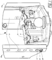
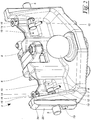
- a height-adjustable trailer hitch 1 according to FIG. 1 has two mutually directed, vehicle-fixed guide rails 2. In these guide rails 2, a series of holes 3 is provided. Between the guide rails 2, a carrier 4 is held vertically adjustable. This carrier 4 has two locking pins 5, which can engage in the holes 3.
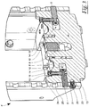
- a locking pin 20 is also supported axially displaceable.
- This locking pin 20 has at its end a protruding collar 21, which can be easily grasped behind with one hand. In this way, the locking pin 21 can pull against a bias to the outside.
- the carrier 4 consists essentially of an L-shaped angle, the vertical leg 6 lies substantially between the guide rails 2. His horizontal leg 7 carries a coupling member 8 in the form of a Spherical head.
- the coupling member 8 is assigned a hold-down 9, which ensures a secure connection with a trailer-side spherical cap.
- the locking pin 5 In the region of its inner end 11, the locking pin 5 has 12 handles. With the help of these handles 12, the locking pin 5 can be moved axially directly and independently.
- locking pin 5 In order to prevent the locking pin 5 inadvertent displacement in an inwardly withdrawn release position, the locking pin 5 radial grooves 13 on. In these radial grooves 13 engage locking bolt 14, which are also axially adjustable. These locking bolts 14 are located in the Figures 2 and 3 in their locked position. They are axially displaceable upwards in an unlocking position 8.
- the carrier 4 can be moved to the desired altitude. Subsequently, the two locking pins 5 are again moved axially outwards, so that they engage in a different bore 3 of the guide rail 2. Due to the resilient bias of the locking pin 14, these automatically get back into engagement with the grooves 13 of the locking pin fifth
- the locking pin 20 is biased by a spring 22.
- This spring 22 presses the locking pin 20 in the illustrated locking position, in which it engages in a locking receptacle 23 of the carrier 4.
- the carrier 4 in held the illustrated position in which the locking pin 5 of the carrier 4 with the holes 3 of the guide rails 2 are aligned.
- the locking pin 5 can be easily transferred from the release position to the locked position.
- the support 4 has a chamfer 24, which cooperates with the locking pin 20.
- this chamfer 24 presses against the locking pin 20 and moves it outwards, so that the carrier 4 can be easily pushed past the locking pin 20.
- the locking pin 20 is not undesirably penetrates into the bore 10 for the locking pin 5, the locking pin 5 are formed such that it is aligned in its release position with a support 4 directed to the bearing surface 25.
- the locking pin 20 remains in its outwardly displaced position, even if it is aligned with the bore 10.
- the two locking pins 5 must first be withdrawn, which are locked by the locking bolt 14. In order to operate the locking pin 14, they have at their upper ends 15 second handle 16.
- the locking pins 14 are resiliently biased against the locking pin 5. By pressing the second handle 16, these are moved against this spring force up until they are completely stepped out in the grooves 13 of the locking pin 5 and reach their unlocked position.
- the locking pin 5 can be moved axially by means of the handle 12 to bring it out of engagement with the holes 3 of the guide rails 2. After doing this at both locking pin 14 and locking pin 5 was, the carrier 4 is held exclusively by the locking pin 20 in height.
- this lock is released, so that the carrier 4 can be pulled down. Once the carrier 4 is slightly shifted down, the locking pin 20 can be released without the risk that this hinders the further movement of the carrier 4.
Landscapes
- Engineering & Computer Science (AREA)
- Transportation (AREA)
- Mechanical Engineering (AREA)
- Fittings On The Vehicle Exterior For Carrying Loads, And Devices For Holding Or Mounting Articles (AREA)
- Body Structure For Vehicles (AREA)
- Vehicle Cleaning, Maintenance, Repair, Refitting, And Outriggers (AREA)
Priority Applications (1)
| Application Number | Priority Date | Filing Date | Title |
|---|---|---|---|
| PL14003220T PL2857232T3 (pl) | 2013-10-01 | 2014-09-17 | Sprzęg przyczepowy o nastawnej wysokości |
Applications Claiming Priority (1)
| Application Number | Priority Date | Filing Date | Title |
|---|---|---|---|
| DE202013008659.9U DE202013008659U1 (de) | 2013-10-01 | 2013-10-01 | Höhenverstellbare Anhängerkupplung |
Publications (3)
| Publication Number | Publication Date |
|---|---|
| EP2857232A2 EP2857232A2 (de) | 2015-04-08 |
| EP2857232A3 EP2857232A3 (de) | 2015-04-29 |
| EP2857232B1 true EP2857232B1 (de) | 2017-01-25 |
Family
ID=51570247
Family Applications (1)
| Application Number | Title | Priority Date | Filing Date |
|---|---|---|---|
| EP14003220.2A Active EP2857232B1 (de) | 2013-10-01 | 2014-09-17 | Höhenverstellbare Anhängerkupplung |
Country Status (3)
| Country | Link |
|---|---|
| EP (1) | EP2857232B1 (pl) |
| DE (1) | DE202013008659U1 (pl) |
| PL (1) | PL2857232T3 (pl) |
Families Citing this family (2)
| Publication number | Priority date | Publication date | Assignee | Title |
|---|---|---|---|---|
| EP3581008A1 (en) * | 2018-06-15 | 2019-12-18 | Cbm - S.P.A. | Device for the connection of a towing vehicle to a trailer |
| DE102018132070B4 (de) * | 2018-12-13 | 2021-10-14 | Pfanzelt Maschinenbau Gmbh | Anhängerkupplung |
Family Cites Families (5)
| Publication number | Priority date | Publication date | Assignee | Title |
|---|---|---|---|---|
| DE2910164C2 (de) * | 1979-03-15 | 1984-05-03 | Xaver Fendt & Co, 8952 Marktoberdorf | Höhenverstellbare Anhängerkupplung |
| ATE56400T1 (de) * | 1987-06-11 | 1990-09-15 | Rockinger Spezial Fab Joh | Hoehenverstellbare anhaengerkupplung. |
| GB2460814A (en) * | 2008-03-12 | 2009-12-16 | Agco Gmbh | A tractor hitch |
| EP2106933B1 (de) * | 2008-04-03 | 2011-06-22 | Deere & Company | Anordnung zur höhenverstellbaren Anbringung einer Anhängekupplung an einem Zugfahrzeug |
| DE202011101206U1 (de) | 2011-05-20 | 2012-08-29 | Hans Sauermann | Höhenverstellbare Anhängerkupplung |
-
2013
- 2013-10-01 DE DE202013008659.9U patent/DE202013008659U1/de not_active Expired - Lifetime
-
2014
- 2014-09-17 EP EP14003220.2A patent/EP2857232B1/de active Active
- 2014-09-17 PL PL14003220T patent/PL2857232T3/pl unknown
Non-Patent Citations (1)
| Title |
|---|
| None * |
Also Published As
| Publication number | Publication date |
|---|---|
| PL2857232T3 (pl) | 2017-10-31 |
| EP2857232A2 (de) | 2015-04-08 |
| EP2857232A3 (de) | 2015-04-29 |
| DE202013008659U1 (de) | 2015-01-07 |
Similar Documents
| Publication | Publication Date | Title |
|---|---|---|
| DE112013007025B4 (de) | Verriegelungsvorrichtung für teleskopierbare Möbelsäule, Möbel und Verfahren | |
| DE202009015413U1 (de) | Wanderstock | |
| EP3235362B1 (de) | Mehrreihige einzelkornsämaschine und verfahren zur einstellung dieser mehrreihigen einzelkornsämaschine | |
| DE202015006833U1 (de) | Knochenstanze mit unverlierbarem Stanzschieber | |
| EP3244774B1 (de) | Verbreiterbarer tisch mit crash-einzugsfunktions | |
| EP2857232B1 (de) | Höhenverstellbare Anhängerkupplung | |
| DE102015121018A1 (de) | Längenverstellbare Samerstange | |
| DE19508089A1 (de) | Hebevorrichtung | |
| DE102014115287B4 (de) | Trägereinrichtung für einen Transportwagen | |
| EP2255694A1 (de) | Kupplungseinrichtung, insbesondere für eine Möbel-Verstelleinrichtung | |
| EP2252510B1 (de) | Vorrichtung zum festlegen eines gegenstandes an einer schiene | |
| DE102009019123B4 (de) | Chirurgisches Instrument mit Rückstellsystem | |
| EP2712777A2 (de) | An einer Anhängerdeichsel befestigbare Stützeinrichtung | |
| DE102005029111B4 (de) | Dachreling für Fahrzeuge | |
| EP2615231A2 (de) | Schiebetüren- oder -fensteranlage mit mindestens zwei als Tür oder Fenster ausgebildeten Schiebeelementen sowie Verriegelungseinrichtung hierfür | |
| EP2524822A2 (de) | Höhenverstellbare Anhängerkupplung | |
| EP2690017A2 (de) | Fixiervorrichtung für einen Ausstattungsgegenstand an einer Fixierschiene | |
| DE10043296B4 (de) | Höhenverstellbare Klapprunge | |
| DE102011010530A1 (de) | Lastaufnahmemittel | |
| DE102008009335B4 (de) | Verbindungssystem zum Festlegen eines Gegenstandes an einer Lochschiene und Verwendung des Verbindungssystems in einem Flugzeug oder Fahrzeug | |
| DE102008010465A1 (de) | Verriegelungsbolzen mit Schlüssel | |
| DE102015106954A1 (de) | Sperrbalken | |
| DE202008002460U1 (de) | Holzspalter | |
| EP2859869B1 (de) | Vorrichtung zur verschieblichen Verbindung eines Fahrgastsitzes mit einer Fahrzeugstruktur | |
| DE102023116613B3 (de) | Schubladenschrank |
Legal Events
| Date | Code | Title | Description |
|---|---|---|---|
| PUAL | Search report despatched |
Free format text: ORIGINAL CODE: 0009013 |
|
| PUAI | Public reference made under article 153(3) epc to a published international application that has entered the european phase |
Free format text: ORIGINAL CODE: 0009012 |
|
| 17P | Request for examination filed |
Effective date: 20140917 |
|
| AK | Designated contracting states |
Kind code of ref document: A2 Designated state(s): AL AT BE BG CH CY CZ DE DK EE ES FI FR GB GR HR HU IE IS IT LI LT LU LV MC MK MT NL NO PL PT RO RS SE SI SK SM TR |
|
| AX | Request for extension of the european patent |
Extension state: BA ME |
|
| AK | Designated contracting states |
Kind code of ref document: A3 Designated state(s): AL AT BE BG CH CY CZ DE DK EE ES FI FR GB GR HR HU IE IS IT LI LT LU LV MC MK MT NL NO PL PT RO RS SE SI SK SM TR |
|
| AX | Request for extension of the european patent |
Extension state: BA ME |
|
| RIC1 | Information provided on ipc code assigned before grant |
Ipc: B60D 1/06 20060101AFI20150324BHEP Ipc: B60D 1/44 20060101ALI20150324BHEP |
|
| R17P | Request for examination filed (corrected) |
Effective date: 20151027 |
|
| RBV | Designated contracting states (corrected) |
Designated state(s): AL AT BE BG CH CY CZ DE DK EE ES FI FR GB GR HR HU IE IS IT LI LT LU LV MC MK MT NL NO PL PT RO RS SE SI SK SM TR |
|
| REG | Reference to a national code |
Ref country code: DE Ref legal event code: R079 Ref document number: 502014002516 Country of ref document: DE Free format text: PREVIOUS MAIN CLASS: B60D0001060000 Ipc: B60D0001460000 |
|
| GRAJ | Information related to disapproval of communication of intention to grant by the applicant or resumption of examination proceedings by the epo deleted |
Free format text: ORIGINAL CODE: EPIDOSDIGR1 |
|
| GRAP | Despatch of communication of intention to grant a patent |
Free format text: ORIGINAL CODE: EPIDOSNIGR1 |
|
| RIN1 | Information on inventor provided before grant (corrected) |
Inventor name: DER ERFINDER HAT AUF SEINE NENNUNG VERZICHTET. |
|
| RIC1 | Information provided on ipc code assigned before grant |
Ipc: B60D 1/46 20060101AFI20160621BHEP Ipc: B60D 1/58 20060101ALI20160621BHEP Ipc: B60D 1/06 20060101ALI20160621BHEP |
|
| GRAP | Despatch of communication of intention to grant a patent |
Free format text: ORIGINAL CODE: EPIDOSNIGR1 |
|
| INTG | Intention to grant announced |
Effective date: 20160801 |
|
| RAP1 | Party data changed (applicant data changed or rights of an application transferred) |
Owner name: SAUERMANN, FRANZ |
|
| GRAS | Grant fee paid |
Free format text: ORIGINAL CODE: EPIDOSNIGR3 |
|
| GRAA | (expected) grant |
Free format text: ORIGINAL CODE: 0009210 |
|
| AK | Designated contracting states |
Kind code of ref document: B1 Designated state(s): AL AT BE BG CH CY CZ DE DK EE ES FI FR GB GR HR HU IE IS IT LI LT LU LV MC MK MT NL NO PL PT RO RS SE SI SK SM TR |
|
| REG | Reference to a national code |
Ref country code: GB Ref legal event code: FG4D Free format text: NOT ENGLISH |
|
| REG | Reference to a national code |
Ref country code: CH Ref legal event code: EP |
|
| REG | Reference to a national code |
Ref country code: AT Ref legal event code: REF Ref document number: 863895 Country of ref document: AT Kind code of ref document: T Effective date: 20170215 |
|
| REG | Reference to a national code |
Ref country code: IE Ref legal event code: FG4D Free format text: LANGUAGE OF EP DOCUMENT: GERMAN |
|
| REG | Reference to a national code |
Ref country code: DE Ref legal event code: R096 Ref document number: 502014002516 Country of ref document: DE |
|
| REG | Reference to a national code |
Ref country code: LT Ref legal event code: MG4D |
|
| REG | Reference to a national code |
Ref country code: NL Ref legal event code: MP Effective date: 20170125 |
|
| PG25 | Lapsed in a contracting state [announced via postgrant information from national office to epo] |
Ref country code: NL Free format text: LAPSE BECAUSE OF FAILURE TO SUBMIT A TRANSLATION OF THE DESCRIPTION OR TO PAY THE FEE WITHIN THE PRESCRIBED TIME-LIMIT Effective date: 20170125 |
|
| PG25 | Lapsed in a contracting state [announced via postgrant information from national office to epo] |
Ref country code: NO Free format text: LAPSE BECAUSE OF FAILURE TO SUBMIT A TRANSLATION OF THE DESCRIPTION OR TO PAY THE FEE WITHIN THE PRESCRIBED TIME-LIMIT Effective date: 20170425 Ref country code: LT Free format text: LAPSE BECAUSE OF FAILURE TO SUBMIT A TRANSLATION OF THE DESCRIPTION OR TO PAY THE FEE WITHIN THE PRESCRIBED TIME-LIMIT Effective date: 20170125 Ref country code: HR Free format text: LAPSE BECAUSE OF FAILURE TO SUBMIT A TRANSLATION OF THE DESCRIPTION OR TO PAY THE FEE WITHIN THE PRESCRIBED TIME-LIMIT Effective date: 20170125 Ref country code: FI Free format text: LAPSE BECAUSE OF FAILURE TO SUBMIT A TRANSLATION OF THE DESCRIPTION OR TO PAY THE FEE WITHIN THE PRESCRIBED TIME-LIMIT Effective date: 20170125 Ref country code: IS Free format text: LAPSE BECAUSE OF FAILURE TO SUBMIT A TRANSLATION OF THE DESCRIPTION OR TO PAY THE FEE WITHIN THE PRESCRIBED TIME-LIMIT Effective date: 20170525 |
|
| PG25 | Lapsed in a contracting state [announced via postgrant information from national office to epo] |
Ref country code: BG Free format text: LAPSE BECAUSE OF FAILURE TO SUBMIT A TRANSLATION OF THE DESCRIPTION OR TO PAY THE FEE WITHIN THE PRESCRIBED TIME-LIMIT Effective date: 20170425 Ref country code: RS Free format text: LAPSE BECAUSE OF FAILURE TO SUBMIT A TRANSLATION OF THE DESCRIPTION OR TO PAY THE FEE WITHIN THE PRESCRIBED TIME-LIMIT Effective date: 20170125 Ref country code: ES Free format text: LAPSE BECAUSE OF FAILURE TO SUBMIT A TRANSLATION OF THE DESCRIPTION OR TO PAY THE FEE WITHIN THE PRESCRIBED TIME-LIMIT Effective date: 20170125 Ref country code: PT Free format text: LAPSE BECAUSE OF FAILURE TO SUBMIT A TRANSLATION OF THE DESCRIPTION OR TO PAY THE FEE WITHIN THE PRESCRIBED TIME-LIMIT Effective date: 20170525 Ref country code: LV Free format text: LAPSE BECAUSE OF FAILURE TO SUBMIT A TRANSLATION OF THE DESCRIPTION OR TO PAY THE FEE WITHIN THE PRESCRIBED TIME-LIMIT Effective date: 20170125 Ref country code: SE Free format text: LAPSE BECAUSE OF FAILURE TO SUBMIT A TRANSLATION OF THE DESCRIPTION OR TO PAY THE FEE WITHIN THE PRESCRIBED TIME-LIMIT Effective date: 20170125 |
|
| REG | Reference to a national code |
Ref country code: FR Ref legal event code: PLFP Year of fee payment: 4 |
|
| REG | Reference to a national code |
Ref country code: DE Ref legal event code: R097 Ref document number: 502014002516 Country of ref document: DE |
|
| PG25 | Lapsed in a contracting state [announced via postgrant information from national office to epo] |
Ref country code: RO Free format text: LAPSE BECAUSE OF FAILURE TO SUBMIT A TRANSLATION OF THE DESCRIPTION OR TO PAY THE FEE WITHIN THE PRESCRIBED TIME-LIMIT Effective date: 20170125 Ref country code: EE Free format text: LAPSE BECAUSE OF FAILURE TO SUBMIT A TRANSLATION OF THE DESCRIPTION OR TO PAY THE FEE WITHIN THE PRESCRIBED TIME-LIMIT Effective date: 20170125 Ref country code: CZ Free format text: LAPSE BECAUSE OF FAILURE TO SUBMIT A TRANSLATION OF THE DESCRIPTION OR TO PAY THE FEE WITHIN THE PRESCRIBED TIME-LIMIT Effective date: 20170125 Ref country code: SK Free format text: LAPSE BECAUSE OF FAILURE TO SUBMIT A TRANSLATION OF THE DESCRIPTION OR TO PAY THE FEE WITHIN THE PRESCRIBED TIME-LIMIT Effective date: 20170125 |
|
| PG25 | Lapsed in a contracting state [announced via postgrant information from national office to epo] |
Ref country code: SM Free format text: LAPSE BECAUSE OF FAILURE TO SUBMIT A TRANSLATION OF THE DESCRIPTION OR TO PAY THE FEE WITHIN THE PRESCRIBED TIME-LIMIT Effective date: 20170125 Ref country code: DK Free format text: LAPSE BECAUSE OF FAILURE TO SUBMIT A TRANSLATION OF THE DESCRIPTION OR TO PAY THE FEE WITHIN THE PRESCRIBED TIME-LIMIT Effective date: 20170125 |
|
| PLBE | No opposition filed within time limit |
Free format text: ORIGINAL CODE: 0009261 |
|
| STAA | Information on the status of an ep patent application or granted ep patent |
Free format text: STATUS: NO OPPOSITION FILED WITHIN TIME LIMIT |
|
| 26N | No opposition filed |
Effective date: 20171026 |
|
| PG25 | Lapsed in a contracting state [announced via postgrant information from national office to epo] |
Ref country code: SI Free format text: LAPSE BECAUSE OF FAILURE TO SUBMIT A TRANSLATION OF THE DESCRIPTION OR TO PAY THE FEE WITHIN THE PRESCRIBED TIME-LIMIT Effective date: 20170125 |
|
| REG | Reference to a national code |
Ref country code: CH Ref legal event code: PL |
|
| PG25 | Lapsed in a contracting state [announced via postgrant information from national office to epo] |
Ref country code: MC Free format text: LAPSE BECAUSE OF FAILURE TO SUBMIT A TRANSLATION OF THE DESCRIPTION OR TO PAY THE FEE WITHIN THE PRESCRIBED TIME-LIMIT Effective date: 20170125 |
|
| REG | Reference to a national code |
Ref country code: IE Ref legal event code: MM4A |
|
| PG25 | Lapsed in a contracting state [announced via postgrant information from national office to epo] |
Ref country code: LU Free format text: LAPSE BECAUSE OF NON-PAYMENT OF DUE FEES Effective date: 20170917 |
|
| PG25 | Lapsed in a contracting state [announced via postgrant information from national office to epo] |
Ref country code: CH Free format text: LAPSE BECAUSE OF NON-PAYMENT OF DUE FEES Effective date: 20170930 Ref country code: LI Free format text: LAPSE BECAUSE OF NON-PAYMENT OF DUE FEES Effective date: 20170930 Ref country code: IE Free format text: LAPSE BECAUSE OF NON-PAYMENT OF DUE FEES Effective date: 20170917 |
|
| REG | Reference to a national code |
Ref country code: FR Ref legal event code: PLFP Year of fee payment: 5 |
|
| PG25 | Lapsed in a contracting state [announced via postgrant information from national office to epo] |
Ref country code: MT Free format text: LAPSE BECAUSE OF FAILURE TO SUBMIT A TRANSLATION OF THE DESCRIPTION OR TO PAY THE FEE WITHIN THE PRESCRIBED TIME-LIMIT Effective date: 20170125 |
|
| PG25 | Lapsed in a contracting state [announced via postgrant information from national office to epo] |
Ref country code: HU Free format text: LAPSE BECAUSE OF FAILURE TO SUBMIT A TRANSLATION OF THE DESCRIPTION OR TO PAY THE FEE WITHIN THE PRESCRIBED TIME-LIMIT; INVALID AB INITIO Effective date: 20140917 |
|
| PG25 | Lapsed in a contracting state [announced via postgrant information from national office to epo] |
Ref country code: CY Free format text: LAPSE BECAUSE OF FAILURE TO SUBMIT A TRANSLATION OF THE DESCRIPTION OR TO PAY THE FEE WITHIN THE PRESCRIBED TIME-LIMIT Effective date: 20170125 |
|
| PG25 | Lapsed in a contracting state [announced via postgrant information from national office to epo] |
Ref country code: MK Free format text: LAPSE BECAUSE OF FAILURE TO SUBMIT A TRANSLATION OF THE DESCRIPTION OR TO PAY THE FEE WITHIN THE PRESCRIBED TIME-LIMIT Effective date: 20170125 |
|
| PG25 | Lapsed in a contracting state [announced via postgrant information from national office to epo] |
Ref country code: GR Free format text: LAPSE BECAUSE OF FAILURE TO SUBMIT A TRANSLATION OF THE DESCRIPTION OR TO PAY THE FEE WITHIN THE PRESCRIBED TIME-LIMIT Effective date: 20170125 |
|
| PG25 | Lapsed in a contracting state [announced via postgrant information from national office to epo] |
Ref country code: AL Free format text: LAPSE BECAUSE OF FAILURE TO SUBMIT A TRANSLATION OF THE DESCRIPTION OR TO PAY THE FEE WITHIN THE PRESCRIBED TIME-LIMIT Effective date: 20170125 |
|
| REG | Reference to a national code |
Ref country code: AT Ref legal event code: MM01 Ref document number: 863895 Country of ref document: AT Kind code of ref document: T Effective date: 20190917 |
|
| PG25 | Lapsed in a contracting state [announced via postgrant information from national office to epo] |
Ref country code: AT Free format text: LAPSE BECAUSE OF NON-PAYMENT OF DUE FEES Effective date: 20190917 |
|
| PGFP | Annual fee paid to national office [announced via postgrant information from national office to epo] |
Ref country code: TR Payment date: 20250910 Year of fee payment: 12 Ref country code: PL Payment date: 20250905 Year of fee payment: 12 |
|
| PGFP | Annual fee paid to national office [announced via postgrant information from national office to epo] |
Ref country code: GB Payment date: 20250923 Year of fee payment: 12 Ref country code: BE Payment date: 20250919 Year of fee payment: 12 |
|
| PGFP | Annual fee paid to national office [announced via postgrant information from national office to epo] |
Ref country code: FR Payment date: 20250925 Year of fee payment: 12 |
|
| PGFP | Annual fee paid to national office [announced via postgrant information from national office to epo] |
Ref country code: DE Payment date: 20250929 Year of fee payment: 12 |
|
| PGFP | Annual fee paid to national office [announced via postgrant information from national office to epo] |
Ref country code: IT Payment date: 20250930 Year of fee payment: 12 |