EP2856897B1 - Schuh - Google Patents
Schuh Download PDFInfo
- Publication number
- EP2856897B1 EP2856897B1 EP14003284.8A EP14003284A EP2856897B1 EP 2856897 B1 EP2856897 B1 EP 2856897B1 EP 14003284 A EP14003284 A EP 14003284A EP 2856897 B1 EP2856897 B1 EP 2856897B1
- Authority
- EP
- European Patent Office
- Prior art keywords
- boot
- strip
- envelope
- user
- distance
- Prior art date
- Legal status (The legal status is an assumption and is not a legal conclusion. Google has not performed a legal analysis and makes no representation as to the accuracy of the status listed.)
- Not-in-force
Links
- 210000002683 foot Anatomy 0.000 claims description 35
- 210000003423 ankle Anatomy 0.000 claims description 19
- 238000004026 adhesive bonding Methods 0.000 claims description 6
- 210000001872 metatarsal bone Anatomy 0.000 claims description 4
- 239000013013 elastic material Substances 0.000 claims description 3
- 230000008878 coupling Effects 0.000 claims 5
- 238000010168 coupling process Methods 0.000 claims 5
- 238000005859 coupling reaction Methods 0.000 claims 5
- 208000010040 Sprains and Strains Diseases 0.000 description 4
- 230000003902 lesion Effects 0.000 description 4
- 230000005540 biological transmission Effects 0.000 description 3
- 239000000463 material Substances 0.000 description 3
- 208000022542 ankle injury Diseases 0.000 description 2
- 239000010985 leather Substances 0.000 description 2
- 229920002994 synthetic fiber Polymers 0.000 description 2
- 208000027418 Wounds and injury Diseases 0.000 description 1
- 238000004873 anchoring Methods 0.000 description 1
- 238000005452 bending Methods 0.000 description 1
- 230000006378 damage Effects 0.000 description 1
- 239000004744 fabric Substances 0.000 description 1
- 208000014674 injury Diseases 0.000 description 1
- 230000003993 interaction Effects 0.000 description 1
- 238000009940 knitting Methods 0.000 description 1
- 210000001699 lower leg Anatomy 0.000 description 1
- 238000000034 method Methods 0.000 description 1
- 239000004033 plastic Substances 0.000 description 1
- 229920003023 plastic Polymers 0.000 description 1
- 239000002985 plastic film Substances 0.000 description 1
- 229920002635 polyurethane Polymers 0.000 description 1
- 239000004814 polyurethane Substances 0.000 description 1
- 230000003449 preventive effect Effects 0.000 description 1
- 230000009023 proprioceptive sensation Effects 0.000 description 1
- 230000001953 sensory effect Effects 0.000 description 1
- 239000007779 soft material Substances 0.000 description 1
- 239000002689 soil Substances 0.000 description 1
- 239000004753 textile Substances 0.000 description 1
- 238000009941 weaving Methods 0.000 description 1
Images


Classifications
-
- A—HUMAN NECESSITIES
- A43—FOOTWEAR
- A43B—CHARACTERISTIC FEATURES OF FOOTWEAR; PARTS OF FOOTWEAR
- A43B7/00—Footwear with health or hygienic arrangements
- A43B7/14—Footwear with health or hygienic arrangements with foot-supporting parts
- A43B7/18—Joint supports, e.g. instep supports
- A43B7/20—Ankle-joint supports or holders
-
- A—HUMAN NECESSITIES
- A43—FOOTWEAR
- A43B—CHARACTERISTIC FEATURES OF FOOTWEAR; PARTS OF FOOTWEAR
- A43B1/00—Footwear characterised by the material
- A43B1/0081—Footwear characterised by the material made at least partially of hook-and-loop type material
-
- A—HUMAN NECESSITIES
- A43—FOOTWEAR
- A43B—CHARACTERISTIC FEATURES OF FOOTWEAR; PARTS OF FOOTWEAR
- A43B19/00—Shoe-shaped inserts; Inserts covering the instep
-
- A—HUMAN NECESSITIES
- A43—FOOTWEAR
- A43B—CHARACTERISTIC FEATURES OF FOOTWEAR; PARTS OF FOOTWEAR
- A43B3/00—Footwear characterised by the shape or the use
- A43B3/34—Footwear characterised by the shape or the use with electrical or electronic arrangements
-
- A—HUMAN NECESSITIES
- A43—FOOTWEAR
- A43B—CHARACTERISTIC FEATURES OF FOOTWEAR; PARTS OF FOOTWEAR
- A43B5/00—Footwear for sporting purposes
-
- A—HUMAN NECESSITIES
- A43—FOOTWEAR
- A43B—CHARACTERISTIC FEATURES OF FOOTWEAR; PARTS OF FOOTWEAR
- A43B5/00—Footwear for sporting purposes
- A43B5/02—Football boots or shoes, i.e. for soccer, football or rugby
-
- A—HUMAN NECESSITIES
- A43—FOOTWEAR
- A43B—CHARACTERISTIC FEATURES OF FOOTWEAR; PARTS OF FOOTWEAR
- A43B5/00—Footwear for sporting purposes
- A43B5/10—Tennis shoes
-
- A—HUMAN NECESSITIES
- A43—FOOTWEAR
- A43B—CHARACTERISTIC FEATURES OF FOOTWEAR; PARTS OF FOOTWEAR
- A43B7/00—Footwear with health or hygienic arrangements
- A43B7/14—Footwear with health or hygienic arrangements with foot-supporting parts
Definitions
- the present invention relates to a shoe, especially a sports shoe.
- Such a shoe can be used especially for tennis, badminton, volleyball, football, baseball, basketball or boxing. These sports involve risks of ankle injuries, such as sprains.
- US 4,513,520 discloses a ski boot that includes a rigid outer shell.
- US-B-8302329 discloses a basketball shoe with a support strap anchored to the side of the shoe and surrounding the rear portion of the shoe. This band is attached to the front of the foot by laces. The support band allows the rear part of the shoe, in case of lateral movement of the foot, to maintain the foot so as to stabilize it.
- the retaining band limits sprains of the ankle, by opposing the inversion movement of the foot, which carries the plantar surface inward, that is to say medially, by lifting the medial edge of the foot .
- This action of the holding band does not allow, in case of beginning of inversion movement of the foot, to prevent this movement amplifies and brings the foot into a position likely to cause an injury to the ankle.
- the support band is not effective enough to prevent the ankle from bending.
- the invention more particularly intends to remedy by proposing a shoe that makes it possible to prevent the appearance of ankle injuries.
- the invention also seeks to improve proprioception, that is to say to lead a user to better perceive the sensory information from the ground to the foot, ankle, or lower leg. It is to make more perceptible the interactions between the soil and the shoe.
- the first portion of the band extends on the lateral side of the shoe.
- the user when the foot of the user begins an inversion movement, the user receives, via the tape, information relating to the position of his ankle. Automatically, the user corrects his movement to prevent the inversion movement from increasing. In this way, the band avoids lesions of the ankle, in particular sprains, in a preventive manner, that is to say that the user corrects by itself its movement before the lesion is initiated.
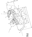
- the Figures 1 to 3 show a shoe 1 provided to accommodate the foot of a user.
- the shoe 1 is adapted for the practice of sport, especially tennis, basketball or boxing.
- the invention also applies to other types of shoes.
- the shoe 1 extends in length between a heel 11 and a front end 12, and in width between a lateral side 13 and a medial side 14.
- X denotes a longitudinal geometric axis of the boot 1, extending between the heel 11 and the front end 12.
- the shoe 1 comprises a rod 2, provided to surround the foot of the user, and a sole 3 which comprises several layers 31, 32, 33 and 34.
- the rod 2 delimits a volume V for receiving the foot of a user, and comprises an outer envelope 4 and an inner liner 6, or first envelope, housed inside the outer envelope 4.
- the terms inside and outside are relative to the volume V.
- An inner element delimits the volume V, and an outer element is located outside the volume V.
- the outer casing 4 of the rod 2 comprises a lateral quarter 41 and a medial quarter 42 secured by their base to a first mounting flange 31, for example by means of a seam, in particular of the Strobel type.
- the outer shell 4 of the rod 2 is secured to an outer sole 32, for example by gluing.
- the outsole 32 includes a midsole 32.1 and a wear layer 32.2.
- the outer casing 4 of the rod 2 is low, that is to say, it is intended to cover only the foot of the user, not the lower leg.
- the lateral quarter 41 and the medial quarter 42 of the outer casing 4 each comprise a notch 40 provided to circumvent the malleolus of the user.
- the outer casing 4 has an opening 43 extending between the lateral quarter 41 and the medial quarter 42 and provided to allow the user to thread the shoe 1.
- Clamping means are provided for clamping the rod 2 on the foot of the user, reversibly.
- the clamping means comprise holes 44 and 45 formed in the outer casing 4 of the rod 2, along the slot 43.
- the holes 44 are disposed on the lateral side 13 and the holes 45 are arranged on the medial side 14.
- the tightening means also comprise a lace 5 which winds through the holes 44 and 45.
- a tensioning of the lace 5 allows a tightening of the rod 2 by mutual approximation of the lateral quarter 41 and the medial quarter 42 of the outer casing 4 of the rod 2.
- the holes 44 and 45 and / or the lace 5 may be replaced by other clamping means, such as hooks.
- the inner liner 6 comprises a lower portion 61 covered by the outer shell 4 and provided to surround the foot of the user, and a generally tubular upper portion 62 intended to surround the bottom of the leg, and particularly cover the malleoli .
- the upper portion 62 protrudes from the outer shell 4.
- the lower portion 61 comprises a lateral portion 63 and a medial portion 64 secured by their base to a second mounting flange 33, for example by means of a seam, in particular of the Strobel type.
- a sockliner 34 is disposed inside the volume V, over the second mounting flange 33.
- the free end 62.1 of the upper portion 62 defines an opening for the passage of the foot of the user, when he puts on the shoe 1.
- the upper portion 62 surrounds the lower leg and ankle.
- An information transmission band 7 comprises a first end 7.1 fixed at the junction between the rod 2 and the sole assembly 3, for example by means of a seam or by gluing.
- the first end 7.1 is located on the lateral side 13 of the shoe, at a zone Z of the boot 1 provided to receive the metatarsal foot of the user.
- Zone Z extends along the X axis between a first terminal Z1 and a second terminal Z2.
- the first terminal Z1 is located at a distance D1 of the heel 11, measured parallel to the X axis, from the heel 11, which is greater than or equal to 60% of the total length L of the shoe 1, measured parallel to the X axis between the heel 11 and the front end 12.
- the second terminal Z2 is located at a distance D2 of the heel 11, measured parallel to the X axis, from the heel 11, which is less than or equal to 85% the total length L of the shoe 1.
- a distance D2 of less than or equal to 75% can be provided.
- the distance D1 is strictly less than the distance D2.
- the zone Z is an anchoring zone of the first end 7.1 of the strip 7, that is to say that the first end 7.1 of the strip 7 is included in the zone Z.
- the width of the strip 7 , at the first end 7.1, is less than or equal to the length D2 - D1 of the zone Z.
- the band 7 comprises a first portion 71 which extends from the first end 7.1 and which is located between the outer shell 4 and the inner liner 6 of the rod 2.
- the first portion 71 is fixed to the inner liner 6 by fixing means extending along the first portion 71, for example by means of seams 74.
- the first portion 71 is concealed under the outer shell 4 and extends in a direction D which comprises an axial component A parallel to the axis X and directed in a direction from the front end 12 to the heel 11.
- the direction D also comprises a component B parallel to a Y axis generally perpendicular to the plane of the sole 3.
- the Y axis is generally parallel to the leg of the user.
- the component B is oriented upwards along the Y axis when the shoe 1 rests on a horizontal surface.
- the band 7 comprises a second portion 72 which extends the first portion 71, outside the outer casing 4, and which is not fixed to the rod 2.
- the second portion is provided to wrap around the upper portion 62 of the inner liner 6, so as to grip the upper portion 62 and the bottom of the leg of the user.
- the second portion 72 ends with a free end 7.2, opposite to the first end 7.1.
- first attachment means 73.1 such as hooks of a self-gripping tape or Velcro (registered trademark), intended to hold on to the ends of the free end.
- second attachment means 73.2 secured to the inner liner 6, such as the velvet of a second self-gripping band.
- the outer shell 4 of the rod 2 is made from a relatively soft material such as a layer or a superposition of several layers, which may be of natural or synthetic material.
- a layer may be made of leather, polyurethane sheet or equivalent material, son assembled to each other mechanically, or other.
- the inner liner 6 is made from a relatively and slightly elastic material, including for example synthetic yarns joined together mechanically, according to techniques such as weaving, knitting, or the like, so as to follow the movements of the foot and ankle.
- the strip 7 is made from a flexible and inextensible material, for example a braided or woven webbing, a plastic web, or the like.
- the band 7 is slightly extensible, which provides better comfort to the user. In all cases, the band 7 is less elastic than the inner shoe 6 to which it is attached.
- the operation is as follows.
- the user detaches the free end 7.2 of the band 7 of the second attachment means, and then inserts his foot into the inner liner 6, at the free end. Once the foot in place in the inner liner 6, the user catches the free end 7.2 of the band 7 to wrap around the upper portion 62 of the inner liner 6, so as to grip his ankle and the bottom of his leg. Then, the user makes cooperate the first and second attachment means, for example by exerting pressure on the first attachment means.
- the strip 7 is movable between a first position, represented at figure 2 , where the free end 7.2 of the strip 7 is not attached to the inner liner 6, and a second position, shown in FIG. figure 1 , where the band 7 at least partially surrounds the upper portion 62 of the inner liner 6 and is attached to the upper portion 62.
- the second portion 72 of the strip 7 describes a circular arc portion, around the Y axis, of angle ⁇ greater than 180 °, preferably greater than 270 °.
- the band 7 extends on the lateral side of the shoe 1, beyond a longitudinal median plane P of the shoe, which passes through the X axis and which shares the shoe 1 in a lateral part and a medial part.
- the band 7 When using the shoe 1, for example for the practice of tennis, when the foot of the user begins a reversal movement, the band 7, which is little or not elastic, is mechanically stressed by the foot of the user. This mechanical stress is transmitted to the ankle and the lower leg via the band 7. Thus, the user receives, through the band 7, information relating to the position of his ankle. Automatically, the user can correct his movement to prevent the inversion movement increases. In this way, the band 7 avoids lesions of the ankle, in particular sprains, preventively, that is to say that the user corrects by itself its movement before the lesion is initiated.
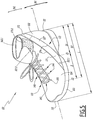
- FIGS. 4 to 6 show a shoe 101.
- elements similar to those of Figures 1 to 3 bear the same numerical references, increased by 100.
- the shoe 101 extends in length between a heel 111 and a front end 112, and in width between a lateral side 113 and a medial side 114.
- Note X are longitudinal axis.
- the shoe 101 includes a rod 102, provided to surround the foot of the user, and a sole 103 which comprises several soles 131, 132, and 134.
- the rod 102 defines a volume V for receiving the foot of a user, and comprises an outer envelope 104 or first envelope.
- the shoe 101 does not have an inner liner housed inside the outer casing 104.
- the outer casing 104 of the rod 102 comprises a lateral portion 141 and a medial quarter 142 secured by their base to a first mounting flange 131, for example by means of a seam, in particular of the Strobel type.
- the outer casing 104 of the rod 102 is secured to an outer sole 132, for example by gluing.
- the outsole 132 includes a midsole 132.1 and a wear layer 132.2.
- the outer casing 104 of the rod 102 comprises a lower portion 161 provided to surround the user's foot, and a generally tubular upper portion 162 provided to surround the bottom of the leg, and in particular cover the malleoli.
- a sockliner 134 is disposed inside the volume V, over the first mounting flange 131.
- the free end 162.1 of the upper portion 162 defines an opening for the passage of the foot of the user, when he puts on the shoe 101.
- the upper part 162 surround the bottom of the leg.
- the outer casing 104 has a slot 143 extending between the lateral quarter 141 and the medial quarter 142 and provided to allow the user to thread the shoe 101.
- Clamping means 105, 144 and 145 are provided for clamping the rod 102 on the foot of the user, reversibly.
- An information transmission band 107 comprises a first end 107.1 fixed at the junction between the rod 102 and the sole assembly 103, for example by means of a seam or by gluing.
- the first end 107.1 is located on the lateral side 113 of the shoe, at a zone Z of the boot 1 designed to receive the metatarsals of the user's foot and similar to the zone Z described with reference to the first embodiment. .
- the band 107 comprises a first portion 171 which extends from the first end 107.1 and which is fixed to the lower portion 161 of the rod 102, for example by means of seams 174 extending along the first portion, at the anchor zone Z.
- the strip 107 comprises a second portion 172 which extends the first portion 171 and which is intended to wrap around the upper portion 162, so as to grip the upper portion 162 and the lower leg of the user.
- the second portion 172 ends with a free end 107.2, opposite to the first end 107.1.
- the inner face of the second portion 172 is provided, on the side of the free end, with first attachment means 173.1 provided for hooking on second attachment means 173.2 secured to the upper portion 162 of the rod 102.
- the outer casing 4 of the upper 2 is made of a relatively soft and slightly elastic material, which contains one or more layers of natural or synthetic materials such as leather, fabric, plastic sheet, so to follow the movements of the foot and ankle.
- the strip 107 is made from a flexible and inextensible material, for example a textile strap or any equivalent.
- the band 107 is slightly extensible, which provides a better comfort to the user. In all cases, the band 107 is less elastic than the outer casing 104 to which it is attached.
- the operation is similar to that of the boot 1.
- the user detaches the free end 107.2 of the band 107 of the second attachment means, then inserts his foot in the upper portion 162 of the rod 102, at the level of the free end 162.1. Once the foot in place in the outer casing 104, the user catches the free end 107.2 of the band 107 to wind it around the upper portion 162 of the outer casing 104, so as to grip his ankle and the bottom of his leg. Then, the user makes cooperate the first and second attachment means.
- the band 107 is movable between a first position, shown in FIG. figure 5 , where the free end 107.2 of the strip 107 is not attached to the rod 102, and a second position, shown in FIG. figure 4 , where the band 107 at least partially surrounds the upper portion 162 of the rod 102 and is attached to the upper portion 162.
Landscapes
- Health & Medical Sciences (AREA)
- General Health & Medical Sciences (AREA)
- Physical Education & Sports Medicine (AREA)
- Epidemiology (AREA)
- Public Health (AREA)
- Engineering & Computer Science (AREA)
- Microelectronics & Electronic Packaging (AREA)
- Footwear And Its Accessory, Manufacturing Method And Apparatuses (AREA)
Claims (10)
- Schuh (1), umfassend:- eine Besohlung (3),- einen Schaft (2), der eine erste Hülle (6) umfasst, die Folgendes umfasst:wobei der Schuh (1) ein Informationsübertragungsband (7) umfasst, das Folgendes umfasst:- einen unteren Abschnitt (61), der dazu vorgesehen ist, den Fuß eines Benutzers zu umgeben,- einen oberen Abschnitt (62), der dazu vorgesehen ist, den Knöchel oder den Knöchel und einen Teil des Unterschenkels des Benutzers zu umgeben,- einen ersten Abschnitt (71), der durch Befestigungsmittel (74) fest mit der Besohlung (3) und/oder dem unteren Abschnitt (61) der ersten Hülle (6) verbunden ist,- einen zweiten Abschnitt (72), der in der Lage ist, sich um den oberen Abschnitt (62) der ersten Hülle (6) zu wickeln, den ersten Abschnitt (71; 72) verlängert und erste Befestigungsmittel (73.1) aufweist, die geeignet sind, mit zweiten Befestigungsmitteln (73.2) zusammenzuwirken, die fest mit dem oberen Abschnitt (62; 162) der ersten Hülle (6; 104) verbunden sind,wobei der Schaft (2) ferner eine äußere Hülle (4) umfasst und die erste Hülle (6) innerhalb der äußeren Hülle (4) sitzt und ein inneres Volumen (V) des Schuhs (1) begrenzt, dadurch gekennzeichnet, dass die äußere Hülle (4) aus einem relativ wiechen und leicht elastischen Material hergestellt ist.
- Schuh (1) nach Anspruch 1, dadurch gekennzeichnet, dass sich der erste Abschnitt (71) des Bands (7) von der lateralen Seite des Schuhs (1) erstreckt.
- Schuh (1) nach Anspruch 1 oder 2, dadurch gekennzeichnet, dass der zweite Abschnitt (72) des Bands (7) zwischen einer ersten Position (Figur 1; Figur 4), in der der zweite Abschnitt (72) des Bands (7) nicht an der ersten Hülle (6) befestigt ist, und einer zweiten Position (Figur 2; Figur 5), in der der zweite Abschnitt (72) des Bands (7) den oberen Abschnitt (62) der ersten Hülle (6) mindestens teilweise umgibt, beweglich ist.
- Schuh (1) nach Anspruch 3, dadurch gekennzeichnet, dass die ersten Befestigungsmittel (73.1) in der zweiten Position (Figur 2; Figur 5) mit den zweiten Befestigungsmitteln (73.2) zusammenwirken.
- Schuh (1) nach einem der Ansprüche 3 oder 4, dadurch gekennzeichnet, dass der zweite Abschnitt (72) des Bands (7) in der zweiten Position einen Kreisbogenabschnitt mit einem Winkel (α) größer 180°, vorzugsweise größer 270°, beschreibt.
- Schuh (1) nach einem der Ansprüche 3 bis 5, dadurch gekennzeichnet, dass sich das Band (7) in der zweiten Position von der lateralen Seite des Schuhs (1) über eine Längsmittelebene (P) des Schuhs hinaus erstreckt.
- Schuh (1) nach einem der vorhergehenden Ansprüche, dadurch gekennzeichnet, dass das Band (7) weniger elastisch als die erste Hülle (6) ist.
- Schuh (1) nach einem der vorhergehenden Ansprüche, dadurch gekennzeichnet, dass die Befestigungsmittel (73.1, 73.2) aus Klettbändern bestehen.
- Schuh (1) nach einem der vorhergehenden Ansprüche, dadurch gekennzeichnet, dass ein erstes Ende (7.1) des Bands (7) am Übergang zwischen dem Schaft (2) und der Besohlung (3) beispielsweise mittels einer Naht oder durch Kleben befestigt ist.
- Schuh (1) nach einem der vorhergehenden Ansprüche, dadurch gekennzeichnet, dass ein erstes Ende (7.1) des ersten Abschnitts (71) des Bands (7) an der lateralen Seite (13) des Schuhs (1) an einem Bereich (Z) des Schuhs (1) befestigt ist, der zur Aufnahme der Mittelfußknochen des Fußes des Benutzers vorgesehen ist, wobei sich der Bereich (Z) entlang einer Längsachse (X) des Schuhs (1; 101) zwischen einer ersten Grenze (Z1) und einer zweiten Grenze (Z2) erstreckt, die jeweils in einem ersten Abstand (D1) und in einem zweiten Abstand (D2) von einem Absatz (11) des Schuhs (1) angeordnet sind, und dass der erste Abstand (D1) größer als oder gleich 60% der Gesamtlänge (L) des Schuhs ist und dass der zweite Abstand kleiner als oder gleich 85% der Gesamtlänge (L) des Schuhs (1) ist, wobei der erste Abstand (D1) strikt kleiner als der zweite Abstand (D2) ist.
Applications Claiming Priority (1)
| Application Number | Priority Date | Filing Date | Title |
|---|---|---|---|
| FR1302298A FR3011445B1 (fr) | 2013-10-03 | 2013-10-03 | Chaussure |
Publications (2)
| Publication Number | Publication Date |
|---|---|
| EP2856897A1 EP2856897A1 (de) | 2015-04-08 |
| EP2856897B1 true EP2856897B1 (de) | 2018-07-11 |
Family
ID=49667228
Family Applications (1)
| Application Number | Title | Priority Date | Filing Date |
|---|---|---|---|
| EP14003284.8A Not-in-force EP2856897B1 (de) | 2013-10-03 | 2014-09-23 | Schuh |
Country Status (7)
| Country | Link |
|---|---|
| US (1) | US9668534B2 (de) |
| EP (1) | EP2856897B1 (de) |
| JP (1) | JP2015071039A (de) |
| CN (1) | CN104510076A (de) |
| AR (1) | AR097908A1 (de) |
| AU (1) | AU2014240257A1 (de) |
| FR (1) | FR3011445B1 (de) |
Families Citing this family (14)
| Publication number | Priority date | Publication date | Assignee | Title |
|---|---|---|---|---|
| DE102016215263A1 (de) * | 2016-08-16 | 2018-02-22 | Adidas Ag | Schuhoberteil für einen Schuh |
| CN107048579A (zh) * | 2017-04-26 | 2017-08-18 | 浙江工贸职业技术学院 | 一种增压登山鞋 |
| DE102017109877A1 (de) * | 2017-05-08 | 2018-11-08 | Betterguards Technology Gmbh | Fußbewegungsdämpfungsvorrichtung und Schuh zum Dämpfen einer Fußbewegung über das Sprunggelenk |
| TWI657810B (zh) * | 2018-03-02 | 2019-05-01 | 許文華 | 矯正功能性扁平足之仿赤足鞋 |
| EP4183289A1 (de) | 2018-04-13 | 2023-05-24 | NIKE Innovate C.V. | Schuhbefestigungssystem |
| FR3094872B1 (fr) * | 2019-04-10 | 2021-03-19 | Salomon Sas | Chaussure de sport |
| WO2022016180A1 (en) * | 2020-07-17 | 2022-01-20 | Sazzi Ip, Llc | Shoe with improved stability |
| USD1033862S1 (en) | 2022-03-23 | 2024-07-09 | Mountain Origins Design LLC | Footwear |
| USD1008611S1 (en) | 2022-03-23 | 2023-12-26 | Mountain Origins Design LLC | Footwear |
| USD1007826S1 (en) | 2022-03-23 | 2023-12-19 | Mountain Origins Design LLC | Footwear |
| USD1007825S1 (en) | 2022-03-23 | 2023-12-19 | Mountain Origins Design LLC | Footwear |
| USD1007110S1 (en) | 2022-03-23 | 2023-12-12 | Mountain Origins Design LLC | Footwear |
| CN120302908A (zh) * | 2022-12-01 | 2025-07-11 | 耐克创新有限合伙公司 | 具有一体针织鞋面和抓地纱线鞋底的鞋类制品及制造方法 |
| USD1055100S1 (en) * | 2023-03-03 | 2024-12-24 | Nike, Inc. | Display screen with virtual three-dimensional shoe icon or display system with virtual three-dimensional shoe icon |
Citations (1)
| Publication number | Priority date | Publication date | Assignee | Title |
|---|---|---|---|---|
| US4513520A (en) * | 1983-02-25 | 1985-04-30 | Heierling Of Switzerland, Ltd. | Ski boot with inner boot tightening mechanism |
Family Cites Families (26)
| Publication number | Priority date | Publication date | Assignee | Title |
|---|---|---|---|---|
| JPS6187548A (ja) * | 1984-07-27 | 1986-05-02 | マイケル イバニ− | 足首支持装置 |
| US4621648A (en) * | 1984-07-27 | 1986-11-11 | Michael Ivany | Ankle support system |
| US4864741A (en) * | 1988-06-13 | 1989-09-12 | Pierre Beauchemin | Ankle support |
| US4878504A (en) * | 1988-07-22 | 1989-11-07 | Nelson Ronald E | Ankle brace with compression straps |
| US5016623A (en) * | 1990-03-14 | 1991-05-21 | Krahenbuhl Doug W | Ankle support |
| IT225832Y1 (it) * | 1991-06-10 | 1997-01-24 | Arkos Srl | Dispositivo di bloccaggio del piede particolarmente per calzature da t rekking |
| JPH074284B2 (ja) * | 1993-01-29 | 1995-01-25 | 株式会社アシックス | 靴の締め具 |
| FR2702935B1 (fr) * | 1993-03-24 | 1995-06-09 | Salomon Sa | Chaussure pour sport de glisse. |
| US5822887A (en) * | 1993-06-22 | 1998-10-20 | Turner; Gregory D. | Over-the-shoe athletic spat |
| US5588228A (en) * | 1993-09-10 | 1996-12-31 | Nordica S.P.A. | Sports shoe with a reinforcing shell-frame |
| DE4435959C2 (de) * | 1994-10-07 | 1997-09-04 | Goodwell Int Ltd | Snowboardstiefel |
| IT1279316B1 (it) * | 1995-06-14 | 1997-12-09 | Nordica Spa | Dispositivo di sostegno per la caviglia, particolarmente per calzature sportive |
| US5894684A (en) * | 1996-01-26 | 1999-04-20 | Vans, Inc. | Snowboard boot ankle support device |
| US5771608A (en) * | 1996-09-17 | 1998-06-30 | K-Swiss Inc. | Shoe with ankle strap protector |
| US6272772B1 (en) * | 1999-08-24 | 2001-08-14 | Daniel J. Sherman | Footwear support system |
| US6652474B1 (en) * | 1999-10-29 | 2003-11-25 | Patrick J. Quinn | Ankle brace |
| JP2003199602A (ja) * | 2001-10-26 | 2003-07-15 | Mizuno Corp | 足首サポートベルト付きスポーツシューズ |
| JP2005152490A (ja) * | 2003-11-28 | 2005-06-16 | Asics Corp | ベルトにより足にフィットする靴 |
| US7171766B2 (en) * | 2004-03-12 | 2007-02-06 | Bouche Richard T | Ankle and foot stabilization support |
| US7908771B2 (en) * | 2007-09-18 | 2011-03-22 | Nike, Inc. | Removable spat for a shoe |
| FR2951358B1 (fr) * | 2009-10-21 | 2011-11-18 | Salomon Sas | Chaussure a serrage de tige ameliore |
| US8302329B2 (en) * | 2009-11-18 | 2012-11-06 | Nike, Inc. | Footwear with counter-supplementing strap |
| FR2952790B1 (fr) | 2009-11-23 | 2012-01-06 | Salomon Sas | Chaussure a semelage ameliore |
| US9402437B2 (en) * | 2010-06-21 | 2016-08-02 | Under Armour, Inc. | Foot support article |
| EP2717809B1 (de) * | 2011-06-10 | 2016-06-01 | Exo Ligament B.V. | Anordnung mit einem schuh, einem mit dem schuh verbundenen formteil zur unterstützung der fussknöchel und formteilesatz sowie befestigungsmittel zur befestigung am schuh |
| CN202525222U (zh) * | 2012-05-08 | 2012-11-14 | 刘德云 | 一种可保护脚踝的运动鞋 |
-
2013
- 2013-10-03 FR FR1302298A patent/FR3011445B1/fr active Active
-
2014
- 2014-09-23 EP EP14003284.8A patent/EP2856897B1/de not_active Not-in-force
- 2014-09-30 CN CN201410515271.0A patent/CN104510076A/zh active Pending
- 2014-09-30 US US14/501,695 patent/US9668534B2/en not_active Expired - Fee Related
- 2014-10-02 AU AU2014240257A patent/AU2014240257A1/en not_active Abandoned
- 2014-10-03 AR ARP140103687A patent/AR097908A1/es unknown
- 2014-10-03 JP JP2014204397A patent/JP2015071039A/ja active Pending
Patent Citations (1)
| Publication number | Priority date | Publication date | Assignee | Title |
|---|---|---|---|---|
| US4513520A (en) * | 1983-02-25 | 1985-04-30 | Heierling Of Switzerland, Ltd. | Ski boot with inner boot tightening mechanism |
Also Published As
| Publication number | Publication date |
|---|---|
| AR097908A1 (es) | 2016-04-20 |
| FR3011445A1 (fr) | 2015-04-10 |
| US20150096196A1 (en) | 2015-04-09 |
| CN104510076A (zh) | 2015-04-15 |
| JP2015071039A (ja) | 2015-04-16 |
| EP2856897A1 (de) | 2015-04-08 |
| FR3011445B1 (fr) | 2016-02-26 |
| AU2014240257A1 (en) | 2015-04-23 |
| US9668534B2 (en) | 2017-06-06 |
Similar Documents
| Publication | Publication Date | Title |
|---|---|---|
| EP2856897B1 (de) | Schuh | |
| EP2604136B1 (de) | Schuh mit verbesserter Einspannmöglichkeit des Schafts | |
| FR3094872A1 (fr) | Chaussure de sport | |
| US9480299B2 (en) | Slip-on footwear with foot securing system | |
| FR2881627A1 (fr) | Chaussure de sport pour la marche ou la pratique du ski de fond | |
| EP1769692B1 (de) | Schuh, der die Fersenhaltung verbessert | |
| EP0710451B1 (de) | Sportschuh | |
| EP0086909B1 (de) | Einlage für Sportschuhe mit steifer oder halbsteifer Schale | |
| EP2670268A1 (de) | Schuh mit einem verbesserten obermaterial | |
| BE1001409A5 (fr) | Chaussure portee par la partie mediane du pied. | |
| EP2394523A1 (de) | Schuh mit verbessertem Laufkomfort | |
| EP2353418B1 (de) | Schuh mit einem verbesserten oberteil | |
| US20130086818A1 (en) | Footwear with improved tightening of upper | |
| FR2599600A1 (fr) | Chaussure de sport, notamment pour la pratique du golf ou du ski de fond | |
| FR3065153B1 (fr) | Chaussure a tige amelioree | |
| FR3130520A1 (fr) | Article chaussant | |
| WO2012072949A1 (fr) | Chaussure de sport de type a crampons | |
| FR3001616A1 (fr) | Chaussure etanche amelioree | |
| FR2540712A1 (fr) | Chaussure d'athletisme | |
| EP1380220B1 (de) | Sportschuh | |
| FR2856558A1 (fr) | Elements chaussants a languette elastique | |
| FR3110355A1 (fr) | Article chaussant comportant une section transparente, en particulier pour personnes ayant des difficultés à s’exprimer | |
| EP2885992B1 (de) | Schuh, der Mittel zur Feuchtigkeitsableitung umfasst | |
| EP2070432B1 (de) | Sportschuh mit Innenschuh, der mit einem Schutzelement ausgestattet ist | |
| EP2481314A1 (de) | Schuhwerk, dessen Schaft einen hohen Teil umfasst |
Legal Events
| Date | Code | Title | Description |
|---|---|---|---|
| PUAI | Public reference made under article 153(3) epc to a published international application that has entered the european phase |
Free format text: ORIGINAL CODE: 0009012 |
|
| 17P | Request for examination filed |
Effective date: 20140923 |
|
| AK | Designated contracting states |
Kind code of ref document: A1 Designated state(s): AL AT BE BG CH CY CZ DE DK EE ES FI FR GB GR HR HU IE IS IT LI LT LU LV MC MK MT NL NO PL PT RO RS SE SI SK SM TR |
|
| AX | Request for extension of the european patent |
Extension state: BA ME |
|
| R17P | Request for examination filed (corrected) |
Effective date: 20151001 |
|
| 17Q | First examination report despatched |
Effective date: 20161216 |
|
| GRAP | Despatch of communication of intention to grant a patent |
Free format text: ORIGINAL CODE: EPIDOSNIGR1 |
|
| INTG | Intention to grant announced |
Effective date: 20180206 |
|
| GRAS | Grant fee paid |
Free format text: ORIGINAL CODE: EPIDOSNIGR3 |
|
| GRAA | (expected) grant |
Free format text: ORIGINAL CODE: 0009210 |
|
| AK | Designated contracting states |
Kind code of ref document: B1 Designated state(s): AL AT BE BG CH CY CZ DE DK EE ES FI FR GB GR HR HU IE IS IT LI LT LU LV MC MK MT NL NO PL PT RO RS SE SI SK SM TR |
|
| REG | Reference to a national code |
Ref country code: GB Ref legal event code: FG4D Free format text: NOT ENGLISH |
|
| REG | Reference to a national code |
Ref country code: CH Ref legal event code: EP |
|
| REG | Reference to a national code |
Ref country code: AT Ref legal event code: REF Ref document number: 1015988 Country of ref document: AT Kind code of ref document: T Effective date: 20180715 |
|
| REG | Reference to a national code |
Ref country code: IE Ref legal event code: FG4D Free format text: LANGUAGE OF EP DOCUMENT: FRENCH |
|
| REG | Reference to a national code |
Ref country code: DE Ref legal event code: R096 Ref document number: 602014028137 Country of ref document: DE |
|
| REG | Reference to a national code |
Ref country code: NL Ref legal event code: MP Effective date: 20180711 |
|
| REG | Reference to a national code |
Ref country code: LT Ref legal event code: MG4D |
|
| REG | Reference to a national code |
Ref country code: AT Ref legal event code: MK05 Ref document number: 1015988 Country of ref document: AT Kind code of ref document: T Effective date: 20180711 |
|
| PG25 | Lapsed in a contracting state [announced via postgrant information from national office to epo] |
Ref country code: NL Free format text: LAPSE BECAUSE OF FAILURE TO SUBMIT A TRANSLATION OF THE DESCRIPTION OR TO PAY THE FEE WITHIN THE PRESCRIBED TIME-LIMIT Effective date: 20180711 |
|
| PG25 | Lapsed in a contracting state [announced via postgrant information from national office to epo] |
Ref country code: LT Free format text: LAPSE BECAUSE OF FAILURE TO SUBMIT A TRANSLATION OF THE DESCRIPTION OR TO PAY THE FEE WITHIN THE PRESCRIBED TIME-LIMIT Effective date: 20180711 Ref country code: BG Free format text: LAPSE BECAUSE OF FAILURE TO SUBMIT A TRANSLATION OF THE DESCRIPTION OR TO PAY THE FEE WITHIN THE PRESCRIBED TIME-LIMIT Effective date: 20181011 Ref country code: AT Free format text: LAPSE BECAUSE OF FAILURE TO SUBMIT A TRANSLATION OF THE DESCRIPTION OR TO PAY THE FEE WITHIN THE PRESCRIBED TIME-LIMIT Effective date: 20180711 Ref country code: PL Free format text: LAPSE BECAUSE OF FAILURE TO SUBMIT A TRANSLATION OF THE DESCRIPTION OR TO PAY THE FEE WITHIN THE PRESCRIBED TIME-LIMIT Effective date: 20180711 Ref country code: RS Free format text: LAPSE BECAUSE OF FAILURE TO SUBMIT A TRANSLATION OF THE DESCRIPTION OR TO PAY THE FEE WITHIN THE PRESCRIBED TIME-LIMIT Effective date: 20180711 Ref country code: IS Free format text: LAPSE BECAUSE OF FAILURE TO SUBMIT A TRANSLATION OF THE DESCRIPTION OR TO PAY THE FEE WITHIN THE PRESCRIBED TIME-LIMIT Effective date: 20181111 Ref country code: GR Free format text: LAPSE BECAUSE OF FAILURE TO SUBMIT A TRANSLATION OF THE DESCRIPTION OR TO PAY THE FEE WITHIN THE PRESCRIBED TIME-LIMIT Effective date: 20181012 Ref country code: NO Free format text: LAPSE BECAUSE OF FAILURE TO SUBMIT A TRANSLATION OF THE DESCRIPTION OR TO PAY THE FEE WITHIN THE PRESCRIBED TIME-LIMIT Effective date: 20181011 Ref country code: FI Free format text: LAPSE BECAUSE OF FAILURE TO SUBMIT A TRANSLATION OF THE DESCRIPTION OR TO PAY THE FEE WITHIN THE PRESCRIBED TIME-LIMIT Effective date: 20180711 Ref country code: SE Free format text: LAPSE BECAUSE OF FAILURE TO SUBMIT A TRANSLATION OF THE DESCRIPTION OR TO PAY THE FEE WITHIN THE PRESCRIBED TIME-LIMIT Effective date: 20180711 |
|
| PG25 | Lapsed in a contracting state [announced via postgrant information from national office to epo] |
Ref country code: LV Free format text: LAPSE BECAUSE OF FAILURE TO SUBMIT A TRANSLATION OF THE DESCRIPTION OR TO PAY THE FEE WITHIN THE PRESCRIBED TIME-LIMIT Effective date: 20180711 Ref country code: ES Free format text: LAPSE BECAUSE OF FAILURE TO SUBMIT A TRANSLATION OF THE DESCRIPTION OR TO PAY THE FEE WITHIN THE PRESCRIBED TIME-LIMIT Effective date: 20180711 Ref country code: AL Free format text: LAPSE BECAUSE OF FAILURE TO SUBMIT A TRANSLATION OF THE DESCRIPTION OR TO PAY THE FEE WITHIN THE PRESCRIBED TIME-LIMIT Effective date: 20180711 Ref country code: HR Free format text: LAPSE BECAUSE OF FAILURE TO SUBMIT A TRANSLATION OF THE DESCRIPTION OR TO PAY THE FEE WITHIN THE PRESCRIBED TIME-LIMIT Effective date: 20180711 |
|
| REG | Reference to a national code |
Ref country code: DE Ref legal event code: R119 Ref document number: 602014028137 Country of ref document: DE |
|
| PG25 | Lapsed in a contracting state [announced via postgrant information from national office to epo] |
Ref country code: MC Free format text: LAPSE BECAUSE OF FAILURE TO SUBMIT A TRANSLATION OF THE DESCRIPTION OR TO PAY THE FEE WITHIN THE PRESCRIBED TIME-LIMIT Effective date: 20180711 Ref country code: IT Free format text: LAPSE BECAUSE OF FAILURE TO SUBMIT A TRANSLATION OF THE DESCRIPTION OR TO PAY THE FEE WITHIN THE PRESCRIBED TIME-LIMIT Effective date: 20180711 Ref country code: EE Free format text: LAPSE BECAUSE OF FAILURE TO SUBMIT A TRANSLATION OF THE DESCRIPTION OR TO PAY THE FEE WITHIN THE PRESCRIBED TIME-LIMIT Effective date: 20180711 Ref country code: RO Free format text: LAPSE BECAUSE OF FAILURE TO SUBMIT A TRANSLATION OF THE DESCRIPTION OR TO PAY THE FEE WITHIN THE PRESCRIBED TIME-LIMIT Effective date: 20180711 Ref country code: CZ Free format text: LAPSE BECAUSE OF FAILURE TO SUBMIT A TRANSLATION OF THE DESCRIPTION OR TO PAY THE FEE WITHIN THE PRESCRIBED TIME-LIMIT Effective date: 20180711 |
|
| REG | Reference to a national code |
Ref country code: CH Ref legal event code: PL |
|
| PLBE | No opposition filed within time limit |
Free format text: ORIGINAL CODE: 0009261 |
|
| STAA | Information on the status of an ep patent application or granted ep patent |
Free format text: STATUS: NO OPPOSITION FILED WITHIN TIME LIMIT |
|
| PG25 | Lapsed in a contracting state [announced via postgrant information from national office to epo] |
Ref country code: DK Free format text: LAPSE BECAUSE OF FAILURE TO SUBMIT A TRANSLATION OF THE DESCRIPTION OR TO PAY THE FEE WITHIN THE PRESCRIBED TIME-LIMIT Effective date: 20180711 Ref country code: SM Free format text: LAPSE BECAUSE OF FAILURE TO SUBMIT A TRANSLATION OF THE DESCRIPTION OR TO PAY THE FEE WITHIN THE PRESCRIBED TIME-LIMIT Effective date: 20180711 Ref country code: SK Free format text: LAPSE BECAUSE OF FAILURE TO SUBMIT A TRANSLATION OF THE DESCRIPTION OR TO PAY THE FEE WITHIN THE PRESCRIBED TIME-LIMIT Effective date: 20180711 |
|
| REG | Reference to a national code |
Ref country code: BE Ref legal event code: MM Effective date: 20180930 |
|
| 26N | No opposition filed |
Effective date: 20190412 |
|
| GBPC | Gb: european patent ceased through non-payment of renewal fee |
Effective date: 20181011 |
|
| REG | Reference to a national code |
Ref country code: IE Ref legal event code: MM4A |
|
| PG25 | Lapsed in a contracting state [announced via postgrant information from national office to epo] |
Ref country code: LU Free format text: LAPSE BECAUSE OF NON-PAYMENT OF DUE FEES Effective date: 20180923 |
|
| PG25 | Lapsed in a contracting state [announced via postgrant information from national office to epo] |
Ref country code: DE Free format text: LAPSE BECAUSE OF NON-PAYMENT OF DUE FEES Effective date: 20190402 Ref country code: IE Free format text: LAPSE BECAUSE OF NON-PAYMENT OF DUE FEES Effective date: 20180923 |
|
| PG25 | Lapsed in a contracting state [announced via postgrant information from national office to epo] |
Ref country code: LI Free format text: LAPSE BECAUSE OF NON-PAYMENT OF DUE FEES Effective date: 20180930 Ref country code: BE Free format text: LAPSE BECAUSE OF NON-PAYMENT OF DUE FEES Effective date: 20180930 Ref country code: FR Free format text: LAPSE BECAUSE OF NON-PAYMENT OF DUE FEES Effective date: 20180930 Ref country code: SI Free format text: LAPSE BECAUSE OF FAILURE TO SUBMIT A TRANSLATION OF THE DESCRIPTION OR TO PAY THE FEE WITHIN THE PRESCRIBED TIME-LIMIT Effective date: 20180711 Ref country code: CH Free format text: LAPSE BECAUSE OF NON-PAYMENT OF DUE FEES Effective date: 20180930 |
|
| PG25 | Lapsed in a contracting state [announced via postgrant information from national office to epo] |
Ref country code: GB Free format text: LAPSE BECAUSE OF NON-PAYMENT OF DUE FEES Effective date: 20181011 |
|
| PG25 | Lapsed in a contracting state [announced via postgrant information from national office to epo] |
Ref country code: MT Free format text: LAPSE BECAUSE OF FAILURE TO SUBMIT A TRANSLATION OF THE DESCRIPTION OR TO PAY THE FEE WITHIN THE PRESCRIBED TIME-LIMIT Effective date: 20180711 |
|
| PG25 | Lapsed in a contracting state [announced via postgrant information from national office to epo] |
Ref country code: TR Free format text: LAPSE BECAUSE OF FAILURE TO SUBMIT A TRANSLATION OF THE DESCRIPTION OR TO PAY THE FEE WITHIN THE PRESCRIBED TIME-LIMIT Effective date: 20180711 |
|
| PG25 | Lapsed in a contracting state [announced via postgrant information from national office to epo] |
Ref country code: PT Free format text: LAPSE BECAUSE OF FAILURE TO SUBMIT A TRANSLATION OF THE DESCRIPTION OR TO PAY THE FEE WITHIN THE PRESCRIBED TIME-LIMIT Effective date: 20180711 Ref country code: HU Free format text: LAPSE BECAUSE OF FAILURE TO SUBMIT A TRANSLATION OF THE DESCRIPTION OR TO PAY THE FEE WITHIN THE PRESCRIBED TIME-LIMIT; INVALID AB INITIO Effective date: 20140923 |
|
| PG25 | Lapsed in a contracting state [announced via postgrant information from national office to epo] |
Ref country code: MK Free format text: LAPSE BECAUSE OF NON-PAYMENT OF DUE FEES Effective date: 20180711 Ref country code: CY Free format text: LAPSE BECAUSE OF FAILURE TO SUBMIT A TRANSLATION OF THE DESCRIPTION OR TO PAY THE FEE WITHIN THE PRESCRIBED TIME-LIMIT Effective date: 20180711 |