EP2856486B1 - Arbeitszylinder für einen antrieb eines elektrischen leistungsschalters - Google Patents
Arbeitszylinder für einen antrieb eines elektrischen leistungsschalters Download PDFInfo
- Publication number
- EP2856486B1 EP2856486B1 EP13727806.5A EP13727806A EP2856486B1 EP 2856486 B1 EP2856486 B1 EP 2856486B1 EP 13727806 A EP13727806 A EP 13727806A EP 2856486 B1 EP2856486 B1 EP 2856486B1
- Authority
- EP
- European Patent Office
- Prior art keywords
- cylinder
- cylinder head
- drive according
- piston rod
- working cylinder
- Prior art date
- Legal status (The legal status is an assumption and is not a legal conclusion. Google has not performed a legal analysis and makes no representation as to the accuracy of the status listed.)
- Active
Links
Images

Classifications
-
- H—ELECTRICITY
- H01—ELECTRIC ELEMENTS
- H01H—ELECTRIC SWITCHES; RELAYS; SELECTORS; EMERGENCY PROTECTIVE DEVICES
- H01H33/00—High-tension or heavy-current switches with arc-extinguishing or arc-preventing means
- H01H33/02—Details
- H01H33/28—Power arrangements internal to the switch for operating the driving mechanism
- H01H33/30—Power arrangements internal to the switch for operating the driving mechanism using fluid actuator
- H01H33/34—Power arrangements internal to the switch for operating the driving mechanism using fluid actuator hydraulic
-
- H—ELECTRICITY
- H01—ELECTRIC ELEMENTS
- H01H—ELECTRIC SWITCHES; RELAYS; SELECTORS; EMERGENCY PROTECTIVE DEVICES
- H01H3/00—Mechanisms for operating contacts
- H01H3/22—Power arrangements internal to the switch for operating the driving mechanism
- H01H3/24—Power arrangements internal to the switch for operating the driving mechanism using pneumatic or hydraulic actuator
-
- H—ELECTRICITY
- H01—ELECTRIC ELEMENTS
- H01H—ELECTRIC SWITCHES; RELAYS; SELECTORS; EMERGENCY PROTECTIVE DEVICES
- H01H3/00—Mechanisms for operating contacts
- H01H3/22—Power arrangements internal to the switch for operating the driving mechanism
- H01H3/30—Power arrangements internal to the switch for operating the driving mechanism using spring motor
- H01H3/3031—Means for locking the spring in a charged state
-
- H—ELECTRICITY
- H01—ELECTRIC ELEMENTS
- H01H—ELECTRIC SWITCHES; RELAYS; SELECTORS; EMERGENCY PROTECTIVE DEVICES
- H01H3/00—Mechanisms for operating contacts
- H01H3/22—Power arrangements internal to the switch for operating the driving mechanism
- H01H3/30—Power arrangements internal to the switch for operating the driving mechanism using spring motor
- H01H3/3052—Linear spring motors
-
- H—ELECTRICITY
- H01—ELECTRIC ELEMENTS
- H01H—ELECTRIC SWITCHES; RELAYS; SELECTORS; EMERGENCY PROTECTIVE DEVICES
- H01H2221/00—Actuators
- H01H2221/008—Actuators other then push button
-
- H—ELECTRICITY
- H01—ELECTRIC ELEMENTS
- H01H—ELECTRIC SWITCHES; RELAYS; SELECTORS; EMERGENCY PROTECTIVE DEVICES
- H01H2235/00—Springs
- H01H2235/016—Preloading
-
- H—ELECTRICITY
- H01—ELECTRIC ELEMENTS
- H01H—ELECTRIC SWITCHES; RELAYS; SELECTORS; EMERGENCY PROTECTIVE DEVICES
- H01H2239/00—Miscellaneous
- H01H2239/044—High voltage application
-
- H—ELECTRICITY
- H01—ELECTRIC ELEMENTS
- H01H—ELECTRIC SWITCHES; RELAYS; SELECTORS; EMERGENCY PROTECTIVE DEVICES
- H01H3/00—Mechanisms for operating contacts
- H01H3/22—Power arrangements internal to the switch for operating the driving mechanism
- H01H3/30—Power arrangements internal to the switch for operating the driving mechanism using spring motor
- H01H3/3005—Charging means
- H01H3/301—Charging means using a fluid actuator
Definitions
- the invention relates to a working cylinder for driving an electric circuit breaker, in particular for use in medium-voltage or high-voltage switchgear, comprising a main body.
- circuit breakers are switched only a few times within one year of operation, for example when a short circuit occurs.
- the circuit breakers will be installed for several decades. In that regard, a drive of a circuit breaker must show not only a high instantaneous reliability, but also a low maintenance requirement.
- the DE 10 2009 015 881 A1 a hydromechanical drive with a working cylinder, which actuates a circuit breaker by means of a piston rod.
- This drive comprises an energy store and a hydraulic device for transmitting energy stored in the energy store.
- drives are known from the prior art, in which the energy is stored for switching in metal springs of a spring accumulator, wherein the hydraulic device should cause a loss and low-wear transmission of energy during the switching process.
- a hydraulic drive for switching the contact of a gas-insulated switchgear comprising a working cylinder, in which a piston rod is guided, wherein a movable contact member is actuated by the piston rod.
- the working cylinder is composed of an outer cylinder coaxially arranged on the outer peripheral side of a fluid pressure cylinder and a block-like cylinder head. The bottom of the outer cylinder is provided with a stopper. On the cylinder head, a fluid pressure control valve and a piston holding mechanism are mounted.
- a circuit breaker refers to the piston rod is mechanically connected to the guided in a cylinder working piston rod of a hydraulic drive. Within the working cylinder of the hydraulic drive is a spring for applying the energy required for switching the disconnector.
- the hitherto known hydraulic devices have relatively complex constructed working cylinder.
- the known from the prior art drives show one-piece working cylinder with complex structure, which require various attachments such as tank housing, support tubes and damping rings.
- the production of this complex cylinder is extremely expensive and is associated with high costs.
- the running surfaces for a piston rod of the working cylinder are usually anodized. This is associated with a high cost and therefore high costs.
- the use of aluminum can cause cavitation damage, which can cause technical problems.
- the invention is therefore an object of the invention to provide a working cylinder for driving an electric circuit breaker, which shows a high operational capability for trouble-free and cost-effective production and can be combined with existing drives technically problem-free.
- the aforementioned working cylinder is characterized in that the base body is made of a first component, namely a cylinder head, and a second component, namely a cylinder body, which are interconnected.
- the hydraulic device can be easily closed by a separate cylinder head, with other components can be attached to the cylinder head as the core of the drive.
- the cylinder head with all its interfaces for other components can be made independent of the cylinder body.
- a separate cylinder body can also be produced separately and virtually independently of the material of the cylinder head. Any running surfaces for piston rods can be processed independently of the cylinder head.
- a working cylinder is relatively easy to produce modular and can be assembled from two independently manufactured components.
- a working cylinder for driving an electric circuit breaker is indicated, which shows a high operational capability for trouble-free and cost-effective production and can be combined with existing drives technically problem-free.
- the cylinder head is non-positively connected to the cylinder body.
- the two components can be captive and firmly connected.
- the cylinder head and the cylinder body are bolted together. Screw connections are inexpensive and connect the components reversibly releasably together.
- a piston rod is guided in the working cylinder.
- a piston rod a movable contact member of an electrical circuit breaker can be reliably operated.
- the piston rod advantageously has a piston which is in contact with a running surface of the cylinder body. As a result, a tilt-free and low-friction guidance of the piston rod in the working cylinder is possible.
- the piston rod is in contact with the cylinder head.
- the piston rod at least two points in the working cylinder, namely once in the cylinder body and once in the cylinder head out.
- tilting or tilting of the piston rod can be avoided.
- the piston rod is positioned coaxially to the working cylinder and received in a central passage of the working cylinder.
- the piston rod can be easily inserted into the working cylinder from one side.
- a drive for an electrical circuit breaker comprising a mechanical spring accumulator and a hydraulic device for transmitting an energy storable in the spring accumulator, a working cylinder of the type described here.
- the hydraulic device on such a working cylinder.
- Three memory modules a control block, a pressure release lever with Fedenrvegschalter, a pump module with a motor, a fuel cap with a guide bushing, a filling or venting port, an intermediate housing and the cylinder body.
- a stop bolt an overflow valve, at least one check valve, a P-cover, which serves as a guide for a piston rod, various plugs and at least a flange plate.
- the outer contour of the cylinder head is vortelhaft used as a bearing surface for supporting a pressure ring of the spring accumulator.
- Hydraulic interfaces to different components are advantageously created by connecting sockets. This allows hydraulic oil to flow into different components. In the cylinder head itself, the complete volume of the hydraulic oil is advantageously provided.
- a pressure ring On the outer surface of the cylinder body, a pressure ring is advantageously performed. This pressure ring presses on storage piston in a storage module together mechanical springs in the mechanical spring store.
- a bottom plate is advantageously attached to the cylinder body.
- the bottom plate serves as a counter surface for the mechanical springs.
- a connecting bush is arranged between the cylinder head and the cylinder body.
- a channel (alternating pressure) can be connected.
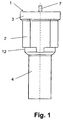
- Fig. 1 shows a working cylinder 1 for a drive, not shown, an electric circuit breaker, in particular an electrical high-voltage circuit breaker comprising a main body 2.
- the main body 2 is constructed in two parts.
- the main body 2 is made of a first component, namely a cylinder head 3, and a second component, namely a cylinder body 4, which are interconnected.
- Fig. 2 shows that the cylinder head 3 is positively connected to the cylinder body 4.
- the cylinder head 3 and the cylinder body 4 are bolted together.
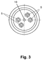
- Fig. 3 shows in a sectional view a preferred embodiment in which four screws 5 are provided.
- a piston rod 7 is guided.
- the piston rod 7 has a piston 8, which is in contact with a running surface 9 of the cylinder body 4.
- the piston rod 7 is also in contact with the cylinder head 3.
- the piston rod 7 is positioned coaxially with the working cylinder 1 and received in a central passage 10 of the working cylinder 1.
- the piston rod 7 runs in the working cylinder 1 up and down.
- a not shown movable contact member of an electric circuit breaker is actuated.
- the cylinder head 3 has a cylindrical recess 11, in which the cylinder body 4 is partially received.
- the cylinder body 4 is designed as a cylindrical component.
- the cylinder head 3 has a stepped outer peripheral surface 12.
Landscapes
- Actuator (AREA)
- Driving Mechanisms And Operating Circuits Of Arc-Extinguishing High-Tension Switches (AREA)
- Gas-Insulated Switchgears (AREA)
- Switch Cases, Indication, And Locking (AREA)
- Circuit Breakers (AREA)
Description
- Die Erfindung betrifft einen Arbeitszylinder für einen Antrieb eines elektrischen Leistungsschalters, insbesondere zur Verwendung in Mittelspannungs- oder Hochspannungsschaltanlagen, umfassend einen Grundkörper.
- In elektrischen Schaltanlagen müssen Leistungsschalter eine elektrische Energieübertragung innerhalb weniger Millisekunden unterbrechen. Ein Antrieb eines solchen Leistungsschalters muss demzufolge innerhalb weniger Millisekunden die Energie an den Leistungsschalter übertragen, die dieser zum Schalten benötigt.
- Üblicherweise werden Leistungsschalter innerhalb eines Betriebsjahres nur einige wenige Male geschaltet, beispielsweise wenn ein Kurzschluss auftritt. Zudem werden die Leistungsschalter für mehrere Jahrzehnte installiert. Insoweit muss ein Antrieb eines Leistungsschalters nicht nur eine hohe momentane Zuverlässigkeit, sondern auch ein geringes Wartungsbedürfnis zeigen.
- Vor diesem Hintergrund offenbart die
DE 10 2009 015 881 A1 einen hydromechanischen Antrieb mit einem Arbeitszylinder, welcher einen Leistungsschalter mittels einer Kolbenstange betätigt. Dieser Antrieb umfasst einen Energiespeicher und eine Hydraulikeinrichtung zur Übertragung einer im Energiespeicher gespeicherten Energie. - Aus dem Stand der Technik sind insbesondere Antriebe bekannt, bei denen die Energie zum Schalten in Metallfedern eines Federspeichers gespeichert wird, wobei die Hydraulikeinrichtung eine verlust- und verschleißarme Übertragung der Energie beim Schaltvorgang bewirken soll.
- So offenbart die
EP 1 213 734 A2 einen hydraulischen Antrieb zum Schalten des Kontaktes einer gasisolierten Schaltanlage, umfassend einen Arbeitszylinder, in dem eine Kolbenstange geführt ist, wobei durch die Kolbenstange ein bewegliches Kontaktglied betätigt wird. Der Arbeitszylinder besteht aus einem äußeren Zylinder, der koaxial auf der Außenumfangsseite eines Fluiddruckzylinders angeordnet ist, und einem blockartigen Zylinderkopf. Der Boden des Außenzylinders ist mit einem Stopfen versehen. Am Zylinderkopf sind ein Fluiddrucksteuerventil und ein Kolbenhaltemechanismus angebracht. - Einen zu
EP 1 213 734 A2 ähnlichen Antrieb offenbart auch dieGB 1 120 315 A - Der
US 2 933 069 A ist ein Trennschalter zu entnehmen, dessen Kolbenstange mechanisch mit der in einem Arbeitszylinder geführten Kolbenstange eines hydraulischen Antriebs verbunden ist. Innerhalb des Arbeitszylinders des hydraulischen Antriebs befindet sich eine Feder zur Aufbringung der für das Schalten des Trennschalters benötigten Energie. - Die bisher bekannten Hydraulikeinrichtungen weisen relativ komplex aufgebaute Arbeitszylinder auf. Die aus dem Stand der Technik bekannten Antriebe zeigen einteilige Arbeitszylinder mit komplexer Struktur, welche diverse Anbauteile wie Tankgehäuse, Stützrohre und Dämpfungsringe benötigen. Die Fertigung dieser komplexen Arbeitszylinder ist äußerst aufwendig und geht mit hohen Kosten einher.
- Insbesondere werden die Laufflächen für eine Kolbenstange des Arbeitszylinders üblicherweise eloxiert. Hiermit gehen ein hoher Aufwand und damit hohe Kosten einher. Bei der Verwendung von Aluminium können Kavitationsschäden entstehen, welche technische Probleme verursachen können.
- Der Erfindung liegt daher die Aufgabe zugrunde, einen Arbeitszylinder für einen Antrieb eines elektrischen Leistungsschalters anzugeben, welcher nach problemloser und kostengünstiger Fertigung eine hohe Betriebstauglichkeit zeigt und technisch problemlos mit bestehenden Antrieben kombinierbar ist.
- Erfindungsgemäß wird die voranstehende Aufgabe durch einen Arbeitszylinder mit den Merkmalen des Patentanspruchs 1 gelöst.
- Danach ist der eingangs genannte Arbeitszylinder dadurch gekennzeichnet, dass der Grundkörper aus einem ersten Bauteil, nämlich einem Zylinderkopf, und einem zweiten Bauteil, nämlich einem Zylinderkörper, gefertigt ist, welche miteinander verbunden sind.
- Erfindungsgemäß ist zunächst erkannt worden, dass durch die Verwendung zweier separater Bauteile, die zu einem Arbeitszylinder zusammengefügt werden, Fertigungsprobleme überwunden werden können. Weiter ist erkannt worden, dass zur Herstellung des Arbeitszylinders unterschiedliche Materialien verwendet werden können.
- Es ist auch erkannt worden, dass die Hydraulikeinrichtung durch einen separaten Zylinderkopf problemlos verschlossen werden kann, wobei weitere Komponenten am Zylinderkopf als Kernstück des Antriebs befestigt sein können. Zuvor kann der Zylinderkopf mit all seinen Schnittstellen für weitere Komponenten unabhängig vom Zylinderkörper gefertigt werden.
- Weiter ist erkannt worden, dass ein separater Zylinderkörper ebenfalls getrennt und nahezu materialunabhängig vom Zylinderkopf herstellbar ist. Eventuelle Laufflächen für Kolbenstangen können unabhängig vom Zylinderkopf bearbeitet werden. So ist ein Arbeitszylinder relativ leicht modular herstellbar und kann aus zwei unabhängig gefertigten Bauteilen zusammengefügt werden.
- Insoweit ist ein Arbeitszylinder für einen Antrieb eines elektrischen Leistungsschalters angegeben, welcher nach problemloser und kostengünstiger Fertigung eine hohe Betriebstauglichkeit zeigt und technisch problemlos mit bestehenden Antrieben kombinierbar ist.
- Folglich ist die eingangs genannte Aufgabe gelöst.
- Vorteilhaft ist der Zylinderkopf kraftschlüssig mit dem Zylinderkörper verbunden. Hierdurch können die beiden Bauteile verliersicher und fest miteinander verbunden werden.
- Weiter vorteilhaft sind der Zylinderkopf und der Zylinderkörper miteinander verschraubt. Schraubverbindungen sind kostengünstig und verbinden die Bauteile reversibel lösbar miteinander.
- Vorteilhaft ist im Arbeitszylinder eine Kolbenstange geführt. Durch eine Kolbenstange kann ein bewegliches Kontaktglied eines elektrischen Leistungsschalters zuverlässig betätigt werden.
- Die Kolbenstange weist vorteilhaft einen Kolben auf, der mit einer Lauffläche des Zylinderkörpers in Kontakt steht. Hierdurch ist eine verkippungsfreie und reibungsarme Führung der Kolbenstange im Arbeitszylinder möglich.
- Vorteilhaft steht die Kolbenstange mit dem Zylinderkopf in Kontakt. Hierdurch wird die Kolbenstange an mindestens zwei Stellen im Arbeitszylinder, nämlich einmal im Zylinderkörper und einmal im Zylinderkopf, geführt. Hierdurch werden Verkantungen oder Verkippungen der Kolbenstange vermieden.
- Weiter vorteilhaft ist die Kolbenstange koaxial zum Arbeitszylinder positioniert und in einem Zentraldurchgang des Arbeitszylinders aufgenommen. Hierdurch kann die Kolbenstange in den Arbeitszylinder leicht von einer Seite eingeschoben werden.
- Vorteilhaft weist ein Antrieb für einen elektrischen Leistungsschalter, der einen mechanischen Federspeicher und eine Hydraulikeinrichtung zur Übertragung einer im Federspeicher speicherbaren Energie umfasst, einen Arbeitszylinder der hier beschriebenen Art auf. Konkret weist die Hydraulikeinrichtung einen solchen Arbeitszylinder auf.
- An Schnittstellen des Zylinderkopfs sind vorteilhaft folgende Komponenten, insbesondere durch Schraubverbindungen, angeordnet:
- Drei Speichermodule, ein Steuerblock, ein Druckablasshebel mit Fedenrvegschalter, ein Pumpenmodul mit einem Motor, ein Tankdeckel mit einer Führungsbuchse, ein Befüll- bzw. Entlüftungsanschluss, ein Zwischengehäuse und der Zylinderkörper.
- Des Weiteren sind vorteilhaft folgende Komponenten in den Zylinderkopf eingelegt:
- Ein Rastbolzen, ein Überstromventil, wenigstens ein Rückschlagventil, ein P-Deckel, der als Führung für eine Kolbenstange dient, diverse Verschlussstopfen sowie eine wenigstens Flanschplatte.
- Im Zylinderkopf ist vorteilhaft anstelle eines Dämpfungsrings eine Kontur als Dämpfungsring eingearbeitet. Hierdurch wird ein teileärmerer Aufbau realisiert, der keinen beweglichen Dämpfungsring zeigt.
- Die Außenkontur des Zylinderkopfs wird vortelhaft als Anlagefläche zur Abstützung eines Druckrings des Federspeichers verwendet.
- Hydraulische Schnittstellen zu unterschiedlichen Komponenten werden vorteilhaft durch Verbindungsbuchsen geschaffen. Hierdurch kann Hydrauliköl in unterschiedliche Komponenten strömen. Im Zylinderkopf selbst wird vorteilhaft das komplette Volumen des Hydrauliköls zur Verfügung gestellt.
- An der Außenfläche des Zylinderkörpers wird vorteilhaft ein Druckring geführt. Dieser Druckring drückt über Speicherkolben in einem Speichermodul mechanische Federn im mechanischen Federspeicher zusammen.
- Des Weiteren ist am Zylinderkörper vorteilhaft eine Bodenplatte befestigt. Die Bodenplatte dient als Gegenfläche für die mechanischen Federn.
- In den Zylinderkörper selbst sind vorteilhaft ein Stopfen und ein Dämpfungsring eingelegt.
- Vorteilhaft ist zwischen dem Zylinderkopf und dem Zylinderkörper eine Verbindungsbuchse angeordnet. Hierdurch kann ein Kanal (Wechseldruck) verbunden werden.
- In der Zeichnung zeigen
- Fig. 1
- einen zweiteiligen Arbeitszylinder eines Antriebs für einen elektrischen Leistungsschalter nebst einer koaxial im Arbeitszylinder angeordneten Kolbenstange,
- Fig. 2
- eine Schnittansicht des Arbeitszylinders gemäß
Fig. 1 , in welcher dargestellt ist, dass die Kolbenstange in einem Zentraldurchgang des Arbeitszylinders aufgenommen und geführt ist, und - Fig. 3
- eine weitere Schnittansicht des Arbeitszylinders gemäß
Fig. 1 , wobei Schrauben dargestellt sind, welche den Zylinderkopf und den Zylinderkörper kraftschlüssig miteinander verbinden. -
Fig. 1 zeigt einen Arbeitszylinder 1 für einen nicht gezeigten Antrieb eines elektrischen Leistungsschalters, insbesondere eines elektrischen Hochspannungs-Leistungsschalters, umfassend einen Grundkörper 2. Der Grundkörper 2 ist zweiteilig aufgebaut. - Der Grundkörper 2 ist aus einem ersten Bauteil, nämlich einem Zylinderkopf 3, und einem zweiten Bauteil, nämlich einem Zylinderkörper 4, gefertigt, welche miteinander verbunden sind.
-
Fig. 2 zeigt, dass der Zylinderkopf 3 kraftschlüssig mit dem Zylinderkörper 4 verbunden ist. Der Zylinderkopf 3 und der Zylinderkörper 4 sind miteinander verschraubt. - Hierfür sind Schrauben 5 vorgesehen, die in Gewindebohrungen 6 des Zylinderkörpers 4 eingreifen.
Fig. 3 zeigt in einer Schnittansicht eine bevorzugte Ausführungsform, bei der vier Schrauben 5 vorgesehen sind. - Im Arbeitszylinder 1 ist eine Kolbenstange 7 geführt. Die Kolbenstange 7 weist einen Kolben 8 auf, der mit einer Lauffläche 9 des Zylinderkörpers 4 in Kontakt steht. Die Kolbenstange 7 steht außerdem mit dem Zylinderkopf 3 in Kontakt.
- Die Kolbenstange 7 ist koaxial zum Arbeitszylinder 1 positioniert und in einem Zentraldurchgang 10 des Arbeitszylinders 1 aufgenommen. Die Kolbenstange 7 läuft im Arbeitszylinder 1 hoch und runter. Durch die Kolbenstange 7 wird ein nicht gezeigtes bewegliches Kontaktglied eines elektrischen Leistungsschalters betätigt.
- Der Zylinderkopf 3 weist eine zylindrische Ausnehmung 11 auf, in welcher der Zylinderkörper 4 teilweise aufgenommen ist.
- Der Zylinderkörper 4 ist als zylindrisches Bauteil ausgestaltet. Der Zylinderkopf 3 weist eine abgestufte äußere Umfangsfläche 12 auf.
- An Seitenflächen und/ oder Stirnflächen des Zylinderkopfs 3 können diverse Komponenten angebaut werden.
-
- 1
- Arbeitszylinder
- 2
- Grundkörper
- 3
- Zylinderkopf
- 4
- Zylinderkörper
- 5
- Schrauben
- 6
- Gewindebohrungen
- 7
- Kolbenstange
- 8
- Kolben
- 9
- Laufflächen
- 10
- Zentraldurchgang
- 11
- zylindrische Ausnehmung
- 12
- äußere Umfangsfläche
Claims (10)
- Antrieb für einen elektrischen Leistungsschalter einer Hochspannungsschaltanlage, umfassend einen mechanischen Federspeicher und eine Hydraulikeinrichtung zur Übertragung einer im Federspeicher speicherbaren Energie, wobei die Hydraulikeinrichtung einen Arbeitszylinder (1) aufweist und der Arbeitszylinder einen Grundkörper (2) umfasst und wobei in dem Arbeitszylinder eine Kolbenstange (7) geführt ist, durch die ein bewegliches Kontaktglied des elektrischen Leistungsschalters betätigt wird, dadurch gekennzeichnet, dass• der Grundkörper (2) aus zwei unabhängig gefertigten Bauteilen zusammengefügt ist, wobei die Bauteile sind ein erstes Bauteil, nämlich ein Zylinderkopf (3), und ein zweites Bauteil, nämlich ein Zylinderkörper (4), welche miteinander verschraubt sind,• weitere Komponenten am Zylinderkopf als Kernstück des Antriebs befestigt sind, und• an einer Außenfläche des Zylinderkörpers ein Druckring geführt wird, welcher über einen Speicherkolben in einem Speichermodul mechanische Federn im mechanischen Federspeicher zusammendrückt.
- Antrieb nach Anspruch 1, dadurch gekennzeichnet, dass am Zylinderkörper eine Bodenplatte befestigt ist, die als Gegenfläche für die mechanischen Federn dient.
- Antrieb nach Anspruch 1 oder 2, dadurch gekennzeichnet, dass die Außenkontur des Zylinderkopfs als Anlagefläche zur Abstützung des Druckrings des Federspeichers verwendet wird.
- Antrieb nach einem der vorigen Ansprüche, dadurch gekennzeichnet, dass hydraulische Schnittstellen zu unterschiedlichen Komponenten durch Verbindungsbuchsen geschaffen sind, durch die Hydrauliköl in die unterschiedlichen Komponenten strömen kann.
- Antrieb nach einem der vorigen Ansprüche, dadurch gekennzeichnet, dass im Zylinderkopf das komplette Volumen an Hydrauliköl zur Verfügung gestellt wird.
- Antrieb nach einem der vorigen Ansprüche, dadurch gekennzeichnet, dass im Zylinderkopf (3) eine Kontur als Dämpfungsring eingearbeitet ist.
- Antrieb nach einem der vorigen Ansprüche, dadurch gekennzeichnet, dass an Schnittstellen des Zylinderkopfs folgende Komponenten durch Schraubverbindungen angeordnet sind: Speichermodule, ein Steuerblock, ein Druckablasshebel mit Federwegschalter, ein Pumpenmodul mit einem Motor, ein Tankdeckel mit einer Führungsbuchse, ein Befüll- bzw. Entlüftungsanschluss, ein Zwischengehäuse und der Zylinderkörper (4).
- Antrieb nach einem der vorigen Ansprüche, dadurch gekennzeichnet, dass ein Rastbolzen, ein Überströmventil, wenigstens ein Rückschlagventil, ein P-Deckel, der als Führung für eine Kolbenstange (7) dient, diverse Verschlussstopfen und eine wenigstens Flanschplatte in den Zylinderkopf (3) eingelegt sind.
- Antrieb nach einem der vorigen Ansprüche, dadurch gekennzeichnet, dass die Kolbenstange (7) einen Kolben (8) aufweist, der mit einer Lauffläche (9) des Zylinderkörpers (4) in Kontakt steht.
- Antrieb nach einem der vorigen Ansprüche, dadurch gekennzeichnet, dass die Kolbenstange (7) koaxial zum Arbeitszylinder (1) positioniert und in einem Zentraldurchgang (10) des Arbeitszylinders (1) aufgenommen ist.
Applications Claiming Priority (2)
| Application Number | Priority Date | Filing Date | Title |
|---|---|---|---|
| DE102012011130A DE102012011130A1 (de) | 2012-06-05 | 2012-06-05 | Arbeitszylinder für einen Antrieb eines elektrischen Leistungsschalters |
| PCT/EP2013/001615 WO2013182291A1 (de) | 2012-06-05 | 2013-06-03 | Arbeitszylinder f?r einen antrieb eines elektrischen leistungsschalters |
Publications (2)
| Publication Number | Publication Date |
|---|---|
| EP2856486A1 EP2856486A1 (de) | 2015-04-08 |
| EP2856486B1 true EP2856486B1 (de) | 2016-04-20 |
Family
ID=48579006
Family Applications (1)
| Application Number | Title | Priority Date | Filing Date |
|---|---|---|---|
| EP13727806.5A Active EP2856486B1 (de) | 2012-06-05 | 2013-06-03 | Arbeitszylinder für einen antrieb eines elektrischen leistungsschalters |
Country Status (9)
| Country | Link |
|---|---|
| US (1) | US9837222B2 (de) |
| EP (1) | EP2856486B1 (de) |
| CN (1) | CN104364866B (de) |
| BR (1) | BR112014030122B1 (de) |
| DE (1) | DE102012011130A1 (de) |
| HU (1) | HUE030931T2 (de) |
| MX (1) | MX337995B (de) |
| RU (1) | RU2615745C1 (de) |
| WO (1) | WO2013182291A1 (de) |
Family Cites Families (12)
| Publication number | Priority date | Publication date | Assignee | Title |
|---|---|---|---|---|
| US2450819A (en) * | 1944-10-02 | 1948-10-05 | Alma E Whelan | Lock controlled switch |
| FR1135122A (fr) * | 1955-11-04 | 1957-04-24 | Jean Louis Gratzmuller | Dispositif de commande hydraulique à contrôle de vitesse, pour disjoncteur |
| US2807140A (en) * | 1956-04-16 | 1957-09-24 | Oilgear Co | Hydraulic transmission |
| US3207871A (en) * | 1961-08-14 | 1965-09-21 | Therm Inc | Digital indicating pressure gage |
| SU147635A1 (ru) * | 1961-09-25 | 1961-11-30 | Л.К. Скурыгин | Быстродействующий автоматический выключатель посто нного тока |
| FR1415615A (fr) | 1964-08-04 | 1965-10-29 | Perfectionnement aux dispositifs à vérins hydrauliques de commande de disjoncteurs eta. tall. | |
| US4118613A (en) * | 1977-06-27 | 1978-10-03 | General Electric Company | Hydraulically-actuated operating system for an electric circuit breaker |
| DE4104793A1 (de) * | 1991-02-16 | 1992-08-20 | Memminger Iro Gmbh | Schmiereinrichtung zur versorgung mehrerer schmierstellen, insbesondere einer strickmaschine, mit schmiermittel, vorzugsweise oel |
| DE9113366U1 (de) * | 1991-10-28 | 1991-12-12 | ABB Patent GmbH, 6800 Mannheim | Hydraulischer Antrieb |
| DE19637052A1 (de) * | 1996-09-12 | 1998-03-19 | Abb Patent Gmbh | Hydraulischer Antrieb |
| EP1213734B1 (de) | 2000-12-05 | 2008-01-02 | Kabushiki Kaisha Toshiba | Appareil combiné d'actionnement par fluide sous pression |
| DE102009015881A1 (de) | 2009-04-01 | 2010-10-07 | Abb Technology Ag | Hydromechanischer Antrieb für elektrische Leitungsschalter |
-
2012
- 2012-06-05 DE DE102012011130A patent/DE102012011130A1/de not_active Ceased
-
2013
- 2013-06-03 RU RU2014153969A patent/RU2615745C1/ru active
- 2013-06-03 EP EP13727806.5A patent/EP2856486B1/de active Active
- 2013-06-03 WO PCT/EP2013/001615 patent/WO2013182291A1/de not_active Ceased
- 2013-06-03 MX MX2014014852A patent/MX337995B/es active IP Right Grant
- 2013-06-03 CN CN201380029722.3A patent/CN104364866B/zh active Active
- 2013-06-03 HU HUE13727806A patent/HUE030931T2/en unknown
- 2013-06-03 BR BR112014030122-0A patent/BR112014030122B1/pt active IP Right Grant
-
2014
- 2014-12-04 US US14/560,540 patent/US9837222B2/en active Active
Also Published As
| Publication number | Publication date |
|---|---|
| US9837222B2 (en) | 2017-12-05 |
| CN104364866B (zh) | 2017-03-08 |
| BR112014030122A2 (pt) | 2017-06-27 |
| DE102012011130A1 (de) | 2013-12-05 |
| MX337995B (es) | 2016-03-30 |
| MX2014014852A (es) | 2015-03-05 |
| HK1203692A1 (en) | 2015-10-30 |
| CN104364866A (zh) | 2015-02-18 |
| BR112014030122A8 (pt) | 2021-02-23 |
| US20150083563A1 (en) | 2015-03-26 |
| EP2856486A1 (de) | 2015-04-08 |
| HUE030931T2 (en) | 2017-08-28 |
| BR112014030122B1 (pt) | 2021-07-27 |
| RU2615745C1 (ru) | 2017-04-11 |
| WO2013182291A1 (de) | 2013-12-12 |
Similar Documents
| Publication | Publication Date | Title |
|---|---|---|
| EP3375003B1 (de) | Anordnung und verfahren zum führen einer schaltstange eines hochspannungs-leistungsschalters | |
| EP1423614B1 (de) | Druckübersetzer | |
| EP2652764B1 (de) | Speichermodul für einen hydraulischen federspeicherantrieb | |
| WO2002065006A1 (de) | Betätigungsvorrichtung, insbesondere für eine drosseleinrichtung | |
| EP0240884A2 (de) | Antrieb zur Erzeugung einer linearen Bewegung für einen Verbraucher | |
| EP2856486A1 (de) | Arbeitszylinder f?r einen antrieb eines elektrischen leistungsschalters | |
| EP0655761B1 (de) | Hydraulikeinrichtung zur Betätigung wenigstens eines linear beweglichen Bauteils | |
| EP0685669A2 (de) | Kugelhahn mit integrierter automatischer Druckentlastung und Kugelhahnkombination | |
| WO2016045984A1 (de) | Kinematische kette für ein elektrisches schaltgerät sowie verfahren zur einstellung eines relativabstandes von schaltkontaktstücken | |
| DE102015225436A1 (de) | Ventilblock, Zylinder, Kompaktachse und Kompaktachsen-Baukasten | |
| WO2020156856A1 (de) | Klemm- und hubvorrichtung | |
| DE102008061238A1 (de) | Vorrichtung für einen hydraulischen Antrieb für eine elektrische Schaltanlage | |
| DE1171057B (de) | Hydraulischer Antrieb fuer elektrische Schaltgeraete | |
| DE3405110A1 (de) | Roboter | |
| DE202012101530U1 (de) | Stellantrieb | |
| DE1490738B1 (de) | Explosionsgeschuetzte,elektrische Steckverbindung | |
| EP3956974A1 (de) | Hubübertrager für eine aktoreinrichtung | |
| CH707909B1 (de) | Verriegelungsvorrichtung für einen hydromechanischen Federspeicherantrieb einer gasisolierten Schaltanlage. | |
| DE10027714B4 (de) | Betätigungsvorrichtung für Schalter zur Umpolung hoher elektrischer Gleichströme | |
| EP2871318A1 (de) | Universal Energiespeicher | |
| WO2013131610A1 (de) | Hydromechanisches speichermodul für einen federspeicherantrieb eines hochspannungsschalters | |
| DE1490738C (de) | Explosionsgeschützt^, elektrische Steckverbindung | |
| DE438979C (de) | Elektrothermische Regelungsvorrichtung zur unmittelbaren Beeinflussung schwerer Organe | |
| DE102019217433A1 (de) | Elektrodenhaltevorrichtung und System zum Nachsetzen einer Elektrode eines metallurigschen Ofens | |
| DE102014213438A1 (de) | Linearaktuator |
Legal Events
| Date | Code | Title | Description |
|---|---|---|---|
| PUAI | Public reference made under article 153(3) epc to a published international application that has entered the european phase |
Free format text: ORIGINAL CODE: 0009012 |
|
| 17P | Request for examination filed |
Effective date: 20141120 |
|
| AK | Designated contracting states |
Kind code of ref document: A1 Designated state(s): AL AT BE BG CH CY CZ DE DK EE ES FI FR GB GR HR HU IE IS IT LI LT LU LV MC MK MT NL NO PL PT RO RS SE SI SK SM TR |
|
| AX | Request for extension of the european patent |
Extension state: BA ME |
|
| DAX | Request for extension of the european patent (deleted) | ||
| GRAP | Despatch of communication of intention to grant a patent |
Free format text: ORIGINAL CODE: EPIDOSNIGR1 |
|
| INTG | Intention to grant announced |
Effective date: 20160120 |
|
| GRAS | Grant fee paid |
Free format text: ORIGINAL CODE: EPIDOSNIGR3 |
|
| GRAA | (expected) grant |
Free format text: ORIGINAL CODE: 0009210 |
|
| AK | Designated contracting states |
Kind code of ref document: B1 Designated state(s): AL AT BE BG CH CY CZ DE DK EE ES FI FR GB GR HR HU IE IS IT LI LT LU LV MC MK MT NL NO PL PT RO RS SE SI SK SM TR |
|
| REG | Reference to a national code |
Ref country code: GB Ref legal event code: FG4D Free format text: NOT ENGLISH |
|
| REG | Reference to a national code |
Ref country code: CH Ref legal event code: EP |
|
| REG | Reference to a national code |
Ref country code: AT Ref legal event code: REF Ref document number: 793235 Country of ref document: AT Kind code of ref document: T Effective date: 20160515 |
|
| REG | Reference to a national code |
Ref country code: IE Ref legal event code: FG4D Free format text: LANGUAGE OF EP DOCUMENT: GERMAN |
|
| REG | Reference to a national code |
Ref country code: DE Ref legal event code: R096 Ref document number: 502013002689 Country of ref document: DE |
|
| REG | Reference to a national code |
Ref country code: FR Ref legal event code: PLFP Year of fee payment: 4 |
|
| REG | Reference to a national code |
Ref country code: DE Ref legal event code: R081 Ref document number: 502013002689 Country of ref document: DE Owner name: HITACHI ENERGY SWITZERLAND AG, CH Free format text: FORMER OWNER: ABB TECHNOLOGY AG, ZUERICH, CH Ref country code: DE Ref legal event code: R081 Ref document number: 502013002689 Country of ref document: DE Owner name: ABB POWER GRIDS SWITZERLAND AG, CH Free format text: FORMER OWNER: ABB TECHNOLOGY AG, ZUERICH, CH Ref country code: DE Ref legal event code: R081 Ref document number: 502013002689 Country of ref document: DE Owner name: ABB SCHWEIZ AG, CH Free format text: FORMER OWNER: ABB TECHNOLOGY AG, ZUERICH, CH |
|
| REG | Reference to a national code |
Ref country code: LT Ref legal event code: MG4D |
|
| REG | Reference to a national code |
Ref country code: NL Ref legal event code: MP Effective date: 20160420 |
|
| PG25 | Lapsed in a contracting state [announced via postgrant information from national office to epo] |
Ref country code: NL Free format text: LAPSE BECAUSE OF FAILURE TO SUBMIT A TRANSLATION OF THE DESCRIPTION OR TO PAY THE FEE WITHIN THE PRESCRIBED TIME-LIMIT Effective date: 20160420 Ref country code: PL Free format text: LAPSE BECAUSE OF FAILURE TO SUBMIT A TRANSLATION OF THE DESCRIPTION OR TO PAY THE FEE WITHIN THE PRESCRIBED TIME-LIMIT Effective date: 20160420 Ref country code: FI Free format text: LAPSE BECAUSE OF FAILURE TO SUBMIT A TRANSLATION OF THE DESCRIPTION OR TO PAY THE FEE WITHIN THE PRESCRIBED TIME-LIMIT Effective date: 20160420 Ref country code: LT Free format text: LAPSE BECAUSE OF FAILURE TO SUBMIT A TRANSLATION OF THE DESCRIPTION OR TO PAY THE FEE WITHIN THE PRESCRIBED TIME-LIMIT Effective date: 20160420 Ref country code: NO Free format text: LAPSE BECAUSE OF FAILURE TO SUBMIT A TRANSLATION OF THE DESCRIPTION OR TO PAY THE FEE WITHIN THE PRESCRIBED TIME-LIMIT Effective date: 20160720 |
|
| PG25 | Lapsed in a contracting state [announced via postgrant information from national office to epo] |
Ref country code: ES Free format text: LAPSE BECAUSE OF FAILURE TO SUBMIT A TRANSLATION OF THE DESCRIPTION OR TO PAY THE FEE WITHIN THE PRESCRIBED TIME-LIMIT Effective date: 20160420 Ref country code: SE Free format text: LAPSE BECAUSE OF FAILURE TO SUBMIT A TRANSLATION OF THE DESCRIPTION OR TO PAY THE FEE WITHIN THE PRESCRIBED TIME-LIMIT Effective date: 20160420 Ref country code: RS Free format text: LAPSE BECAUSE OF FAILURE TO SUBMIT A TRANSLATION OF THE DESCRIPTION OR TO PAY THE FEE WITHIN THE PRESCRIBED TIME-LIMIT Effective date: 20160420 Ref country code: PT Free format text: LAPSE BECAUSE OF FAILURE TO SUBMIT A TRANSLATION OF THE DESCRIPTION OR TO PAY THE FEE WITHIN THE PRESCRIBED TIME-LIMIT Effective date: 20160822 Ref country code: GR Free format text: LAPSE BECAUSE OF FAILURE TO SUBMIT A TRANSLATION OF THE DESCRIPTION OR TO PAY THE FEE WITHIN THE PRESCRIBED TIME-LIMIT Effective date: 20160721 Ref country code: LV Free format text: LAPSE BECAUSE OF FAILURE TO SUBMIT A TRANSLATION OF THE DESCRIPTION OR TO PAY THE FEE WITHIN THE PRESCRIBED TIME-LIMIT Effective date: 20160420 Ref country code: HR Free format text: LAPSE BECAUSE OF FAILURE TO SUBMIT A TRANSLATION OF THE DESCRIPTION OR TO PAY THE FEE WITHIN THE PRESCRIBED TIME-LIMIT Effective date: 20160420 |
|
| PG25 | Lapsed in a contracting state [announced via postgrant information from national office to epo] |
Ref country code: BE Free format text: LAPSE BECAUSE OF NON-PAYMENT OF DUE FEES Effective date: 20160630 Ref country code: IT Free format text: LAPSE BECAUSE OF FAILURE TO SUBMIT A TRANSLATION OF THE DESCRIPTION OR TO PAY THE FEE WITHIN THE PRESCRIBED TIME-LIMIT Effective date: 20160420 |
|
| REG | Reference to a national code |
Ref country code: DE Ref legal event code: R097 Ref document number: 502013002689 Country of ref document: DE |
|
| PG25 | Lapsed in a contracting state [announced via postgrant information from national office to epo] |
Ref country code: MC Free format text: LAPSE BECAUSE OF FAILURE TO SUBMIT A TRANSLATION OF THE DESCRIPTION OR TO PAY THE FEE WITHIN THE PRESCRIBED TIME-LIMIT Effective date: 20160420 Ref country code: CZ Free format text: LAPSE BECAUSE OF FAILURE TO SUBMIT A TRANSLATION OF THE DESCRIPTION OR TO PAY THE FEE WITHIN THE PRESCRIBED TIME-LIMIT Effective date: 20160420 Ref country code: SK Free format text: LAPSE BECAUSE OF FAILURE TO SUBMIT A TRANSLATION OF THE DESCRIPTION OR TO PAY THE FEE WITHIN THE PRESCRIBED TIME-LIMIT Effective date: 20160420 Ref country code: RO Free format text: LAPSE BECAUSE OF FAILURE TO SUBMIT A TRANSLATION OF THE DESCRIPTION OR TO PAY THE FEE WITHIN THE PRESCRIBED TIME-LIMIT Effective date: 20160420 Ref country code: DK Free format text: LAPSE BECAUSE OF FAILURE TO SUBMIT A TRANSLATION OF THE DESCRIPTION OR TO PAY THE FEE WITHIN THE PRESCRIBED TIME-LIMIT Effective date: 20160420 Ref country code: EE Free format text: LAPSE BECAUSE OF FAILURE TO SUBMIT A TRANSLATION OF THE DESCRIPTION OR TO PAY THE FEE WITHIN THE PRESCRIBED TIME-LIMIT Effective date: 20160420 |
|
| PLBE | No opposition filed within time limit |
Free format text: ORIGINAL CODE: 0009261 |
|
| STAA | Information on the status of an ep patent application or granted ep patent |
Free format text: STATUS: NO OPPOSITION FILED WITHIN TIME LIMIT |
|
| PG25 | Lapsed in a contracting state [announced via postgrant information from national office to epo] |
Ref country code: SM Free format text: LAPSE BECAUSE OF FAILURE TO SUBMIT A TRANSLATION OF THE DESCRIPTION OR TO PAY THE FEE WITHIN THE PRESCRIBED TIME-LIMIT Effective date: 20160420 |
|
| RAP2 | Party data changed (patent owner data changed or rights of a patent transferred) |
Owner name: ABB SCHWEIZ AG |
|
| REG | Reference to a national code |
Ref country code: IE Ref legal event code: MM4A |
|
| 26N | No opposition filed |
Effective date: 20170123 |
|
| PG25 | Lapsed in a contracting state [announced via postgrant information from national office to epo] |
Ref country code: IE Free format text: LAPSE BECAUSE OF NON-PAYMENT OF DUE FEES Effective date: 20160603 Ref country code: SI Free format text: LAPSE BECAUSE OF FAILURE TO SUBMIT A TRANSLATION OF THE DESCRIPTION OR TO PAY THE FEE WITHIN THE PRESCRIBED TIME-LIMIT Effective date: 20160420 |
|
| REG | Reference to a national code |
Ref country code: FR Ref legal event code: PLFP Year of fee payment: 5 |
|
| REG | Reference to a national code |
Ref country code: HU Ref legal event code: AG4A Ref document number: E030931 Country of ref document: HU |
|
| REG | Reference to a national code |
Ref country code: CH Ref legal event code: PFUS Owner name: ABB SCHWEIZ AG, CH Free format text: FORMER OWNER: ABB TECHNOLOGY AG, CH |
|
| GBPC | Gb: european patent ceased through non-payment of renewal fee |
Effective date: 20170603 |
|
| PG25 | Lapsed in a contracting state [announced via postgrant information from national office to epo] |
Ref country code: GB Free format text: LAPSE BECAUSE OF NON-PAYMENT OF DUE FEES Effective date: 20170603 |
|
| REG | Reference to a national code |
Ref country code: FR Ref legal event code: PLFP Year of fee payment: 6 |
|
| PG25 | Lapsed in a contracting state [announced via postgrant information from national office to epo] |
Ref country code: MK Free format text: LAPSE BECAUSE OF FAILURE TO SUBMIT A TRANSLATION OF THE DESCRIPTION OR TO PAY THE FEE WITHIN THE PRESCRIBED TIME-LIMIT Effective date: 20160420 Ref country code: IS Free format text: LAPSE BECAUSE OF FAILURE TO SUBMIT A TRANSLATION OF THE DESCRIPTION OR TO PAY THE FEE WITHIN THE PRESCRIBED TIME-LIMIT Effective date: 20160420 Ref country code: LU Free format text: LAPSE BECAUSE OF NON-PAYMENT OF DUE FEES Effective date: 20160603 Ref country code: MT Free format text: LAPSE BECAUSE OF FAILURE TO SUBMIT A TRANSLATION OF THE DESCRIPTION OR TO PAY THE FEE WITHIN THE PRESCRIBED TIME-LIMIT Effective date: 20160420 Ref country code: CY Free format text: LAPSE BECAUSE OF FAILURE TO SUBMIT A TRANSLATION OF THE DESCRIPTION OR TO PAY THE FEE WITHIN THE PRESCRIBED TIME-LIMIT Effective date: 20160420 |
|
| PG25 | Lapsed in a contracting state [announced via postgrant information from national office to epo] |
Ref country code: BG Free format text: LAPSE BECAUSE OF FAILURE TO SUBMIT A TRANSLATION OF THE DESCRIPTION OR TO PAY THE FEE WITHIN THE PRESCRIBED TIME-LIMIT Effective date: 20160420 |
|
| PG25 | Lapsed in a contracting state [announced via postgrant information from national office to epo] |
Ref country code: AL Free format text: LAPSE BECAUSE OF FAILURE TO SUBMIT A TRANSLATION OF THE DESCRIPTION OR TO PAY THE FEE WITHIN THE PRESCRIBED TIME-LIMIT Effective date: 20160420 Ref country code: TR Free format text: LAPSE BECAUSE OF FAILURE TO SUBMIT A TRANSLATION OF THE DESCRIPTION OR TO PAY THE FEE WITHIN THE PRESCRIBED TIME-LIMIT Effective date: 20160420 |
|
| REG | Reference to a national code |
Ref country code: AT Ref legal event code: MM01 Ref document number: 793235 Country of ref document: AT Kind code of ref document: T Effective date: 20180603 |
|
| PG25 | Lapsed in a contracting state [announced via postgrant information from national office to epo] |
Ref country code: AT Free format text: LAPSE BECAUSE OF NON-PAYMENT OF DUE FEES Effective date: 20180603 |
|
| REG | Reference to a national code |
Ref country code: CH Ref legal event code: PUE Owner name: ABB POWER GRIDS SWITZERLAND AG, CH Free format text: FORMER OWNER: ABB SCHWEIZ AG, CH |
|
| REG | Reference to a national code |
Ref country code: DE Ref legal event code: R081 Ref document number: 502013002689 Country of ref document: DE Owner name: HITACHI ENERGY SWITZERLAND AG, CH Free format text: FORMER OWNER: ABB SCHWEIZ AG, BADEN, CH Ref country code: DE Ref legal event code: R081 Ref document number: 502013002689 Country of ref document: DE Owner name: HITACHI ENERGY LTD, CH Free format text: FORMER OWNER: ABB SCHWEIZ AG, BADEN, CH Ref country code: DE Ref legal event code: R081 Ref document number: 502013002689 Country of ref document: DE Owner name: ABB POWER GRIDS SWITZERLAND AG, CH Free format text: FORMER OWNER: ABB SCHWEIZ AG, BADEN, CH |
|
| REG | Reference to a national code |
Ref country code: DE Ref legal event code: R081 Ref document number: 502013002689 Country of ref document: DE Owner name: HITACHI ENERGY SWITZERLAND AG, CH Free format text: FORMER OWNER: ABB POWER GRIDS SWITZERLAND AG, BADEN, CH Ref country code: DE Ref legal event code: R081 Ref document number: 502013002689 Country of ref document: DE Owner name: HITACHI ENERGY LTD, CH Free format text: FORMER OWNER: ABB POWER GRIDS SWITZERLAND AG, BADEN, CH |
|
| REG | Reference to a national code |
Ref country code: HU Ref legal event code: HC9C Owner name: HITACHI ENERGY SWITZERLAND AG, CH Free format text: FORMER OWNER(S): ABB TECHNOLOGY AG, CH; ABB POWER GRIDS SWITZERLAND AG, CH; ABB SCHWEIZ AG, CH Ref country code: HU Ref legal event code: GB9C Owner name: HITACHI ENERGY SWITZERLAND AG, CH Free format text: FORMER OWNER(S): ABB TECHNOLOGY AG, CH; ABB POWER GRIDS SWITZERLAND AG, CH; ABB SCHWEIZ AG, CH |
|
| P01 | Opt-out of the competence of the unified patent court (upc) registered |
Effective date: 20230527 |
|
| REG | Reference to a national code |
Ref country code: DE Ref legal event code: R082 Ref document number: 502013002689 Country of ref document: DE Representative=s name: DENNEMEYER & ASSOCIATES RECHTSANWALTSGESELLSCH, DE Ref country code: DE Ref legal event code: R082 Ref document number: 502013002689 Country of ref document: DE Representative=s name: DENNEMEYER & ASSOCIATES S.A., DE Ref country code: DE Ref legal event code: R081 Ref document number: 502013002689 Country of ref document: DE Owner name: HITACHI ENERGY LTD, CH Free format text: FORMER OWNER: HITACHI ENERGY SWITZERLAND AG, BADEN, CH |
|
| REG | Reference to a national code |
Ref country code: HU Ref legal event code: GB9C Owner name: HITACHI ENERGY LTD, CH Free format text: FORMER OWNER(S): ABB TECHNOLOGY AG, CH; ABB POWER GRIDS SWITZERLAND AG, CH; HITACHI ENERGY SWITZERLAND AG, CH; ABB SCHWEIZ AG, CH Ref country code: HU Ref legal event code: FH1C Free format text: FORMER REPRESENTATIVE(S): OPPENHEIM UEGYVEDI IRODA, HU Representative=s name: SBGK SZABADALMI UEGYVIVOEI IRODA, HU |
|
| REG | Reference to a national code |
Ref country code: DE Ref legal event code: R082 Ref document number: 502013002689 Country of ref document: DE Representative=s name: DENNEMEYER & ASSOCIATES RECHTSANWALTSGESELLSCH, DE |
|
| PGFP | Annual fee paid to national office [announced via postgrant information from national office to epo] |
Ref country code: CH Payment date: 20250701 Year of fee payment: 13 |
|
| REG | Reference to a national code |
Ref country code: CH Ref legal event code: U11 Free format text: ST27 STATUS EVENT CODE: U-0-0-U10-U11 (AS PROVIDED BY THE NATIONAL OFFICE) Effective date: 20260701 |
|
| PGFP | Annual fee paid to national office [announced via postgrant information from national office to epo] |
Ref country code: DE Payment date: 20260622 Year of fee payment: 14 |
|
| PGFP | Annual fee paid to national office [announced via postgrant information from national office to epo] |
Ref country code: HU Payment date: 20260622 Year of fee payment: 14 |
|
| PGFP | Annual fee paid to national office [announced via postgrant information from national office to epo] |
Ref country code: FR Payment date: 20260626 Year of fee payment: 14 |