EP2856048B1 - Appareil frigorifique ménager comprenant un balconnet et une baguette terminale de bord - Google Patents
Appareil frigorifique ménager comprenant un balconnet et une baguette terminale de bord Download PDFInfo
- Publication number
- EP2856048B1 EP2856048B1 EP13723525.5A EP13723525A EP2856048B1 EP 2856048 B1 EP2856048 B1 EP 2856048B1 EP 13723525 A EP13723525 A EP 13723525A EP 2856048 B1 EP2856048 B1 EP 2856048B1
- Authority
- EP
- European Patent Office
- Prior art keywords
- main body
- wall section
- cover strip
- household refrigeration
- edge
- Prior art date
- Legal status (The legal status is an assumption and is not a legal conclusion. Google has not performed a legal analysis and makes no representation as to the accuracy of the status listed.)
- Active
Links
- 238000005057 refrigeration Methods 0.000 title claims description 17
- 238000001746 injection moulding Methods 0.000 claims description 3
- 238000004026 adhesive bonding Methods 0.000 claims 1
- 229920003023 plastic Polymers 0.000 description 5
- 239000000853 adhesive Substances 0.000 description 4
- 230000001070 adhesive effect Effects 0.000 description 4
- 238000001816 cooling Methods 0.000 description 4
- 210000001364 upper extremity Anatomy 0.000 description 3
- 238000002347 injection Methods 0.000 description 2
- 239000007924 injection Substances 0.000 description 2
- 239000000463 material Substances 0.000 description 2
- 229920000049 Carbon (fiber) Polymers 0.000 description 1
- 229920002522 Wood fibre Polymers 0.000 description 1
- 239000004917 carbon fiber Substances 0.000 description 1
- 239000000919 ceramic Substances 0.000 description 1
- 238000007688 edging Methods 0.000 description 1
- 235000013399 edible fruits Nutrition 0.000 description 1
- 230000000694 effects Effects 0.000 description 1
- 238000007710 freezing Methods 0.000 description 1
- 230000008014 freezing Effects 0.000 description 1
- 235000013611 frozen food Nutrition 0.000 description 1
- 239000011521 glass Substances 0.000 description 1
- 239000007788 liquid Substances 0.000 description 1
- 239000002184 metal Substances 0.000 description 1
- VNWKTOKETHGBQD-UHFFFAOYSA-N methane Chemical compound C VNWKTOKETHGBQD-UHFFFAOYSA-N 0.000 description 1
- 230000036316 preload Effects 0.000 description 1
- 239000010409 thin film Substances 0.000 description 1
- 230000007704 transition Effects 0.000 description 1
- 235000013311 vegetables Nutrition 0.000 description 1
- 239000002025 wood fiber Substances 0.000 description 1
Images


Classifications
-
- F—MECHANICAL ENGINEERING; LIGHTING; HEATING; WEAPONS; BLASTING
- F25—REFRIGERATION OR COOLING; COMBINED HEATING AND REFRIGERATION SYSTEMS; HEAT PUMP SYSTEMS; MANUFACTURE OR STORAGE OF ICE; LIQUEFACTION SOLIDIFICATION OF GASES
- F25D—REFRIGERATORS; COLD ROOMS; ICE-BOXES; COOLING OR FREEZING APPARATUS NOT OTHERWISE PROVIDED FOR
- F25D23/00—General constructional features
- F25D23/02—Doors; Covers
- F25D23/04—Doors; Covers with special compartments, e.g. butter conditioners
-
- F—MECHANICAL ENGINEERING; LIGHTING; HEATING; WEAPONS; BLASTING
- F25—REFRIGERATION OR COOLING; COMBINED HEATING AND REFRIGERATION SYSTEMS; HEAT PUMP SYSTEMS; MANUFACTURE OR STORAGE OF ICE; LIQUEFACTION SOLIDIFICATION OF GASES
- F25D—REFRIGERATORS; COLD ROOMS; ICE-BOXES; COOLING OR FREEZING APPARATUS NOT OTHERWISE PROVIDED FOR
- F25D2400/00—General features of, or devices for refrigerators, cold rooms, ice-boxes, or for cooling or freezing apparatus not covered by any other subclass
- F25D2400/18—Aesthetic features
Definitions
- the invention relates to a household refrigerating appliance, comprising a storage space for refrigerated goods and at least one storage container arranged in the storage room, which has a base body with at least one transparent wall section and an edge border strip fastened to the base body.
- the DE 10 2008 019 261 A1 discloses a household refrigerating appliance with at least one storage container, wherein at least one additional edge trim strip is mounted modularly on an upper edge of the storage container.
- the edge trim strip described essentially has a U-shaped cross-sectional profile.
- a front leg of the U-shaped edge trim strip covers the front edge of the housing of the Abstell electnisses as part of the front wall of the Abstell electnisses. This front leg can protrude in particular with a predeterminable distance from the lower edge of the base housing of the Abstell electnisses forward.
- the front leg of the U-shaped edge trim strip can advantageously also cover the upper edge of the base housing of the storage container as an outer wall surface in such a way that it terminates substantially flush with the remaining front wall of the basic housing.
- a front panel is formed with a transparent center piece, which is additionally provided at the top and bottom with other components.
- a storage compartment for a refrigeration device known.
- a front-side transparent wall of a main body of the container has in the upper region integrally on a rearwardly projecting web on which a U-profile of an inner side of the wall adjacent decorative part is arranged encompassing.
- the object of the invention is to provide a household refrigeration appliance in which at least one storage container has a novel appearance and the storage container is improved in particular with regard to its function.
- a household refrigeration appliance comprising a storage space for refrigerated goods and at least one storage container arranged in the storage room, which has a base body with at least one transparent wall section and an edge bordering strip attached to the base body, wherein the edge closure strip has a holding device on which a decorative element is fixed and the holding device and / or the decorative element is formed, the decorative element behind a rear side of the transparent wall portion, from outside of the body through the transparent wall portion, visibly to position.
- the storage container may have a transparent base body.
- the main body may have, for example, a bottom wall, a rear wall, a front wall and two side walls.
- the bottom wall, the rear wall, the front wall and the two side walls may form a circumferentially closed pan.
- the entire base body can be made transparent.
- all the walls, in particular the bottom wall, the rear wall, the front wall and the two side walls can be made transparent, i. be formed transparent walls.
- At least the front wall according to the invention has a transparent wall section.
- a transparent wall section a fully transparent, i. As glass transparent wall area are understood, but also a milky glass-like or partially transparent wall area, although light is translucent, but at least partially can not fully recognize the contents of the storage container. In any case, however, this is understood to mean a wall region through which the decorative element is at least visually perceptible or even completely and / or clearly visible.
- An inventively designed storage container makes it possible not only to attach decorative elements on a front side of a front wall and / or side walls visible, but also to secure decorative elements behind a front wall and / or the side walls of the storage container visible from the outside.
- the decorative elements can not only occupy the front wall, but the decorative element can also go around the corner, i. also occupy the side walls.
- An advantage of the invention may lie in the flexible arrangement of the decorative elements.
- a decorative elements made of opaque plastic behind a front wall of the storage container for example.
- High gloss transparent plastic can be attached.
- a depth effect can be generated with high material quality.
- the decorative element may be formed as a frame.
- the decorative element can therefore also be guided around corners of the storage container. So that no detent in the visible area too is seen, such a frame-like bracket can be pressed with a certain contact pressure to the transparent front wall of the storage container, so that a defined surface of the bracket is always visible gap-free and / or non-reflecting through the transparent front wall.
- the holding device is designed to hold the decorative element at a certain distance from the wall, in particular the front wall of the storage container.
- the holding device is in particular designed to keep the decorative element positioned at a certain distance from the wall or the front wall within the storage container.
- An upper edge of the front wall of the storage container may be formed obliquely, so that the stop wall of the storage container is minimized and thus is not visible from the front.
- the decorative element can be attached.
- Various materials such as metal, ceramic, wood and / or carbon fiber can be used as decorative elements and behind the transparent, i. be shown transparent wall section. This allows a high degree of design flexibility and value.
- an additional decorative element can also be attached to the same basic stand off from outside, in order to present other classes of values and design variants.
- This additional decorative element can be fixed on the base body of the storage container, for example, positively, frictionally and / or non-positively, such as by adhesion. In such a connection can then be snapped again another frame to make the storage container appear more massive and / or to conceal any open spots by the decorative element.
- the holding device and / or the decorative element can be designed to position the decorative element at a distance from the rear side of the transparent wall section, in particular at a distance of at least one millimeter, preferably at a distance of between one and ten millimeters from the rear side of the transparent wall section.
- An upper edge of the main body, in particular the front wall of the storage container can be provided, for example with a chamfer.
- a chamfer can in particular a 45 degree chamfer whose surface is oriented at 45 degrees to a vertical transparent wall portion of the base body.
- On the upper edge of the body or on the chamfer of the frame portion of the edge trim strip can rest flush.
- the edge termination strip may have a first leg section and a second leg section oriented vertically. The two leg sections engage around the edge of the main body, in particular the front wall and the chamfer.
- the two leg portions of the frame portion of the edge termination strip are part of the fastening device.
- the fastening device is in turn part of the edge trim.
- the fastening device can be designed to fasten the edge end strip to the base body and the holding device can accordingly have a horizontal wall section connected to the fastening device and a vertical wall section having the decorative element.
- the holding device positioned so far the decorative element in the distance behind the back of the transparent wall portion. The distance may be selected so that a gap between the back of the transparent wall portion and the decorative element can be easily cleaned manually.
- the distance of at least one to ten millimeters can serve to avoid narrow gaps where due to capillary forces liquids stored in the household refrigeration appliance could be undesirably drawn into the gap, which would make the storage unattractive and / or unhygienic ,
- the edge termination strip can have a fastening device which is designed to fasten the edge termination strip to the base body and the retaining device can have a horizontal wall section connected to the fastening device and a vertical wall section having the decorative element.
- the decorative element can be snapped on the holding device, in particular on the vertical wall portion, clamped, glued, molded in two-component injection molding and / or laminated.
- the decorative element may also be a thin film which can be glued onto the holding device.
- the holding device may be formed integrally with the fastening device and / or the edge trim strip.
- the complete edge trim strip be made for example as a plastic injection molded part.
- the edge trim can also be made of an elastic extruded profile which can be clamped onto an upper edge of the storage container. If the edge trim strip has sufficient elasticity, the edge trim strip produced as an extruded profile can be plugged bent around a corner area at the transition of the front wall of the base body to a side wall of the base body.
- the holding device may be formed as a separate component and connected to the fastening device and / or the edge trim strip.
- the separate component may have a vertical wall section, a horizontal wall section and a clamping section.
- the vertical wall section, the horizontal wall section and the clamping section may be designed to fasten the separate component to the fastening device or to the edge end strip.
- the clamping portion may for example have a C-shaped cross section, wherein an upper projection and a lower projection engage around a leg portion of the fastening device.
- the upper projection and the lower projection may be adapted to the leg portion of the fastening device in shape and / or size such that the C-shaped clamping portion is preferably held non-positively on the leg portion of the fastening device or the edge trim.
- the fastening device can be flush mounted on the upper edge of the body and secured by seals or adhesive strips.
- the fixture may have an altered upper projection having a surface contacting the fixture or edge termination strip which is not horizontally aligned with the fixture or edge trim, but rather is oriented at a 45 degree angle and in FIG This 45-degree angle rests against the fastening device or on the edge end strip.
- the upper projection may be formed as an optically hidden projection.
- the leg portion of the Fastening device on a horizontally extending groove may be designed as a groove corresponding to the groove, which engages in the groove.
- the lower projection may be formed as a locking edge, which can engage around the leg portion at a lower end due to a certain elasticity of the clamping portion.
- the holding device or the vertical wall section of the holding device can extend downward in a region of the transparent wall section of the base body via a lower end of the fastening device in a region of the edge closure strip secured to the base body. This makes it possible to position the decorative element within the base body below the holding device, so that the decorative element is always well visible from outside the main body.
- the fastening device may have a frame section encompassing the upper edge of the base body, at least in the area of the transparent wall section, and two latching devices engaging on opposite side walls of the base body, which are connected to the frame section.
- the frame portion and the latching devices can be configured, in a position of the edge closure strip fastened to the base body, to press the frame section against the base body while generating a biasing force, when the latching devices are latched to the side walls of the base body.
- the fastening device may have two leg sections and two engaging on the opposite side walls of the main body locking devices.
- the fastening device may have a frame section encompassing the upper edge of the base body, at least in the area of the transparent wall section, and two latching devices engaging on the opposite side walls of the base body, which are connected to the frame section.
- the two side walls of the base body can have window-like openings, in which latching devices formed as spring-elastic catch hooks engage in a form-fitting manner.
- the frame portion can be easily bent prefabricated and the transparent wall section straight, so that when latched resilient locking hooks in the window-like openings due to the slightly curved shape of the unmounted edge trim strip after assembly and after locking, the frame section bent under bias, in particular gap-free the upper edge of the base body, in particular on the front wall with the leg portion presses against the back of the transparent wall portion.
- the frame portion and the latching devices, or the latching hooks are formed, in a fixed to the base body position of the edge trim strip to press the frame portion generating a biasing force against the body when the locking devices latched to the side walls or in the openings of the body are.
- the frame portion can therefore rest in the latched and biased position of the edge closure strip without a detent and / or free of adhesive on the base body, in particular on an upper edge of the base body, in particular gap-free.
- the upper edge of the base body may be provided with a chamfer, in particular a 45-degree bevel to the transparent wall portion of the base body, on which the frame portion of the fastening device and the edge trim strip in particular rests flush.
- An in Fig. 1 household refrigerating appliance 1 shown by way of example has a body 2 with an inner container 3.
- the inner container 3 can be divided into a freezer compartment 4 arranged at the top and a cooling compartment 5 arranged at the bottom.
- the freezer compartment 4 is generally used for freezing frozen food at about minus 18 degrees Celsius.
- the freezer compartment 4 is accessible when the freezer compartment door 9 is open.
- the freezer compartment door 9 has a first handle 10.
- the cooling space 5 is generally used for frost-free cooling of refrigerated goods, preferably at temperatures between plus 4 and plus 8 degrees Celsius. However, the cooling space 5 can also be designed as a zero-degree compartment, in particular for keeping fruit or vegetables fresh.
- the refrigerator 5 is accessible when the refrigerator door 14 is open. To open the refrigerator door 14 has a second handle 15.
- the storage container 7 has a transparent base body 11.
- the main body 11 has in the illustrated embodiment, as well as in Fig. 4 shown in more detail, a bottom wall 13, a rear wall 17, a front wall 19 and in the Fig. 4 Side wall 21 a shown on the left, and one in the Fig. 4 Right side wall 21b shown on.
- the bottom wall 13, the rear wall 17, the front wall 19 and the two side walls 21a, 21b form a circumferentially closed trough.
- the entire base body 11 can be made transparent.
- all the walls, in particular the bottom wall 13, the rear wall 17, the front wall 19 and the two side walls 21a, 21b may be formed as transparent, ie transparent walls.
- At least the front wall 19 according to the invention has a transparent wall section 23.
- the main body 11 may be formed in particular as a one-piece plastic injection molded part.
- an upper edge 25 of the base body 11, in particular the front wall 19 is provided with a chamfer 27.
- the chamfer 27 shown is in particular a 45-degree bevel whose surface 29 is aligned at 45 degrees to the vertical transparent wall portion 23 of the base body 11.
- On the upper edge 25 of the base body 11 and on the chamfer 27 is a frame portion 31 of the edge trim strip 33 flush.
- the edge termination strip 33 may have, as shown, a first leg section 35 aligned with the bevel 27 at a 45-degree angle and a vertically aligned second leg section 37.
- the two leg sections 35 and 37 surround the edge 25 of the main body 11, in particular the front wall 19 and the chamfer 27.
- the two leg sections 35 and 37 of the frame section 31 of the edge end strip 33 are part of a fastening device 39.
- the fastening device 39 is in turn part of the edge end strip 33 ,
- the fastening device 39 thus comprises the two leg sections 35 and 37 and two latching devices 41 acting on the opposite side walls 21a, 21b of the main body 11.
- the fastening device 39 has a frame section 31 encompassing the upper edge of the main body 11 at least in the region of the transparent wall section 23 and two engaging on the opposite side walls 21 a, 21 b of the base body 11 locking devices 41, which are connected to the frame portion 31.
- the edge trim strip 33 In order to secure the edge trim strip 33 to the base body 11, the two side walls 21a, 21b of the base body 11, as in Fig. 3 and Fig. 3a shown in more detail window-like openings 43, in which engage as a resilient latching hooks 45 locking devices 41 engage positively.
- the frame portion 31 is prefabricated slightly curved and the transparent wall portion 23 made straight so that when latched resilient latching hooks 45 in the window-like openings 43 due to the slightly curved shape of the unmounted edge trim strip 33 after assembly and after latching the frame portion 31 flush below Preload, in particular gap-free at the upper edge 25 of the base body 11, in particular on the front wall 19 with the leg portion 37 presses against the back 47 of the transparent wall portion 23.
- the frame portion 31 and the latching devices 41, and the latching hooks 45 are formed, in a fixed to the base 11 position of the edge trim strip 33, the frame portion 31 to generate a biasing force against the main body 11 to press when the locking devices 41 on the side walls 21a, 21b or are latched in the openings 43 of the base body 11.
- a holding device 49 to which a decorative element 51 is attached.
- the holding device 49 and / or the decorative element 51 is designed to visually position the decorative element 51 behind the rear side 47 of the transparent wall section 23, from outside the main body 11 through the transparent wall section 23.
- the holding device 49 and / or the decorative element 51 is in particular formed, the decorative element 51 at a distance A from the back 47 of the transparent wall portion 23, in particular at a distance A of at least one millimeter, preferably at a distance A between one and ten millimeters the rear side 47 of the transparent wall portion 23 to position.
- the edge termination strip 33 thus has the bevel 27 at a 45-degree angle aligned first leg portion 35 and the vertically aligned second leg portion 37 in order to determine the edge trim strip 33 on the body can.
- a horizontal wall portion 53 connects.
- the horizontal wall portion 53 of the edge trim strip 33 connects the two leg portions 35 and 37 with a vertical wall section 55, which is part of the holding device 49.
- the horizontal wall section 53 connects the fastening device 39 with the holding device 49.
- the fastening device 39 is designed to fasten the edge termination strip 33 to the base body 11, and the retaining device 49 accordingly has a horizontal wall section 53 connected to the fastening device 39 and a vertical wall section 55 having the decorative element 51.
- the holding device 49 positions the decorative element 51 at the distance A behind the rear side 47 of the transparent wall section 23.
- the vertical wall portion 55 extends in a fixed to the base 11 position of the edge trim strip 33 in a region of the transparent wall portion 23 via a lower end 57 of the fastening device 39 and the two leg portions 35 and 37 away across. Accordingly, the vertical wall section 55 extends over a region B below the lower end 57 of the fastening device 39 or the two leg sections 35 and 37, such that the decorative element 51 can be seen through the transparent wall section 23 from the outside.
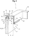
- the decorative element 51 may, as in the embodiment shown the Fig. 2 represented formed by a cross-section L or J-shaped plastic strip which engages around the vertical wall portion 55 positively.
- the decorative element 51 on the holding device 49, in particular on the vertical wall portion 55 is snapped, clamped, glued, integrally formed in two-component injection molding and / or laminated.
- the Fig. 5 shows an alternative embodiment in which the holding device 49 is not formed integrally with the fastening device 39 and / or the edge trim strip 33, but in which the holding device 49 is formed as a separate component 59 and connected to the fastening device 39 and the edge trim strip 33.
- the separate component 59, the vertical wall portion 55, the horizontal wall portion 53 and a clamping portion 61 which is formed, the separate component 59 on the fastening device 39 and the edge trim strip 33rd to fix.
- the clamping portion 61 has a C-shaped cross section, wherein an upper projection 63 and a lower projection 65 engage around the second leg portion 37 of the fastening device 39.
- the upper projection 63 and the lower projection 65 are adapted to the second leg portion 37 of the fastening device 39 in shape and / or size such that the C-shaped clamping portion 61 is preferably frictionally held on the second leg portion 37 of the fastening device 39 and the edge trim strip 33 is.
- the fastening device 39 can, as shown, mounted flush on the upper edge 25 of the main body 11 and secured by seals or adhesive strips 67.
- Fig. 6 is a variation of the alternative embodiment according to Fig. 5 shown in non-perspective view in cross section.
- the embodiment according to Fig. 6 differs from the embodiment according to Fig. 5 by an altered upper projection 63, which has a fastening device 39 and the edge trim strip 33 contacting surface which is not horizontally aligned with the fastening device 39 and the edge trim strip 33, but rather is aligned at a 45-degree angle and in this 45-degree angle to the fastening device 39 and abuts the edge trim strip 33.
- the upper projection 63 is formed as an optically hidden projection.
- second leg portion 37 of the fastening device 39 has a horizontally extending groove 69.
- the upper projection 63 is designed as a rib corresponding to the groove 69, which engages in the groove 69.
- the lower projection 65 may be formed as a latching edge which, due to a certain elasticity of the clamping portion 61, may latch around the second leg portion 37 at a lower end.
Landscapes
- Engineering & Computer Science (AREA)
- Chemical & Material Sciences (AREA)
- Combustion & Propulsion (AREA)
- Physics & Mathematics (AREA)
- Mechanical Engineering (AREA)
- Thermal Sciences (AREA)
- General Engineering & Computer Science (AREA)
- Refrigerator Housings (AREA)
- Connection Of Plates (AREA)
Claims (11)
- Appareil frigorifique ménager, présentant un espace de stockage (4, 5) pour les denrées à réfrigérer et au moins un contenant de dépose (7) disposé dans l'espace de stockage (4, 5), lequel contenant de dépose présente un corps de base (11) avec au moins une section de paroi transparente (23) et un rebord (33) fixé au corps de base (11), caractérisé en ce que le rebord (33) présente un dispositif de retenue (49) auquel un élément décoratif (51) est fixé et le dispositif de retenue (49) et/ou l'élément décoratif (51) est exécuté de sorte à positionner l'élément décoratif (51) de façon visible derrière un côté arrière (47) de la section de paroi transparente (23), de l'extérieur du corps de base (11) à travers la section de paroi transparente (23).
- Appareil frigorifique ménager selon la revendication 1, caractérisé en ce que le dispositif de retenue (49) et/ou l'élément décoratif (51) est exécuté de sorte à positionner l'élément décoratif (51) selon un écartement (A) par rapport au côté arrière (47) de la section de paroi transparente (23), en particulier selon un écartement (A) d'au moins un millimètre, de préférence selon un écartement (A) situé entre un et dix millimètres du côté arrière (47) de la section de paroi transparente (23).
- Appareil frigorifique ménager selon la revendication 1 ou 2, caractérisé en ce que le rebord (33) présente un dispositif de fixation (39) exécuté afin de fixer le rebord (33) au corps de base (11) et le dispositif de retenue (49) présente une section de paroi horizontale (53) reliée au dispositif de fixation (39) et une section de paroi verticale (55) présentant l'élément décoratif (51).
- Appareil frigorifique ménager selon l'une des revendications 1 à 3, caractérisé en ce que l'élément décoratif (51) est encliqueté, pressé contre, collé, formé selon un procédé de moulage par injection à deux composants et/ou appliqué par contre-collage sur le dispositif de retenue (49), en particulier sur la section de paroi verticale (55).
- Appareil frigorifique ménager selon la revendication 3 ou 4, caractérisé en ce que le dispositif de retenue (49) est exécuté en une seule pièce avec le dispositif de fixation (39) et/ou le rebord (33).
- Appareil frigorifique ménager selon la revendication 3 ou 4, caractérisé en ce que le dispositif de retenue (49) est exécuté sous la forme d'un composant distinct (59) et relié au dispositif de fixation (39) et/ou au rebord (33).
- Appareil frigorifique ménager selon l'une des revendications 1 à 6, caractérisé en ce que le dispositif de retenue (49) ou la section de paroi verticale (55) du dispositif de retenue (49) s'étend, dans une position du rebord (33) fixé au corps de base (11) au moins dans une zone (B) de la section de paroi transparente (23) du corps de base (11) à travers une extrémité inférieure (57) du dispositif de fixation (39), en traversant cette zone vers le bas.
- Appareil frigorifique ménager selon l'une des revendications 1 à 6, caractérisé en ce que le dispositif de fixation (39) présente une section de cadre (31) entourant le bord supérieur (25) du corps de base (11) au moins dans la zone de la section de paroi transparente (23) et deux dispositifs d'encliquetage (41) s'engrenant sur des parois latérales opposées (21a, 21b) du corps de base (11), reliés à la section de cadre (31).
- Appareil frigorifique ménager selon la revendication 8, caractérisé en ce que la section de cadre (31) et les dispositifs d'encliquetage (41) sont exécutés afin de presser, dans une position du rebord (33) fixé au corps de base (11), la section de cadre (31) en générant une force de précontrainte contre le corps de base (11), lorsque les dispositifs d'encliquetage (41) sont encliquetés sur les parois latérales (21 a, 21 b) du corps de base (11).
- Appareil frigorifique ménager selon la revendication 9, caractérisé en ce que la section de cadre (31) est, dans la position encliquetée et précontrainte du rebord (33) contiguë sans encliquetage et/ou sans adhésif au corps de base (11), en particulier à un bord supérieur (25) du corps de base (11), en particulier sans intervalle.
- Appareil frigorifique ménager selon la revendication 10, caractérisé en ce que le bord supérieur (25) du corps de base (11) est doté d'un chanfrein (27), en particulier d'un chanfrein à 45 degrés (27) par rapport à la section de paroi transparente (23) du corps de base (11), sur laquelle la section de cadre (31) du dispositif de fixation (39) resp. du rebord (33) repose en particulier en formant une surface plane.
Priority Applications (1)
| Application Number | Priority Date | Filing Date | Title |
|---|---|---|---|
| PL13723525T PL2856048T3 (pl) | 2012-05-29 | 2013-05-22 | Urządzenie chłodnicze gospodarstwa domowego z pojemnikiem do przechowywania i z brzegową listwą wykończeniową |
Applications Claiming Priority (2)
| Application Number | Priority Date | Filing Date | Title |
|---|---|---|---|
| DE102012208985A DE102012208985A1 (de) | 2012-05-29 | 2012-05-29 | Haushaltskältegerät mit einem Abstellbehälter und einer Randabschlussleiste |
| PCT/EP2013/060504 WO2013178516A1 (fr) | 2012-05-29 | 2013-05-22 | Appareil frigorifique ménager comprenant un balconnet et une baguette terminale de bord |
Publications (2)
| Publication Number | Publication Date |
|---|---|
| EP2856048A1 EP2856048A1 (fr) | 2015-04-08 |
| EP2856048B1 true EP2856048B1 (fr) | 2018-09-19 |
Family
ID=48464020
Family Applications (1)
| Application Number | Title | Priority Date | Filing Date |
|---|---|---|---|
| EP13723525.5A Active EP2856048B1 (fr) | 2012-05-29 | 2013-05-22 | Appareil frigorifique ménager comprenant un balconnet et une baguette terminale de bord |
Country Status (4)
| Country | Link |
|---|---|
| EP (1) | EP2856048B1 (fr) |
| DE (1) | DE102012208985A1 (fr) |
| PL (1) | PL2856048T3 (fr) |
| WO (1) | WO2013178516A1 (fr) |
Families Citing this family (3)
| Publication number | Priority date | Publication date | Assignee | Title |
|---|---|---|---|---|
| DE102016002296A1 (de) * | 2015-12-30 | 2017-07-06 | Liebherr-Hausgeräte Ochsenhausen GmbH | Schublade für ein Kühl- und/oder Gefriergerät |
| DE102018203431A1 (de) * | 2018-03-07 | 2019-09-12 | BSH Hausgeräte GmbH | Kühlgutabstellfach mit L-förmigen Rahmen, Tür sowie Haushaltskältegerät |
| DE102020210128A1 (de) | 2020-08-11 | 2022-02-17 | BSH Hausgeräte GmbH | Lebensmittel-Aufnahmebehälter mit spezifischer optischer Vorrichtung zur Wandstärkendarstellung einer Seitenwand, sowie Haushaltskältegerät |
Family Cites Families (6)
| Publication number | Priority date | Publication date | Assignee | Title |
|---|---|---|---|---|
| US5437503A (en) * | 1993-06-01 | 1995-08-01 | General Electric Company | Modular storage drawer assembly for use in a refrigerator |
| JPH08210767A (ja) * | 1995-02-06 | 1996-08-20 | Matsushita Refrig Co Ltd | 冷蔵庫扉 |
| DE202005012342U1 (de) * | 2005-08-05 | 2005-10-20 | BSH Bosch und Siemens Hausgeräte GmbH | Modular Kühlgutbehälter |
| US7770985B2 (en) * | 2006-02-15 | 2010-08-10 | Maytag Corporation | Kitchen appliance having floating glass panel |
| DE102008019261A1 (de) | 2008-04-11 | 2009-10-15 | BSH Bosch und Siemens Hausgeräte GmbH | Haushalts-Kältegerät mit mindestens einem Abstellbehältnis |
| DE102009028435A1 (de) * | 2009-08-10 | 2011-02-17 | BSH Bosch und Siemens Hausgeräte GmbH | Abstellfach für ein Kältegerät |
-
2012
- 2012-05-29 DE DE102012208985A patent/DE102012208985A1/de not_active Withdrawn
-
2013
- 2013-05-22 WO PCT/EP2013/060504 patent/WO2013178516A1/fr active Application Filing
- 2013-05-22 PL PL13723525T patent/PL2856048T3/pl unknown
- 2013-05-22 EP EP13723525.5A patent/EP2856048B1/fr active Active
Non-Patent Citations (1)
| Title |
|---|
| None * |
Also Published As
| Publication number | Publication date |
|---|---|
| DE102012208985A1 (de) | 2013-12-05 |
| PL2856048T3 (pl) | 2019-04-30 |
| EP2856048A1 (fr) | 2015-04-08 |
| WO2013178516A1 (fr) | 2013-12-05 |
Similar Documents
| Publication | Publication Date | Title |
|---|---|---|
| EP2638344B1 (fr) | Pièce de support pour la fixation d'un élément électrique sur une paroi de boîtier | |
| EP3161397B1 (fr) | Réfrigérateur domestique avec un éclairage intérieur | |
| EP2156123B1 (fr) | Support de marchandise réfrigérée | |
| EP2409097B1 (fr) | Appareil réfrigérant ménager et balconnet de rangement pour un appareil réfrigérant | |
| EP2235451B1 (fr) | Conteneur de stockage pour appareil frigorifique | |
| EP1825200A1 (fr) | Systeme de refrigeration et/ou de congelation | |
| EP1882140A1 (fr) | Contenant interne d'un appareil refrigerant | |
| EP2856048B1 (fr) | Appareil frigorifique ménager comprenant un balconnet et une baguette terminale de bord | |
| DE10322974A1 (de) | Tür für ein Kältegerät | |
| EP2276987B1 (fr) | Appareil frigorifique | |
| EP1379820A1 (fr) | Recipient de stockage pour appareils frigorifiques | |
| DE102008019261A1 (de) | Haushalts-Kältegerät mit mindestens einem Abstellbehältnis | |
| DE202008005350U1 (de) | Abstellbehälter für ein Kältegerät | |
| EP2641040B1 (fr) | Porte d'appareil de froid | |
| DE102009002802A1 (de) | Kältegerät mit einer Kühlgutablage | |
| DE102010044076A1 (de) | Kältegerätetür | |
| EP2457042B1 (fr) | Appareil frigorifique domestique comprenant une clayette, clayette et procédé de fabrication d'une clayette | |
| EP3537077B1 (fr) | Compartiment de stockage pour produits à réfrigérer pourvu d'un cadre en l, porte ainsi qu'appareil de refroidissement électroménager | |
| EP3628945B1 (fr) | Porte pour un appareil électroménager pourvue de panneau décoratif avant et élément de protection pour le bord du panneau décoratif et appareil électroménager | |
| EP2244043B1 (fr) | Appareil frigorifique et récipient intérieur correspondant | |
| DE3121798A1 (de) | Sockelblende fuer moebel, insbesondere kuechenmoebel | |
| DE102011007845A1 (de) | Blende für ein Haushaltsgerät sowie Haushaltsgerät | |
| DE102008041559B4 (de) | Kältegerät | |
| DE102012209877A1 (de) | Einbauteil für ein Kältegerät | |
| EP2667127A2 (fr) | Appareil frigorifique, en particulier appareil ménager |
Legal Events
| Date | Code | Title | Description |
|---|---|---|---|
| PUAI | Public reference made under article 153(3) epc to a published international application that has entered the european phase |
Free format text: ORIGINAL CODE: 0009012 |
|
| 17P | Request for examination filed |
Effective date: 20150105 |
|
| AK | Designated contracting states |
Kind code of ref document: A1 Designated state(s): AL AT BE BG CH CY CZ DE DK EE ES FI FR GB GR HR HU IE IS IT LI LT LU LV MC MK MT NL NO PL PT RO RS SE SI SK SM TR |
|
| AX | Request for extension of the european patent |
Extension state: BA ME |
|
| RIN1 | Information on inventor provided before grant (corrected) |
Inventor name: BORMANN, MARIETTA Inventor name: EICHER, MAX Inventor name: FINK, JUERGEN Inventor name: KIRSCHBAUM, MAIKE Inventor name: BECKE, CHRISTOPH Inventor name: CIZIK, HERBERT Inventor name: TISCHER, THOMAS Inventor name: GORODEZKI, SWETLANA Inventor name: BOBE, MIRKO Inventor name: STAUD, RALPH |
|
| DAX | Request for extension of the european patent (deleted) | ||
| GRAP | Despatch of communication of intention to grant a patent |
Free format text: ORIGINAL CODE: EPIDOSNIGR1 |
|
| STAA | Information on the status of an ep patent application or granted ep patent |
Free format text: STATUS: GRANT OF PATENT IS INTENDED |
|
| INTG | Intention to grant announced |
Effective date: 20180509 |
|
| GRAS | Grant fee paid |
Free format text: ORIGINAL CODE: EPIDOSNIGR3 |
|
| GRAA | (expected) grant |
Free format text: ORIGINAL CODE: 0009210 |
|
| STAA | Information on the status of an ep patent application or granted ep patent |
Free format text: STATUS: THE PATENT HAS BEEN GRANTED |
|
| AK | Designated contracting states |
Kind code of ref document: B1 Designated state(s): AL AT BE BG CH CY CZ DE DK EE ES FI FR GB GR HR HU IE IS IT LI LT LU LV MC MK MT NL NO PL PT RO RS SE SI SK SM TR |
|
| REG | Reference to a national code |
Ref country code: GB Ref legal event code: FG4D Free format text: NOT ENGLISH |
|
| REG | Reference to a national code |
Ref country code: CH Ref legal event code: EP |
|
| REG | Reference to a national code |
Ref country code: DE Ref legal event code: R096 Ref document number: 502013011118 Country of ref document: DE |
|
| REG | Reference to a national code |
Ref country code: AT Ref legal event code: REF Ref document number: 1043724 Country of ref document: AT Kind code of ref document: T Effective date: 20181015 |
|
| REG | Reference to a national code |
Ref country code: IE Ref legal event code: FG4D Free format text: LANGUAGE OF EP DOCUMENT: GERMAN |
|
| REG | Reference to a national code |
Ref country code: NL Ref legal event code: MP Effective date: 20180919 |
|
| PG25 | Lapsed in a contracting state [announced via postgrant information from national office to epo] |
Ref country code: SE Free format text: LAPSE BECAUSE OF FAILURE TO SUBMIT A TRANSLATION OF THE DESCRIPTION OR TO PAY THE FEE WITHIN THE PRESCRIBED TIME-LIMIT Effective date: 20180919 Ref country code: LT Free format text: LAPSE BECAUSE OF FAILURE TO SUBMIT A TRANSLATION OF THE DESCRIPTION OR TO PAY THE FEE WITHIN THE PRESCRIBED TIME-LIMIT Effective date: 20180919 Ref country code: RS Free format text: LAPSE BECAUSE OF FAILURE TO SUBMIT A TRANSLATION OF THE DESCRIPTION OR TO PAY THE FEE WITHIN THE PRESCRIBED TIME-LIMIT Effective date: 20180919 Ref country code: GR Free format text: LAPSE BECAUSE OF FAILURE TO SUBMIT A TRANSLATION OF THE DESCRIPTION OR TO PAY THE FEE WITHIN THE PRESCRIBED TIME-LIMIT Effective date: 20181220 Ref country code: FI Free format text: LAPSE BECAUSE OF FAILURE TO SUBMIT A TRANSLATION OF THE DESCRIPTION OR TO PAY THE FEE WITHIN THE PRESCRIBED TIME-LIMIT Effective date: 20180919 Ref country code: BG Free format text: LAPSE BECAUSE OF FAILURE TO SUBMIT A TRANSLATION OF THE DESCRIPTION OR TO PAY THE FEE WITHIN THE PRESCRIBED TIME-LIMIT Effective date: 20181219 Ref country code: NO Free format text: LAPSE BECAUSE OF FAILURE TO SUBMIT A TRANSLATION OF THE DESCRIPTION OR TO PAY THE FEE WITHIN THE PRESCRIBED TIME-LIMIT Effective date: 20181219 |
|
| REG | Reference to a national code |
Ref country code: LT Ref legal event code: MG4D |
|
| PG25 | Lapsed in a contracting state [announced via postgrant information from national office to epo] |
Ref country code: AL Free format text: LAPSE BECAUSE OF FAILURE TO SUBMIT A TRANSLATION OF THE DESCRIPTION OR TO PAY THE FEE WITHIN THE PRESCRIBED TIME-LIMIT Effective date: 20180919 Ref country code: HR Free format text: LAPSE BECAUSE OF FAILURE TO SUBMIT A TRANSLATION OF THE DESCRIPTION OR TO PAY THE FEE WITHIN THE PRESCRIBED TIME-LIMIT Effective date: 20180919 Ref country code: LV Free format text: LAPSE BECAUSE OF FAILURE TO SUBMIT A TRANSLATION OF THE DESCRIPTION OR TO PAY THE FEE WITHIN THE PRESCRIBED TIME-LIMIT Effective date: 20180919 |
|
| PG25 | Lapsed in a contracting state [announced via postgrant information from national office to epo] |
Ref country code: EE Free format text: LAPSE BECAUSE OF FAILURE TO SUBMIT A TRANSLATION OF THE DESCRIPTION OR TO PAY THE FEE WITHIN THE PRESCRIBED TIME-LIMIT Effective date: 20180919 Ref country code: NL Free format text: LAPSE BECAUSE OF FAILURE TO SUBMIT A TRANSLATION OF THE DESCRIPTION OR TO PAY THE FEE WITHIN THE PRESCRIBED TIME-LIMIT Effective date: 20180919 Ref country code: RO Free format text: LAPSE BECAUSE OF FAILURE TO SUBMIT A TRANSLATION OF THE DESCRIPTION OR TO PAY THE FEE WITHIN THE PRESCRIBED TIME-LIMIT Effective date: 20180919 Ref country code: CZ Free format text: LAPSE BECAUSE OF FAILURE TO SUBMIT A TRANSLATION OF THE DESCRIPTION OR TO PAY THE FEE WITHIN THE PRESCRIBED TIME-LIMIT Effective date: 20180919 Ref country code: ES Free format text: LAPSE BECAUSE OF FAILURE TO SUBMIT A TRANSLATION OF THE DESCRIPTION OR TO PAY THE FEE WITHIN THE PRESCRIBED TIME-LIMIT Effective date: 20180919 Ref country code: IS Free format text: LAPSE BECAUSE OF FAILURE TO SUBMIT A TRANSLATION OF THE DESCRIPTION OR TO PAY THE FEE WITHIN THE PRESCRIBED TIME-LIMIT Effective date: 20190119 |
|
| PG25 | Lapsed in a contracting state [announced via postgrant information from national office to epo] |
Ref country code: SK Free format text: LAPSE BECAUSE OF FAILURE TO SUBMIT A TRANSLATION OF THE DESCRIPTION OR TO PAY THE FEE WITHIN THE PRESCRIBED TIME-LIMIT Effective date: 20180919 Ref country code: PT Free format text: LAPSE BECAUSE OF FAILURE TO SUBMIT A TRANSLATION OF THE DESCRIPTION OR TO PAY THE FEE WITHIN THE PRESCRIBED TIME-LIMIT Effective date: 20190119 Ref country code: SM Free format text: LAPSE BECAUSE OF FAILURE TO SUBMIT A TRANSLATION OF THE DESCRIPTION OR TO PAY THE FEE WITHIN THE PRESCRIBED TIME-LIMIT Effective date: 20180919 |
|
| REG | Reference to a national code |
Ref country code: DE Ref legal event code: R097 Ref document number: 502013011118 Country of ref document: DE |
|
| PLBE | No opposition filed within time limit |
Free format text: ORIGINAL CODE: 0009261 |
|
| STAA | Information on the status of an ep patent application or granted ep patent |
Free format text: STATUS: NO OPPOSITION FILED WITHIN TIME LIMIT |
|
| PG25 | Lapsed in a contracting state [announced via postgrant information from national office to epo] |
Ref country code: DK Free format text: LAPSE BECAUSE OF FAILURE TO SUBMIT A TRANSLATION OF THE DESCRIPTION OR TO PAY THE FEE WITHIN THE PRESCRIBED TIME-LIMIT Effective date: 20180919 |
|
| 26N | No opposition filed |
Effective date: 20190620 |
|
| PG25 | Lapsed in a contracting state [announced via postgrant information from national office to epo] |
Ref country code: SI Free format text: LAPSE BECAUSE OF FAILURE TO SUBMIT A TRANSLATION OF THE DESCRIPTION OR TO PAY THE FEE WITHIN THE PRESCRIBED TIME-LIMIT Effective date: 20180919 |
|
| REG | Reference to a national code |
Ref country code: CH Ref legal event code: PL |
|
| GBPC | Gb: european patent ceased through non-payment of renewal fee |
Effective date: 20190522 |
|
| PG25 | Lapsed in a contracting state [announced via postgrant information from national office to epo] |
Ref country code: CH Free format text: LAPSE BECAUSE OF NON-PAYMENT OF DUE FEES Effective date: 20190531 Ref country code: LI Free format text: LAPSE BECAUSE OF NON-PAYMENT OF DUE FEES Effective date: 20190531 Ref country code: MC Free format text: LAPSE BECAUSE OF FAILURE TO SUBMIT A TRANSLATION OF THE DESCRIPTION OR TO PAY THE FEE WITHIN THE PRESCRIBED TIME-LIMIT Effective date: 20180919 |
|
| REG | Reference to a national code |
Ref country code: BE Ref legal event code: MM Effective date: 20190531 |
|
| PG25 | Lapsed in a contracting state [announced via postgrant information from national office to epo] |
Ref country code: LU Free format text: LAPSE BECAUSE OF NON-PAYMENT OF DUE FEES Effective date: 20190522 |
|
| PG25 | Lapsed in a contracting state [announced via postgrant information from national office to epo] |
Ref country code: GB Free format text: LAPSE BECAUSE OF NON-PAYMENT OF DUE FEES Effective date: 20190522 Ref country code: IE Free format text: LAPSE BECAUSE OF NON-PAYMENT OF DUE FEES Effective date: 20190522 |
|
| PG25 | Lapsed in a contracting state [announced via postgrant information from national office to epo] |
Ref country code: BE Free format text: LAPSE BECAUSE OF NON-PAYMENT OF DUE FEES Effective date: 20190531 |
|
| PG25 | Lapsed in a contracting state [announced via postgrant information from national office to epo] |
Ref country code: FR Free format text: LAPSE BECAUSE OF NON-PAYMENT OF DUE FEES Effective date: 20190531 |
|
| REG | Reference to a national code |
Ref country code: AT Ref legal event code: MM01 Ref document number: 1043724 Country of ref document: AT Kind code of ref document: T Effective date: 20190522 |
|
| PG25 | Lapsed in a contracting state [announced via postgrant information from national office to epo] |
Ref country code: AT Free format text: LAPSE BECAUSE OF NON-PAYMENT OF DUE FEES Effective date: 20190522 |
|
| PG25 | Lapsed in a contracting state [announced via postgrant information from national office to epo] |
Ref country code: CY Free format text: LAPSE BECAUSE OF FAILURE TO SUBMIT A TRANSLATION OF THE DESCRIPTION OR TO PAY THE FEE WITHIN THE PRESCRIBED TIME-LIMIT Effective date: 20180919 |
|
| PG25 | Lapsed in a contracting state [announced via postgrant information from national office to epo] |
Ref country code: HU Free format text: LAPSE BECAUSE OF FAILURE TO SUBMIT A TRANSLATION OF THE DESCRIPTION OR TO PAY THE FEE WITHIN THE PRESCRIBED TIME-LIMIT; INVALID AB INITIO Effective date: 20130522 Ref country code: MT Free format text: LAPSE BECAUSE OF FAILURE TO SUBMIT A TRANSLATION OF THE DESCRIPTION OR TO PAY THE FEE WITHIN THE PRESCRIBED TIME-LIMIT Effective date: 20180919 |
|
| PG25 | Lapsed in a contracting state [announced via postgrant information from national office to epo] |
Ref country code: MK Free format text: LAPSE BECAUSE OF FAILURE TO SUBMIT A TRANSLATION OF THE DESCRIPTION OR TO PAY THE FEE WITHIN THE PRESCRIBED TIME-LIMIT Effective date: 20180919 |
|
| PGFP | Annual fee paid to national office [announced via postgrant information from national office to epo] |
Ref country code: IT Payment date: 20220531 Year of fee payment: 10 |
|
| PG25 | Lapsed in a contracting state [announced via postgrant information from national office to epo] |
Ref country code: IT Free format text: LAPSE BECAUSE OF NON-PAYMENT OF DUE FEES Effective date: 20230522 |
|
| PGFP | Annual fee paid to national office [announced via postgrant information from national office to epo] |
Ref country code: DE Payment date: 20240531 Year of fee payment: 12 |
|
| PGFP | Annual fee paid to national office [announced via postgrant information from national office to epo] |
Ref country code: PL Payment date: 20240515 Year of fee payment: 12 |
|
| PGFP | Annual fee paid to national office [announced via postgrant information from national office to epo] |
Ref country code: TR Payment date: 20240513 Year of fee payment: 12 |